

ChargePoint CT21002000-01 Users Manual
CT2100 Family
by Coulomb Technologies
®
®
ChargePoint
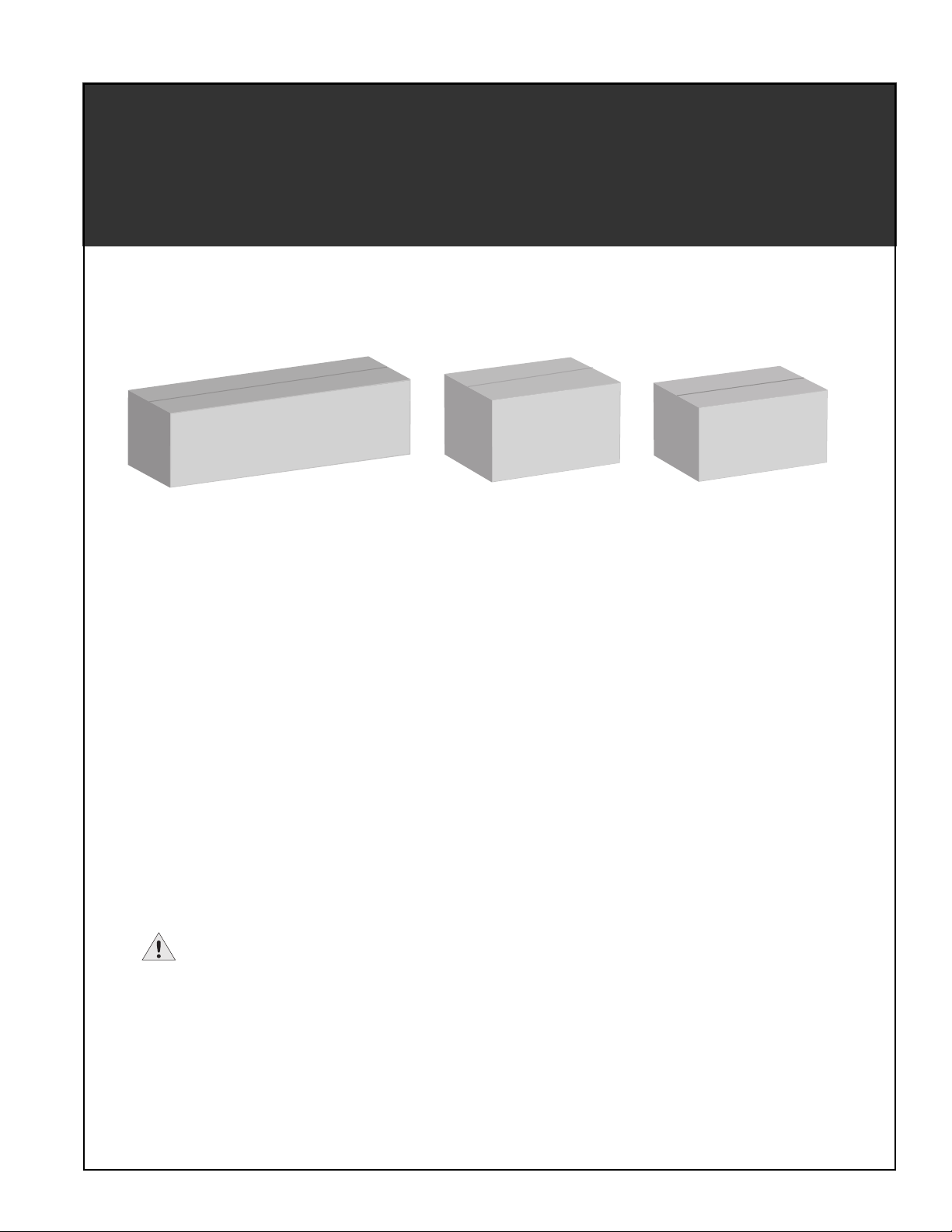
CT2101 Bollard Mount CT2102 Pole Mount CT2103 Wall Mount
Networked Charging Stations
Coulomb Technologies Inc.
1692 Dell Ave.
Campbell, CA 95008-6901 USA
US toll free: +1-877-370-3802
www.coulombtech.com
www.mychargepoint.net
Installation
Guide
Part Number: 75-001020 Revision: 1.1

IMPORTANT SAFETY INSTRUCTIONS
SAVE THESE INSTRUCTIONS
This manual contains important instructions that must be followed during installation of a ChargePoint® Networked Charging Station.
Grounding instructions
The ChargePoint® Charging Station must be connected to a grounded, metal, permanent wiring system; or an equipment-grounding conductor is
to be run with circuit conductors and connected to the equipment grounding terminal or lead on the Electric Vehicle Supply Equipment (EVSE).
Connections to the EVSE shall comply with all local codes and ordinances.
FCC Compliance Statement
This equipment has been tested and found to comply with the limits for a Class A digital device pursuant to Part 15 of the FCC Rules. These limits
are designed to provide reasonable protection against harmful interference when the equipment is operated in a commercial environment. This
equipment generates, uses, and can radiate radio frequency energy and, if not installed and used in accordance with the manufacturer’s
instruction manual, may cause harmful interference with radio communications. Operation of this equipment in a residential area is likely to
cause harmful interference, in which case, you will be required to correct the interference at your own expense.
Important: Changes or modifications to this product not authorized by Coulomb Technologies, Inc., could affect the EMC compliance and revoke
your authority to operate this product.
Exposure to Radio Frequency Energy: The radiated power output of the Zigbee radio and cellular modem (optional) in this device is below the FCC
radio frequency exposure limits for uncontrolled equipment. This device should be operated with a minimum distance of at least 20 cm between
the Zigbee and Cellular antennas and a person’s body and must not be co-located or operated with any other antenna or transmitter by the
manufacturer, subject to the conditions of the FCC Grant.
Safety and compliance
This document provides instructions to install the ChargePoint® Charging Station and should not be used for any other product. Before installing
the ChargePoint
trained installation expert to ensure compliance with local building practices, climate conditions, safety standards, and state and local codes.
The ChargePoint
and national codes and standards. The ChargePoint
no circumstances will compliance with the information in this manual relieve the user of his/her responsibility to comply with all applicable codes
or safety standards. This document describes the most commonly-used installation and mounting scenarios. If situations arise in which it is not
possible to perform an installation following the procedures provided in this document, contact Coulomb Technologies. Coulomb Technologies is
not responsible for any damages that may occur resulting from custom installations that are not described in this document.
®
Charging Station, you should review this manual carefully and consult with a licensed contractor, licensed electrician and
®
Charging Station should be installed only by a licensed contractor and a licensed electrician and in accordance with all local
®
Charging Station should be inspected by a qualified installer prior to the initial use. Under
No accuracy guarantee
Reasonable effort was made to ensure that the specifications and other information in this manual are accurate and complete at the time of its
publication. However, the specifications and other information in this manual are subject to change at any time without prior notice.
Warranty information and disclaimer
Your use of, or modification to, the ChargePoint® Charging Station in a manner in which the ChargePoint® Charging Station is not intended to be
used or modified will void the limited warranty. Other than any such limited warranty, the Coulomb products are provided “AS IS,” and Coulomb
and its distributors expressly disclaim all implied warranties, including any warranty of design, merchantability, fitness for a particular purposes
and non-infringement, to the maximum extent permitted by law.
Limitation of liability
IN NO EVENT SHALL COULOMB TECHNOLOGIES, INC. OR ITS AUTHORIZED DISTRIBUTORS BE LIABLE FOR ANY INDIRECT,
INCIDENTAL, SPECIAL, PUNITIVE, OR CONSEQUENTIAL DAMAGES, INCLUDING WITHOUT LIMITATION, LOST PROFITS, LOST
®
DATA, LOSS OF USE, COST OF COVER, OR LOSS OR DAMAGE TO THE CHARGEPOINT
CHARGING STATION, ARISING OUT OF
OR RELATING TO THE USE OR INABILITY TO USE THIS MANUAL, EVEN IF COULOMB TECHNOLOGIES, INC. OR ITS
AUTHORIZED DISTRIBUTORS HAVE BEEN ADVISED OF THE POSSIBILITY OF SUCH DAMAGES.
Copyright and Trademarks
©2010 Coulomb Technologies, Inc. All rights reserved. This material is protected by the copyright laws of the United States and other countries. It
may not be modified, reproduced or distributed without the prior, express written consent of Coulomb Technologies, Inc. CHARGEPOINT is a U.S.
registered trademark and service mark of Coulomb Technologies, Inc. All other products or services mentioned are the trademarks, service
marks, registered trademarks or registered service marks of their respective owners. Coulomb Technologies has filed several patent applications.

Contents
1Introduction
Before installing stations........................................................................................................................................... 1-1
Specifications.............................................................................................................................................................1-2
Wiring information ....................................................................................................................................................1-3
2 Installing a Bollard Mount
Before you start.......................................................................................................................................................... 2-1
Overview of steps.......................................................................................................................................................2-1
Step 1 - Check box for correct contents................................................................................................................... 2-2
Step 2 - Remove front panel ..................................................................................................................................... 2-3
Step 3 - Remove mounting pole and base plate from body ...................................................................................2-4
Step 4 - Install J-Bolts and conduit ........................................................................................................................... 2-5
Step 5 - Mount base plate/pole assembly............................................................................................................... 2-6
Step 6 - Install body ................................................................................................................................................... 2-7
Step 7 - Connect wires to wiring terminals...............................................................................................................2-8
Step 8 - Replace front panel ..................................................................................................................................... 2-9
3 Installing a Pole Mount
Before you start.......................................................................................................................................................... 3-1
Overview of steps.......................................................................................................................................................3-1
Step 1 - Check box for correct contents................................................................................................................... 3-2
Step 2 - Drill hole in pole ........................................................................................................................................... 3-3
Step 3 - Mount bracket to pole ................................................................................................................................. 3-4
Step 4 - Prepare body assembly for mounting.........................................................................................................3-5
Step 5 - Mount body to bracket ................................................................................................................................3-6
Step 6 - Connect wires to wiring terminals...............................................................................................................3-7
4 Installing a Wall Mount
Before you start.......................................................................................................................................................... 4-1
Overview of steps.......................................................................................................................................................4-1
Step 1 - Check box for correct contents................................................................................................................... 4-2
Step 2 - Attach bracket to wall.................................................................................................................................. 4-3
Step 3 - Remove terminal block from main body ....................................................................................................4-5
Step 4 - Drill holes in body assembly........................................................................................................................4-6
Step 5 - Attach body assembly to wall bracket........................................................................................................ 4-7
Step 6 - Attach coupler and connect conduit........................................................................................................... 4-8
Step 7 - Re-attach terminal block to main body ......................................................................................................4-9
Step 8 - Connect wires to wiring terminals.............................................................................................................4-10
5 Installing the holster and cable assembly
Before you start.......................................................................................................................................................... 5-1
Overview of steps.......................................................................................................................................................5-1
Step 1 - Check box for correct contents................................................................................................................... 5-2
Step 2 - Attach holster to body assembly................................................................................................................. 5-3
Step 2 - Install the cable assembly...........................................................................................................................5-4
6 Installing the head assembly
Before you start.......................................................................................................................................................... 6-1
Overview of steps.......................................................................................................................................................6-1
Step 1 - Check box for correct contents................................................................................................................... 6-2
Step 2 - Slide head assembly into body ...................................................................................................................6-3
Step 3 - Secure head assembly ................................................................................................................................ 6-4
i

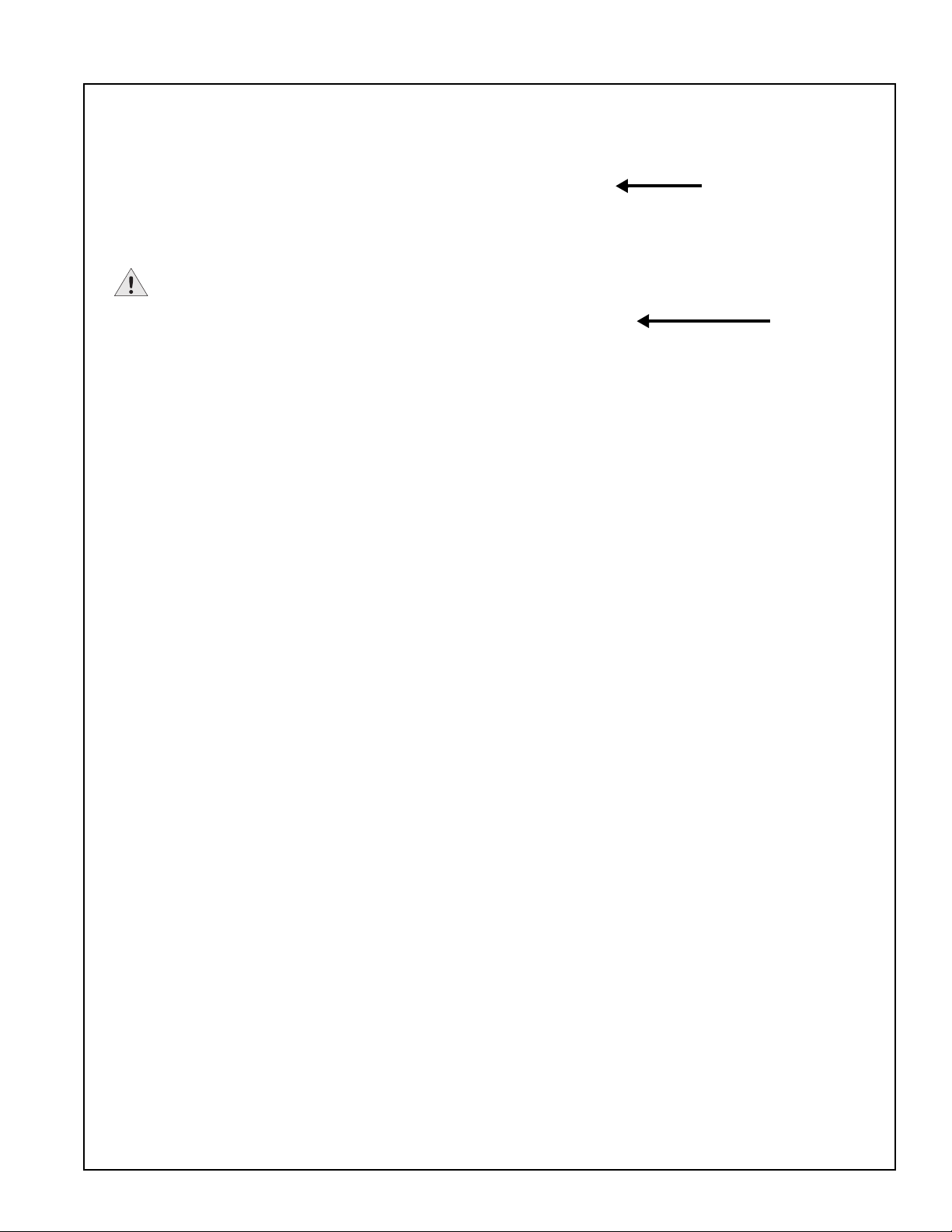
Introduction
“Body”
Install this first
CT2101 Bollard Mount - see Chapter 2
CT2102 Pole Mount - see Chapter 3
CT2103 Wall Mount - see Chapter 4
“Cable Assembly”
Install this second
See Chapter 5
“Head”
Install this last
See Chapter 6
This document provides step-by-step instructions on how to install any ChargePoint® Charging Station in
the CT2100 family. Each model ships in three boxes:
1
Before installing stations
The instructions provided in this guide assume that the appropriate wiring, circuit protection, and
metering is in place at the installation location. Before you install, you must also ensure that the type of
modem in each station you are installing is compatible with the type of modem coverage available at the
installation site (CDMA or GPRS).
To assist in the process of preparing the installation site, thoroughly review the following documents:
• wiring diagrams (provided on page 1-3 of this document)
• CT2100 Charging Stations Data Sheet (available at www.coulombtech.com by clicking the “Products”
link, then the “Library” link)
• Mounting Template for Bollard Mount and Wall Mount stations (provided in this document and in the
box containing the station’s body)
IMPORTANT: If you are printing the PDF version of the Mounting Template, be sure to print at full
scale using 11” x 17” paper.
Note: If you are installing a Bollard Mount charging station, prepare the site according to the
instructions provided in “Step 4 - Install J-Bolts and conduit” on page 2-5 of this document.
It is also recommended that before you begin installing charging stations, you thoroughly review the
contents of this document to familiarize yourself with the required installation steps.
1-1

ChargePoint® Charging Stations
Specifications
Charging connection - Level 1: NEMA 5-20R receptacle
TM
Charging connection - Level 2: SAEJ1772
AC maximum charging power output - Level 1: 1.9kW 120V @ 16A
AC maximum charging power output - Level 2: 7.2kW 240V @ 30A
AC power input: 208/240V 30A (Line 1 and Line 2) and 120V 16A (Line, Neutral, and Earth) - 5 wire
Recommended service panel breaker: 40A double pole breaker (non-GFCI type) and 20A single pole
breaker (non-GFCI type) on dedicated circuits
Integrated hardware GFCI: 20mA, CCID with self-test and auto retry (15 minute delay, 3 tries),
Level 1: 5 mA, Level 2: 20 mA
EMI compliance: FCC Part 15 Class A
Operating temperature: -22°F to 131°F (-30°C to +55°C)
Operating humidity: Up to 95% non-condensing
Terminal block temperature rating: 212°F (100°C)
EV connector on 18’ (5m) cable
Approximate shipping weight: Bollard Mount - 65 lbs (29 kg), Pole Mount - 49 lbs (22 kg), Wall
Mount - 51 lbs (23 kg).
Outdoor rated: NEMA 3R per NEMA250-1997
Safety compliance: UL Listed per UL 2231-1, 2231-2, 2594, 1998 and 991; NEC Article 625 compliant
Surge protection: 6kV @ 3000A. In geographic areas subject to frequent thunder storms, supplemental
surge protection at the service panel is recommended.
1-2
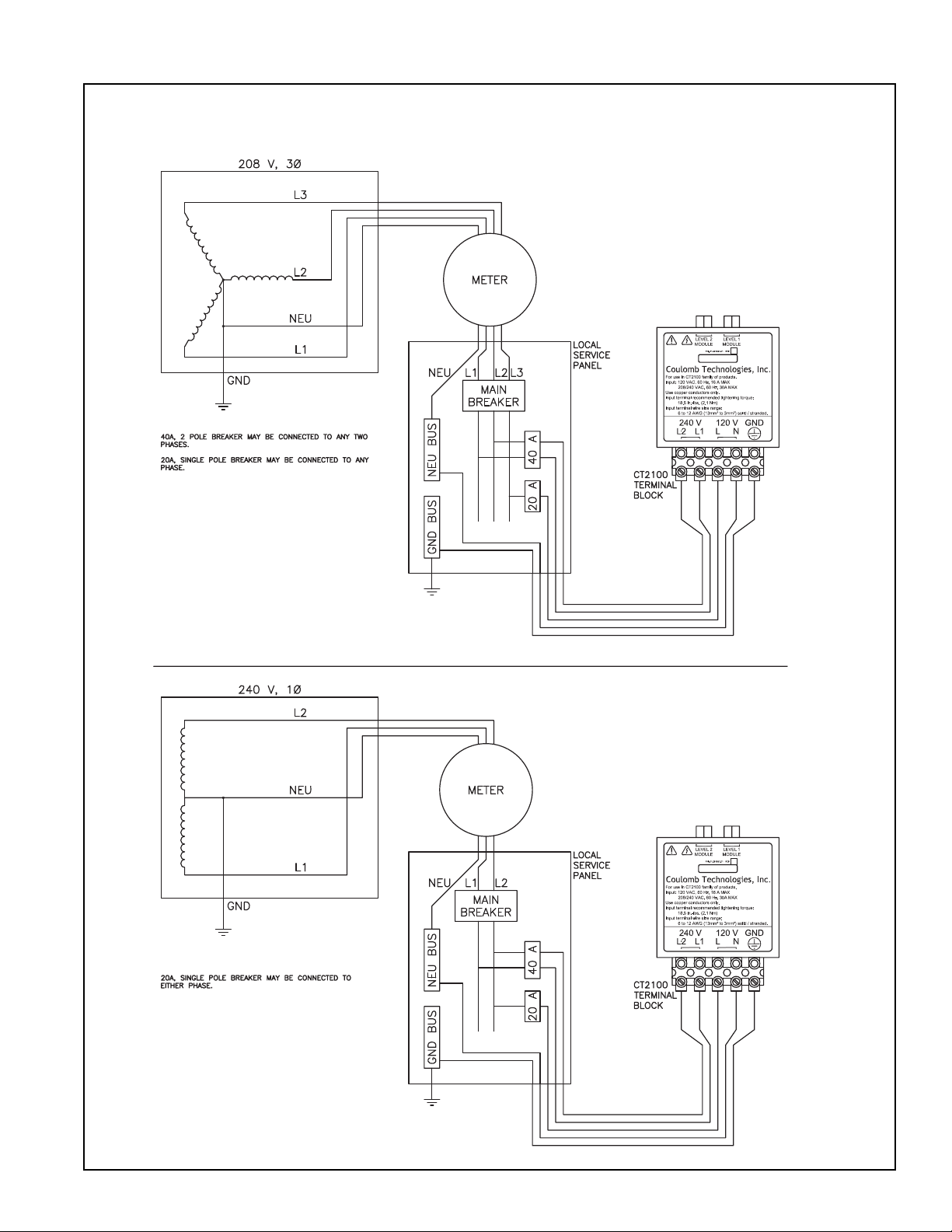
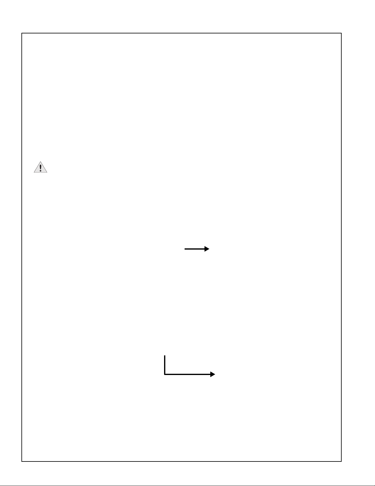
Wiring information
Introduction
1-3


Installing a Bollard Mount
Installer-supplied components:
Before you start
You will need:
®
• CT2101 ChargePoint
assembly
Charging Station body
2
• 3 J-Bolts with matching nuts and washers: up to
(12.7 mm) thread diameter, length must comply with
local codes
½” (38 mm) conduit
•1
• #2 Phillips screwdriver
• #2 Slotted screwdriver
Overview of steps
Installing the CT2101 ChargePoint® Charging Station’s
body assembly involves a few simple steps:
1. Check box for correct contents (see page 2-2)
2. Remove front panel (see page 2-3)
3. Remove mounting pole and base plate from body
(see page 2-4)
4. Install J-Bolts and conduit (see page 2-5)
5. Mount base plate/pole assembly (see page 2-6)
½”
6. Install body (see page 2-7)
7. Connect wires to wiring terminals (see page 2-8)
8. Replace front panel (see page 2-9)
These steps are detailed in the remainder of this chapter.
When you have completed these steps, you will be ready
to install the holster and cable assembly as described in
Chapter 5.
2-1
ChargePoint® Charging Stations
Front panel
Body
Mounting
pole
Base plate
The body, front panel,
mounting pole, and base
plate are pre-assembled
CT2100 Family
ChargePoint
®
Networked Charging Stations
CT2101 Bollard Moun t CT2102 Pole Mount CT2103 Wall Mount
Installation
Guide
Part Number: 75-001020 Revision: 1.1
Coulomb Technologies Inc.
1692 Dell Ave.
Campbell, CA 95008-6901 USA
US toll free: +1-877-370-3802
www.coulombtech.com
www.mychargepoint.net
by Coulomb Technologies
®
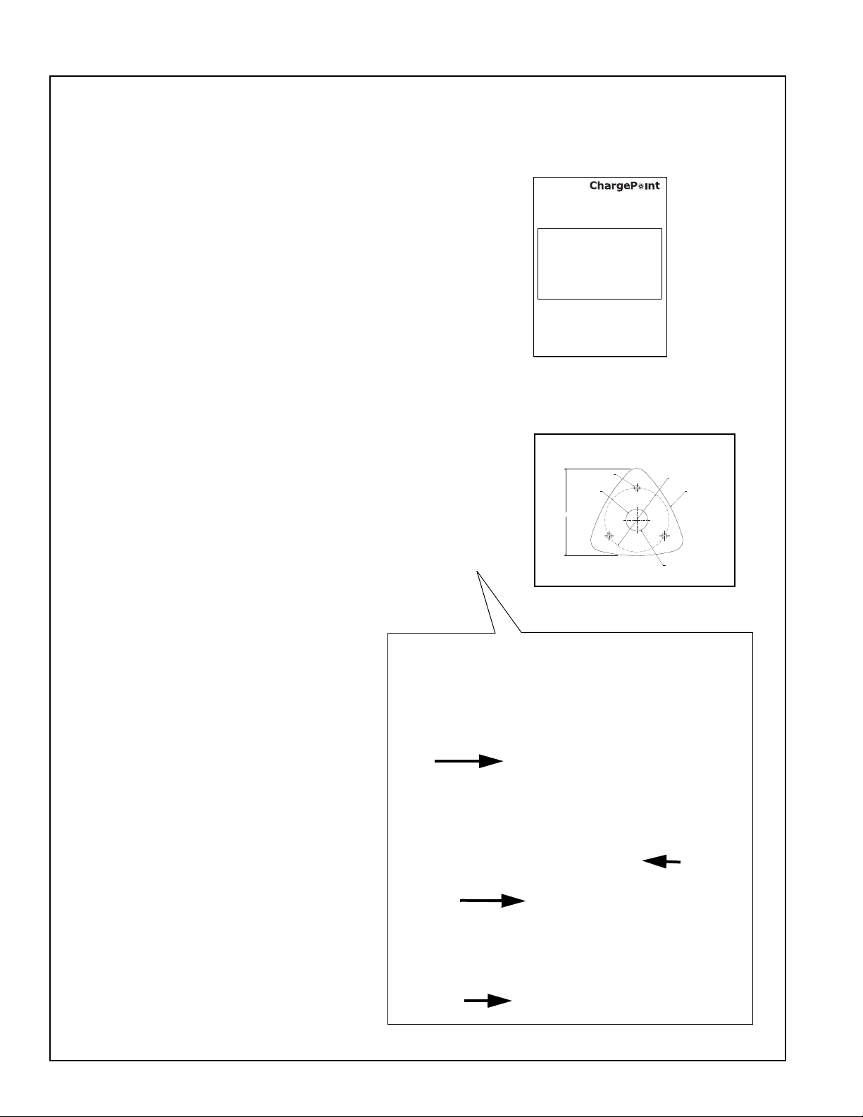
Step 1 - Check box for correct contents
Bollard Mount Assembly
The CT2101 ChargePoint® Charging
Station’s body assembly ships in a box
containing:
• Main body assembly (including body,
front panel, mounting pole, and base
plate)
• Base plate template
• Installation Guide
• 3/32” allen wrench
ANCHOR BOLT PATTERN
0.50
[12.7]
02.00
[50.8]
8.0
[203.20]
05.87
[149.2]
BOLLARD OUTSIDE ENVELOPE
FRONT
CONDUIT WITHIN THIS AREA ONLY
2-2

Step 2 - Remove front panel
To remove the front panel:
• Use the supplied allen wrench to
loosen the 2 screws that fasten the
panel to the body.
• Remove the ground wire connector
from its tab.
Slide the front panel upward to remove.
Installing a Bollard Mount
2-3

ChargePoint® Charging Stations
Loosen the four
set screws to
remove the pole.
Step 3 - Remove mounting pole and base plate from body
To remove the body:
• Use the supplied allen wrench to
loosen the 4 set screws (2 on each
bracket).
• Lift the body upward.
2-4
Step 4 - Install J-Bolts and conduit
Conduit must extend
12-24” (30-61 cm) above
the concrete (check local
codes)
J-Bolts must
extend at least
2
½” (6.4 cm)
above the
concrete
Install J-Bolts and conduit into concrete
as illustrated. Use the supplied base
plate template to ensure correct
alignment.
IMPORTANT:
• The concrete block must measure
at least 18” (46 cm) on all sides.
Check local codes to ensure
compliance.
• The J-Bolts must extend at least
2
½” (6.4 cm) above the concrete.
• The conduit must extend 12” to 24”
(30 to 61 cm) above the concrete,
or according to local codes.
Installing a Bollard Mount
2-5
ChargePoint® Charging Stations
Adjust these nuts as
necessary to ensure
the mounting pole is
level
Position a
level on the
mounting
pole
Step 5 - Mount base plate/pole assembly
Pull all five wires up through the
conduit and the mounting pole.
Place the base plate/mounting pole
assembly over the wiring conduit and
attach the base plate to the J-Bolts
using the installer-supplied nuts and
washers as shown.
Adjust the nuts as necessary to ensure
the mounting pole is level. When level,
tighten the nuts.
IMPORTANT: Ensure the base
plate/pole assembly is level by
adjusting the nuts underneath the base
plate.
2-6

Step 6 - Install body
When level, tighten
all 4 set screws
Slide the body over the mounting
pole and base plate.
Ensure the body is level.
Secure the body to the mounting
pole by tightening the four set
screws using the supplied allen
wrench.
IMPORTANT: Ensure the
body is firmly aligned to the bottom
surface and that no movement
(rocking) can take place, even
when significant pressure is
applied.
Installing a Bollard Mount
2-7
 Loading...