

Page 1
44
Manufactured by:
Charder Electronic Co., Ltd.
No.103, Guozhong Rd., Dali Dist.,
Taichung City 412, Taiwan (R.O.C.)
CD-IN-00052 [REV0002] 07/2018
1
Please keep the instruction manual at hand all the time for future reference
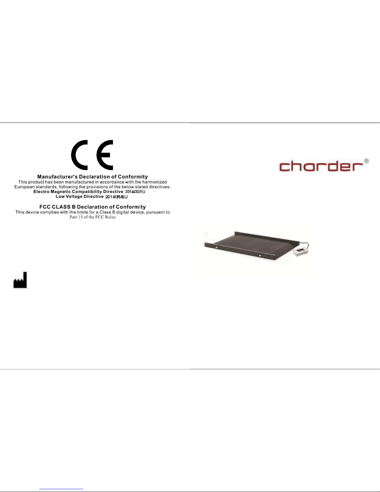
MS 3850
Medical Scale
USER MANUAL
Page 2

2
TABLE OF CONTENTS
PREFACE.....................................................................................................3
GENERAL INFORMATION.......................................................................3
SAFETY INSTRUCTION ...........................................................................3
ENVIROMENTAL....................................................................................... 4
CLEANING.................................................................................................. 4
MAINTENANCE......................................................................................... 4
WEIGHING OPERATION ..........................................................................5
WARRANTY-LIABILITY........................................................................... 5
DISPOSING OF THE SCALE..................................................................... 6
EXPLANATION OF THE GRAPHIC SYMBOLS.....................................7
EMC GUIDANCE AND MANUFACTURER'S DECLARATION ............ 8
SPECIFICATION .......................................................................................13
PANEL........................................................................................................15
LCD SYMBOL DESCRIPTION................................................................16
SYMBOLS Information............................................................................. 16
Operation.................................................................................................... 17
SETTING-UP MS3850..............................................................................22
PRINT function and data transmission.......................................................23
ASSEMBLY OF BRACKET......................................................................27
PARTS LIST OF SM-00001 SM-3461(R) & SM-3462(L)........................28
ASSEMBLY INSTRUCTION OF HANDRAILS .....................................31
ASSEMBLY OF DISPLAY........................................................................34
USING FOLDING FUNCTION................................................................ 35
INSTRUCTION FOR CHARGING AND CONNECTING......................36
INSTRUCTION FOR REPLACING BATTERIES...................................37
ERROR MESSAGE................................................................................... 38
TROUBLESHOOTING.............................................................................39
43
NOTE
Page 3
42
NOTE
3
PREFACE
Thank you for choosing CHARDER MEDICAL product. All features
of this product were designed to state of the art and are optimized for
simple and straightforward use. If you have any queries or
experience any problems not addressed in the operating instructions,
please contact your CHARDER MEDICAL service partner, or visit us
on the Internet at www.chardermedical.com
GENERAL INFORMATION
We strongly recommend you use the scales on flat and hard surface.
Any soft surface, like carpet will cause inaccuracy.
SAFETY INSTRUCTION
Before putting the device into use, please read with care the
information given in the Operating Instructions. They contain
important instructions for installation, proper use and
maintenance of the device.
The manufacturer shall not be liable for damages arising out of
failure to heed the following instructions:
These batteries should be kept away from small children. If
swallowed, promptly seek medical assistance.
Expected Service Life: 5 years
When using electrical components under increased safety
requirements, always comply with the appropriate regulations.
Improper installation will render the warranty null and void.
Ensure the voltage marked on the power supply unit matches
your main power supply.
This device is designed for use indoors.
Observe the permissible ambient temperatures for use
The device meets the requirements for electromagnetic
compatibility. Do not exceed the maximum values specified in
the applicable standards.
If you have any question, contact your local CHARDER MEDICAL
service partner.
Page 4

4
ENVIROMENTAL
All batteries contain toxic compounds; disposal of batteries should
be delegated to a competent organisation, complying with the
deposit of Poisonous Waste Regulation 1972.
Please do not incinerate batteries.
The optimum operating temperature for the scale is 5℃ to +35℃;
although it will operate at higher and lower temperatures the
scales battery life will be adversely effected.
CLEANING
We would recommend using alcohol based wipes or similar
when cleaning the scales.
Please do not use large amounts of water when cleaning the
scales as this will cause damage to the scales electronics, you
should also refrain from using corrosive liquids or high pressure
washers.
Always disconnect the scales from the mains power supply
before cleaning.
MAINTENANCE
The scale does not require any routine maintenance. However,
we recommend checking the scale’s accuracy at regular intervals.
The regularity of these checks is dependent on the level of use and
the state of the scale. If any inaccuracies occur, please contact
your local dealer or CHARDER MEDICAL service partner.
41
display screen & texts color blurred, smeared rainbow screen,
incorrect decimal display
LCD PIN broken or short circuit
PCB cooper foil broken & loosed welding
Unable to save or read data – IC or transistor faulty, internal parts
broken.
LCD showing “ERRL” after switch on - Load cell damaged
Overload may cause the weigh to malfunction.
Software system crash
Resonator faulty
Load cells with faulty grinding standard.
Key buttons failure - Front key panel damaged or disconnected
3. Buzzer malfunction
Wrong welding of PVC wire
Key buttons & control panel damaged or disconnected.
Page 5

40
2. Indicator showing “0000” ZERO SPAN out of range
Incorrect weighing result - Avoid damages by external
environment force such as free-drop to the ground, collision by
external objects, etc.
Proper re-calibration procedure required to correct the setting of
weighing accuracy.
Interference due to RF disturbance, ground vibration…etc.
Unstable platform feet adjustments according to bubble level
indication
Incorrect position or other external objects within weighing area
The weighing-scale is not put in a solid & firm ground area, such
as carpet floor or lawn.
3. Connection failure for data transmission to PC or printer
Wrong connection wires or faulty wires for transmission between
the digital indicator & load cells.
Wrong indicator models
Wrong internal wiring or wire broken
In case of the following defective mode occurs, it is suggested to contact
your nearest Authorized Dealer for further technician service & repair:
1. POWER switch-on failure :
Push-button faulty
Short circuit wires - Wire broken
Safety fuse burnt out
Wire connection problem
Main power adaptor faulty – Parts Replacement
2. LCD display faulty
Possible hardware defects include: Uneven brightness in the LCD
5
WEIGHING OPERATION
Before reading detailed instructions on how to use all the weighing
functions that are built into your scale, please read the following
important guidelines:
Always be sure that the display shows `Zero` before use, if it does
not then please press the ZERO key.
The device is designed to detect when a stable weight is achieved,
the indicator will `bleep` twice to indicate a stable weight value, your
reading should be taken at this point.
WARRANTY-LIABILITY
If a fault or defect is present on receipt of the unit which is within
CHARDER MEDICAL’s scope of responsibility, CHARDER shall
have the right to either repair the fault or supply a replacement unit.
Replaced parts shall be the property of CHARDER. Should the fault
repairs or replacement delivery not be successful, the statutory
provisions shall be valid. The period of warranty shall be two years,
beginning on the date of purchase. Please retain your receipt as
proof of purchase. Should your scale require servicing, please
contact your dealer or CHARDER MEDICAL Customer Service.
No responsibility shall be accepted for damage caused through any
of the following reasons: Unsuitable or improper storage or use,
incorrect installation or commissioning by the owner or third parties,
natural wear, changes or modifications, incorrect or negligent
handling, overuse, chemical, electrochemical or electrical
interference or humidity, unless this is attributable to negligence on
the part of CHARDER MEDICAL.
If operating, climatic or any other influences lead to a major change
in conditions or material quality, the treaty for perfect unit
Page 6

6
functioning shall be rendered null and void. If CHARDER provides
and individual warranty, this means that the unit supplied will be free
of faults for the length of the warranty period.
DISPOSING OF THE SCALE
This product is not to be treated as regular household waste, but
should be handed in to an electrical/electronic equipment recycling
centre.
You can obtain further details from your local council, your
municipal waste disposal company or the firm which you purchased
the product.
39
TROUBLESHOOTING
Troubleshooting for defective modes:
Original purchaser can enjoy the benefits under the effective Warranty
against functional defects in material and workmanship subject to the
terms and conditions listed in the yearly Warranty Program & Return
Policy.
Our warranty service program includes the following:
1. Technician repair service under warranty or at a service
maintenance charge depending on the workmanship for the
defective functionality or cause of damage covered by the
warranty.
2. Parts replacement from the manufacturing factory under the
warranty or at a certain cost for the replaced parts plus the
workmanship charge if not covered under the warranty.
Before you contact our Authorized Dealer in your country for technician
repair service, please read through the following section carefully:
Self-checking Tips:
Some functional defects can be identified and maintained by
users as listed below:
1. Power-on failure
Check if the main power adaptor has not plugged onto the scale
properly
Check if the battery power is running low - Replace with new
batteries
Page 7
38
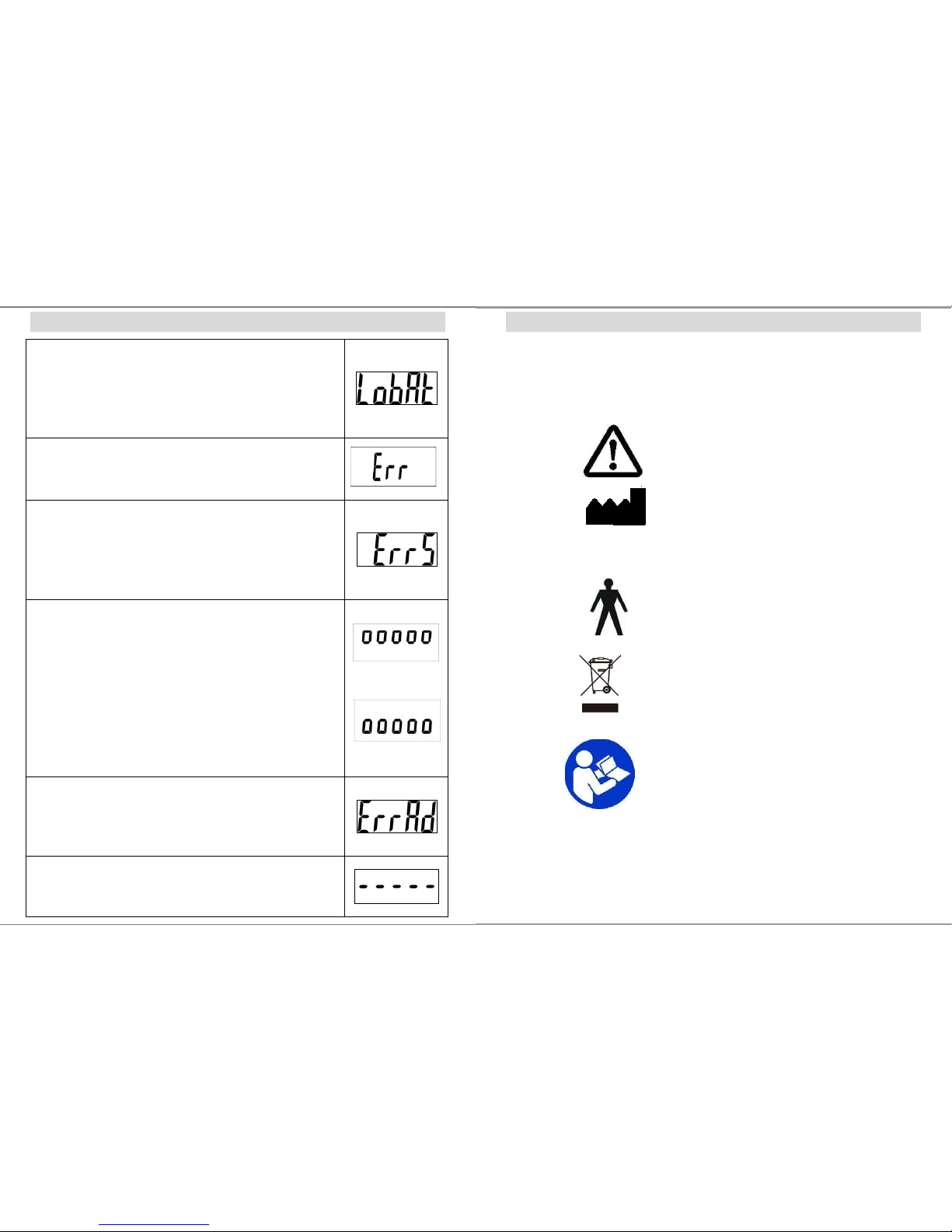
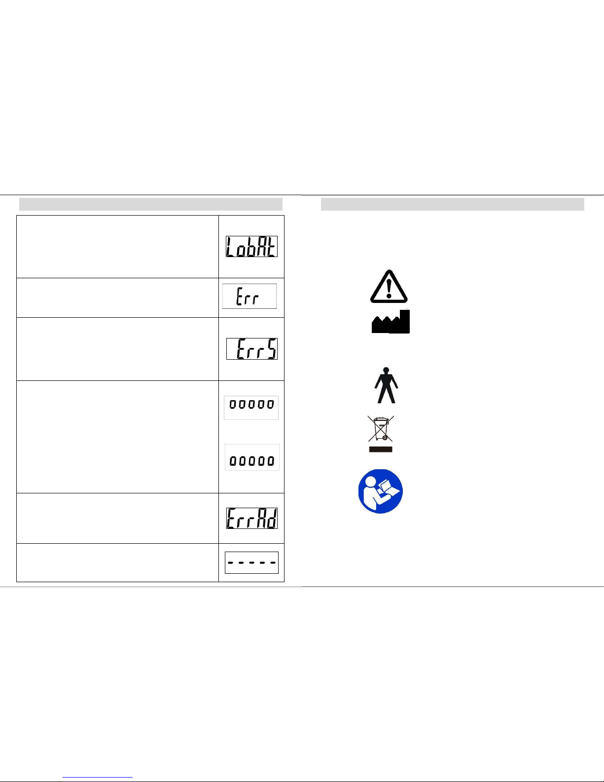
ERROR MESSAGE
Low Battery
1. Check battery voltage (>6.4V) and if needed replace new
battery for operation.
2. If the problem still persists inspect soldering of controller
PCB or replace the controller PCB.
Overload
This indicates that the scale’s load sensor(s) have been
overloaded. Reduce the loading and retry.
Counting Error
1. The signal from the load cells is too high or too low.
Please remove any weight from the scale and try to power on
again. If the scale continues to show the error message, it
indicates a fault with the electronics or wiring.
High/Low Zero Count
1. The scale is above its zero range. Please remove any
weight from the scale and power on again. If the scale
continues to show the error message, it indicates a fault with
the electronics.
2. The scale is below its zero range. Check there is nothing
jammed underneath the scale and power on again. If the
scale continues to show the error message, it indicates a fault
with the electronics.
AD Error
This indicates there is a fault with the scale’s software and is
normally caused by a fault with the PC board. Contact your
local service representative.
Negative weighing
When weight below -2kg, the display will shows “-----“.
Press ZERO to return to the normal mode.
7
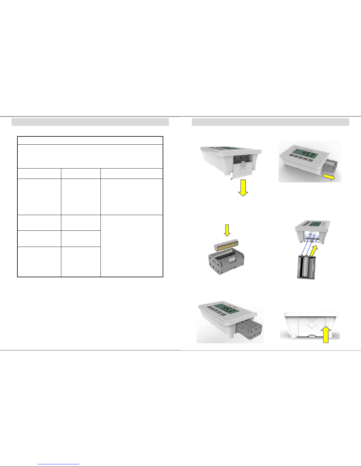
EXPLANATION OF THE GRAPHIC SYMBOLS
SN-T13000001
Designation of the serial number of
every device, applied at the device.
(Number as an example)
“Please note the accompanying
documents“
or “Observe operating instructions”
Charder Electronic Co., Ltd.
No.103, Guozhong Rd., Dali Dist.,
Taichung City 412, Taiwan (R.O.C.)
Identification of manufacturer of
medical product including address
“Type B applied part”
Dispose of old appliances
separately from your household
waste!l!
Instead, take them to communal
collection points.
Carefully read this operation manual
before setup and commissioning,
even if you are
already familiar with
Charder scales.
Page 8
8
EMC GUIDANCE AND MANUFACTURER'S DECLARATION
Guidance and manufacturer’s declaration-electromagnetic emissions
The MEDICAL SCALE MS3850 is intended for use in the electromagnetic
environment specified below.
The customer or the user of the MEDICAL SCALE MS3850 should assure
that it is used in such an environment.
Emission test Compliance
Electromagnetic
environment-guidance
RF emissions
CISPR 11
Group 1
The MEDICAL SCALE
MS3850 uses RF energy only
for its internal function.
Therefore, its RF emissions
are very low and are not likely
to cause any interference in
nearby electronic equipment.
RF emissions
CISPR 11
Class B
Harmonic emissions
IEC 61000-3-2
Class A
Voltage fluctuations
/flicker emissions
IEC 61000-3-3
Compliance
The MEDICAL SCALE
MS3850 is suitable for use in
all establishments, including
domestic establishments and
those directly connected to the
public low-voltage power
supply network that supplies
buildings used for domestic
purposes.
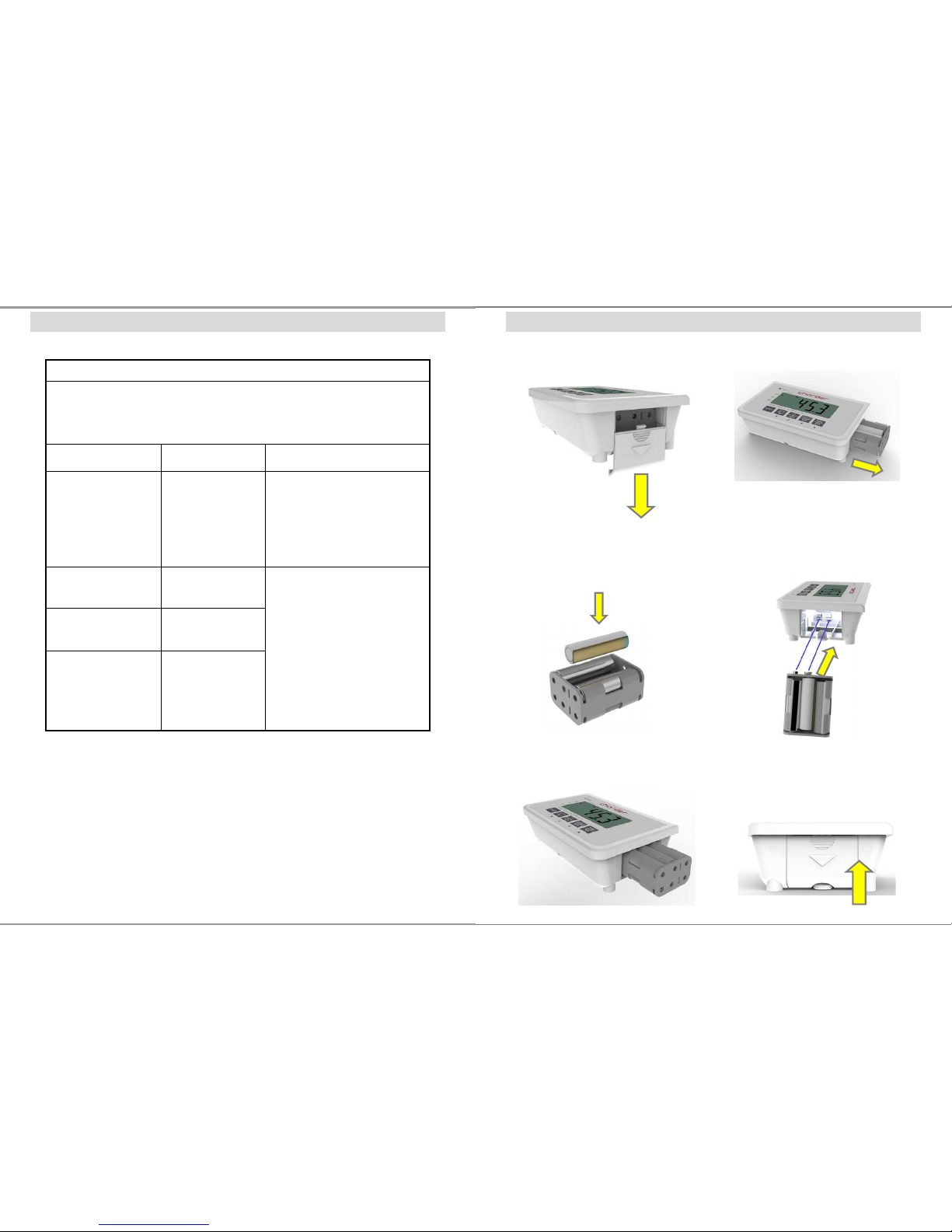
37
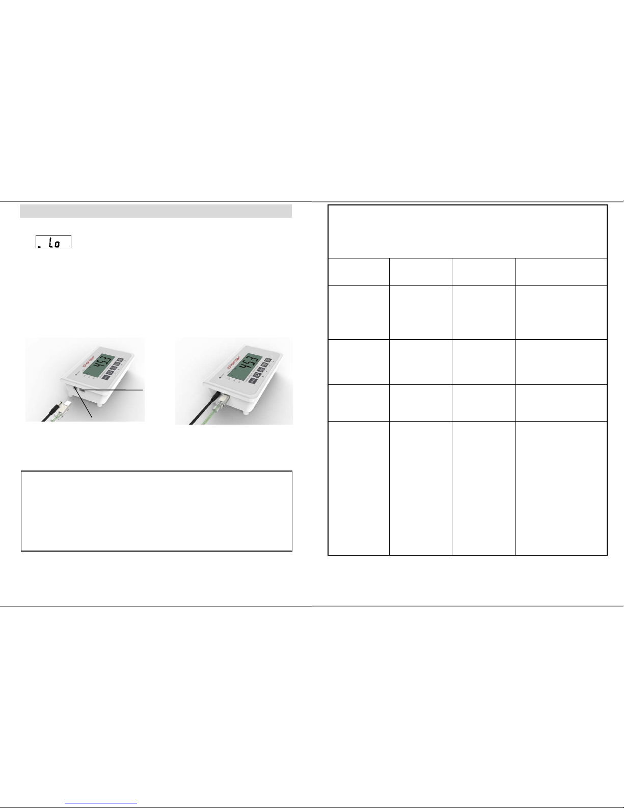
INSTRUCTION FOR REPLACING BATTERIES
1. Removing the battery cover. 2. Take out the battery housing.
3. Replacing new batteries. 4. Batteries are well installed.
5. Installing the battery housing. 6. Reinstalling the battery cover.
Page 9
36
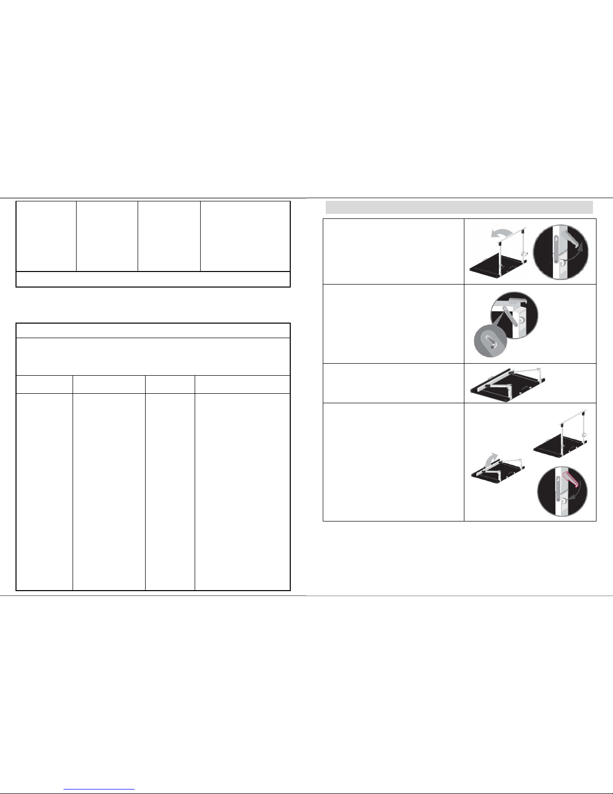
CAUTION:
Always connect the AC adaptor with the indicator before
connecting to the mains power supply.
Please disconnect the adaptor from main power supply
before taking out the AC adaptor pin from indicator.
INSTRUCTION FOR CHARGING AND CONNECTING
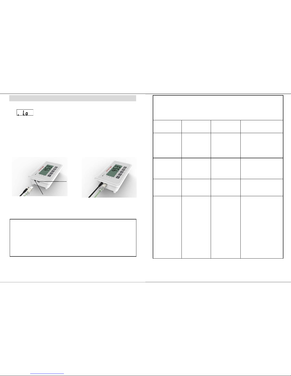
If
prompt displays on the LCD, please charge the
scale with MS3850 exclusive adaptor or replace the batteries.
Locate adaptor plug-in at the left side of indicator.
USB socket above USB symbol and you can connect USB cable
to transfer data.
Adaptor plug
USB port
9
Guidance and manufacturer’s declaration-electromagnetic immunity
The MEDICAL SCALE MS3850 is intended for use in the electromagnetic
environment specified below.
The customer or the user of the MEDICAL SCALE MS3850 should assure that it is
used in such an environment.
Immunity test
IEC 60601 test
level
Compliance
level
Electromagnetic
environment-guidance
Electrostatic
discharge(ESD)
IEC 61000-4-2
± 6 kV contact
± 8 kV air
± 6 kV contact
± 8 kV air
Floors should be wood,
concrete or ceramic tile.
If floors are covered with
synthetic material, the
relative humidity should
be at least 30%
Electrical fast
transient/burst
IEC 61000-4-4
± 2kV for power
supply lines +
1kV for
input/output
lines
± 2kV for power
supply lines Not
applicable
Mains power quality
should be that of a typical
commercial or hospital
environment.
Surge IEC
61000-4-5
± 1kV line(s) to
line(s) ± 2kV
line(s) to earth
± 1kV differential
mode Not
applicable
Mains power quality
should be that of a typical
commercial or hospital
environment.
Voltage Dips,
short
interruptions
and voltage
variations on
power supply
input lines IEC
61000-4-11
<5% UT(>95%
dip in UT) for 0,5
cycle 40%
UT(60% dip in
UT) for 5 cycles
70% UT(30%
dip in UT) for 25
cycles <5%
UT(>95% dip in
UT) for 5 s
<5% UT(>95%
dip in UT) for 0,5
cycle 40%
UT(60% dip in
UT) for 5 cycles
70% UT(30%
dip in UT) for 25
cycles <5%
UT(>95% dip in
UT) for 5 s
Mains power quality
should be that of a typical
commercial or hospital
environment. If the user
of the MEDICAL SCALE
MS3850 requires
continued operation
during power mains
interruptions, it is
recommended that the
MEDICAL SCALE
MS3850 be powered
from an uninterruptible
power supply or a
battery.
Page 10
10
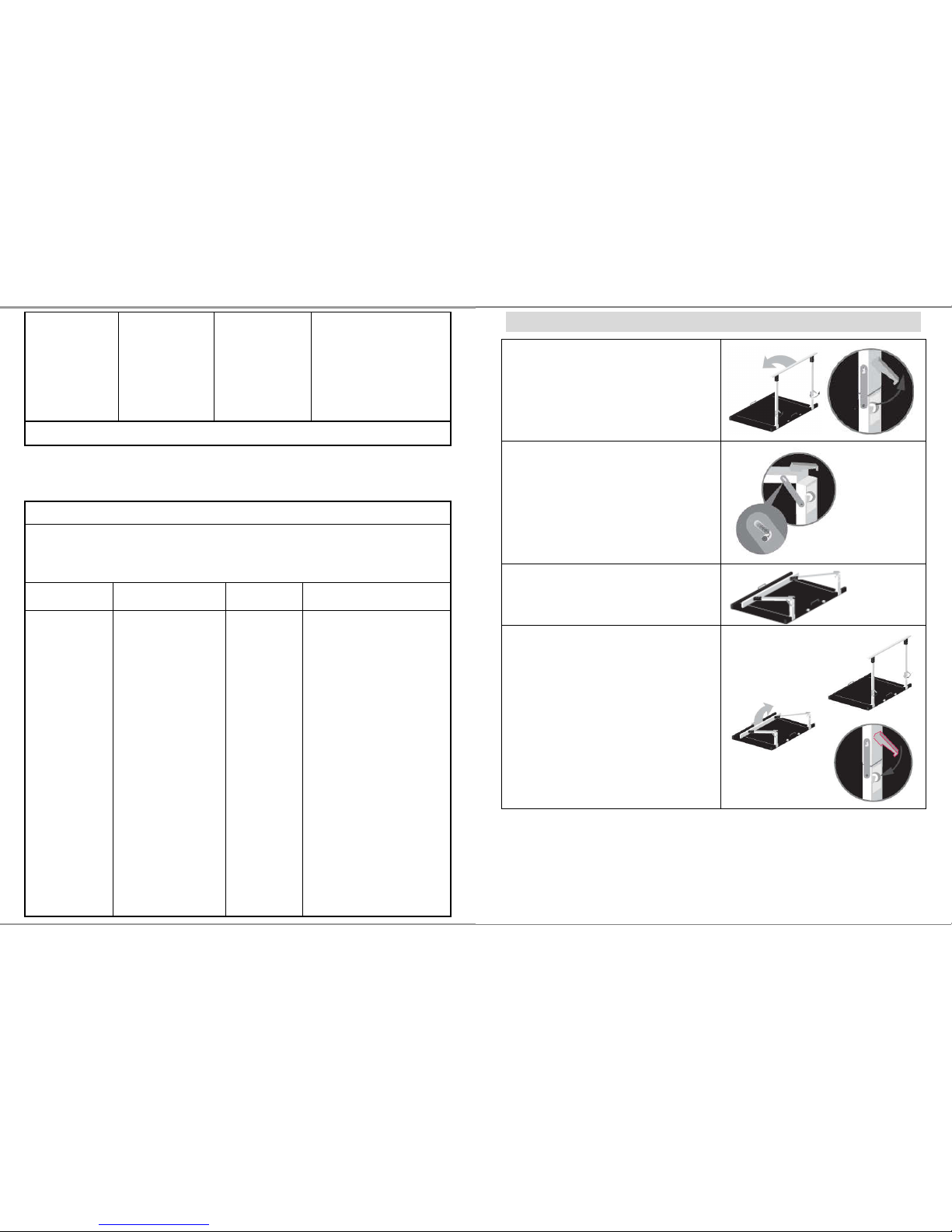
Power
frequency(50/60
Hz) magnetic
field IEC
61000-4-8
3 A/m 3 A/m
The MEDICAL SCALE
MS3850 power
frequency magnetic
fields should be at levels
characteristic of a typical
location in a typical
commercial or hospital
environment.
NOTE UT is the a.c. mains voltage prior to application of the test level.
Guidance and manufacturer’s declaration-electromagnetic immunity
The MEDICAL SCALE MS3850 is intended for use in the electromagnetic
environment specified below.
The customer or the user of the MEDICAL SCALE MS3850 should assure that is
used in such and environment.
Immunity test
IEC 60601 test
level
Compliance
level
Electromagnetic
environment-guidance
Conducted RF
IEC 61000-4-6
3 Vrms
150 KHz to 80 MHz
3 Vrms
Portable and mobile RF
communications equipment
should be used no closer to any
part of the
MEDICAL SCALE
MS3850 including cables, than
the recommended separation
distance calculated from the
equation applicable to the
frequency of the transmitter.
Recommended separation
distance:
d = 1,2 √P
d = 1,2 √P 80MHz to 800 MHz
d = 2,3 √P 800MHz to 2,5 GHz
Where P is the maximum output
power rating of the transmitter in
watts (W) according to the
transmitter manufacturer and d is
the recommended separation
distance in metres (m).
35
USING FOLDING FUNCTION
To fold the handrail down, release the
locking hook and carefully fold down
the handrail until it abuts completely.
The hinge will lock in place ready for
transportation.
To set the scale back up, place it on a
solid, level surface.
Raise the handrail until it is in an
upright position. Fix the locking
hooks on the hinge back in place, and
ensure the handrail is firmly in place.
Page 11
34
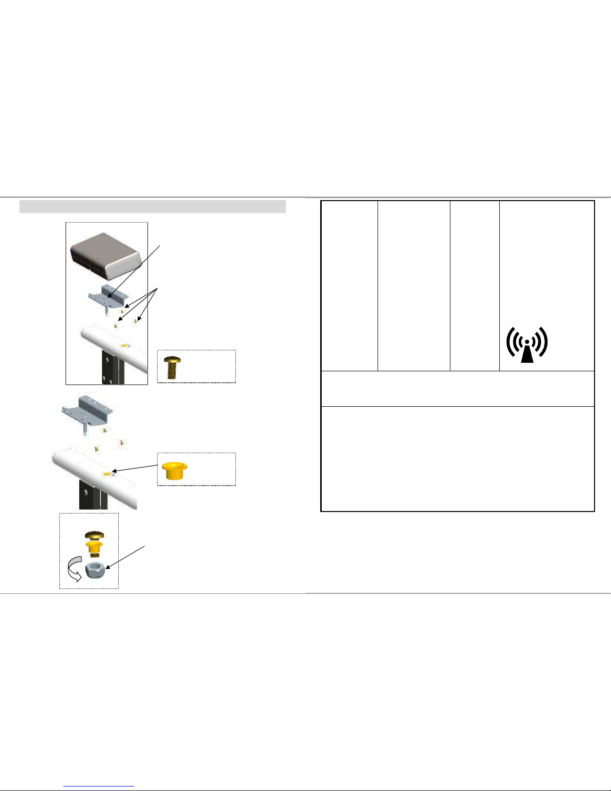
ASSEMBLY OF DISPLAY
M4*8 screw
Step 1.
Place a M4*8 screw in the center
of bracket
Step 2.
Fix display on the bracket with other
3pcs M4*8 screws
Step 4.
Tighten the nut with M4*8 screws
The display now can be swivel freely.
Step 3.
Place bearing in the handrail.
bearing
11
Radiated RF
IEC 61000-4-3
3 V/m 80MHz to 2,5
GHz
3 V/m
Field strengths from fixed RF
transmitters, as determined by an
electromagnetic site surveya,
should be less than the
compliance level in each
frequency range
b
.
Interference may occur in the
vicinity of equipment marked with
the following symbol:
NOTE1 At 80 MHz and 800 MHz, the higher frequency range applies.
NOTE2 These guidelines may not apply in all situations. Electromagnetic
propagation is affected by absorption and reflection from structures, objects and
people.
a Field strengths from fixed transmitters, such as base stations for radio
(cellular/cordless) telephones and land mobile radios, amateur radio, AM and
FM radio broadcast and TV broadcast cannot be predicted theoretically with
accuracy. To assess the electromagnetic environment due to fixed RF
transmitters, an electromagnetic site survey should be considered. If the
measured field strength in the location in which the MEDICAL SCALE MS3850
is used exceeds the applicable RF compliance level above, the MEDICAL
SCALE MS3850 should be observed to verify normal operation. If abnormal
performance is observed, additional measures my be necessary, such as
re-orienting or relocating the MEDICAL SCALE MS3850.
b Over the frequency range 150 kHz to 80 MHz, field strengths should be les than
3 V/m.
Page 12
12
Recommended separation distance between portable and mobile RF
communications equipment and the MEDICAL SCALE
The MEDICAL SCALE MS3850 is intended for use in an electromagnetic
environment in which radiated RF disturbances are controlled. The customer or
the user of the MEDICAL SCALE MS3850 can help prevent electromagnetic
interference by maintaining a minimum distance between portable and mobile
RF communications equipment (transmitters) and the MEDICAL SCALE
MS3850 as recommended below, according to the maximum output power of
the communications equipment.
Separation distance according to frequency of transmitter m
Rated maximum output
power of transmitter
W
150 kHz to 80 MHz
d =1,2√P
80 MHz to 800 MHz
d =1,2√P
800 MHz to 2,5 GHz
d =2,3√P
0,01 0,12 0,12 0,23
0,1 0,38 0,38 0,73
1 1,2 1,2 2,3
10 3,8 3,8 7,3
100 12 12 23
For transmitters rated at a maximum output power not listed above, the
recommended separation distance d in metres (m) can be estimated using the
equation applicable to the frequency of the transmitter, where p is the maximum
output power rating of the transmitter in watts (W) according to the transmitter
manufacturer.
NOTE1 At 80 MHz and 800 MHz, the separation distance for the higher
frequency range applies.
NOTE2 These guidelines may not apply in all situations. Electromagnetic
propagation is affected by absorption and reflection from structures, objects
and people.
33
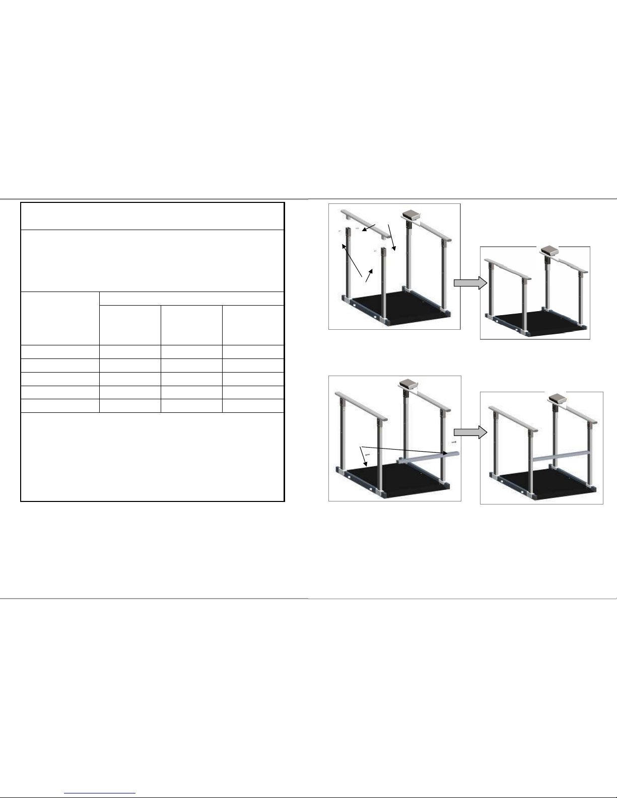
Step 5.
Assemble handrail bar.
Step 6.
Assemble cross bar(SS-8444) with two screws (M8-1.25P*45)
no.5
no.3
Screws
Page 13
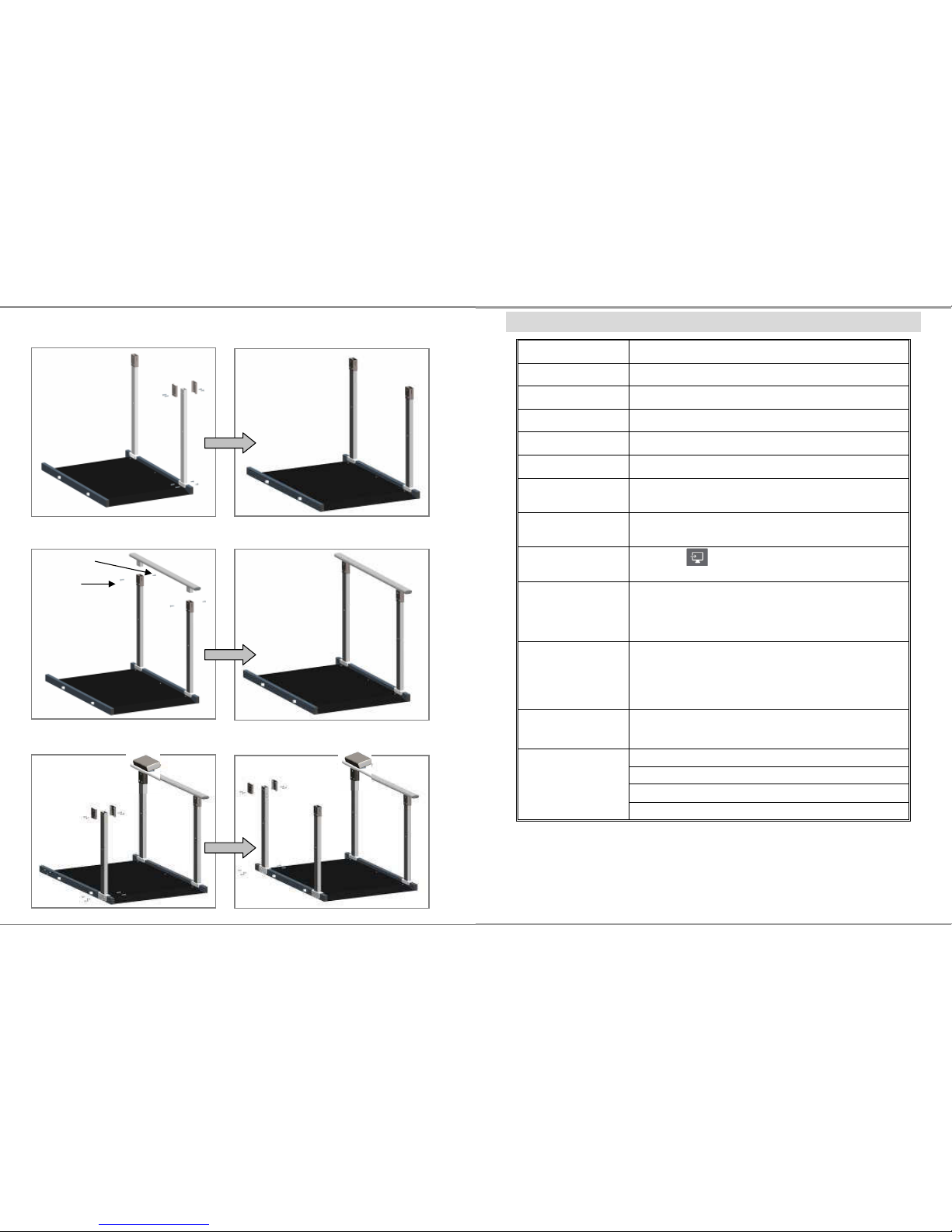
32
Step 2.
Assemble pole on platform. Same as step1.
Step 3.
Assemble handrail bar with poles.
Step 4.
Assemble third pole and fourth pole on platform.
no.3
no.5
13
SPECIFICATION
Model MS 3850
Capacity 300kg x 0.1kg
Accuracy ±0.2kg
Weight Unit Kg, lb
LCD Display 1.4 inch LCD display with 5 digits
Dimension 1150(L) x 800(W) x 66(H) mm
Operating Temp.
and Humidity
5°C - 35°C
15% - 85% RH
Transport / Storage
Temp, and Humidity
- 20°C … + 60°C
10% - 95% RH
Key Functions
UNIT , SEND, ON/OFF/ZERO, HOLD/BMI,
TARE/BSA
Power Supply
6-AA size batteries
12V AC Adaptor
Standard
Accessories
Adjustable Feet x 2 ; spacer x 2; Fixed plate (top) x
1.;Fixed plate (bottom) x 1;Tapping Screw x 3; User
manual x 1; USB cable x 1; 12V Adaptor x 1; Plastic
anchor x 2, Screw x 2
Options SM2711 indicator stand
Foldable handrail set SM-00001
Handrail set right side SM-3461
Handrail set left side SM-3462
Cross bar set SS-8444
Page 14
14
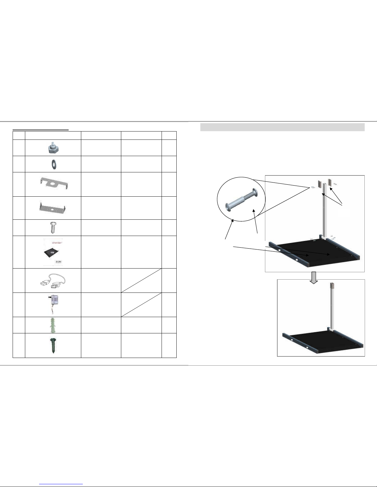
Standard Accessories
No.
Accessories
Item Spec. Qty.
1
Adjustable feet
M6*15
2
2
Spacer
∮6.6*∮13
2
3
Fixed plate (top)
SS-4961 1
4
Fixed plate
(bottom)
SS-4971 1
5
Tapping screw
M3*10 3
6
User manual CD-IN-00052 1
7
USB cable 1
8
12V Adaptor 1
9
Plastic anchor
1”(white) 2
10
Screw 4*20 2
31
ASSEMBLY INSTRUCTION OF HANDRAILS
Step 1.
Fix no.2 (fixing plate) on the pole with wiring duct with no.3 (socket
screw) and no.5 (screw nut).
Fix pole with wiring duct on platform by using no.3 and no.5.
no.5
no.3
no.2
Page 15
30
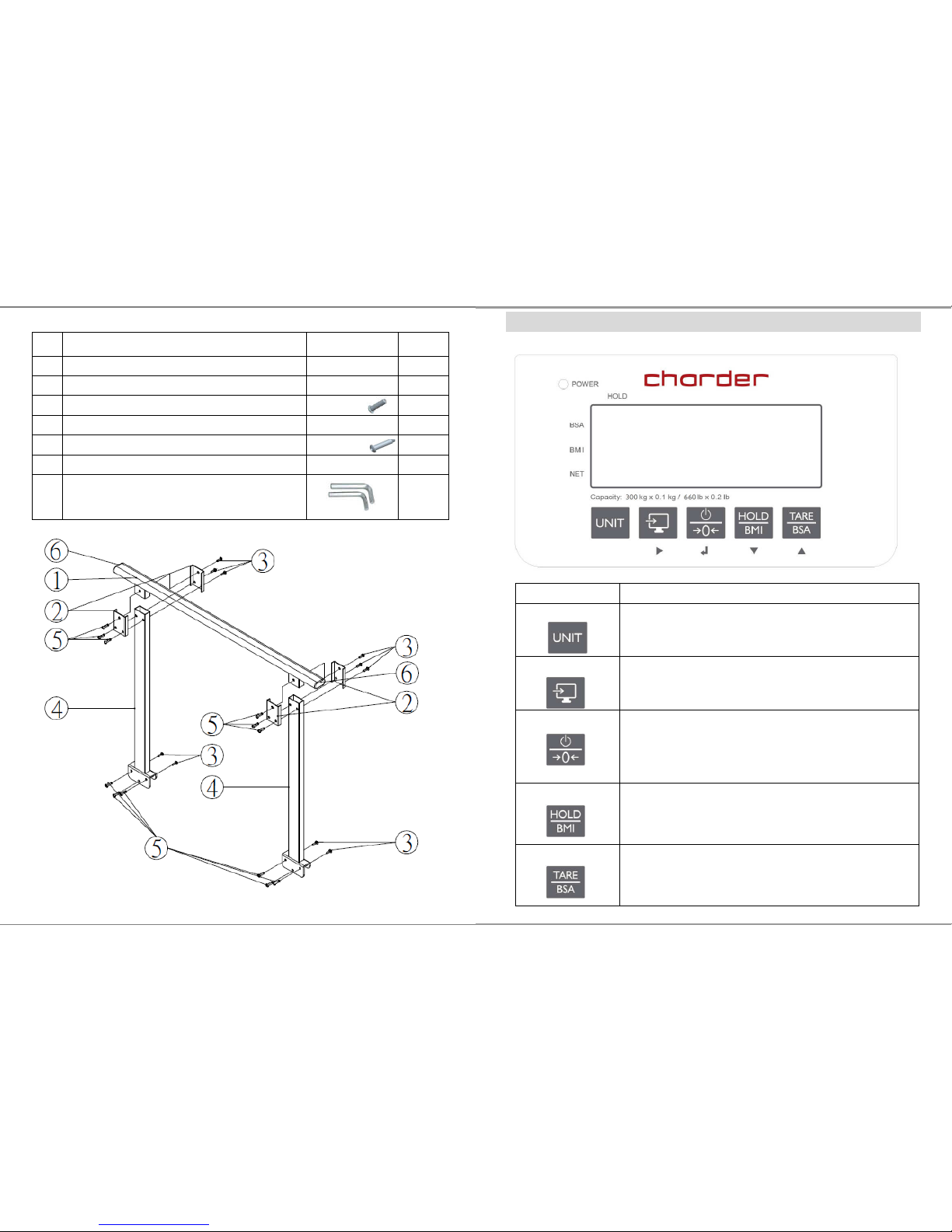
SM-3462 (L)
NO.
Item Drawing Qty.
1.
Handrail bar without screw hole SS-8300A 1
2.
Fixing plate SS-8311 4
3.
Socket button head cap screw
M6-21
10
4.
Pole AM-8173 2
5.
Socket button head cap screw nut
ø8-M6*33
12
6.
Rubber end cap SW-8068 2
Socket key
2
15
PANEL
Operation keys Functions
UNIT
Change unit key.
Press to switch measuring unit from kg and lb
SEND
Send data key.
Press to send measuring data to PC
ON/OFF/ZERO
Switch on and off.
Press button to turn it on. To turn it off, press and
hold the button for 1 second
Press once to set the scale to zero when scale is on
HOLD/BMI
Enable HOLD and BMI function
Press once to enable weight lock function
Press button and hold 3 secs to enable BMI mode
TARE/BSA
Press once to enable TARE function
When BMI is activated. Press TARE/BSA button to
display BSA[body surface area]
Page 16
16
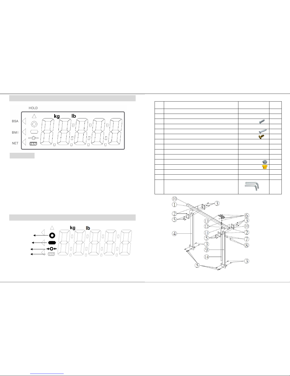
LCD SYMBOL DESCRIPTION
Definitions
Stable symbol: To indicate that the weight is stable.
Minor weight: Weight under zero.
Zero symbols: Weight is at zero point.
Low battery: Battery need to charge or replaced.
BSA : Body surface area is activated
BMI : Body Mass Index is activated
NET : Net weight appears after press tare button
HOLD : Weight lock function is activated
SYMBOLS Information
Stability sign
Negative sign
Zero indication
Battery symbol
29
SM-3461 (R)
NO.
Item Drawing Qty.
1.
Handrail bar SS-8300B 1
2.
Fixing plate SS-8311 4
3.
Socket button head cap screw
M6-21
10
4.
Pole AM-8173 1
5.
Socket button head cap screw nut
ø8-M6*33
12
6.
Screw for display set
M4*8
4
7. Screw nut for printer bracket
(installed already)
M5-0.8-JB 2
8.
Plastic screw (installed already)
M5-0.8*8
2
9.
Pole with wiring duct AM-8173A 1
10.
Rubber end cap SW-8068 2
11.
Locking nut M8*1.25*8 1
12.
Bearing SF-1F-08075 2
13.
Bracket SS-8303 1
14.
Wiring duct TC-2WE 100cm 1
Socket key
2
Page 17
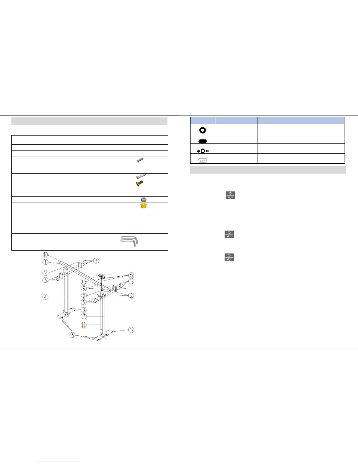
28
PARTS LIST OF SM-00001 SM-3461(R) & SM-3462(L)
SM-00001 Foldable handrail
NO.
Item Drawing Qty.
1.
Handrail bar SS-8300B 1
2.
Fixing plate SS-8311 4
3.
Socket button head cap screw
M6-21
10
4.
Pole
AM-2681 with
AM-2691
1
5.
Socket button head cap screw nut
ø8-M6*33
12
6.
Screw for display set
M4*8
3
7.
Pole with wiring duct
AM-2682 with
AM-2691
1
8.
Locking nut
M8*1.25*8
1
9.
Bearing
SF-1F-08075
2
10.
Bracket
SS-8303A for DP44
SS-8303 for
DP37
1
11.
Wiring duct TC-2WE 100cm 1
12
Socket key
M5
2
17
Operation
1 Switching on/off
Switching on
Press to switch scale on
For a few seconds the devices shows a start-up screen with the
full segmental LCD display, software version and then 0.0 kg
Switching off
Press and hold for 3 seconds to switch scale off
Zero the scale
Press while scale is on to zeroing the scale
2 Straight weighing
1. Place weighing object/person on the scale
2. Wait until the stability sign appears
3. Read the weighing result
3 Weighing with hold
This device is provided with the integrated hold function (determination of average
value). It enables people to be weighed accurately although they are not still on the
scale plate. Once the HOLD key is pressed, the weight reading will remain on the
display after the item has been removed from the scale so the reading can easily be
read.
Symbol Information Remark
Stability sign
Mark appears when weight is stable
Negative sign
When weight value is negative
Zero indication
When scale is set to zero
Battery symbol
Indicate 5 level of battery power.
Page 18
18
Note
Determination of average value is not possible when a person moves too much.
HOLD function won’t work if the weight is under 2 kg.
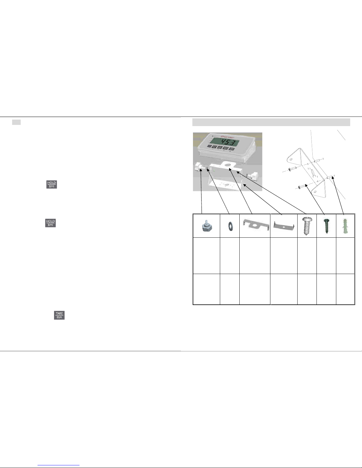
1. Switch on the scale. The diagnostic self-checks is performed. The
scale is ready for weighing when the „0.0 kg” displays on the
screen.
2. Place object/person on the scale.
3. Press key. When the triangle is flashing on the display,
the scale records the fluctuating weight values and then
calculates average weight and displays the result on the screen.
4. Remove object/person from the scale. The weight reading will
remain on the display.
5. Press key again to return the scale to the normal weighing
mode.
6. HOLD function can be activated before or after place the weight
on the SCALE.
4 Weighing with tare
Tare function allows the user to deduct the excess weight of a single tare object
value (additional loads or clothes) from the display reading, thus calculate the
actual net weight of the object/ person.
4.1.1 Taring
Place tare object (additional loads or clothes) on scale and
press to tare the weight of object.
The zero display and the symbol NET appear.
The tare weight remains stored until it is cleared.
27
ASSEMBLY OF BRACKET
Adjustable
feet
Spacer
Fixed plate
(top)
Fixed plate
(bottom)
Tapping
Screw
Screw
Plastic
anchor
2 2 1 1 2 2 2
Wall
Page 19
26
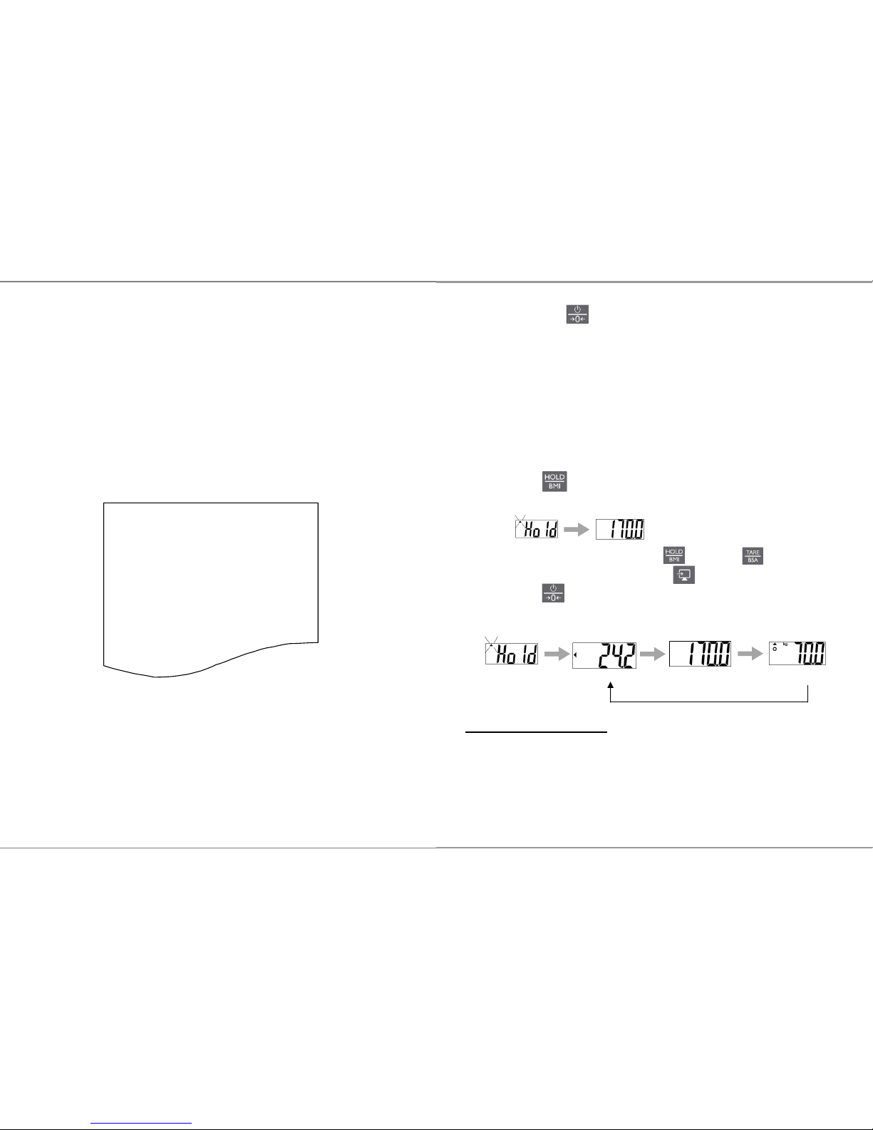
8. Printout Data Through USB cable connector
Click OK button to complete the setting. The PC will retrieve the
weighing & BMI data from the CHARDER scale and display on the
HyperTerminal program similar to the layout below.
While the Hyper Terminal program is running, type “P” KEY on the PC
keyboard to transmit a print command to printout from the thermal
printer on the CHARDER scale for hard copy of weighing data & BMI.
Or, press the [PRINT] button on the display panel of the CHARDER
scale, the printout presented below is the standard format print layout
as well as shown on the HyperTerminal computer screen.
GROSS WEIGHT 70.00kg
TARE WEIGHT 0.00kg
NET WEIGHT 0.00kg
USER HEIGHT 170.0cm
USER B.M.I. 24.2
01/01/2013 10:00
19
4.1.2 Clear the tare
Press to clear tare weight
The symbol NET disappear
The gross weight appears in the display.
5 Weighing with BMI
For BMI calculation, height is needed, therefore it is recommended to measure the
height of subject before starting weighing procedure.
1. Switch on the scale.
2. Place object/person on the scale.
3. Press key and hold for 3 seconds. First, display will show
“HOLD” and lock weight then display show “height value”.
4. Adjust height value by using (↓) and (↑) keys.
5. Switch between digits by using (→) key.
6. Press to confirm height value.
7. Display will show “HOLD” and lock weight to calculate BMI.
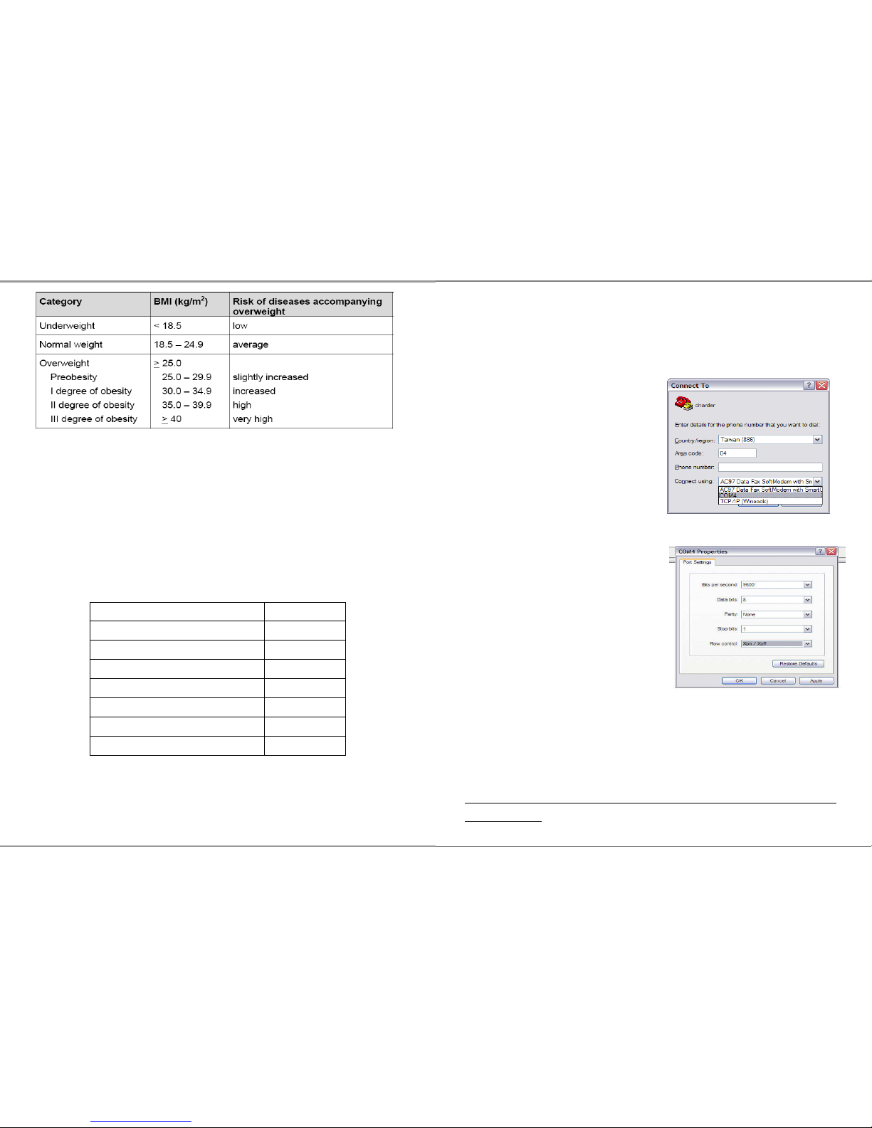
Body Mass Index Categories
Classification of weight for adults over 18 years on the basis of Body Mass Index
according to WHO, 2000 EK IV and WHO 2004 (WHO - World Health Organization).
BMI
Height
weight
Page 20
20
6 Weighing with BSA
- Values for Body surface area (BSA) is the measured or calculated surface area of a
human body. For many clinical purposes BSA is a better indicator of metabolic mass
than body weight because it is less affected by abnormal adipose mass. BSA are
commonly used in medicine, particularly to calculate doses of chemotherapeutic
agents and index cardiac output.
Average BSA for children of various ages, for men, and for women, are taken to
be:
Age BSA
Neonate (newborn) 0.25 m²
Child of 2 years 0.5 m²
9 years 1.07 m²
10 years 1.14 m²
12-13 years 1.33 m²
Women 1.6 m²
Men 1.9 m²
There was an average BSA of 1.73 m² for 3,000 cancer patients from 1990 to 1998 in a European
Organisation for Research and Treatment of Cancer (EORTC) database.
25
6. Select COM Port on User PC
Click Connect to select COM port on the computer. Then click OK.
7. Port Settings for Printout
Set up as below:
Baud rate: 9600 bps
Parity check: None
Data length: 8 bits
Stop bit: 1 bit
Handshake: RTS/CTS
Data code: ASCII
USB Driver Install
The scale confirms to the USB PL2303
Make sure the computer software has a USB scale interface.
PL2303 driver download:
http://www.prolific.com.tw/US/ShowProduct.aspx?pcid=41&showlevel=0
017-0037-0041
Page 21
24
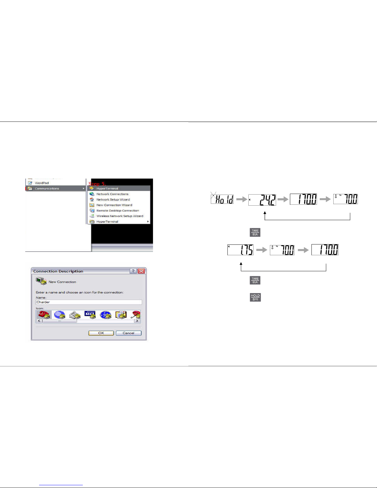
PC’s Windows OS with the following steps:
Step.1- Click on Start Button.
Step.2- Go to All Programs.
Step.3- Select Accessories.
Step.4- Find Communications.
Step.5- In Communications section click on HyperTerminal.
5. New Connection Description
Name the connection and click OK Button
21
During 2005 there was an average BSA of 1.79 m² for 3,613 adult cancer patients in the UK. Among
them the average BSA for men was 1.91 m² and for women was 1.71 m².
However, there is some evidence that BSA values are less accurate at extremes of height and weight,
where Body Mass Index may be a better estimate.
6.1.1 Enable BSA in BMI mode
1. Starting with BMI process
2. When BMI, weight and height is playing rotationally.
3. Press to play BSA value.
4. Press to return to BMI mode.
5. Press to return to normal mode.
BMI
Height
weight
Height
weight
BSA
Page 22
22
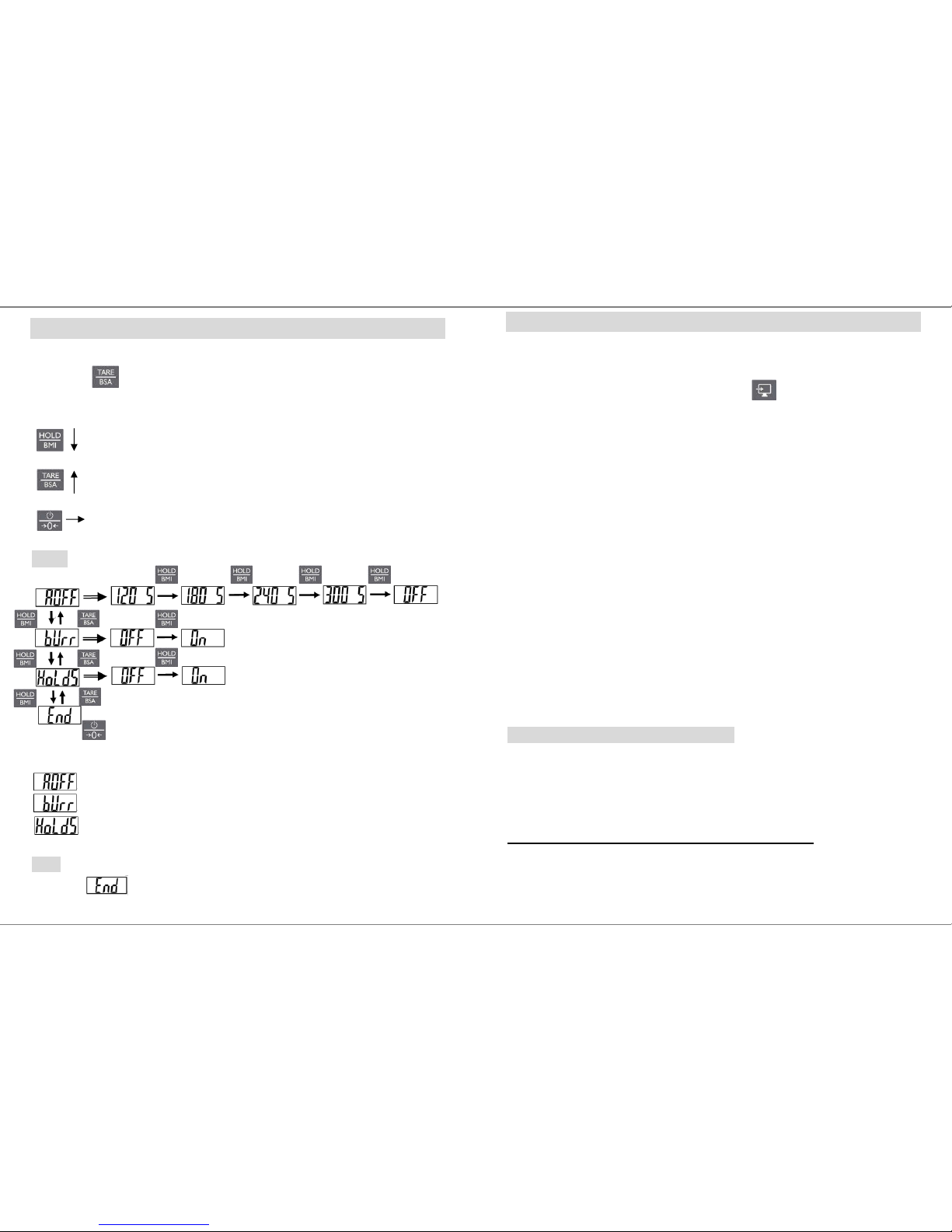
SETTING-UP MS3850
1. Switch on the scale.
2. Press key and hold for 6 seconds to enable setting mode.
3. LCD shows “SETUP” first and then “A.OFF” appears.
Switch between modes and menu
Reverse switch between modes and menu
Confirm setting.
MENU
AUTO-OFF TIME SETUP
This enables operator to select the auto turn OFF time of the device.
BUZZER ON/OFF SETUP
Set auto-off timer between 120/180/240/300/off
Set buzzer on and off
Set HOLD function release after unload weight ON and OFF.
Note
Confirm in the menu to save all settings.
23
PRINT function and data transmission
The Weighing, BMI and Height results can be keep in PC for records using USB interface
cable, which is connected to the USB plug at the back terminal.
After complete BMI and BSA process, simply press key to transfer the results to
PC.
HOW TO SETUP USB CONNECTIONS ON PC
1. Make sure the PC hardware device has USB port version2.0 or above
compatibility. Users may need to consult with local computer
accessories dealer to select the proper USB cable length that is most
suitable to work environment for best performance, then connect the
cable first between the PC and CHARDER Scale model.
2. Run HyperTerminal program under Windows OS computer and input
printer port parameter settings, please refer to the next Section in
<Step 7> on how to setup HyperTerminal program in user’s computer
for printer port parameters.
3. Once the HyperTerminal setting is ready, make sure the USB cable is
connected properly between the user PC’s USB port and the CHARDER
Scale Model again. Press PRINT button on the Scale Display Panel for
printout of weight & BMI data from thermal printer.
Hyper Terminal setting in PC for printout
Hyper Terminal is a freeware on PC Windows XP SP3 or lower to setup the
PC printer com-port with USB cable connector transmission.
For use on Windows Vista or higher please download hyper terminal
software program from Charder website:
http://www.chardermedical.com/download/dlist-4.htm
4. Start Hyper Terminal
After taking the weight and BMI, run Hyper Terminal program from the
Page 23
44
Manufactured by:
Charder Electronic Co., Ltd.
No.103, Guozhong Rd., Dali Dist.,
Taichung City 412, Taiwan (R.O.C.)
CD-IN-00052 [REV0002] 07/2018
1
Please keep the instruction manual at hand all the time for future reference
MS 3850
Medical Scale
USER MANUAL
Page 24

2
TABLE OF CONTENTS
PREFACE.....................................................................................................3
GENERAL INFORMATION....................................................................... 3
SAFETY INSTRUCTION ...........................................................................3
ENVIROMENTAL....................................................................................... 4
CLEANING.................................................................................................. 4
MAINTENANCE......................................................................................... 4
WEIGHING OPERATION ..........................................................................5
WARRANTY-LIABILITY........................................................................... 5
DISPOSING OF THE SCALE..................................................................... 6
EXPLANATION OF THE GRAPHIC SYMBOLS.....................................7
EMC GUIDANCE AND MANUFACTURER'S DECLARATION ............ 8
SPECIFICATION .......................................................................................13
PANEL........................................................................................................15
LCD SYMBOL DESCRIPTION................................................................16
SYMBOLS Information............................................................................. 16
Operation.................................................................................................... 17
SETTING-UP MS3850..............................................................................22
PRINT function and data transmission.......................................................23
ASSEMBLY OF BRACKET......................................................................27
PARTS LIST OF SM-00001 SM-3461(R) & SM-3462(L)........................28
ASSEMBLY INSTRUCTION OF HANDRAILS .....................................31
ASSEMBLY OF DISPLAY........................................................................34
USING FOLDING FUNCTION................................................................ 35
INSTRUCTION FOR CHARGING AND CONNECTING......................36
INSTRUCTION FOR REPLACING BATTERIES...................................37
ERROR MESSAGE................................................................................... 38
TROUBLESHOOTING.............................................................................39
43
NOTE
Page 25
42
NOTE
3
PREFACE
Thank you for choosing CHARDER MEDICAL product. All features
of this product were designed to state of the art and are optimized for
simple and straightforward use. If you have any queries or
experience any problems not addressed in the operating instructions,
please contact your CHARDER MEDICAL service partner, or visit us
on the Internet at www.chardermedical.com
GENERAL INFORMATION
We strongly recommend you use the scales on flat and hard surface.
Any soft surface, like carpet will cause inaccuracy.
SAFETY INSTRUCTION
Before putting the device into use, please read with care the
information given in the Operating Instructions. They contain
important instructions for installation, proper use and
maintenance of the device.
The manufacturer shall not be liable for damages arising out of
failure to heed the following instructions:
These batteries should be kept away from small children. If
swallowed, promptly seek medical assistance.
Expected Service Life: 5 years
When using electrical components under increased safety
requirements, always comply with the appropriate regulations.
Improper installation will render the warranty null and void.
Ensure the voltage marked on the power supply unit matches
your main power supply.
This device is designed for use indoors.
Observe the permissible ambient temperatures for use
The device meets the requirements for electromagnetic
compatibility. Do not exceed the maximum values specified in
the applicable standards.
If you have any question, contact your local CHARDER MEDICAL
service partner.
Page 26

4
ENVIROMENTAL
All batteries contain toxic compounds; disposal of batteries should
be delegated to a competent organisation, complying with the
deposit of Poisonous Waste Regulation 1972.
Please do not incinerate batteries.
The optimum operating temperature for the scale is 5℃ to +35℃;
although it will operate at higher and lower temperatures the
scales battery life will be adversely effected.
CLEANING
We would recommend using alcohol based wipes or similar
when cleaning the scales.
Please do not use large amounts of water when cleaning the
scales as this will cause damage to the scales electronics, you
should also refrain from using corrosive liquids or high pressure
washers.
Always disconnect the scales from the mains power supply
before cleaning.
MAINTENANCE
The scale does not require any routine maintenance. However,
we recommend checking the scale’s accuracy at regular intervals.
The regularity of these checks is dependent on the level of use and
the state of the scale. If any inaccuracies occur, please contact
your local dealer or CHARDER MEDICAL service partner.
41
display screen & texts color blurred, smeared rainbow screen,
incorrect decimal display
LCD PIN broken or short circuit
PCB cooper foil broken & loosed welding
Unable to save or read data – IC or transistor faulty, internal parts
broken.
LCD showing “ERRL” after switch on - Load cell damaged
Overload may cause the weigh to malfunction.
Software system crash
Resonator faulty
Load cells with faulty grinding standard.
Key buttons failure - Front key panel damaged or disconnected
3. Buzzer malfunction
Wrong welding of PVC wire
Key buttons & control panel damaged or disconnected.
Page 27

40
2. Indicator showing “0000” ZERO SPAN out of range
Incorrect weighing result - Avoid damages by external
environment force such as free-drop to the ground, collision by
external objects, etc.
Proper re-calibration procedure required to correct the setting of
weighing accuracy.
Interference due to RF disturbance, ground vibration…etc.
Unstable platform feet adjustments according to bubble level
indication
Incorrect position or other external objects within weighing area
The weighing-scale is not put in a solid & firm ground area, such
as carpet floor or lawn.
3. Connection failure for data transmission to PC or printer
Wrong connection wires or faulty wires for transmission between
the digital indicator & load cells.
Wrong indicator models
Wrong internal wiring or wire broken
In case of the following defective mode occurs, it is suggested to contact
your nearest Authorized Dealer for further technician service & repair:
1. POWER switch-on failure :
Push-button faulty
Short circuit wires - Wire broken
Safety fuse burnt out
Wire connection problem
Main power adaptor faulty – Parts Replacement
2. LCD display faulty
Possible hardware defects include: Uneven brightness in the LCD
5
WEIGHING OPERATION
Before reading detailed instructions on how to use all the weighing
functions that are built into your scale, please read the following
important guidelines:
Always be sure that the display shows `Zero` before use, if it does
not then please press the ZERO key.
The device is designed to detect when a stable weight is achieved,
the indicator will `bleep` twice to indicate a stable weight value, your
reading should be taken at this point.
WARRANTY-LIABILITY
If a fault or defect is present on receipt of the unit which is within
CHARDER MEDICAL’s scope of responsibility, CHARDER shall
have the right to either repair the fault or supply a replacement unit.
Replaced parts shall be the property of CHARDER. Should the fault
repairs or replacement delivery not be successful, the statutory
provisions shall be valid. The period of warranty shall be two years,
beginning on the date of purchase. Please retain your receipt as
proof of purchase. Should your scale require servicing, please
contact your dealer or CHARDER MEDICAL Customer Service.
No responsibility shall be accepted for damage caused through any
of the following reasons: Unsuitable or improper storage or use,
incorrect installation or commissioning by the owner or third parties,
natural wear, changes or modifications, incorrect or negligent
handling, overuse, chemical, electrochemical or electrical
interference or humidity, unless this is attributable to negligence on
the part of CHARDER MEDICAL.
If operating, climatic or any other influences lead to a major change
in conditions or material quality, the treaty for perfect unit
Page 28

6
functioning shall be rendered null and void. If CHARDER provides
and individual warranty, this means that the unit supplied will be free
of faults for the length of the warranty period.
DISPOSING OF THE SCALE
This product is not to be treated as regular household waste, but
should be handed in to an electrical/electronic equipment recycling
centre.
You can obtain further details from your local council, your
municipal waste disposal company or the firm which you purchased
the product.
39
TROUBLESHOOTING
Troubleshooting for defective modes:
Original purchaser can enjoy the benefits under the effective Warranty
against functional defects in material and workmanship subject to the
terms and conditions listed in the yearly Warranty Program & Return
Policy.
Our warranty service program includes the following:
1. Technician repair service under warranty or at a service
maintenance charge depending on the workmanship for the
defective functionality or cause of damage covered by the
warranty.
2. Parts replacement from the manufacturing factory under the
warranty or at a certain cost for the replaced parts plus the
workmanship charge if not covered under the warranty.
Before you contact our Authorized Dealer in your country for technician
repair service, please read through the following section carefully:
Self-checking Tips:
Some functional defects can be identified and maintained by
users as listed below:
1. Power-on failure
Check if the main power adaptor has not plugged onto the scale
properly
Check if the battery power is running low - Replace with new
batteries
Page 29
38
ERROR MESSAGE
Low Battery
1. Check battery voltage (>6.4V) and if needed replace new
battery for operation.
2. If the problem still persists inspect soldering of controller
PCB or replace the controller PCB.
Overload
This indicates that the scale’s load sensor(s) have been
overloaded. Reduce the loading and retry.
Counting Error
1. The signal from the load cells is too high or too low.
Please remove any weight from the scale and try to power on
again. If the scale continues to show the error message, it
indicates a fault with the electronics or wiring.
High/Low Zero Count
1. The scale is above its zero range. Please remove any
weight from the scale and power on again. If the scale
continues to show the error message, it indicates a fault with
the electronics.
2. The scale is below its zero range. Check there is nothing
jammed underneath the scale and power on again. If the
scale continues to show the error message, it indicates a fault
with the electronics.
AD Error
This indicates there is a fault with the scale’s software and is
normally caused by a fault with the PC board. Contact your
local service representative.
Negative weighing
When weight below -2kg, the display will shows “-----“.
Press ZERO to return to the normal mode.
7
EXPLANATION OF THE GRAPHIC SYMBOLS
SN-T13000001
Designation of the serial number of
every device, applied at the device.
(Number as an example)
“Please note the accompanying
documents“
or “Observe operating instructions”
Charder Electronic Co., Ltd.
No.103, Guozhong Rd., Dali Dist.,
Taichung City 412, Taiwan (R.O.C.)
Identification of manufacturer of
medical product including address
“Type B applied part”
Dispose of old appliances
separately from your household
waste!l!
Instead, take them to communal
collection points.
Carefully read this operation manual
before setup and commissioning,
even if you are
already familiar with
Charder scales.
Page 30
8
EMC GUIDANCE AND MANUFACTURER'S DECLARATION
Guidance and manufacturer’s declaration-electromagnetic emissions
The MEDICAL SCALE MS3850 is intended for use in the electromagnetic
environment specified below.
The customer or the user of the MEDICAL SCALE MS3850 should assure
that it is used in such an environment.
Emission test Compliance
Electromagnetic
environment-guidance
RF emissions
CISPR 11
Group 1
The MEDICAL SCALE
MS3850 uses RF energy only
for its internal function.
Therefore, its RF emissions
are very low and are not likely
to cause any interference in
nearby electronic equipment.
RF emissions
CISPR 11
Class B
Harmonic emissions
IEC 61000-3-2
Class A
Voltage fluctuations
/flicker emissions
IEC 61000-3-3
Compliance
The MEDICAL SCALE
MS3850 is suitable for use in
all establishments, including
domestic establishments and
those directly connected to the
public low-voltage power
supply network that supplies
buildings used for domestic
purposes.
37
INSTRUCTION FOR REPLACING BATTERIES
1. Removing the battery cover. 2. Take out the battery housing.
3. Replacing new batteries. 4. Batteries are well installed.
5. Installing the battery housing. 6. Reinstalling the battery cover.
Page 31
36
CAUTION:
Always connect the AC adaptor with the indicator before
connecting to the mains power supply.
Please disconnect the adaptor from main power supply
before taking out the AC adaptor pin from indicator.
INSTRUCTION FOR CHARGING AND CONNECTING
If
prompt displays on the LCD, please charge the
scale with MS3850 exclusive adaptor or replace the batteries.
Locate adaptor plug-in at the left side of indicator.
USB socket above USB symbol and you can connect USB cable
to transfer data.
Adaptor plug
USB port
9
Guidance and manufacturer’s declaration-electromagnetic immunity
The MEDICAL SCALE MS3850 is intended for use in the electromagnetic
environment specified below.
The customer or the user of the MEDICAL SCALE MS3850 should assure that it is
used in such an environment.
Immunity test
IEC 60601 test
level
Compliance
level
Electromagnetic
environment-guidance
Electrostatic
discharge(ESD)
IEC 61000-4-2
± 6 kV contact
± 8 kV air
± 6 kV contact
± 8 kV air
Floors should be wood,
concrete or ceramic tile.
If floors are covered with
synthetic material, the
relative humidity should
be at least 30%
Electrical fast
transient/burst
IEC 61000-4-4
± 2kV for power
supply lines +
1kV for
input/output
lines
± 2kV for power
supply lines Not
applicable
Mains power quality
should be that of a typical
commercial or hospital
environment.
Surge IEC
61000-4-5
± 1kV line(s) to
line(s) ± 2kV
line(s) to earth
± 1kV differential
mode Not
applicable
Mains power quality
should be that of a typical
commercial or hospital
environment.
Voltage Dips,
short
interruptions
and voltage
variations on
power supply
input lines IEC
61000-4-11
<5% UT(>95%
dip in UT) for 0,5
cycle 40%
UT(60% dip in
UT) for 5 cycles
70% UT(30%
dip in UT) for 25
cycles <5%
UT(>95% dip in
UT) for 5 s
<5% UT(>95%
dip in UT) for 0,5
cycle 40%
UT(60% dip in
UT) for 5 cycles
70% UT(30%
dip in UT) for 25
cycles <5%
UT(>95% dip in
UT) for 5 s
Mains power quality
should be that of a typical
commercial or hospital
environment. If the user
of the MEDICAL SCALE
MS3850 requires
continued operation
during power mains
interruptions, it is
recommended that the
MEDICAL SCALE
MS3850 be powered
from an uninterruptible
power supply or a
battery.
Page 32
10
Power
frequency(50/60
Hz) magnetic
field IEC
61000-4-8
3 A/m 3 A/m
The MEDICAL SCALE
MS3850 power
frequency magnetic
fields should be at levels
characteristic of a typical
location in a typical
commercial or hospital
environment.
NOTE UT is the a.c. mains voltage prior to application of the test level.
Guidance and manufacturer’s declaration-electromagnetic immunity
The MEDICAL SCALE MS3850 is intended for use in the electromagnetic
environment specified below.
The customer or the user of the MEDICAL SCALE MS3850 should assure that is
used in such and environment.
Immunity test
IEC 60601 test
level
Compliance
level
Electromagnetic
environment-guidance
Conducted RF
IEC 61000-4-6
3 Vrms
150 KHz to 80 MHz
3 Vrms
Portable and mobile RF
communications equipment
should be used no closer to any
part of the
MEDICAL SCALE
MS3850 including cables, than
the recommended separation
distance calculated from the
equation applicable to the
frequency of the transmitter.
Recommended separation
distance:
d = 1,2 √P
d = 1,2 √P 80MHz to 800 MHz
d = 2,3 √P 800MHz to 2,5 GHz
Where P is the maximum output
power rating of the transmitter in
watts (W) according to the
transmitter manufacturer and d is
the recommended separation
distance in metres (m).
35
USING FOLDING FUNCTION
To fold the handrail down, release the
locking hook and carefully fold down
the handrail until it abuts completely.
The hinge will lock in place ready for
transportation.
To set the scale back up, place it on a
solid, level surface.
Raise the handrail until it is in an
upright position. Fix the locking
hooks on the hinge back in place, and
ensure the handrail is firmly in place.
Page 33
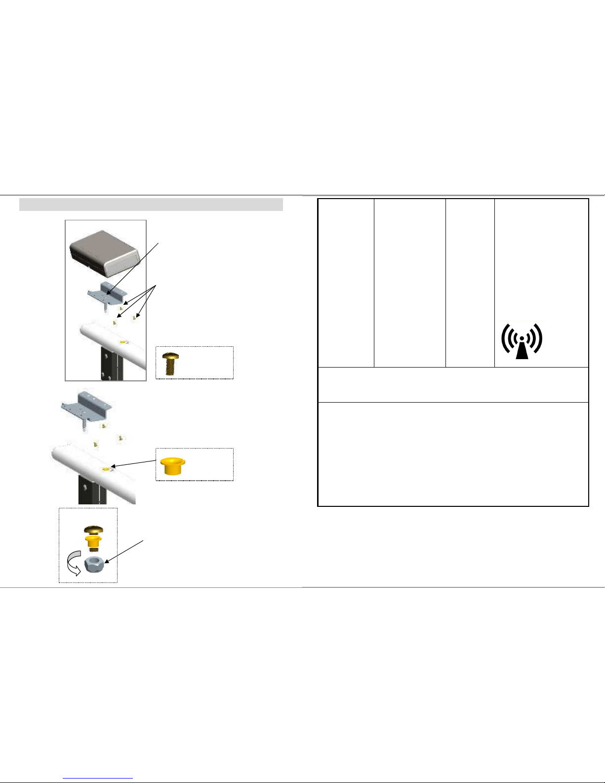
34
ASSEMBLY OF DISPLAY
M4*8 screw
Step 1.
Place a M4*8 screw in the center
of bracket
Step 2.
Fix display on the bracket with other
3pcs M4*8 screws
Step 4.
Tighten the nut with M4*8 screws
The display now can be swivel freely.
Step 3.
Place bearing in the handrail.
bearing
11
Radiated RF
IEC 61000-4-3
3 V/m 80MHz to 2,5
GHz
3 V/m
Field strengths from fixed RF
transmitters, as determined by an
electromagnetic site surveya,
should be less than the
compliance level in each
frequency range
b
.
Interference may occur in the
vicinity of equipment marked with
the following symbol:
NOTE1 At 80 MHz and 800 MHz, the higher frequency range applies.
NOTE2 These guidelines may not apply in all situations. Electromagnetic
propagation is affected by absorption and reflection from structures, objects and
people.
a Field strengths from fixed transmitters, such as base stations for radio
(cellular/cordless) telephones and land mobile radios, amateur radio, AM and
FM radio broadcast and TV broadcast cannot be predicted theoretically with
accuracy. To assess the electromagnetic environment due to fixed RF
transmitters, an electromagnetic site survey should be considered. If the
measured field strength in the location in which the MEDICAL SCALE MS3850
is used exceeds the applicable RF compliance level above, the MEDICAL
SCALE MS3850 should be observed to verify normal operation. If abnormal
performance is observed, additional measures my be necessary, such as
re-orienting or relocating the MEDICAL SCALE MS3850.
b Over the frequency range 150 kHz to 80 MHz, field strengths should be les than
3 V/m.
Page 34
12
Recommended separation distance between portable and mobile RF
communications equipment and the MEDICAL SCALE
The MEDICAL SCALE MS3850 is intended for use in an electromagnetic
environment in which radiated RF disturbances are controlled. The customer or
the user of the MEDICAL SCALE MS3850 can help prevent electromagnetic
interference by maintaining a minimum distance between portable and mobile
RF communications equipment (transmitters) and the MEDICAL SCALE
MS3850 as recommended below, according to the maximum output power of
the communications equipment.
Separation distance according to frequency of transmitter m
Rated maximum output
power of transmitter
W
150 kHz to 80 MHz
d =1,2√P
80 MHz to 800 MHz
d =1,2√P
800 MHz to 2,5 GHz
d =2,3√P
0,01 0,12 0,12 0,23
0,1 0,38 0,38 0,73
1 1,2 1,2 2,3
10 3,8 3,8 7,3
100 12 12 23
For transmitters rated at a maximum output power not listed above, the
recommended separation distance d in metres (m) can be estimated using the
equation applicable to the frequency of the transmitter, where p is the maximum
output power rating of the transmitter in watts (W) according to the transmitter
manufacturer.
NOTE1 At 80 MHz and 800 MHz, the separation distance for the higher
frequency range applies.
NOTE2 These guidelines may not apply in all situations. Electromagnetic
propagation is affected by absorption and reflection from structures, objects
and people.
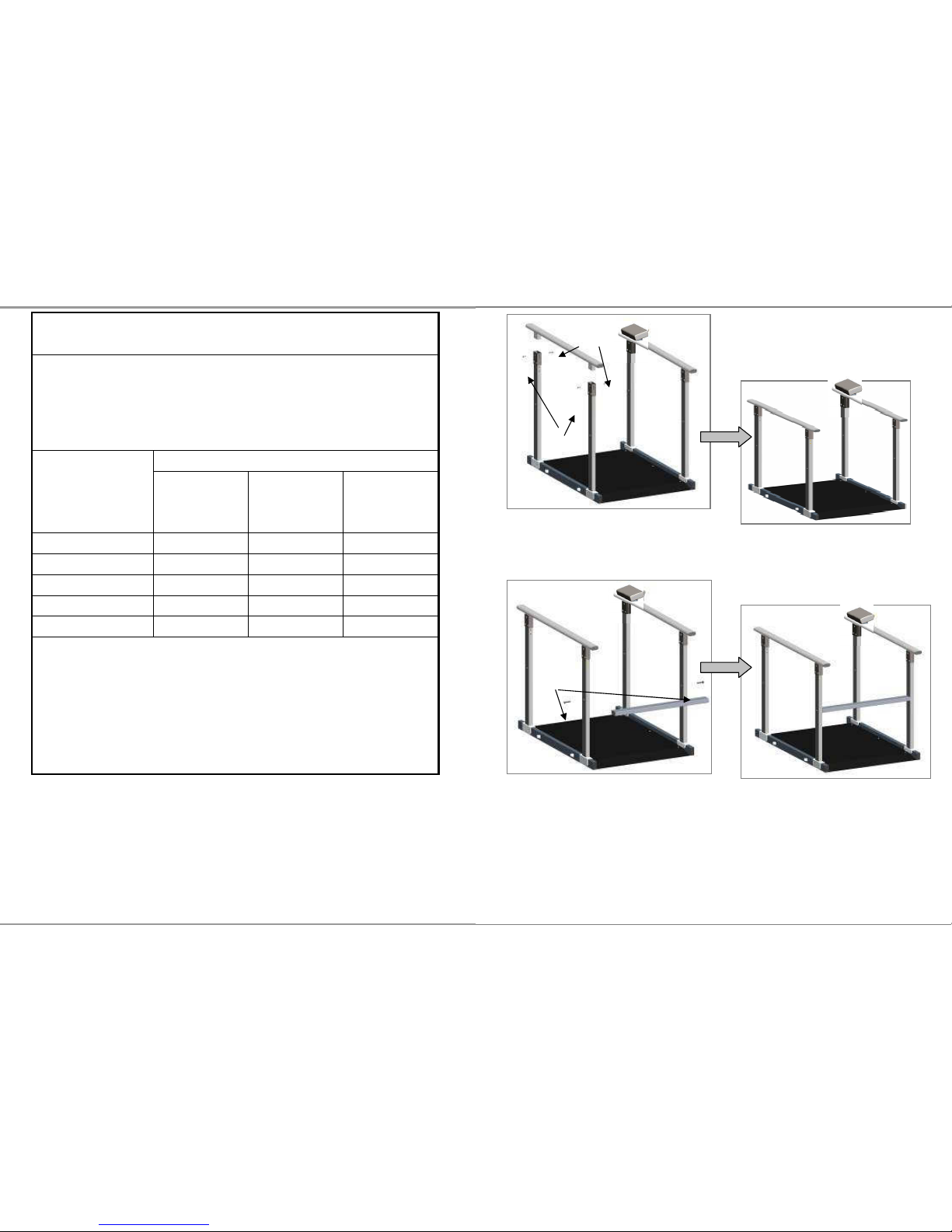
33
Step 5.
Assemble handrail bar.
Step 6.
Assemble cross bar(SS-8444) with two screws (M8-1.25P*45)
no.5
no.3
Screws
Page 35
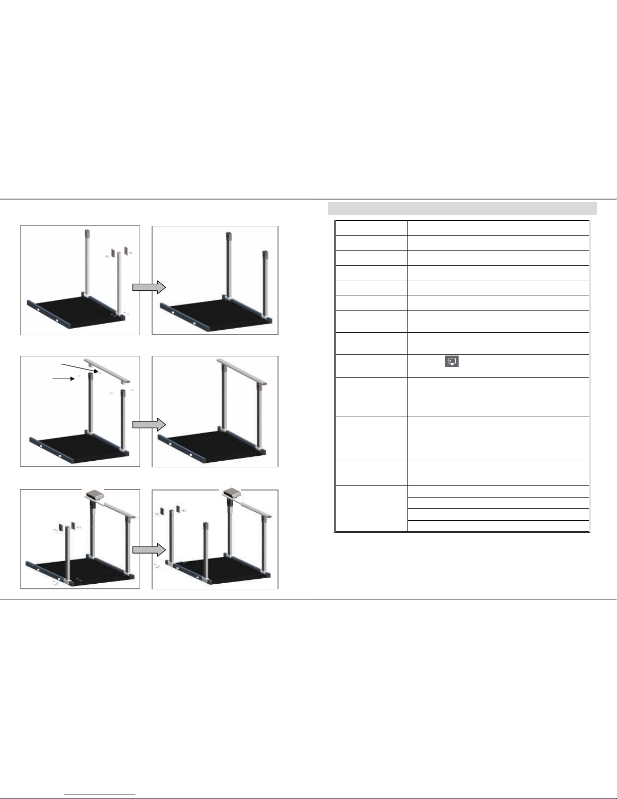
32
Step 2.
Assemble pole on platform. Same as step1.
Step 3.
Assemble handrail bar with poles.
Step 4.
Assemble third pole and fourth pole on platform.
no.3
no.5
13
SPECIFICATION
Model MS 3850
Capacity 300kg x 0.1kg
Accuracy ±0.2kg
Weight Unit Kg, lb
LCD Display 1.4 inch LCD display with 5 digits
Dimension 1150(L) x 800(W) x 66(H) mm
Operating Temp.
and Humidity
5°C - 35°C
15% - 85% RH
Transport / Storage
Temp, and Humidity
- 20°C … + 60°C
10% - 95% RH
Key Functions
UNIT , SEND, ON/OFF/ZERO, HOLD/BMI,
TARE/BSA
Power Supply
6-AA size batteries
12V AC Adaptor
Standard
Accessories
Adjustable Feet x 2 ; spacer x 2; Fixed plate (top) x
1.;Fixed plate (bottom) x 1;Tapping Screw x 3; User
manual x 1; USB cable x 1; 12V Adaptor x 1; Plastic
anchor x 2, Screw x 2
Options SM2711 indicator stand
Foldable handrail set SM-00001
Handrail set right side SM-3461
Handrail set left side SM-3462
Cross bar set SS-8444
Page 36
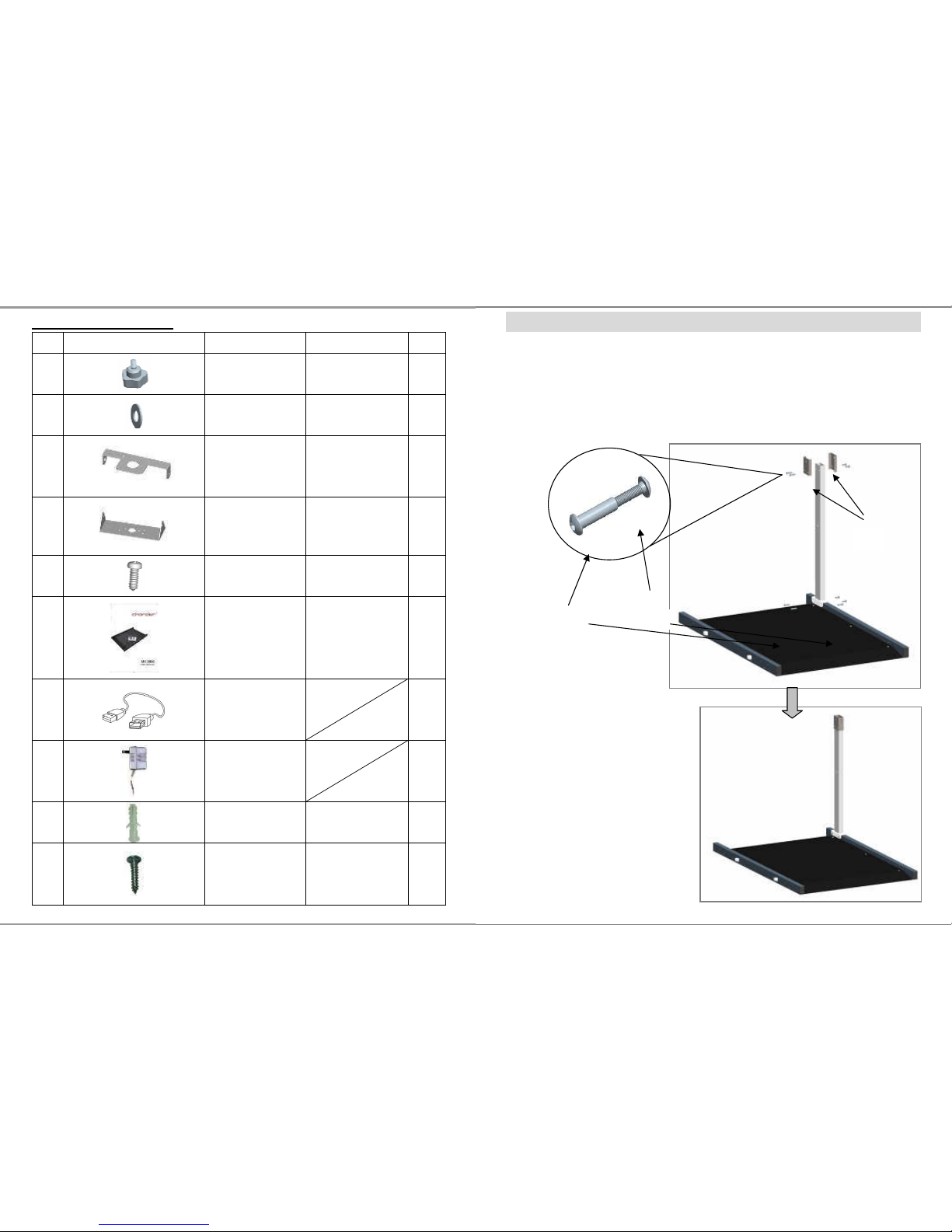
14
Standard Accessories
No.
Accessories
Item Spec. Qty.
1
Adjustable feet
M6*15
2
2
Spacer
∮6.6*∮13
2
3
Fixed plate (top)
SS-4961 1
4
Fixed plate
(bottom)
SS-4971 1
5
Tapping screw
M3*10 3
6
User manual CD-IN-00052 1
7
USB cable 1
8
12V Adaptor 1
9
Plastic anchor
1”(white) 2
10
Screw 4*20 2
31
ASSEMBLY INSTRUCTION OF HANDRAILS
Step 1.
Fix no.2 (fixing plate) on the pole with wiring duct with no.3 (socket
screw) and no.5 (screw nut).
Fix pole with wiring duct on platform by using no.3 and no.5.
no.5
no.3
no.2
Page 37
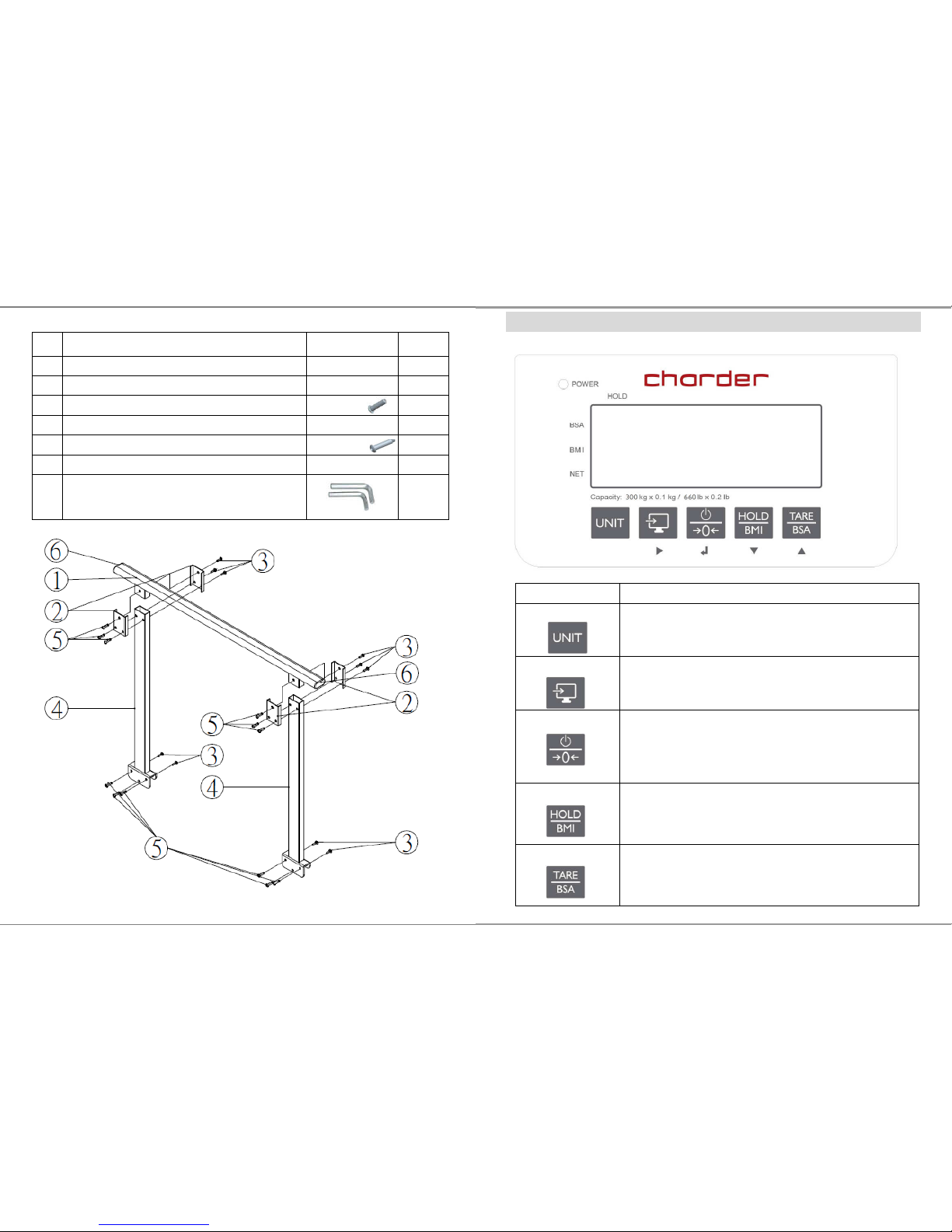
30
SM-3462 (L)
NO.
Item Drawing Qty.
1.
Handrail bar without screw hole SS-8300A 1
2.
Fixing plate SS-8311 4
3.
Socket button head cap screw
M6-21
10
4.
Pole AM-8173 2
5.
Socket button head cap screw nut
ø8-M6*33
12
6.
Rubber end cap SW-8068 2
Socket key
2
15
PANEL
Operation keys Functions
UNIT
Change unit key.
Press to switch measuring unit from kg and lb
SEND
Send data key.
Press to send measuring data to PC
ON/OFF/ZERO
Switch on and off.
Press button to turn it on. To turn it off, press and
hold the button for 1 second
Press once to set the scale to zero when scale is on
HOLD/BMI
Enable HOLD and BMI function
Press once to enable weight lock function
Press button and hold 3 secs to enable BMI mode
TARE/BSA
Press once to enable TARE function
When BMI is activated. Press TARE/BSA button to
display BSA[body surface area]
Page 38
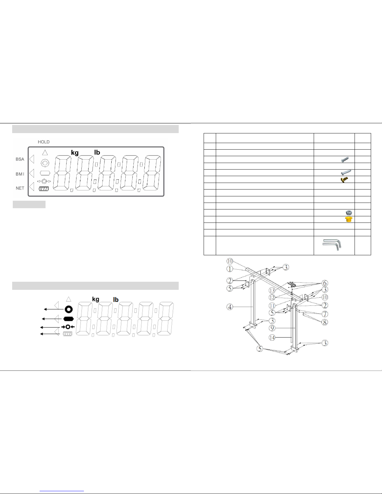
16
LCD SYMBOL DESCRIPTION
Definitions
Stable symbol: To indicate that the weight is stable.
Minor weight: Weight under zero.
Zero symbols: Weight is at zero point.
Low battery: Battery need to charge or replaced.
BSA : Body surface area is activated
BMI : Body Mass Index is activated
NET : Net weight appears after press tare button
HOLD : Weight lock function is activated
SYMBOLS Information
Stability sign
Negative sign
Zero indication
Battery symbol
29
SM-3461 (R)
NO.
Item Drawing Qty.
1.
Handrail bar SS-8300B 1
2.
Fixing plate SS-8311 4
3.
Socket button head cap screw
M6-21
10
4.
Pole AM-8173 1
5.
Socket button head cap screw nut
ø8-M6*33
12
6.
Screw for display set
M4*8
4
7. Screw nut for printer bracket
(installed already)
M5-0.8-JB 2
8.
Plastic screw (installed already)
M5-0.8*8
2
9.
Pole with wiring duct AM-8173A 1
10.
Rubber end cap SW-8068 2
11.
Locking nut M8*1.25*8 1
12.
Bearing SF-1F-08075 2
13.
Bracket SS-8303 1
14.
Wiring duct TC-2WE 100cm 1
Socket key
2
Page 39
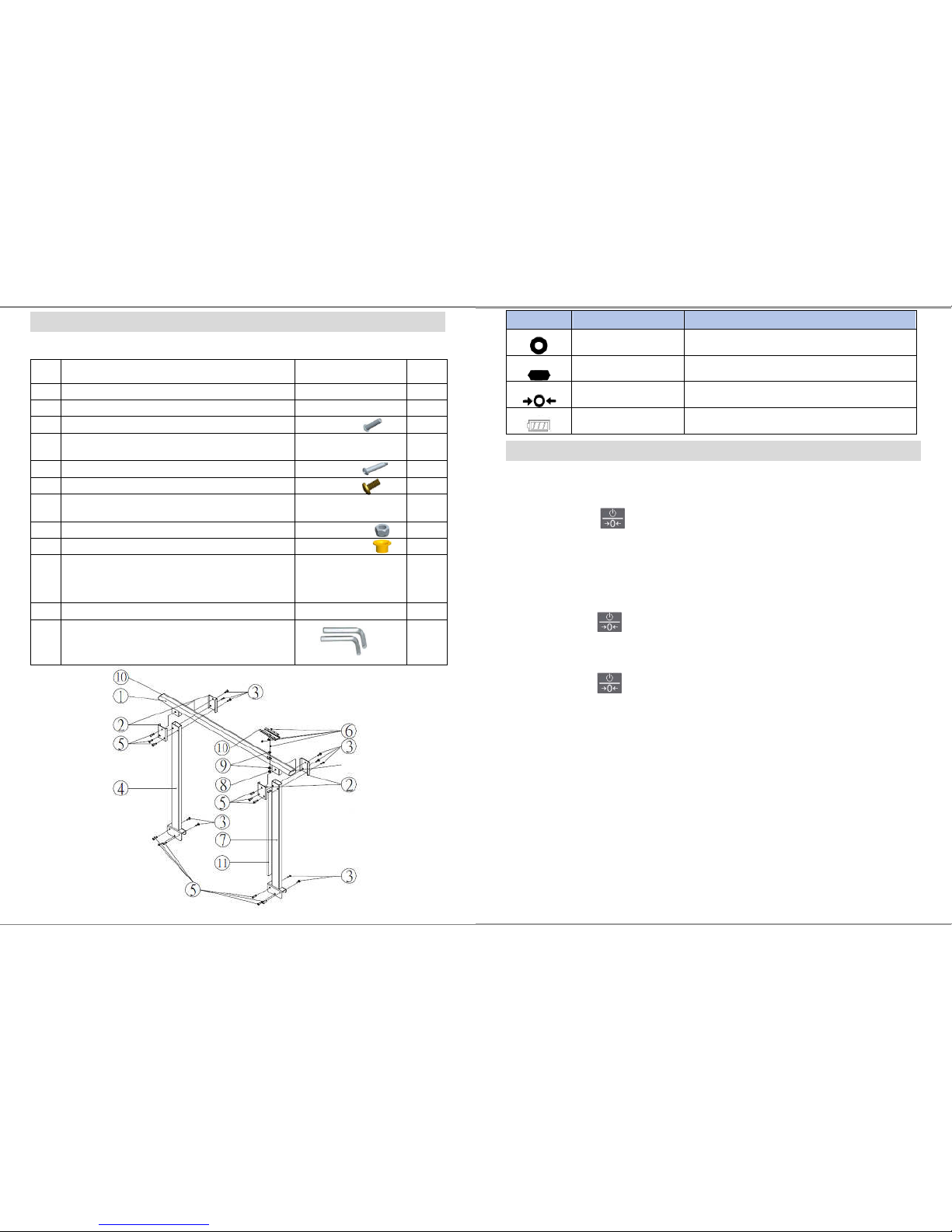
28
PARTS LIST OF SM-00001 SM-3461(R) & SM-3462(L)
SM-00001 Foldable handrail
NO.
Item Drawing Qty.
1.
Handrail bar SS-8300B 1
2.
Fixing plate SS-8311 4
3.
Socket button head cap screw
M6-21
10
4.
Pole
AM-2681 with
AM-2691
1
5.
Socket button head cap screw nut
ø8-M6*33
12
6.
Screw for display set
M4*8
3
7.
Pole with wiring duct
AM-2682 with
AM-2691
1
8.
Locking nut
M8*1.25*8
1
9.
Bearing
SF-1F-08075
2
10.
Bracket
SS-8303A for DP44
SS-8303 for
DP37
1
11.
Wiring duct TC-2WE 100cm 1
12
Socket key
M5
2
17
Operation
1 Switching on/off
Switching on
Press to switch scale on
For a few seconds the devices shows a start-up screen with the
full segmental LCD display, software version and then 0.0 kg
Switching off
Press and hold for 3 seconds to switch scale off
Zero the scale
Press while scale is on to zeroing the scale
2 Straight weighing
1. Place weighing object/person on the scale
2. Wait until the stability sign appears
3. Read the weighing result
3 Weighing with hold
This device is provided with the integrated hold function (determination of average
value). It enables people to be weighed accurately although they are not still on the
scale plate. Once the HOLD key is pressed, the weight reading will remain on the
display after the item has been removed from the scale so the reading can easily be
read.
Symbol Information Remark
Stability sign
Mark appears when weight is stable
Negative sign
When weight value is negative
Zero indication
When scale is set to zero
Battery symbol
Indicate 5 level of battery power.
Page 40
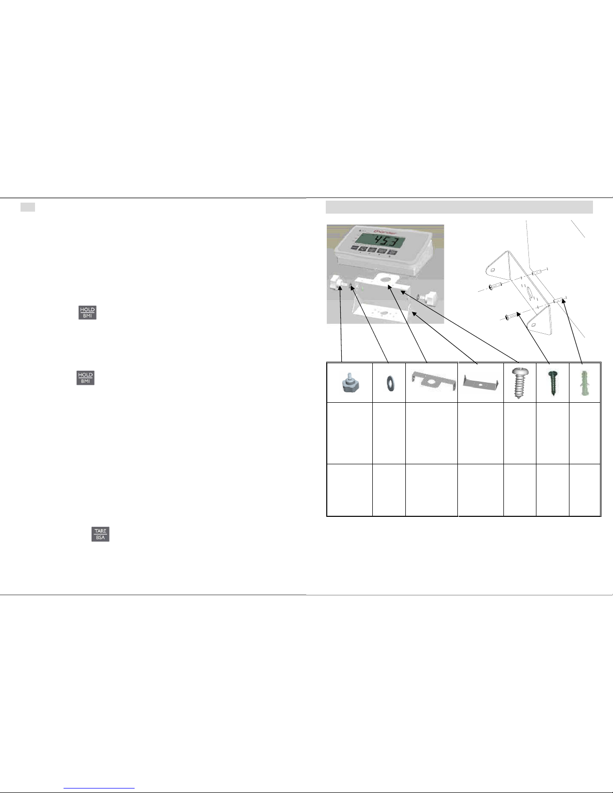
18
Note
Determination of average value is not possible when a person moves too much.
HOLD function won’t work if the weight is under 2 kg.
1. Switch on the scale. The diagnostic self-checks is performed. The
scale is ready for weighing when the „0.0 kg” displays on the
screen.
2. Place object/person on the scale.
3. Press key. When the triangle is flashing on the display,
the scale records the fluctuating weight values and then
calculates average weight and displays the result on the screen.
4. Remove object/person from the scale. The weight reading will
remain on the display.
5. Press key again to return the scale to the normal weighing
mode.
6. HOLD function can be activated before or after place the weight
on the SCALE.
4 Weighing with tare
Tare function allows the user to deduct the excess weight of a single tare object
value (additional loads or clothes) from the display reading, thus calculate the
actual net weight of the object/ person.
4.1.1 Taring
Place tare object (additional loads or clothes) on scale and
press to tare the weight of object.
The zero display and the symbol NET appear.
The tare weight remains stored until it is cleared.
27
ASSEMBLY OF BRACKET
Adjustable
feet
Spacer
Fixed plate
(top)
Fixed plate
(bottom)
Tapping
Screw
Screw
Plastic
anchor
2 2 1 1 2 2 2
Wall
Page 41
26
8. Printout Data Through USB cable connector
Click OK button to complete the setting. The PC will retrieve the
weighing & BMI data from the CHARDER scale and display on the
HyperTerminal program similar to the layout below.
While the Hyper Terminal program is running, type “P” KEY on the PC
keyboard to transmit a print command to printout from the thermal
printer on the CHARDER scale for hard copy of weighing data & BMI.
Or, press the [PRINT] button on the display panel of the CHARDER
scale, the printout presented below is the standard format print layout
as well as shown on the HyperTerminal computer screen.
GROSS WEIGHT 70.00kg
TARE WEIGHT 0.00kg
NET WEIGHT 0.00kg
USER HEIGHT 170.0cm
USER B.M.I. 24.2
01/01/2013 10:00
19
4.1.2 Clear the tare
Press to clear tare weight
The symbol NET disappear
The gross weight appears in the display.
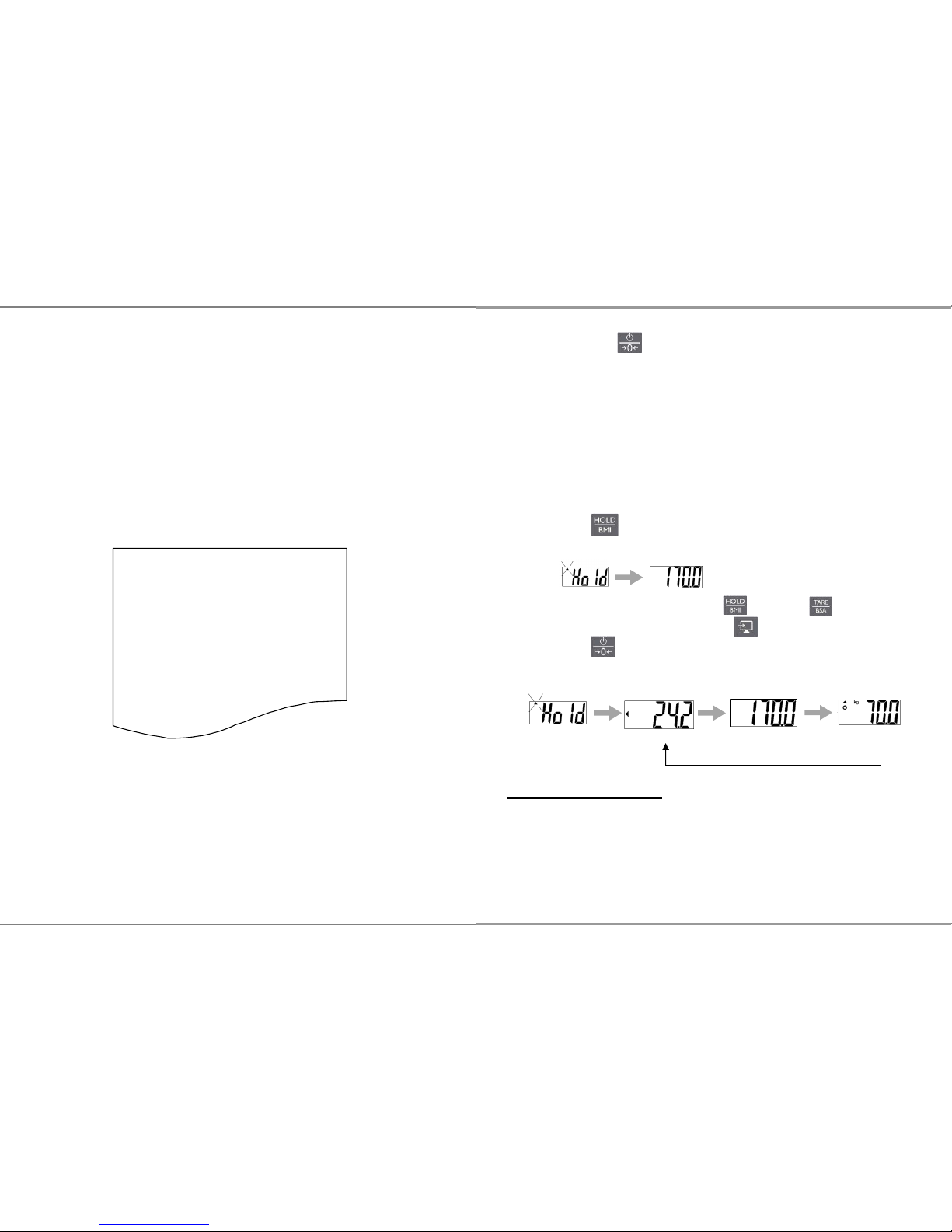
5 Weighing with BMI
For BMI calculation, height is needed, therefore it is recommended to measure the
height of subject before starting weighing procedure.
1. Switch on the scale.
2. Place object/person on the scale.
3. Press key and hold for 3 seconds. First, display will show
“HOLD” and lock weight then display show “height value”.
4. Adjust height value by using (↓) and (↑) keys.
5. Switch between digits by using (→) key.
6. Press to confirm height value.
7. Display will show “HOLD” and lock weight to calculate BMI.
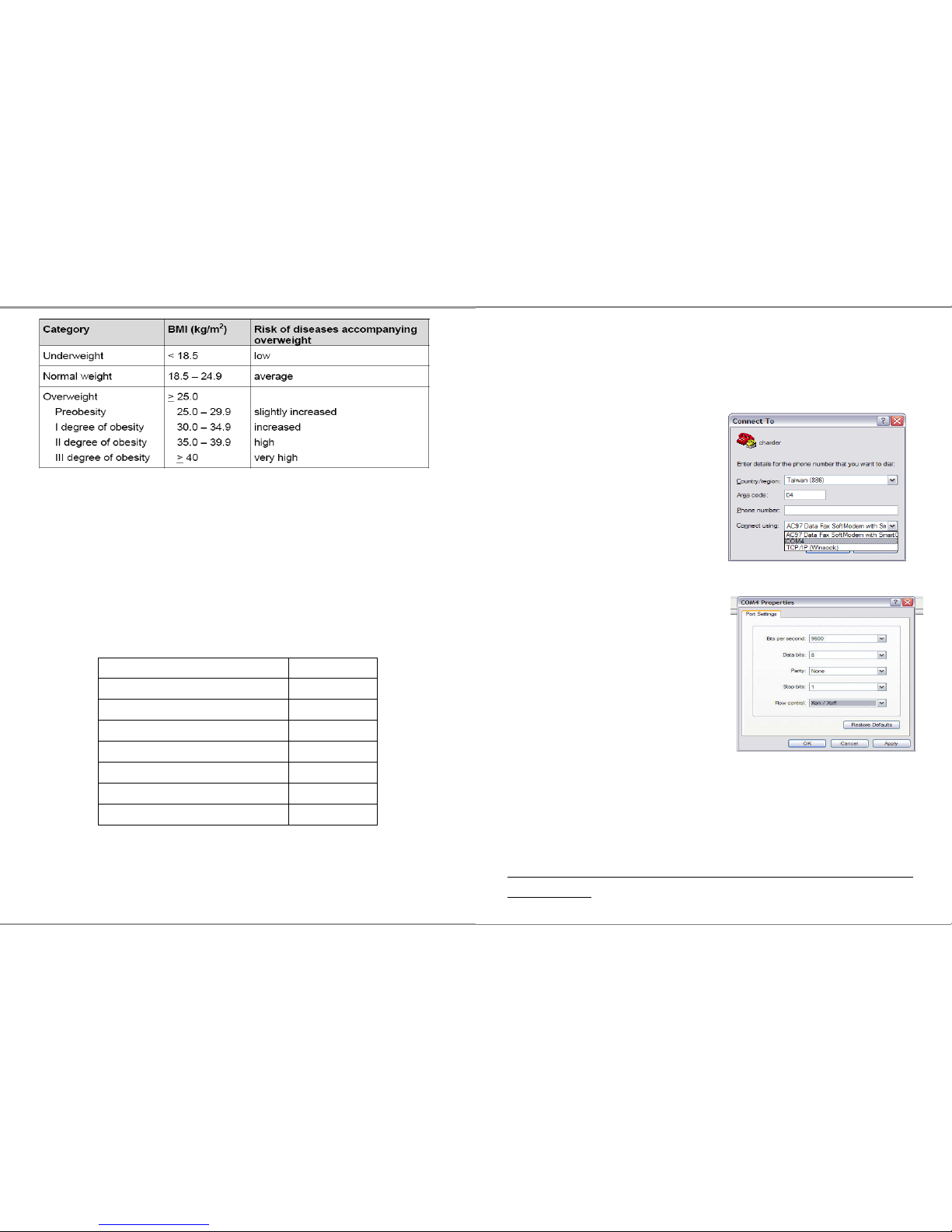
Body Mass Index Categories
Classification of weight for adults over 18 years on the basis of Body Mass Index
according to WHO, 2000 EK IV and WHO 2004 (WHO - World Health Organization).
BMI
Height
weight
Page 42
20
6 Weighing with BSA
- Values for Body surface area (BSA) is the measured or calculated surface area of a
human body. For many clinical purposes BSA is a better indicator of metabolic mass
than body weight because it is less affected by abnormal adipose mass. BSA are
commonly used in medicine, particularly to calculate doses of chemotherapeutic
agents and index cardiac output.
Average BSA for children of various ages, for men, and for women, are taken to
be:
Age BSA
Neonate (newborn) 0.25 m²
Child of 2 years 0.5 m²
9 years 1.07 m²
10 years 1.14 m²
12-13 years 1.33 m²
Women 1.6 m²
Men 1.9 m²
There was an average BSA of 1.73 m² for 3,000 cancer patients from 1990 to 1998 in a European
Organisation for Research and Treatment of Cancer (EORTC) database.
25
6. Select COM Port on User PC
Click Connect to select COM port on the computer. Then click OK.
7. Port Settings for Printout
Set up as below:
Baud rate: 9600 bps
Parity check: None
Data length: 8 bits
Stop bit: 1 bit
Handshake: RTS/CTS
Data code: ASCII
USB Driver Install
The scale confirms to the USB PL2303
Make sure the computer software has a USB scale interface.
PL2303 driver download:
http://www.prolific.com.tw/US/ShowProduct.aspx?pcid=41&showlevel=0
017-0037-0041
Page 43
24
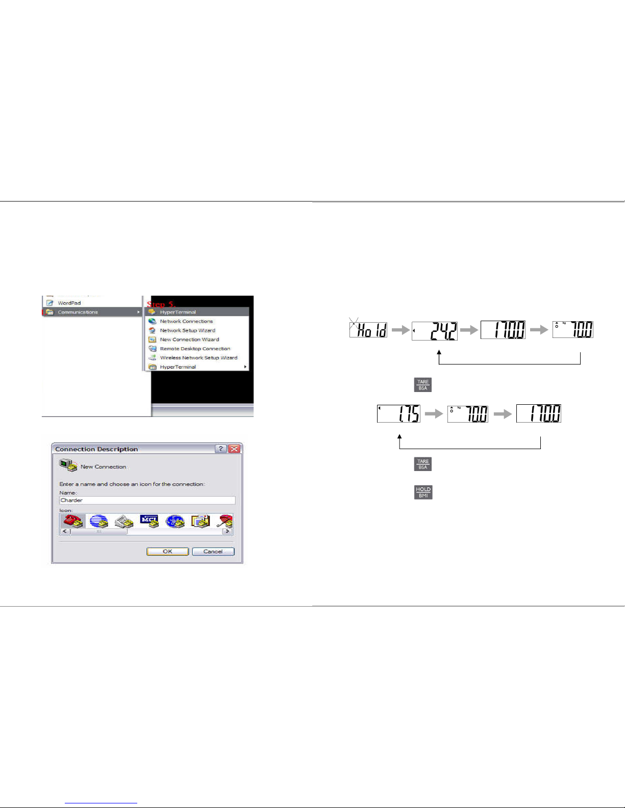
PC’s Windows OS with the following steps:
Step.1- Click on Start Button.
Step.2- Go to All Programs.
Step.3- Select Accessories.
Step.4- Find Communications.
Step.5- In Communications section click on HyperTerminal.
5. New Connection Description
Name the connection and click OK Button
21
During 2005 there was an average BSA of 1.79 m² for 3,613 adult cancer patients in the UK. Among
them the average BSA for men was 1.91 m² and for women was 1.71 m².
However, there is some evidence that BSA values are less accurate at extremes of height and weight,
where Body Mass Index may be a better estimate.
6.1.1 Enable BSA in BMI mode
1. Starting with BMI process
2. When BMI, weight and height is playing rotationally.
3. Press to play BSA value.
4. Press to return to BMI mode.
5. Press to return to normal mode.
BMI
Height
weight
Height
weight
BSA
Page 44
22
SETTING-UP MS3850
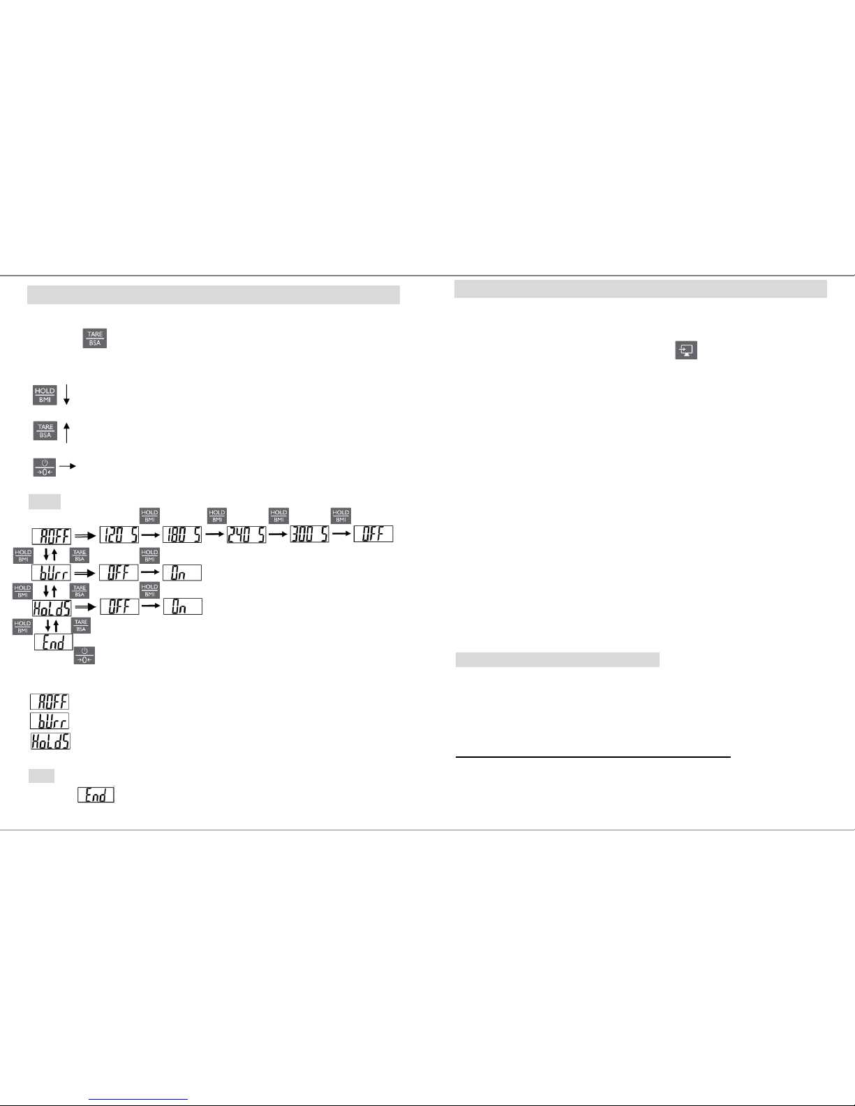
1. Switch on the scale.
2. Press key and hold for 6 seconds to enable setting mode.
3. LCD shows “SETUP” first and then “A.OFF” appears.
Switch between modes and menu
Reverse switch between modes and menu
Confirm setting.
MENU
AUTO-OFF TIME SETUP
This enables operator to select the auto turn OFF time of the device.
BUZZER ON/OFF SETUP
Set auto-off timer between 120/180/240/300/off
Set buzzer on and off
Set HOLD function release after unload weight ON and OFF.
Note
Confirm in the menu to save all settings.
23
PRINT function and data transmission
The Weighing, BMI and Height results can be keep in PC for records using USB interface
cable, which is connected to the USB plug at the back terminal.
After complete BMI and BSA process, simply press key to transfer the results to
PC.
HOW TO SETUP USB CONNECTIONS ON PC
1. Make sure the PC hardware device has USB port version2.0 or above
compatibility. Users may need to consult with local computer
accessories dealer to select the proper USB cable length that is most
suitable to work environment for best performance, then connect the
cable first between the PC and CHARDER Scale model.
2. Run HyperTerminal program under Windows OS computer and input
printer port parameter settings, please refer to the next Section in
<Step 7> on how to setup HyperTerminal program in user’s computer
for printer port parameters.
3. Once the HyperTerminal setting is ready, make sure the USB cable is
connected properly between the user PC’s USB port and the CHARDER
Scale Model again. Press PRINT button on the Scale Display Panel for
printout of weight & BMI data from thermal printer.
Hyper Terminal setting in PC for printout
Hyper Terminal is a freeware on PC Windows XP SP3 or lower to setup the
PC printer com-port with USB cable connector transmission.
For use on Windows Vista or higher please download hyper terminal
software program from Charder website:
http://www.chardermedical.com/download/dlist-4.htm
4. Start Hyper Terminal
After taking the weight and BMI, run Hyper Terminal program from the
 Loading...