

Page 1
SmartChef
®
Serial number | Número de serie
See rating Label on grill for serial number.
El número de serie se encuentra en la etiqueta de
especificaciones de la parrilla.
Date purchased | Fecha de compra
If you have questions or need assistance
during assembly, please call 1-800-241-8981.
Si tiene alguna pregunta o si Necesita
ayuda durante el Ensamblado, llámenos Al
1-800-241-8981.
463346017
3-Burner Gas Grill
10/21/16 • G466-001-110801
Page 2
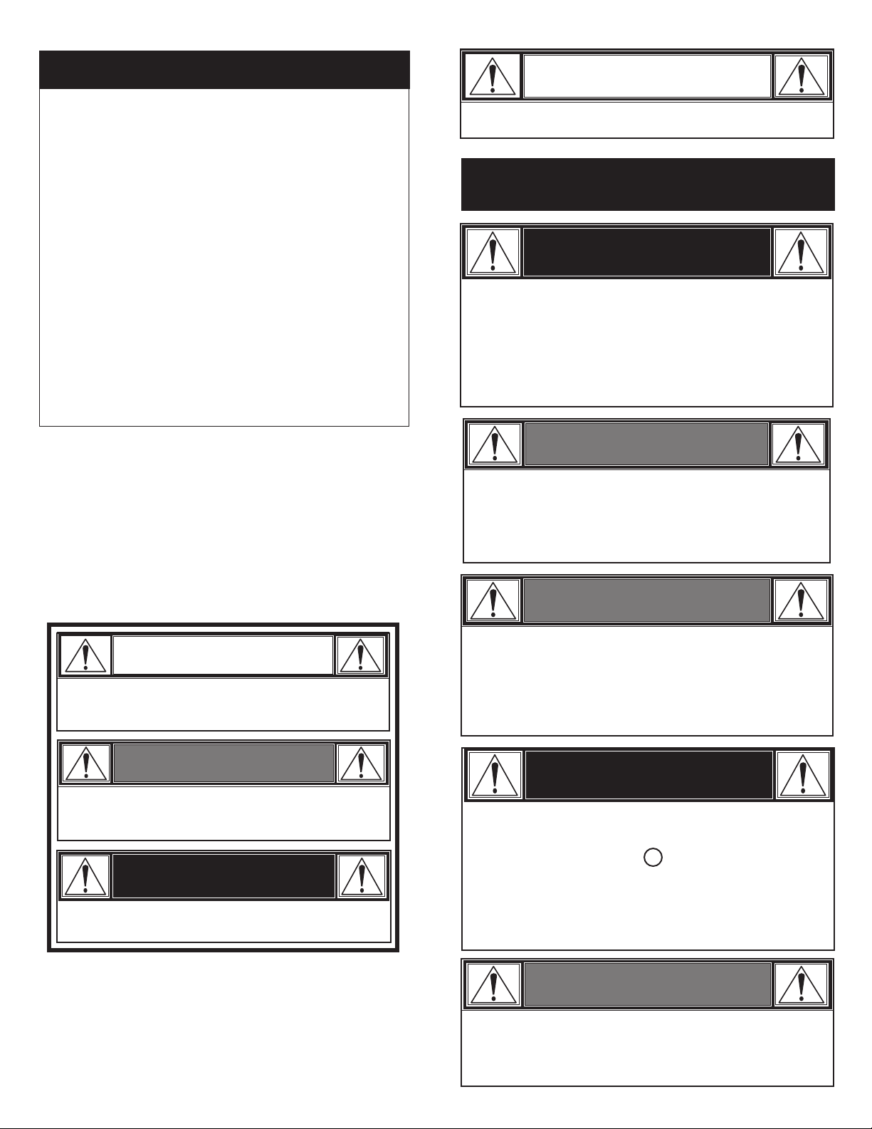
TABLE OF CONTENTS
CAUTION
For Your Safety . . . . . . . . . . . . . . . . . . . . . . . . . . . . . . . . . 2-4
Use and Care. . . . . . . . . . . . . . . . . . . . . . . . . . . . . . . . . . . 4-9
SmartChef Controls . . . . . . . . . . . . . . . . . . . . . . . . . . . . 10-12
Limited Warranty . . . . . . . . . . . . . . . . . . . . . . . . . . . . . . . . . 13
Assembly . . . . . . . . . . . . . . . . . . . . . . . . . . . . . . . . . . . . 26-52
Troubleshooting . . . . . . . . . . . . . . . . . . . . . . . . . . . . . . . 53-54
Parts Diagram . . . . . . . . . . . . . . . . . . . . . . . . . . . . . . . . . . . 58
Parts List . . . . . . . . . . . . . . . . . . . . . . . . . . . . . . . . . . . . . . . 59
Hardware List. . . . . . . . . . . . . . . . . . . . . . . . . . . . . . . . . 61-62
Registration Card. . . . . . . . . . . . . . . . . . . . . . . . . . . . . . . . . 63
INSTALLER/ASSEMBLER:
Leave this manual with consumer.
CONSUMER:
Keep this manual for future reference.
SAFETY SYMBOLS
The symbols and boxes shown below explain what each
heading means. Read and follow all of the messages found
throughout the manual.
For residential use only. Do not use for commercial cooking.
THIS GRILL IS FOR OUTDOOR USE
ONLY.
DANGER
If you smell gas:
1. Shut off gas to the appliance
2. Extinguish any open flame.
3. Open lid.
4. If odor continues, keep away from the appliance and
immediately call your gas supplier or your fire
department.
WARNING
1. Do not store or use gasoline or other flammable
liquids or vapors in the vicinity of this or any other
appliance.
2. An LP cylinder not connected for use shall not be
stored in the vicinity of this or any other appliance.
WARNING
CAUTION
CAUTION: Indicates a potentially hazardous situation or
unsafe practice which, if not avoided, may result in minor
or moderate injury.
WARNING
WARNING: Indicates a potentially hazardous situation
which, if not avoided, could result in death or serious
injury.
DANGER
DANGER: Indicates an imminently hazardous situation
which, if not avoided, will result in death or serious injury.
Tools needed for assembly:
Adjustable wrench (not provided)
Screwdriver (not provided)
7/16" Combination wrench (not provided)
3/4" Combination wrench (not provided)
Do not attempt to repair or alter the
hose/valve/regulator for any “assumed” defect. Any
modification to this assembly will void your
warranty and create the risk of a gas leak and fire.
Use only authorized replacement parts supplied by
manufacturer.
DANGER
If during operation the flames go out (You smell gas or
cannot see the flame)
1. Turn the burner controls OFF
2. Open lid.
3. Wait 5 minutes and repeat the lighting procedure.
If the burner goes out, gas will continue to flow out of the
burner and could accidently ignite with risk of injury.
WARNING
Do not cover grates with aluminum foil or any other
material. This will block burner ventilation and
create a potentially dangerous condition resulting in
property damage and/or personal injury.
2
Page 3
WARNING
CAUTION
Failure to follow all manufacturer’s instructions could result in
serious personal injury and/or property damage.
CAUTION
Read and follow all safety statements, assembly
instructions, and use and care directions before attempting
to assemble and cook.
CAUTION
Some parts may contain sharp edges. Wear protective
gloves if necessary.
CAUTION
Grease Fires
• Putting out grease fires by closing the lid is not possible.
Grills are well ventilated for safety reasons.
• Do not use water on a grease fire. Personal injury may
result. If a grease fire develops, turn knobs and LP
tank off.
• If grill has not been regularly cleaned, a grease fire can
occur that may damage the product. Pay close attention
while preheating or burning off food residue to insure
that a grease fire does not develop.
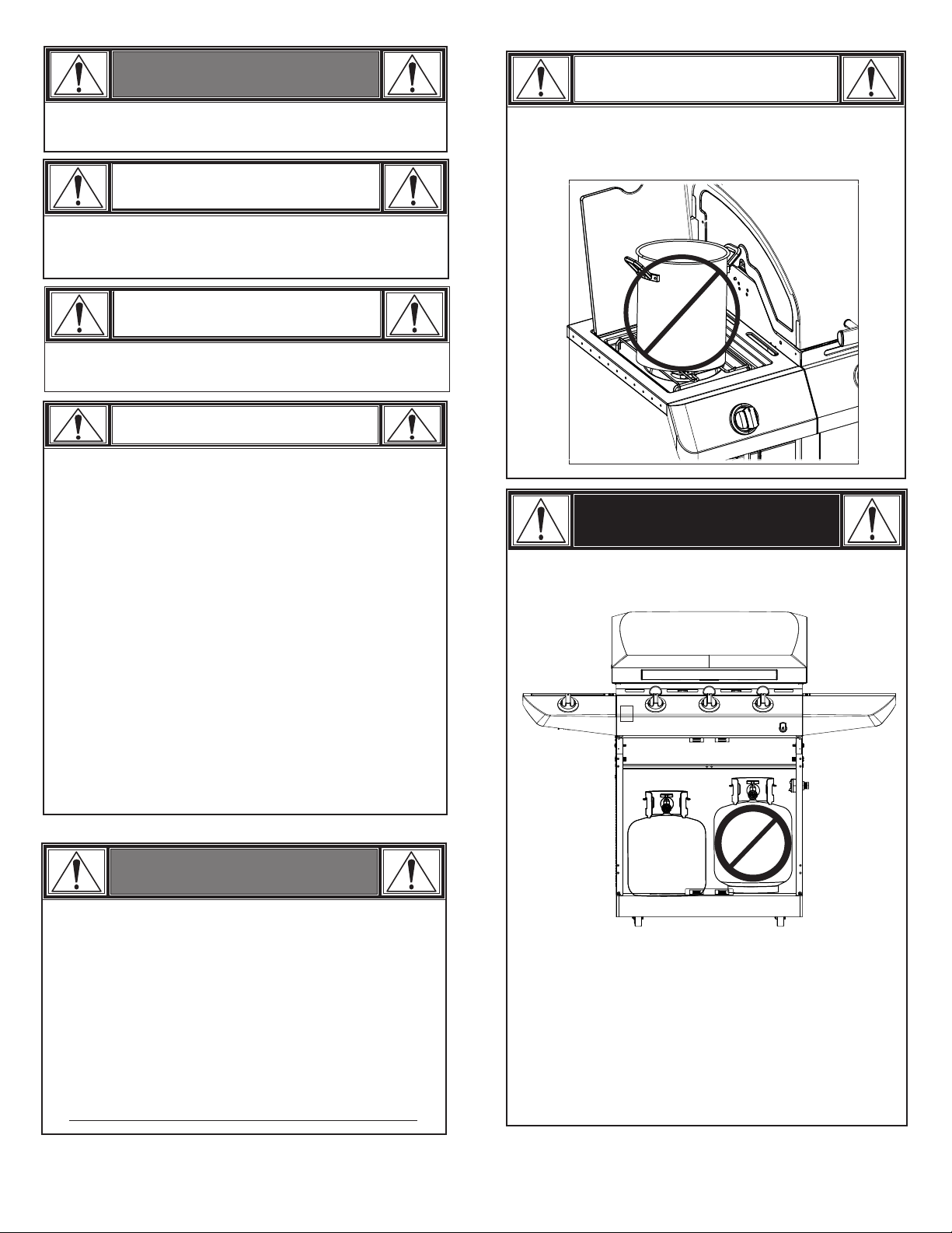
Using pots larger than 6 quarts in capacity could exceed
weight limit of the side burner shelf or side shelf, resulting
in failure of grill cart components.
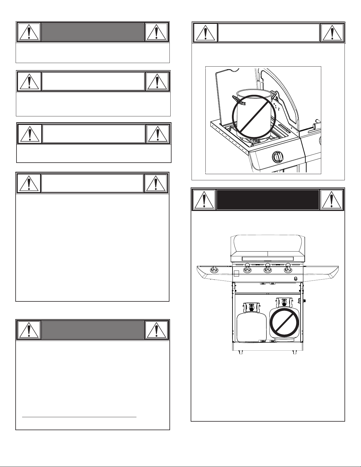
DANGER
•
NEVER store a spare LP cylinder under or near the
appliance or in an enclosed area.
• The best way to prevent grease fires is regular cleaning of
the grill following instructions on General Grill Cleaning
and Cleaning The Burner Assembly.
WARNING
CALIFORNIA PROPOSITION 65
1. Combustible by-products produced when using this
product contains chemicals known to the State of
California to cause cancer, birth defects, or other
reproductive harm.
2. This product contains chemicals, including lead and
lead compounds, known to the State of California to
cause cancer, birth defects or other reproductive harm.
Wash your hands after handling this product.
Never fill a cylinder beyond 80% full.
•
An over filled or improperly stored cylinder is a hazard
•
due to possible gas release from the safety relief valve.
This could cause an intense fire with risk of property
damage, serious injury or death.
•
If you see, smell or hear gas escaping, immediately get
away from the LP cylinder/appliance and call your fire
department.
3
Page 4
Installation Safety Precautions
•Use grill, as purchased, only with LP (propane) gas and the
regulator/valve assembly supplied.
•Grill installation must conform with local codes, or in their
absence of local codes, with either the National Fuel Gas
Code, ANSI Z223.1/ NFPA 54, Natural Gas and Propane
Installation Code, CSA B149.1, or Propane Storage and
Handling Code, B149.2.
•All electrical accessories (such as rotisserie) must be
electrically grounded in accordance with local codes, or
National Electrical Code, ANSI / NFPA 70 or Canadian
Electrical Code, CSA C22.1. Keep any electrical cords
and/or fuel supply hoses away from any hot surfaces.
•This grill is safety certified for use in the United States
and/or Canada only. Do not modify for use in any other
location. Modification will result in a safety hazard.
USE AND CARE
LP Cylinder Removal, Transport and Storage
•Turn OFF all control knobs and LP cylinder valve. Turn coupling
nut counterclockwise by hand only - do not use tools to
disconnect. Loosen cylinder screw beneath bottom shelf or
disconnect other retention means, then lift LP cylinder up and
and out of cart. Install safety cap onto LP cylinder valve.
Always use cap and strap supplied with valve. Failure to use
safety cap as directed may result in serious personal
injury and/or property damage.
•A disconnected LP cylinder in storage or being transported
must have a safety cap installed (as shown). Do not store an
LP cylinder in enclosed spaces such as a carport, garage,
porch, covered patio or other building. Never leave an LP
cylinder inside a vehicle which may become overheated by the
sun.
•Do not store an LP cylinder in an area where children play.
LP Cylinder
•The LP cylinder used with your grill must meet the
following requirements:
•Use LP cylinders only with these required measurements: 12"
(30.5cm) (diameter) x 18" (45.7 cm) (tall) with 20 lb. (9 kg.)
capacity maximum.
•LP cylinders must be constructed and marked in accordance
with specifications for LP cylinders of the U.S. Department of
Transportation (DOT) or for Canada, CAN/CSA-B339, cylinders,
spheres and tubes for transportation of dangerous goods,
Transport Canada (TC). See LP cylinder collar for marking.
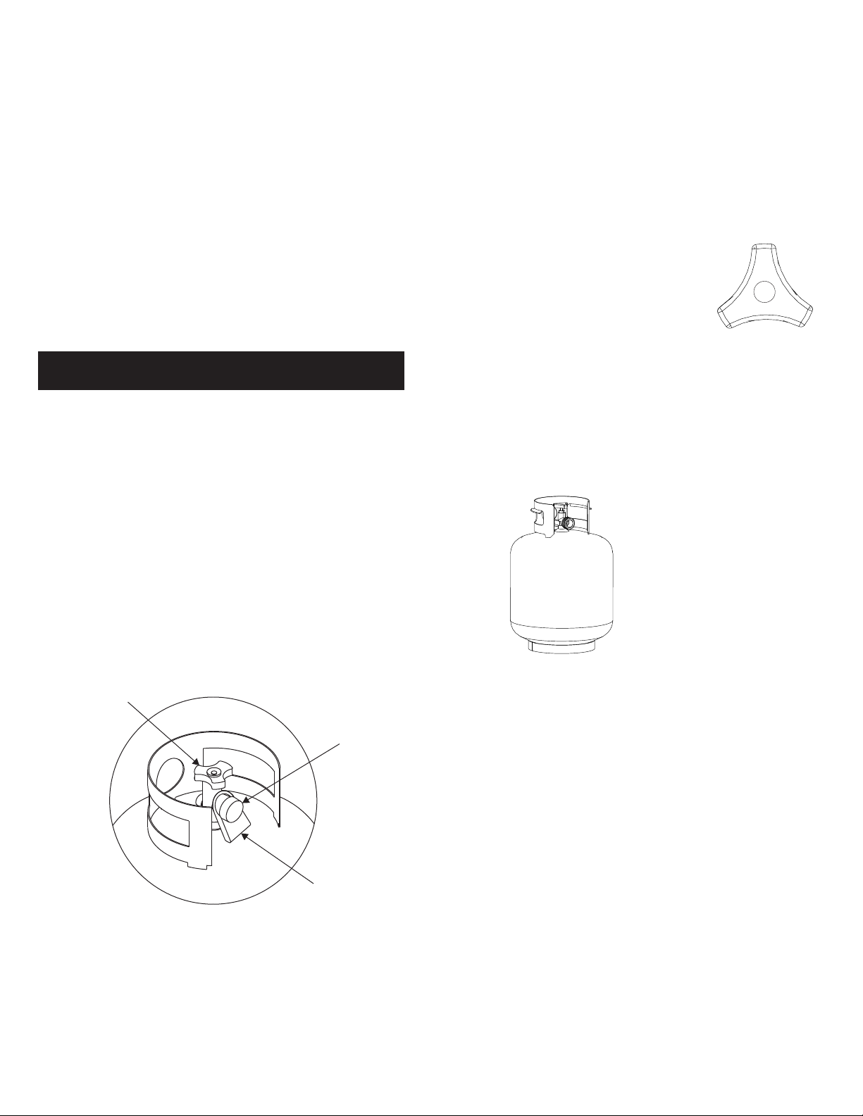
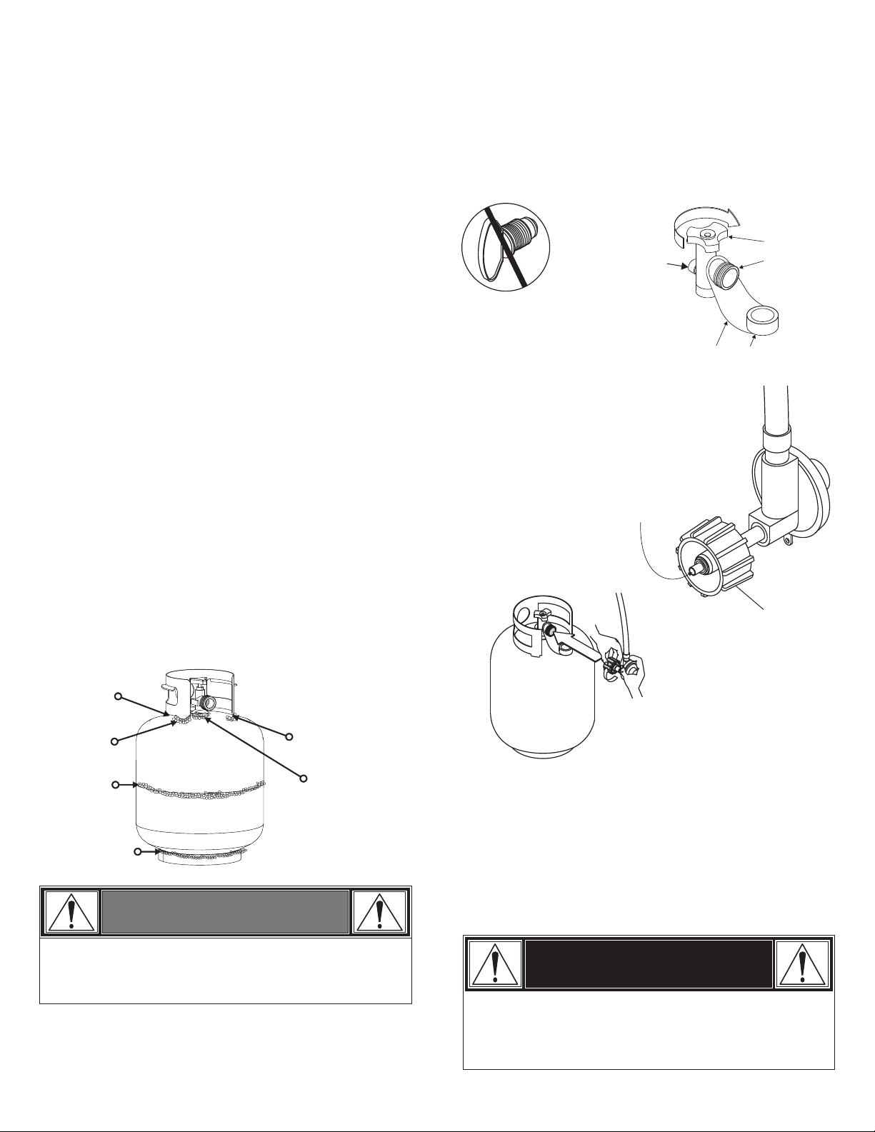
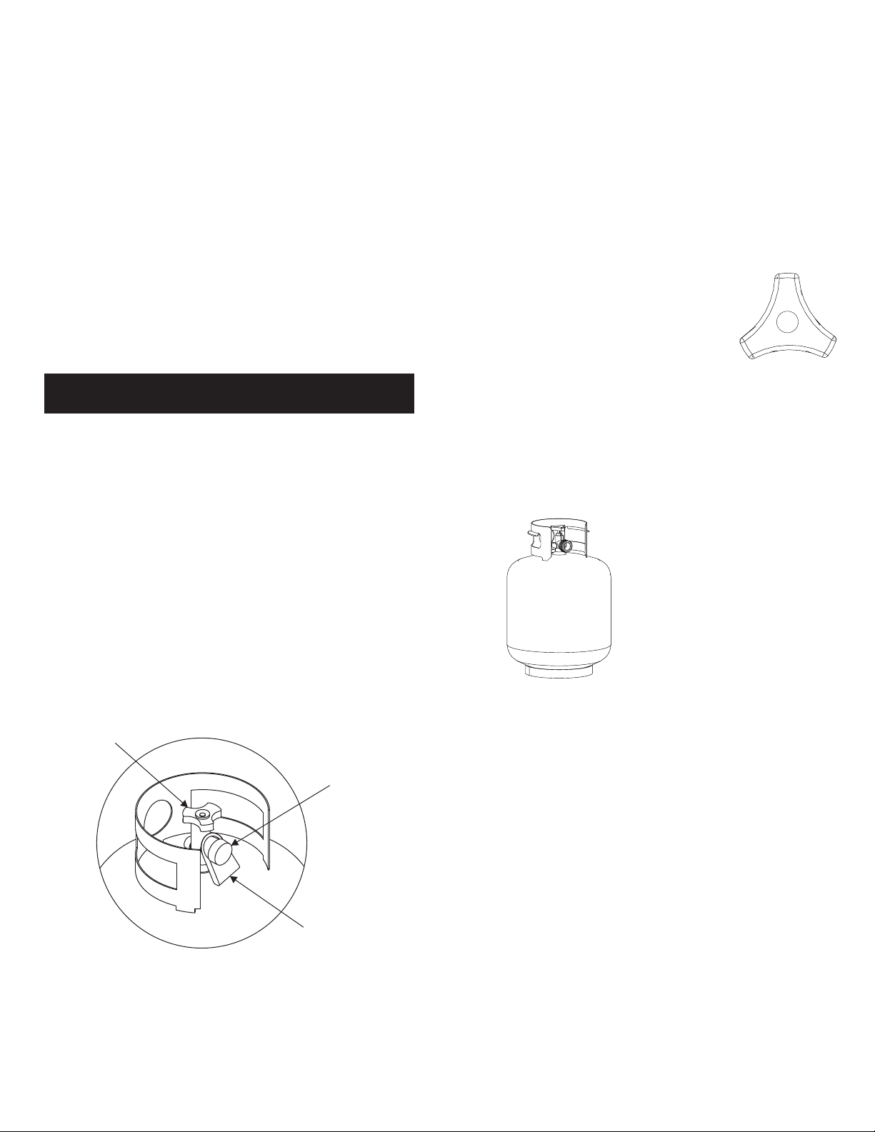
•LP cylinder valve must have:
•Type 1 outlet compatible with
regulator or grill.
•Safety relief valve.
•UL listed Overfill Protection Device (OPD). This
OPD safety feature is identified by a unique
triangular hand wheel. Use only LP cylinders
equipped with this type of valve.
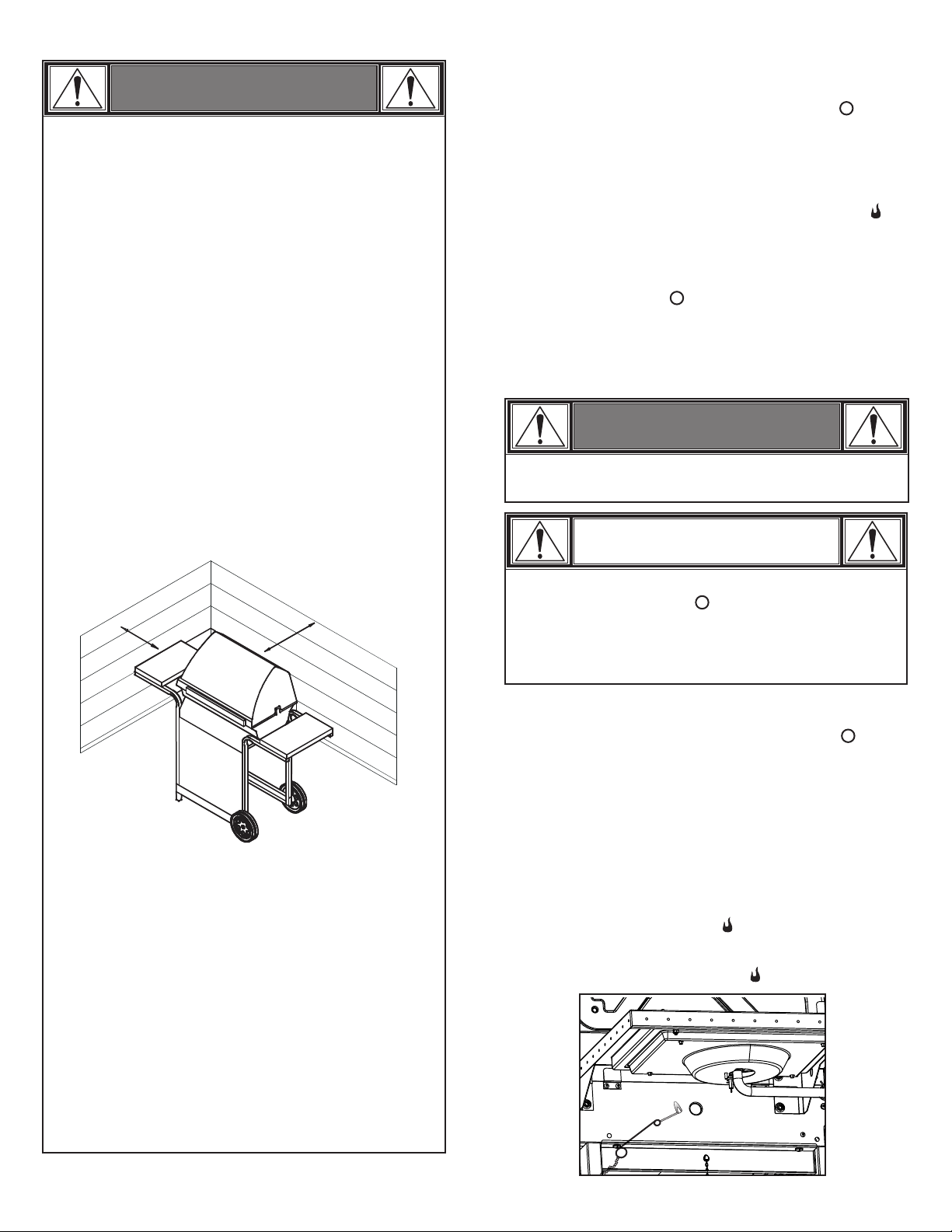
•LP cylinder must be upright for vapor withdrawal and include
collar to protect LP cylinder valve. Always keep LP cylinders in
upright position during use, transit or storage.
LP cylinder in upright position
for vapor withdrawal
OPD Hand
Wheel
LP Cylinder Valve
Safety Cap
Retainer Strap
LP (Liquefied Petroleum Gas)
•LP gas is nontoxic, odorless and colorless when produced. For
Your Safety, LP gas has been given an odor (similar to rotten
cabbage) so that it can be smelled.
•LP gas is highly flammable and may ignite unexpectedly when
mixed with air.
LP Cylinder Filling
•Use only licensed and experienced dealers.
•LP dealer must purge new cylinder before filling.
•Dealer should NEVER fill LP cylinder more than 80% of LP
cylinder volume. Volume of propane in cylinder will vary by
temperature.
•A frosty regulator indicates gas overfill. Immediately close
LP cylinder valve and call local LP gas dealer for assistance.
•Do not release liquid propane (LP) gas into the atmosphere.
This is a hazardous practice.
•To remove gas from LP cylinder, contact an LP dealer or call a
local fire department for assistance. Check the telephone
directory under “Gas Companies” for nearest certified LP
dealers.
4
Page 5
LP Cylinder Exchange
• Many retailers that sell grills offer you the option of replacing
your empty LP cylinder through an exchange service. Use only
those reputable exchange companies that inspect, precision
fill, test and certify their cylinders. Exchange your cylinder
only for an OPD safety feature-equipped cylinder as
described in the "LP Cylinder" section of this manual.
• Always keep new and exchanged LP cylinders in upright
position during use, transit or storage.
• Leak test new and exchanged LP cylinders BEFORE
connecting to grill.
• Place safety cap on cylinder valve outlet whenever the cylinder
is not in use. Only install the type of safety cap on the cylinder
valve outlet that is provided with the cylinder valve. Other types
of caps or plugs may result in leakage of propane.
LP Cylinder Leak Test
For your safety
• Leak test must be repeated each time LP cylinder is
exchanged or refilled.
• Do not smoke during leak test.
• Do not use an open flame to check for gas leaks.
Connecting Regulator to the LP Cylinder
1.LP cylinder must be properly secured onto grill. (Refer to
assembly section.)
2.Turn all control knobs to the OFF position.
3.Turn LP cylinder OFF by turning hand-wheel clockwise to a full
stop.
4.Remove the safety cap from LP cylinder valve. Always use cap
and strap if supplied with valve.
c
k
w
o
i
l
s
C
e
f
f
O
Safety Relief
Valve
Do not use a POL transport
plug (plastic part with external
threads)! It will defeat the
safety feature of the valve.
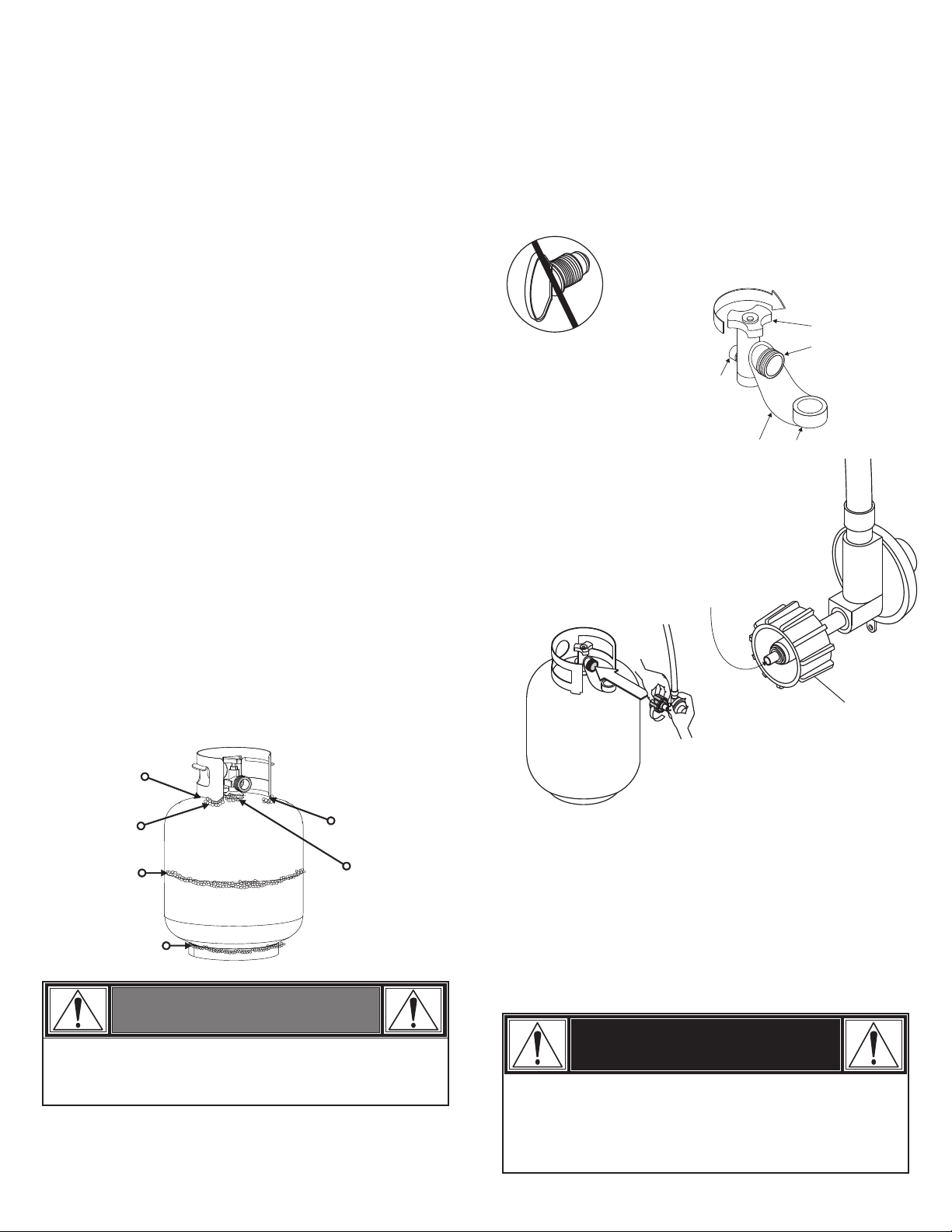
5.Hold regulator and insert nipple into LP
cylinder valve. Hand-tighten the coupling
nut, holding regulator in a straight line with
LP cylinder valve so as not to cross-thread
the connection.
Strap and Cap
OPD Hand
Wheel
Type 1 outlet
with thread
on outside
• Grill must be leak tested outdoors in a well-ventilated area,
away from ignition sources such as gas fired or electrical
appliances. During leak test, keep grill away from open flames
or sparks.
• Use a clean paintbrush and a 50/50 mild soap and water
solution. Brush soapy solution onto areas indicated by arrows
in figure below.
• Do not use household cleaning agents. Damage to gas
train components can result.
WARNING
Nipple has to be
centered into the LP
cylinder valve.
Straig
ht
Hold coupling nut and regulator
as shown for proper connection
to LP cylinder valve.
Coupling nut
6.Turn the coupling nut clockwise and tighten to a full stop. The
regulator will seal on the back-check feature in the LP cylinder
valve, resulting in some resistance. An additional one-half to
three-quarters turn is required to complete the
connection. Tighten by hand only – do not use tools.
NOTE:
If you cannot complete the connection, disconnect regulator
and repeat steps 5 and 6. If you are still unable to complete the
connection, do not use this regulator!
If “growing” bubbles appear, do not use or move the LP
cylinder. Contact an LP gas supplier or your fire department!
DANGER
• Do not insert any tool or foreign object into the valve outlet or
safety relief valve. You may damage the valve and cause a
leak. Leaking propane may result in explosion, fire, severe
personal injury, or death.
5
Page 6
WARNING
WARNING
• Do not use grill until leak-tested.
• If a leak is detected at any time, STOP! Turn off
gas at source and correct leak.
• If you cannot stop a gas leak by closing the LP cylinder valve
leave area and call your fire department!
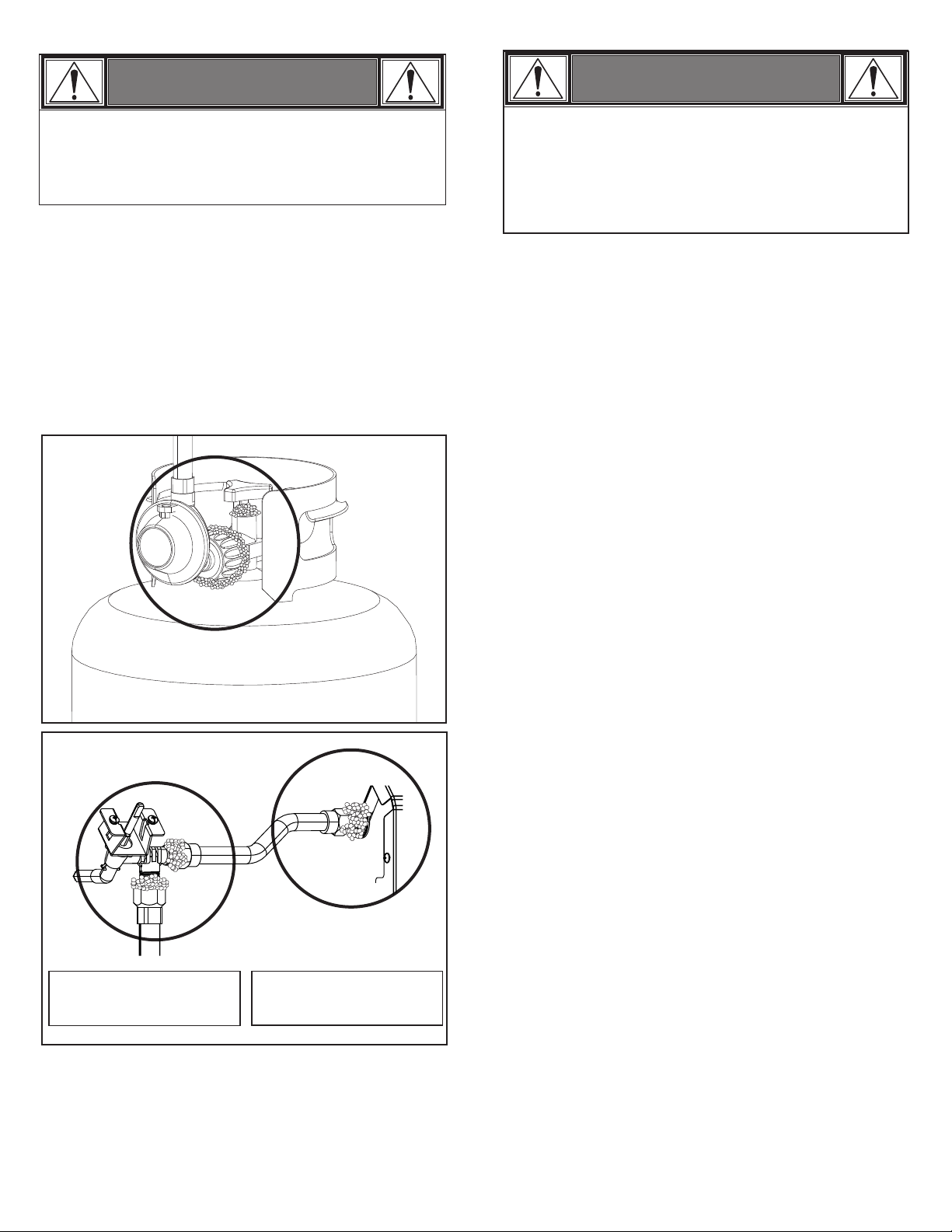
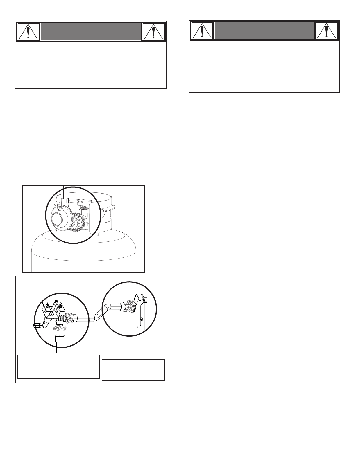
Leak Testing Valves, Hose and Regulator
1. Turn all grill control knobs to OFF.
2. Be sure regulator is tightly connected to LP cylinder.
3. Plug in power cord and turn on Control Panel.
4. Completely open LP cylinder valve by turning hand wheel
counterclockwise. If you hear a rushing sound, turn gas off
immediately. There is a major leak at the connection. Correct
before proceeding.
5. Brush soapy solution onto areas circled below, or other similar
fittings on your grill.
• Outdoor gas appliance is not intended to be installed in or
on a boat.
• Outdoor gas appliance is not intended to be installed in or on
an RV.
• Never attempt to attach this grill to the self-contained LP
gas system of a camper trailer or motor home.
Safety Tips
• Before opening LP cylinder valve, check the coupling nut for
tightness.
• When grill is not in use, turn off all control knobs, LP cylinder
valve and unplug power cord.
• Never move grill while in operation or still hot.
• Some surfaces will be hot during use. Use long-handled
barbecue utensils and oven mitts to avoid burns and splatters.
• Maximum load for sideburner and side shelf is 10 lbs.
• The grease tray or cup must be installed during use and
emptied after each use. Do not remove grease tray or cup
until grill has completely cooled.
• Clean grill often, preferably after each cookout. If a bristle
brush is used to clean any of the grill cooking surfaces, ensure
no loose bristles remain on cooking surfaces prior to grilling. It
is not recommended to clean cooking surfaces while grill is hot.
• If you notice grease or other hot material dripping from grill
onto valve, hose or regulator, turn off gas supply at once.
Determine the cause, correct it, then clean and inspect valve,
hose and regulator before continuing. Perform a leak test.
NOTE: Sideburner shelf
fascia and other parts not
shown for clarity.
6. If “growing” bubbles appear, there is a leak. Close LP cylinder
valve immediately and retighten connections. If leaks cannot
be stopped do not try to repair. Call for replacement parts.
7. Always close LP cylinder valve after performing leak test by
turning hand wheel clockwise.
NOTE: Your grill may NOT
be equipped with a
sideburner.
• Keep ventilation openings in cylinder enclosure (grill cart) free
and clear of debris.
• Do not store objects or materials inside the grill cart enclosure
that would block the flow of combustion air to the underside of
either the control panel or the firebox bowl.
• The regulator may make a humming or whistling noise during
operation. This will not affect safety or use of grill.
• If you have a grill problem see the "Troubleshooting” Section or
visit charbroil.com/smartchefgrill.
• If the regulator frosts, turn off grill and LP cylinder valve
immediately. This indicates a problem with the cylinder and it
should not be used on any product. Return to supplier!
6
Page 7
WARNING
For Safe Use of Your Grill and to Avoid Serious Injury:
• Do not let children operate or play near grill.
• Keep grill area clear and free from materials that burn.
• Do not block holes in sides or back of grill.
• Check burner flames regularly.
• Use grill only in well-ventilated space. NEVER use in
enclosed space such as carport, garage, porch, covered
patio, or under an overhead structure of any kind.
• Do not use charcoal or ceramic briquets in a gas grill.
• Do not cover grates with aluminum foil or any other
material. This will block burner ventilation and create a
potentially dangerous condition resulting in property
damage and/or personal injury.
• Use grill at least 3 ft. from any wall or surface. Maintain
10 ft. clearance to objects that can catch fire or sources of
ignition such as pilot lights on water heaters, live electrical
appliances, etc.
Ignitor Lighting
• Do not lean over grill while lighting.
1. Turn gas burner control valves to (OFF).
2. Plug in power cord. Press power button to turn ON Control
Panel.
3. Open lid during lighting or re-lighting.
4. Turn ON gas at LP cylinder.
5. To ignite, push and turn burner knob to HIGH. Immediately,
push and hold ELECTRONIC IGNITION button until the burner
lights.
6. If ignition does NOT occur in 5 seconds, turn the burner
controls OFF , wait 5 minutes and repeat the lighting
procedure. If ignitor does not work, follow match lighting
instructions in manual.
7. Repeat steps 4 and 5 to light other main burners.
WARNING
Turn controls and gas source or tank OFF when not
in use.
3 ft.
• NEVER attempt to light or re-light burner with lid
closed. A buildup of non-ignited gas inside a closed
grill is hazardous.
• Never operate grill with LP cylinder out of correct
position specified in assembly instructions.
• Always close LP cylinder valve and remove coupling nut
before moving LP cylinder from specified operation
position.
• Apartment Dwellers:
Check with management to learn the requirements and fire
codes for using an LP gas grill in your apartment complex.
If allowed, use outside on the ground floor with a three (3)
foot clearance from walls or rails. Do not use on or under
balconies.
3 ft.
CAUTION
If ignition does NOT occur in 5 seconds, turn the burner
controls OFF, wait 5 minutes and repeat the lighting
procedure. If the burner does not ignite with the valve
open, gas will continue to flow out of the burner and
could accidently ignite with risk of injury.
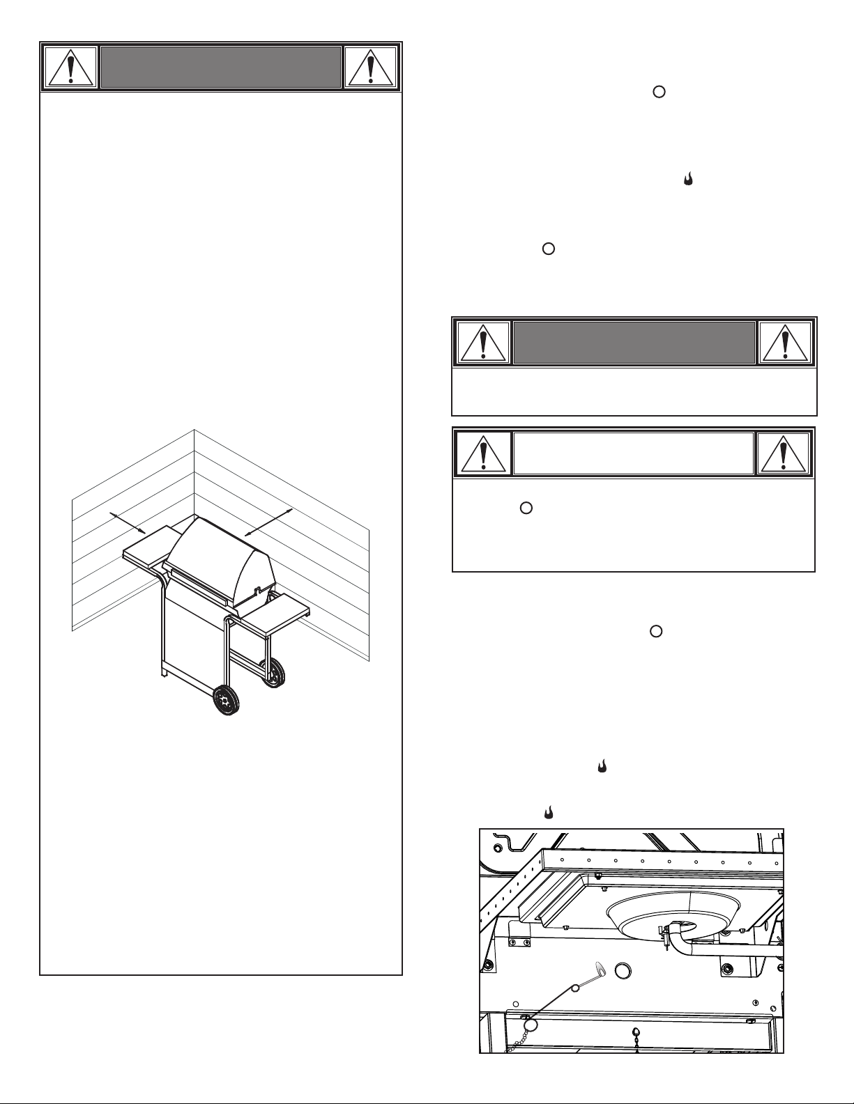
Match-Lighting
• Do not lean over grill while lighting.
1. Turn gas burner control valves to (OFF).
2. Plug in power cord. Press power button to turn ON Control
Panel.
3. Open lid during lighting or re-lighting.
4. Turn ON gas at LP cylinder.
5. Place match into match holder (hanging from side panel of
grill). Light match; then light burner by placing match through
the match light hole on side of grill. Immediately push in and
turn burner knob to the HIGH position. Be sure burner lights
and stays lit.
6. Light adjacent burners in sequence by pushing knobs in and
turning to the HIGH position.
7
Page 8
Side Burner lighting instructions
• Do not lean over grill while lighting.
1. Turn gas burner control valves to (OFF).
2. Open lid during lighting or re-lighting.
3. Turn ON gas at LP cylinder.
4. To ignite, push and turn burner knob to HIGH. Immediately,
push and hold ELECTRONIC IGNITION button until the burner
lights.
5. If ignition does NOT occur in 5 seconds, turn the burner controls
OFF , wait 5 minutes and repeat the lighting procedure. If
ignitor does not work, follow match lighting instructions in
manual.
Sideburner Match Lighting
• Do not lean over grill while lighting.
1. Turn gas burner control valves to (OFF).
2. Open lid during lighting or re-lighting.
3. Turn ON gas at LP cylinder.
4. Place lit match near burner. Immediately turn sideburner
knob to the HIGH position. Be sure burner lights and stays
lit.
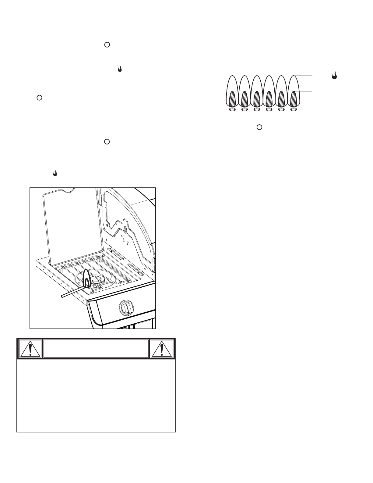
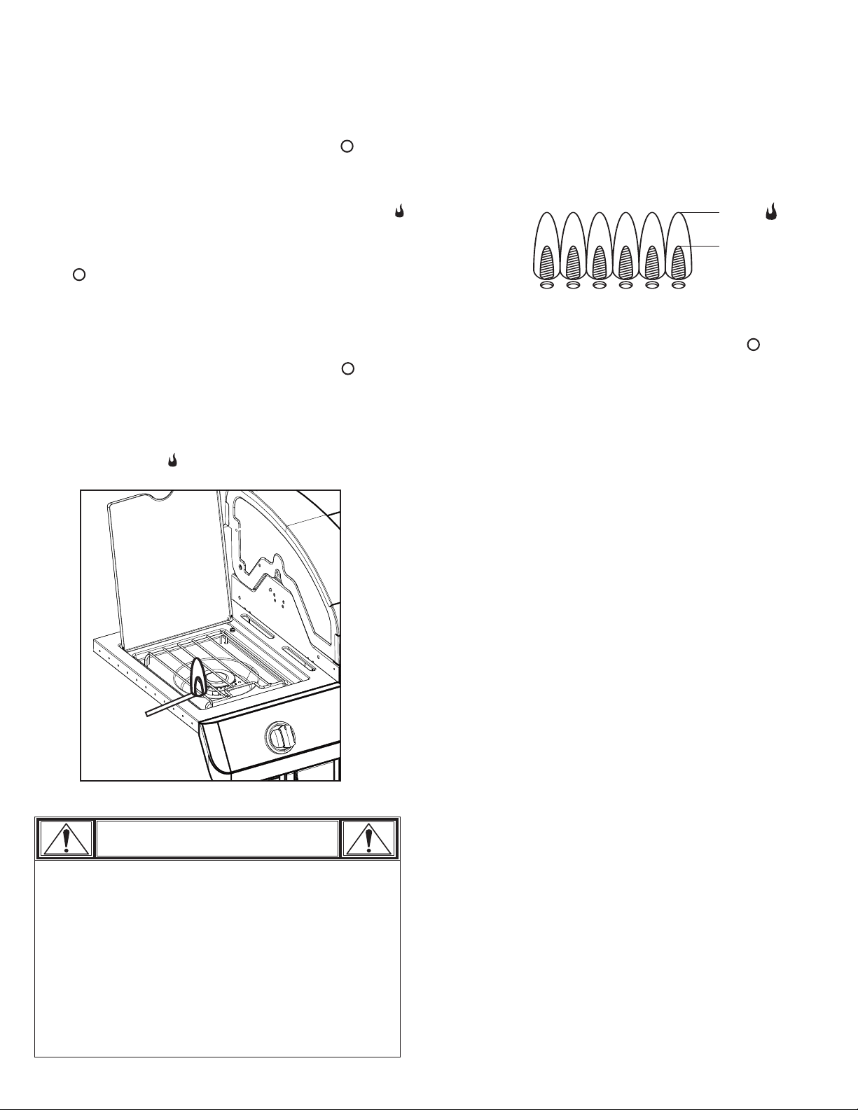
Burner Flame Check
• Remove cooking grates and heat tents. Light burners, rotate
knobs from HIGH to LOW. You should see a smaller flame in
LOW position than seen on HIGH. Perform burner flame check
on side burner, also. Always check flame prior to each use. If
only low flame is seen refer to "Sudden drop or low flame" in
the Troubleshooting Section.
HIGH
LOW
Turning Grill Off
• Turn all knobs to the OFF position. Turn LP cylinder off by
turning hand-wheel clockwise to a full stop. Unplug power
cord.
Ignitor Check
• Turn gas off at LP cylinder. Press and hold electronic ignitor
button. "Click" should be heard and spark seen each time in
each collector box or between burner and electrode. See
"Troubleshooting" if no click or spark.
Valve Check
• Important: Make sure gas is off at LP cylinder before
checking valves. Knobs lock in OFF position. To check valves,
first push in knobs and release, knobs should spring back. If
knobs do not spring back, replace valve assembly before using
grill. Turn knobs to LOW position then turn back to OFF position.
Valves should turn smoothly.
CAUTION
• Putting out grease fires by closing the lid is not possible.
Grills are well ventilated for safety reasons.
• Do not use water on a grease fire. Personal injury may
result. If a grease fire develops, turn knobs and LP
cylinder off.
• Do not leave grill unattended while preheating or burning
off food residue on HI. If grill has not been regularly
cleaned, a grease fire can occur that may damage the
product.
Hose Check
• Before each use, check to see if hoses are cut or worn or
kinked. Replace damaged hoses before using grill. Use only
valve/hose/regulator specified by manufacturer.
Storing Your Grill
• Clean cooking grates.
• Store in dry location.
• When LP cylinder is connected to grill, store outdoors in a
well-ventilated space and out of reach of children.
• Cover grill if stored outdoors. Choose from a variety of grill
covers offered by Char-Broil at charbroil.com.
• Store grill indoors ONLY if LP cylinder is turned off and
disconnected, removed from grill and stored outdoors.
• When removing grill from storage, follow “Cleaning the
Burner Assembly” instructions before starting grill.
8
Page 9
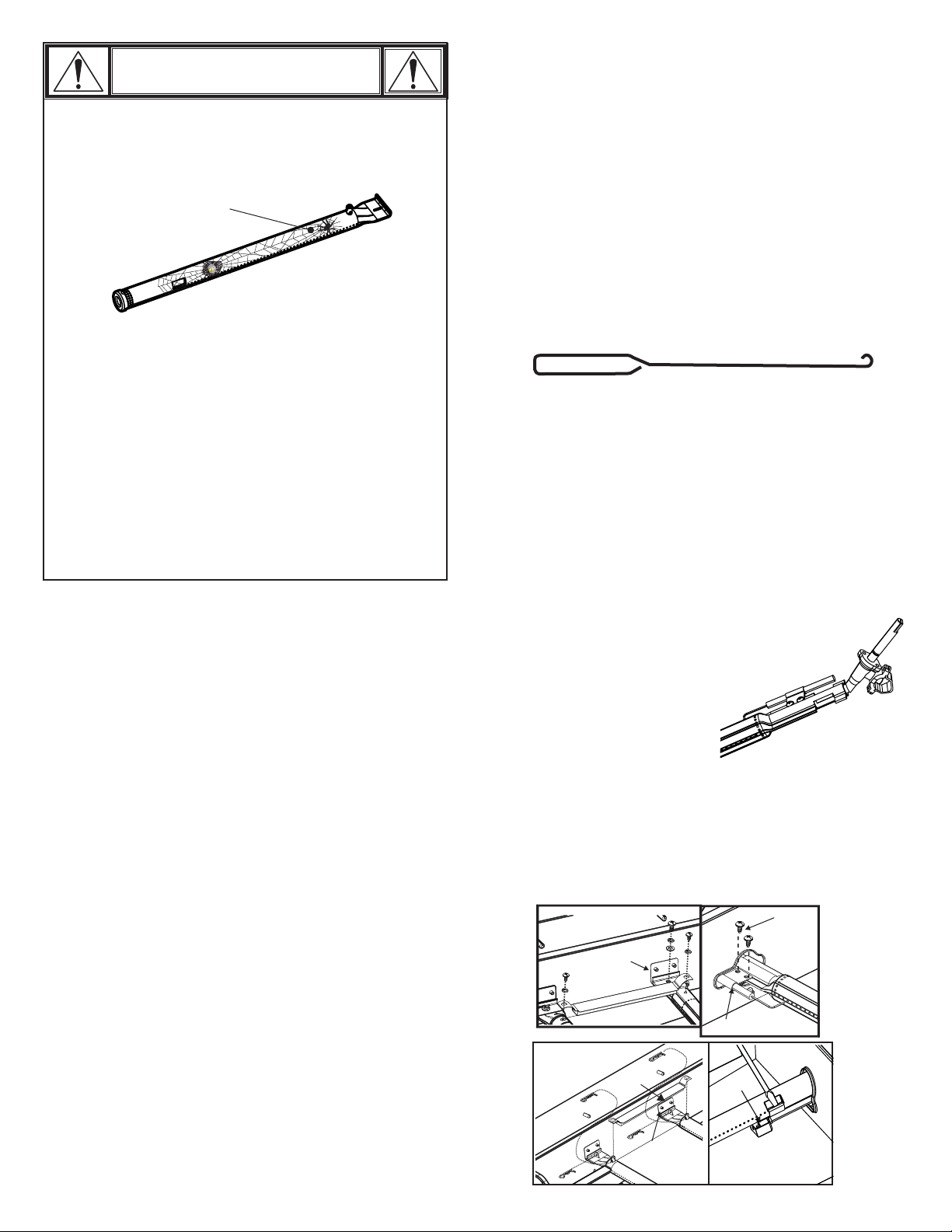
CAUTION
SPIDER ALERT!
SPIDER AND WEBS
INSIDE BURNER
Your burner might be different
If your grill is getting hard to light or the flame is weak,
check and clean the venturis and burners.
Cleaning the Burner Assembly
Follow these instructions to clean and/or replace parts of burner
assembly or if you have trouble igniting grill.
1. Turn gas off at control knobs and LP cylinder.
2. Remove cooking grates and heat tents.
3. Remove carryover tubes and hardware securing burners.
4. Detach electrode from burner.
NOTE: Removal/Detachment method will depend on the
burner configuration. See different configurations in
illustrations below.
5. Carefully lift each burner up and away from valve openings.
We suggest three ways to clean the burner tubes. Use
the one easiest for you.
(A) Bend a stiff wire (a light weight coat hanger works well)
into a small hook. Run the hook through each burner
tube several times.
Spiders or small insects are known to create “flashback”
problems by building nests and laying eggs in the grill’s
venturi or burner, obstructing the flow of gas. The backup gas can ignite behind the control panel. This
flashback can damage your grill and cause injury. To
prevent flashbacks and ensure good performance the
burner and venturi tube assembly should be removed
and cleaned when ever the grill has been idle for an
extended period of time.
General Grill Cleaning
• Do not mistake brown or black accumulation of grease and
smoke for paint. Interiors of gas grills are not painted at the
factory (and should never be painted). Apply a strong solution
of detergent and water or use a grill cleaner with scrub brush on
insides of grill lid and bottom. Rinse and allow to completely air
dry. Do not apply a caustic grill/oven cleaner to painted
surfaces.
• Plastic parts: Wash with warm soapy water and wipe dry.
• Do not use citrisol, abrasive cleaners, degreasers or a
concentrated grill cleaner on plastic parts. Damage to and
failure of parts can result.
• Porcelain surfaces: Because of glass-like composition, most
residue can be wiped away with baking soda/water solution or
specially formulated cleaner. Use nonabrasive scouring
powder for stubborn stains.
• Painted surfaces: Wash with mild detergent or nonabrasive
cleaner and warm soapy water. Wipe dry with a soft
nonabrasive cloth.
• Cooking surfaces: If a bristle brush is used to clean any of
the grill cooking surfaces, ensure no loose bristles remain on
cooking surfaces prior to grilling. It is NOT recommended to
clean cooking surfaces while grill is hot.
• Food probe: Not dishwasher safe. Do not immerse or soak in
water. Wash with warm soapy water and wipe dry.
(B) Use a narrow bottle brush with a flexible handle (do not
use a brass wire brush). Run the brush through each
burner tube several times.
(C) Wear eye protection: Use an air hose to force air into
the burner tube and out the burner ports. Check each port
to make sure air comes out each hole.
6. Wire brush entire outer surface of burner to remove food
residue and dirt.
7. Clean any blocked ports with a stiff wire such as an open
paper clip.
8. Check burner for damage due to normal wear and corrosion,
some holes may become enlarged. If any large cracks or holes
are found, replace burner.
VERY IMPORTANT: Burner tubes must reengage
valve openings. See illustrations at right.
Correct burner-tovalve engagement
9. Attach electrode to burner.
10. Carefully replace burners.
11. Attach burners to brackets on firebox.
12. Reposition carryover tubes and attach to burners. Replace
heat tents and cooking grates.
13. Before cooking again on grill, perform a “Leak Test” and
“Burner Flame Check”.
Remove
Firebox
Firebox Burner
Support
Carryover tube
Firebox
Electrode
Electrode
Carryover tube
screws
Firebox Burner
Support
9
Pry off electrode with
a flate blade
screwdriver
Page 10
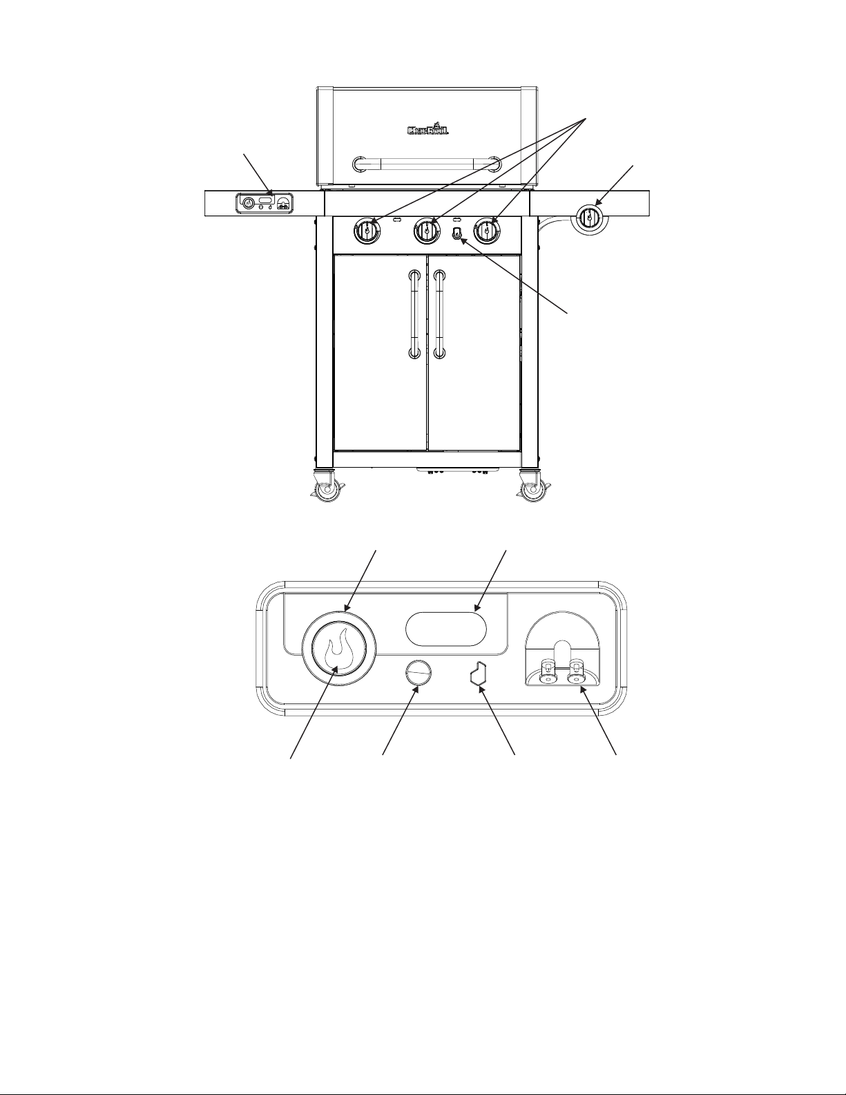
SmartChef Controls
Main Burner Control Knobs
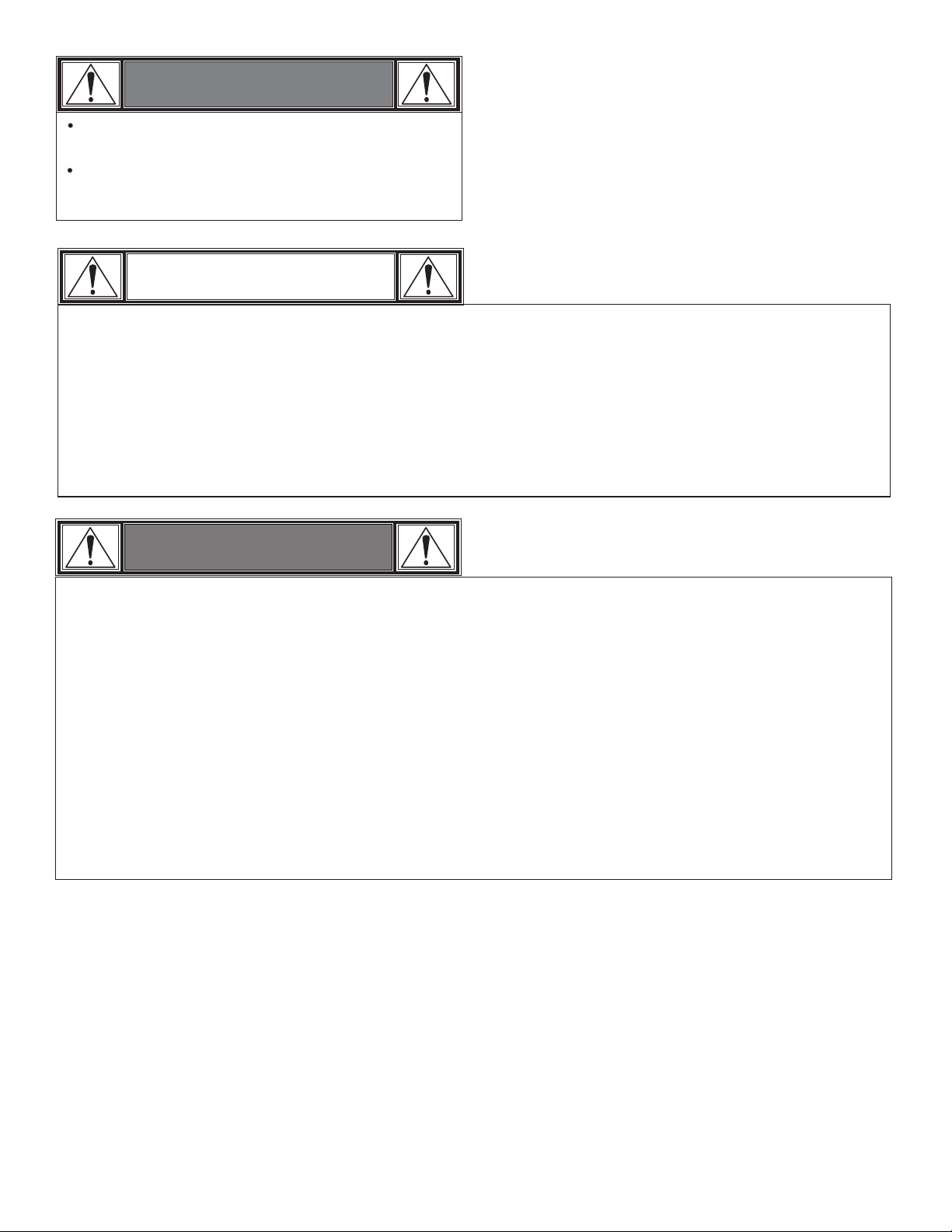
SmartChef Control Panel
Side Burner Control Knob
Electronic Ignitor
Light Ring Tank Level Indicator
Control Start/Stop button ON/OFF button DADO button
● Control Start/Stop Button - Initiates or stops control mode.
● Light Ring - Provides general grill info at a glance. Generally,
Green = Ready, Orange = Lit, Red = Error
● Meat Probe Ports - Plug integrated probes into these ports.
● On/Off Button – Turn Power to the unit ON/OFF. Must be
ON to use main burners of grill. Side burner can be operated
independently.
● Tank Indicator – Tank image flashes when you are running
low on gas. Tank image is solid when the tank is expected to
be empty.
Meat Probe Ports
● DADO Button – WiFi/DADO functions. ON = WiFi
Connected. OFF =Attempting to Connect. Flashing = Not
Connected or has Firmware update available.
When not connected, pressing DADO button will attempt to
rejoin the WiFi settings programmed. If a Firmware update is
available, pressing the DADO button will begin the download.
Press and hold to reset WiFi settings to default. Open app or
visit charbroil.com/smartchefgrill for more detail information.
10
Page 11

SmartChef Operating Instructions
The following instructions apply to the main burners only.
The side burner is not controlled by the SmartChef system.
Manual Operation:
Your grill may be operated as a conventional grill. No interaction
with the SmartChef control panel is necessary to operate in this
mode. After lighting your grill, turn your burner valve control
knobs to the desired setting to begin your cook. While in manual
operation, you may still monitor the following features through
your Char-Broil app:
1) Burner flame status – your Char-Broil app will indicate whether
there is a flame present at each burner. At the grill, LED lights
around each knob wilI illuminate when there is flame present.
If there is no flame at all 3 burners for 30 seconds or at a
single burner for 2 minutes, the grill will shutdown to prevent
unburned gas from continuing to flow. ALL knobs must then be
turned to the OFF position and lighting instructions followed in
order to restart grill.
2) Meat Probe temperatures – your Char-Broil app will display
the temperatures of up to two meat probes. Insert probe into
center of meat for most accurate temperature.
3) Grill Temperature – your Char-Broil app will display the current
grill temperature.
4) Tank level – your Char-Broil app will notify you when your tank
level is low.
Controlled Operation:
To preheat and/or cook at a specified temperature:
1) Light grill per lighting instructions.
2) Turn all main burner control knobs to High position.
3) Press Control Start/Stop Button on SmartChef Control Panel
located on grill. Light ring will indicate controlled operation.
4) In the Char-Broil app, set your desired temperature. Your grill
will maintain this temperature throughout the cook.
Temperature may be adjusted within the app at any time.
5) To change to manual operation after a controlled preheat,
press and hold (2 seconds) the Control Start/Stop Button on
the SmartChef Control Panel, then adjust burner control
knobs as desired. If any burner control knob is turned away
from High prior to pressing the Control Start/Stop button, a
notification will alert you to press and hold the button on the
SmartChef Control Panel. If the button is not pushed, the grill
will shutdown to ensure your food is not unintentionally
overcooked.
To follow a cook profile (controlled cook/recipe):
1) Light grill per lighting instructions.
2) Turn all main burner control knobs to High position.
3) Press Control Start/Stop Button on SmartChef Control Panel
located on grill. Light ring will indicate controlled operation.
4) In the Char-Broil app,
a. Choose your desired food.
b. Select your foods attributes, e.g. weight, cut, etc..
c. Tap the “Next” button.
d. Wait until you are notified to add your food to the grill.
Please note, the grill may need to finish the pre-heat cycle
first.
e. When instructed, press the Start button on the grill to start
cooking.
5) To change to manual operation after a controlled cook, press
and hold (2 seconds) the Control Start/Stop Button on the
SmartChef Control Panel, then adjust burner control knobs as
desired.
If any burner control knob is turned away from High prior to
pressing the Control Start/Stop button, a notification will alert you
to press the button on the SmartChef Control Panel.
If the button is not pushed, the grill will shutdown to ensure your
food is not unintentionally overcooked.
In manual or controlled operation, you may turn your grill off in
the following ways:
1) Turn all burner control knobs to the OFF position.
2) Turn SmartChef control panel off using On/Off button, or by
unplugging. ALL knobs should then be returned to the OFF
position. Grill cannot be restarted until ALL knobs have first
been turned to the OFF position, then lighting instructions
followed to light grill. If knobs are not returned to OFF position,
an error notification will be displayed on the app and light ring.
11
Page 12
WARNING
Keep any electrical supply cord away from any
heated surface.
Use the shortest length extension cord required.
Do not connect 2 or more extension cords together.
IMPORTANT
Ÿ Since 1971 the National Electric Code (NEC) has required Ground Fault Interrupter devices on all outdoor
circuits.
Ÿ If your residence was built before 1971, check with a qualified electrician to determine if a Ground Fault
Interrupter protector exists.
Ÿ Do not use this appliance if the circuit does not have GFI protection.
Ÿ Do not plug this appliance into an indoor circuit.
WARNING
1. To protect against electric shock, do not immerse cord or plugs in water or other liquid.
2. Unplug from the outlet when not in use and before cleaning. Allow to cool before putting on or taking off parts.
3. Do not operate grill with a damaged cord, plug, or after the appliance malfunctions or has been damaged in any
manner.
4. Do not let the cord hang over the edge of a table or touch hot surfaces.
5. Do not use an outdoor cooking gas appliance for purposes other than intended.
6. When connecting, first connect plug to the outdoor cooking gas appliance then plug appliance into the outlet.
7. Use only a Ground Fault Interrupter(GFI) protected circuit with this outdoor cooking gas appliance.
8. Never remove the grounding plug or use with an adapter of 2 prongs.
9. Use only extension cords with a 3 prong grounding plug, rated for the power of the equipment, and approved for
outdoor use with a W-A marking.
12
Page 13

LIMITED WARRANTY
This warranty only applies to units purchased from an authorized retailer. Manufacturer warrants to the original consumer-purchaser only that this
product shall be free from defects in workmanship and materials after correct assembly and under normal and reasonable home use for the periods
indicated below beginning on the date of purchase*. The manufacturer reserves the right to require that defective parts be returned, postage and or
freight pre-paid by the consumer for review and examination.
SCOPE OF COVERAGE PERIOD OF COVERAGE TYPE OF FAILURE COVERAGE
Stainless Burner
Firebox, Lid, Cooking Grate and Emitters
All Other Parts
*Note: A dated sales receipt WILL be required for warranty service.
The original consumer-purchaser will be responsible for all shipping charges for parts replaced under the terms of this limited warranty.
This limited warranty is applicable in the United States and Canada only, is only available to the original owner of the product and is not transferable.
Manufacturer requires proof of your date of purchase. Therefore, you should retain your sales slip or invoice. Registering your product is not a
substitute for proof of purchase and the manufacturer is not responsible for or required to retain proof of purchase records.
This limited warranty applies to the functionality of the product ONLY and does not cover cosmetic issues such as scratches, dents, corrosions or
discoloring by heat, abrasive and chemical cleaners or any tools used in the assembly or installation of the appliance, surface rust, or the
discoloration of stainless steel surfaces. Paint is not warranted and will require touch up. RUST is not considered a manufacturing or materials defect.
This limited warranty will not reimburse you for the cost of any inconvenience, food, personal injury or property damage.
ITEMS MANUFACTURER WILL NOT PAY FOR:
1. Shipping cost, standard or expedited, for warranty and replacement parts
2. Service calls to your home.
3. Repairs when your product is used for other than normal, single-family household or residential use.
4. Damage, failures, or operating difficulties resulting from accident, alteration, careless handling, misuse, abuse, fire, flood,
acts of God, improper installation or maintenance, installation not in accordance with electrical or plumbing codes, or use
of products not approved by the manufacturer.
5. Any food loss due to product failures or operating difficulties.
6. Replacement parts or repair labor costs for units operated outside the United States or Canada.
7. Pickup and delivery of your product.
8. Repairs to parts or systems resulting from unauthorized modifications made to the product.
9. The removal and/or reinstallation of your product.
DISCLAIMER OF IMPLIED WARRANTIES and LIMITATION OF REMEDIES
Repair or replacement of defective parts is your exclusive remedy under the terms of this limited warranty. In the event of parts availability issues,
the manufacturer reserves the right to substitute like or similar parts that are equally functional.
Manufacturer will not be responsible for any consequential or incidental damages arising from the breach of either this limited warranty or any
applicable implied warranty, or for failure or damage resulting from acts of God, improper care and maintenance, grease fire, accident, alteration,
replacement of parts by anyone other than Manufacturer, misuse, transportation, commercial use, abuse, hostile environments (inclement weather,
acts of nature, animal tampering), improper installation or installation not in accordance with local codes or printed manufacturer instructions.
THIS LIMITED WARRANTY IS THE SOLE EXPRESS WARRANTY GIVEN BY THE MANUFACTURER. NO PRODUCT PERFORMANCE
SPECIFICATION OR DESCRIPTION WHEREVER APPEARING IS WARRANTED BY MANUFACTURER EXCEPT TO THE EXTENT SET
FORTH IN THIS LIMITED WARRANTY. ANY IMPLIED WARRANTY PROTECTION ARISING UNDER THE LAWS OF ANY STATE,
INCLUDING IMPLIED WARRANTY OF MERCHANTABILITY OR FITNESS FOR A PARTICULAR PURPOSE OR USE, IS HEREBY
LIMITED IN DURATION TO THE DURATION OF THIS LIMITED WARRANTY.
Neither dealers nor the retail establishment selling this product has any authority to make any additional warranties or to promise remedies
in addition to or inconsistent with those stated above. Manufacturer's maximum liability, in any event, shall not exceed the purchase price of the
product paid by the original consumer.
NOTE: Some states do not allow an exclusion or limitation of incidental or consequential damages, so some of the above limitations or exclusions
may not apply to you. This limited warranty gives you specific legal rights as set foth herein. You may also have other rights which vary from state
to state. In the state of California only, if refinishing or replacement of the product is not commercially practicable, the retailer selling this product or
the Manufacturer will refund the purchase price paid for the product, less the amount directly attributable to use by the original consumer-purchaser
prior to discovery of the nonconformity. In addition, in the state of California only, you may take the product to the retail establishment selling this
product in order to obtain performance under this limited warranty.
10 years from date of purchase*
3 years from date of purchase*
1 year from date of purchase*
PERFORATION, MANUFACTURING,
AND MATERIAL DEFECTS ONLY
If you wish to obtain performance of any obligation under this limited warranty, you should
Columbus, GA 31902-1240
Consumer returns will not be accepted unless a valid Return Authorization is first acquired. Authorized returns are clearly marked on the outside of
the package with an RA number and the package is shipped freight/postage pre-paid. Consumer returns that do not meet these standards will be
refused.
write to:
Consumer Relations
P. O. Box 1240
13
Page 14
ÍNDICE DE MATERIAS
Por su propia seguridad. . . . . . . . . . . . . . . . . . . . . . . . . 14-16
Uso y mantenimiento. . . . . . . . . . . . . . . . . . . . . . . . . . . 16-21
ADVERTENCIA
PELIGRO
Sólo para uso particular. No lo use para fines comerciales.
Controles SmartChef . . . . . . . . . . . . . . . . . . . . . . . . . . . 22-24
Garantía limitada. . . . . . . . . . . . . . . . . . . . . . . . . . . . . . . . . 25
Armado . . . . . . . . . . . . . . . . . . . . . . . . . . . . . . . . . . . . . 26-52
Resolución de problemas . . . . . . . . . . . . . . . . . . . . . . . 55-56
Vista esquemática de las piezas. . . . . . . . . . . . . . . . . . . . . 58
Lista de piezas . . . . . . . . . . . . . . . . . . . . . . . . . . . . . . . . . . 60
Lista de herrajes . . . . . . . . . . . . . . . . . . . . . . . . . . . . . . 61-62
Tarjeta de inscripción . . . . . . . . . . . . . . . . . . . . . . . . . . . . . 63
A LA PERSONA QUE INSTALE O
ENSAMBLE ESTA PARRILLA:
Deje este manual al cliente.
AL CONSUMIDOR:
Conserve este manual para que lo pueda consultar en el futuro.
Símbolos de seguridad
Los símbolos y las casillas ilustradas más adelante explican lo
que significa cada encabezado. Lea y cumpla lo indicado en los
mensajes que se encuentran en todo el manual.
ADVERTENCIA
PELIGRO
ADVERTENCIA: Indica una situación potencialmente
peligrosa o una práctica insegura que, de no evitarse,
podría causar lesiones leves o menores.
ESTA PARRILLA SOLO SE PUEDE
USAR EN EXTERIORES.
PELIGRO
Si siente olor a gas:
1. Cierre el paso de gas al aparato.
2. Apague toda llama al descubierto.
3. Abra la tapa.
4. Si el olor continúa, guarde lejos de la aplicación y
llame inmediatamente su surtidor del gas o su
cuerpo de bomberos.
ADVERTENCIA
1. No guarde ni use gasolina ni otros gases o líquidos
inflamables cerca de éste ni de cualquier otro aparato.
2. No guarde un tanque de gas propano, que no esté
conectado, cerca de éste ni de cualquier otro aparato.
ADVERTENCIA
No intente reparar ni modificar la unidad de la
manguera/la válvula/el regulador debido a un
"supuesto" defecto. Toda modificación a esta unidad
anulará la garantía y creará el riesgo de una fuga de
gas e incendio. Use únicamente repuestos
autorizados, suministrados por el fabricante.
PELIGRO
ADVERTENCIA
ADVERTENCIA: Indica una situación potencialmente
peligrosa que, de no evitarse, podría causar la muerte o
lesiones graves.
PELIGRO
PELIGRO: Indica una situación peligrosa inminente que,
de no evitarse, ocasionará la muerte o lesiones graves.
Outils requis pour l'assemblage :
Clé réglable (non comprise)
Tournevis (non comprise)
Clé mixte de 7/16 po (non comprise)
Clé mixte de 3/4 po (non comprise)
Si durante el funcionamiento las llamas se apagan
(Huele a gas o no se ve la llama)
1. Gire los controles del quemador a APAGADO.
2. Abra la tapa.
3. Espere 5 minutos y repita el procedimiento de
encendido.
Si el quemador se apaga, el gas continuará escapando
del quemador y puede accidentalmente encenderse con
riesgo de lesiones.
ADVERTENCIA
No cubra las rejillas con papel aluminio ni con ningún otro
material. Este bloqueará la ventilación del quemador y
creará situaciones peligrosas que podrían provocar daños
materiales o lesiones corporales.
14
Page 15
ADVERTENCIA
ADVERTENCIA
PELIGRO
El no cumplir con todas instrucciones del fabricante
puede ocasionar graves y/o daños materials.
ADVERTENCIA
PELIGRO
Antes de empezar a ensamblar la parrilla y cocinar, lea y siga
todas las indicaciones de seguridad, las instrucciones de
ensamblado y las instrucciones de uso y de cuidado
ADVERTENCIA
PELIGRO
Ciertas pueden tener bordes cortantes. Si es necesario, use
guantes protectores.
ADVERTENCIA
PELIGRO
Fuego de Grasa
• No es posible apagar los fuegos provocados por la
grasa cerrando la tapa. Por razones de seguridad, las
parrillas tienen aberturas de ventilación.
• No use agua para apagar los fuegos provocados por
la grasa. Esto puede ocasionar lesiones. Si surge un
fuego provocado por la grasa, cierre las perillas y el
tanque de gas.
• Si el asador no se ha limpiado regularmente, podría
ocurrir fuego causado por la grasa que podría dañar el
producto. Preste mucha atención mientras precalienta
o quema los residuos de comida para asegurar que no
se cause fuego debido a la grasa.
• La mejor forma de prevenir el incendio de grasas es
limpiar frecuentemente la parrilla siguiendo las
instrucciones de Limpieza general de la parrilla y
Limpieza del conjunto quemador.
El uso de macetas de más de 6 cuartos de la capacidad
podría superar límite de peso de lado el quemador
plataforma o lado plataforma lo que resulta en el fracaso
de la parrilla carrito componentes.
PELIGRO
• NUNCA guarde los cilindros de gas de repuesto
debajo del aparato, cerca del mismo, ni en áreas
cerradas.
ADVERTENCIA
PROPOSICION 65 DEL ESTADO DE CALIFORNIA
1. En el estado de California se sabe que los
subproductos de la combustión, que se producen al
usar este producto, contienen substancias químicas
que causan cáncer, defectos congénitos u otras
lesiones al aparato reproductor.
2. Este producto contiene substancias químicas,
incluyendo el plomo y compuestos de plomo, que
en el estado de California se sabe que las causan
cáncer, defectos congénitos u otras lesiones al
aparato reproductor.
Lávese las manos después de manipular este
• Nunca cargue el tanque con más del 80% de su
capacidad.
• Los tanques de gas propano de repuesto
sobrecargados o mal llenados son peligrosos, ya que
la válvula de seguridad puede dejar salir gas. Esto
puede provocar incendios intensos que pueden
causar daños materiales, lesiones graves o la muerte.
• Si observa, huele o escucha una fuga de gas, aléjese
de inmediato del cilindro y del aparato, y llame a los
bomberos.
15
Page 16
Medidas de seguridad para la instalación
• Utilice la parrilla, tal como se compró, sólo con LP
(propano), el gas y el regulador / válvula de montaje
suministrado.
• La instalación de la parrilla debe cumplir con las
disposiciones de los códigos locales, o, en su defecto, con el
National Fuel Gas Code (o Código nacional sobre gases
combustibles), y las normas NFPA 54 / ANSI Z223.1 y
Natural Gas and Propane Installation Code (Código de la
instalación del gas natural y del propano), CSA B149.1.
• Todos los accesorios eléctricos (tal como el asador) deben
estar conectados a tierra de conformidad con los códigos
locales, o con el National Electrical Code (Código nacional
sobre electricidad), ANSI / NFPA 70. Mantenga todo cable
eléctrico o tubería de suministro de combustible alejados de
las superficies calientes.
• Esta parrilla únicamente cuenta con la certificación de
seguridad para ser usada en los Estados Unidos. No la
modifique para usarla en ningún otro lugar. Cualquier
modificación puede poner en peligro su seguridad.
USO Y MANTENIMIENTO
Remoción, transporte y almacenamiento del
tanque de gas propano
• CIERRE todas las perillas de control y la válvula del tanque.
Gire la tuerca de unión en sentido contrario a las agujas del
reloj, a mano solamente; no use herramientas para
desconectarla. Afloje el tornillo, ubicado debajo de la repisa, o
desconecte el dispositivo de retención del tanque, luego
levante el tanque de gas para sacarlo del carrito. Instale la
tapa de seguridad en la válvula del tanque de gas. Use
siempre la tapa y la correa que vienen con la válvula. Si la
tapa de seguridad no se usa tal como se indica, esto
puede ocasionar lesiones o daños materiales graves.
• Los tanques de gas desconectados, guardados o en
transporte, deben tener instalada la tapa de seguridad (como
se ilustra). No guarde el tanque de gas en sitios cerrados, tales
como cocheras, garajes, porches, patios techados u otras
edificaciones.
• No guarde un tanque de gas en un área donde el juegan niños.
Válvula del
tanque de gas
Tapa de seguridad
Tira de sujeción
Tanque de gas propano
• El tanque de gas que use con su parrilla debe cumplir los
siguientes requisitos:
• Use únicamente tanques de gas que tengan las siguientes
medidas obligatorias: 12 PULGADAS (30.5 cm) (diámetro) x 18
PULGADAS (45.7 cm) (altura), con una capacidad máxima de
20 lb. (9 kg).
• Los tanques de gas propano deben ser fabricados y
codificados según las especificaciones para tanques de gas
propano del Departamento de Transporte de los Estados
Unidos (DOT), oen Canadá, segúnlas normas CAN/CSA-B339,
sobre cilindros,esferas y tubos para el transporte de
mercancías peligros as del Ministeriode Transportes de
Canadá(CT). El código se encuentra en el collarín del tanque
de gas.
• La válvula del tanque de gas debe tener:
•Una salida de tipo 1, compatible con el
regulador o la parrilla.
•Una válvula de paso de seguridad.
•Un dispositivo de seguridad volumétrica
(OPD por sus siglas en inglés) certificado
por UL. Esta característica de seguridad
OPD se identifica mediante una manilla de
forma triangular. Use únicamente tanques
equipados con válvulas de este tipo.
• El cilindro de gas LP debe estar en posición vertical para la
eliminación de vapores e incluir un cuello para proteger la
válvula del cilindro de gas LP. Siempre mantenga los cilindros
en posición vertical durante el uso, transporte y
almacenamiento.
Tanque de gas en posición
vertical para extraer el vapor
Manilla del
dispositivo de
seguridad
volumétrica
El gas propano (GLP)
• Es atóxico, inodoro e incoloro en el momento en que se
produce. , al gas propano se le ha Para su seguridad
incorporado un olor (parecido al de la col podrida), de modo que
se pueda oler.
• El gas propano es sumamente inflamable y se puede
encender en forma inesperada al mezclarse con el aire.
Carga de los tanques de gas propano
• Recurra solamente a vendedores autorizados y con experiencia.
• purgar el tanque nuevo El vendedor de gas debe antes de
cargarlo.
• NUNCA El vendedor no debe cargar el tanque de gas con más
del 80% de su volumen. El volumen de propano en el tanque
puede variar con la temperatura.
• Si el regulador está empañado, eso indica que el tanque está
sobrecargado. Cierre de inmediato la válvula del tanque y
solicite ayuda del vendedor de gas propano.
• No deje escapar gas propano a la atmósfera. Ésta es una
práctica peligrosa.
• Solicite ayuda del vendedor de propano o de los bomberos,
para vaciar el gas de su tanque. Identifique a los vendedores
autorizados de propano de su región en la sección de
"compañías de gas" de la guía telefónica.
16
Page 17
Cambio del tanque de gas
• Muchos comerciantes minoristas que venden parrillas, le
ofrecen la opción de cambiar su tanque de gas vacío mediante
un servicio de recambio. Emplee únicamente empresas de
recambio de buena reputación, que inspeccionen, carguen con
precisión, verifiquen y certifiquen sus cilindros. Cambie su
tanque sólo por otros tanques equipados con el
dispositivo de seguridad volumétrica que se describe en
la sección de tanques de gas de este manual.
• Siempre mantenga los tanques de gas, nuevos y de repuesto,
en posición vertical durante su uso, su transporte o su
almacenamiento.
• Verifique que el tanque de gas, nuevo o de recambio, no
tenga fugas ANTES de conectarlo a la parrilla.
• Coloque la tapade seguridad sobre la salida de la válvula del
tanque de gas cuando no lo use. Instale únicamente el tipo de
tapade seguridad que viene con la válvula del tanque. Los
otros tipos de tapas o tapones pueden dejar escapar el gas
propano.
Prueba para detectar fugas del tanque de gas
propano
Por su propia su seguridad
• Se debe efectuar la prueba para detectar fugas cada vez que
se cambie o se recargue el tanque.
• No fume durante la prueba para detectar fugas.
• No use una llama al descubierto para comprobar si el tanque
tiene fugas.
• La prueba para detectar fugas de la parrilla se debe efectuar
al aire libre, en un área bien ventilada, alejada de toda fuente
de ignición tal como los artefactos a gas o eléctricos. Durante
la prueba para detectar fugas, mantenga la parrilla alejada de
las llamas al descubierto o de las chispas.
• Use una brocha de pintura limpia y una solución de 50/50 de
agua y jabón suave. Pinte con la solución jabonosa las áreas
indicadas por las flechas en la ilustración que sigue.
• No use productos de limpieza del hogar. Esto puede
dañar los componentes del circuito de gas.
Como conectar el regulador al tanque de gas
propano
1. El tanque de gas debe quedar bien fijado a la parrilla.
(Lea la sección de ensamblado.)
2. Gire todas las perillas de control a la posición APAGADO (OFF).
3. CIERRE el tanque de gas, girando la manilla de la válvula
en el sentido de las agujas del reloj, hasta que se detenga.
4. Retire la tapa de seguridad de la válvula del cilindro de gas LP.
Siempre use la tapa y correa, si se suministraron con la válvula.
Cierre en el sentido de
las agujas del reloj
Manilla del
¡No use un tapón
POL para transporte
(la pieza de plástico
con roscas en el
exterior)! Anulará la
Válvula de
seguridad
característica de
seguridad de la
válvula.
Correa y tapa
5. Sostenga el regulador e inserte el manguito
de unión en la válvula del tanque de gas.
Apriete a mano la tuerca de unión, mientras
sostiene el regulador en línea recta con la
válvula del tanque, para no saltar ninguna
rosca de la conexión.
El manguito de unión debe
quedar centrado en la
válvula del tanque de gas.
Recto
dispositivo de
seguridad
volumétrica
Salida tipo 1,
con rosca
exterior
Tuerca de
unión
ADVERTENCIA
Si aparecen burbujas que aumentan de tamaño, no use ni
mueva el tanque de gas. ¡Comuníquese con el proveedor
de gas propano o con los bomberos!
Sostenga la tuerca de unión y el
regulador, como se ilustra, para
conectarlos bien a la válvula del
tanque.
6. Gire la tuerca de unión en el sentido de las agujas del reloj,
apretándola hasta que no se mueva más. El regulador formará
un sello en el dispositivo de seguridad de la válvula del tanque,
lo que creará cierta resistencia. Se deberá hacer girar la
tuerca entre un cuarto y tres cuartos de vuelta adicionales,
para completar la conexión. Apriétela a mano, no use
herramientas.
NOTA:Si no puede completar la conexión, desconecte
el regulador repita los pasos 5 y 6. Si a pesar de
haberlo hecho, todavía no puede completar la conexión,
¡no use este regulador!
PELIGRO
No introduzca ninguna herramienta ni ningún objeto extraño
en la salida de la válvula ni en la válvula de seguridad.
Puede dañarla y causar una fuga. Las fugas de gas propano
pueden causar explosiones, incendios, lesiones graves o la
muerte.
17
Page 18
ADVERTENCIA
ADVERTENCIA
• No use la parrilla sin antes haber verificado que no tenga
fugas.
• Si en algún momento detecta una fuga, ¡DETÉNGASE!
Apague la fuente de gas y corrija la fuga.
• Si no puede detener una fuga de gas cerrando la zona baja
vavle del tanque de gas y llame a los bomberos.
Prueba para detectar fugas de las válvulas, las mangueras y
el regulador
1. Cierre todas las perillas de control de la parrilla.
2. Cerciórese de que el regulador esté bien conectado al
tanque de gas.
3. Enchufe el cable de alimentación y encienda el Panel de
Control.
4. Abra por completo la válvula del tanque, girando la manilla en
sentido contrario a las agujas del reloj. Si escucha un sonido
de ráfaga, cierre de inmediato el paso de gas. La conexión
tiene una fuga considerable. Corrija esta situación antes de
continuar.
5. Aplique solución jabonosa con la brocha, en las áreas
marcadas con un círculo en la ilustración que sigue. u otros
accesorios similares en su parrilla.
NOTA: Para mayor claridad, no
se ilustra la máscara de del
estante del quemador lateral y
otras partes.
NOTA: Su parrilla puede
no tener una hornilla
lateral.
• El aparato a gas para uso al aire libre no ha sido diseñado
para ser instalado en embarcaciones.
• El aparato a gas para uso al aire libre no ha sido
diseñado para ser instalado en vehículos de recreo.
• Nunca trate de conectar esta parrilla al sistema de gas
propano independiente de un remolque de recreo o de una
casa rodante.
Consejos de seguridad
• Verifique que la tuerca de unión esté bien apretada antes de
abrir la válvula del tanque de gas.
• Cuando la parrilla no esté en uso, apague las perillas de
control, la válvula del cilindro de gas LP y desconecte el
cable de alimentación.
• Nunca mueva la parrilla cuando la esté usando o mientras
esté caliente.
• Algunas superficies pueden estar calientes durante el uso.
Use utensilios para parrilla de mango largo y guantes para
hornear, para evitar quemaduras y salpicaduras.
• El peso máximo que soportan el quemador lateral y la repisa
lateral es de 10 lb.
• La bandeja o el recipiente para la grasa debe estar colocado
siempre que use la parrilla, y lo debe vaciar cada vez
después de usarla. No retire la bandeja o el recipiente para la
grasa hasta que la parrilla se haya enfriado por completo.
• Limpie la parrilla con frecuencia; de preferencia cada vez
después de usarla. Si utiliza un cepillo de cerdas para limpiar
las superficies para cocinar, antes de usar la parrilla verifique
que no queden cerdas sueltas sobre éstas. Se recomienda no
limpiar las superficies para cocinar cuando la parrilla esté aún
caliente.
• Si observa que de la parrilla caen gotas de grasa u otras
sustancias calientes sobre la válvula, la manguera o el
regulador, cierre inmediatamente el paso de gas. Establezca la
causa, corrija el problema, limpie e inspeccione la válvula, la
manguera y el regulador, antes de proseguir. Haga una prueba
para detectar fugas.
• Mantenga limpias y sin residuos las aberturas de ventilación
del recinto para el cilindro de gas (del carrito de la parrilla).
• No guarde objetos ni materiales dentro del carrito de la parrilla
que puedan bloquear la circulación del aire de la combustión a
la parte inferior del tablero de control o de la caja de la cámara
de combustión.
• El regulador puede emitir un sonido zumbante o sibilante
durante su uso. Esto no afectará la seguridad ni el uso de la
parrilla.
• Si tiene un problema con la parrilla vea la sección "solución
de problemas" o visite charbroil.com/smartchefgrill.
• Si el regulador se empaña, apague inmediatamente la parrilla
y cierre la válvula del tanque de gas. Esto indica que existe un
problema con el tanque y no debe ser usado en ningún otro
producto. ¡Devuélvalo al proveedor!
5. Si aparecen burbujas que aumentan de tamaño, existe una
fuga. Cierre de inmediato la válvula del tanque de gas y
vuelva a apretar las conexiones. Si no puede eliminar las
fugas, no intente repararlas. Solicite una pieza de repuesto.
Encargue las piezas nuevas indicando el número de serie, de
modelo y el nombre de las piezas que requiera (vea la lista de
piezas), llamando al centro de servicio para parrillas
6. Después de hacer una prueba para detectar fugas, cierre
siempre la válvula del tanque de gas, girando la manilla en el
sentido de las agujas del reloj.
18
Page 19
ADVERTENCIA
Para usar su parrilla en forma segura y para evitar
lesiones graves:
• No deje que los niños usen la parrilla ni que jueguen
cerca de la misma.
• Mantenga el área de la parrilla limpia y sin materiales
combustibles.
• No obstruya los orificios laterales ni los de la parte
posterior de la parrilla.
• Revise periódicamente las llamas del quemador.
• Use la parrilla sólo en lugares bien ventilados. NUNCA la
use en lugares cerrados tales como cocheras, garajes,
porches, patios techados o debajo de superficies de
ningún tipo.
• No use carbón ni briquetas de cerámica en una parrilla a
gas.
• No cubra las rejillas con papel aluminio ni con ningún otro
material. Este bloqueará la ventilación del quemador y
creará situaciones peligrosas que podrían provocar
daños materiales o lesiones corporales.
• Use la parrilla al menos a 3 pies de distancia de
cualquier pared o superficie. Deje un espacio de 10
pies entre la parrilla y los objetos que puedan incendiarse
o que sean fuentes de ignición, tal como las llamas piloto
de calentadores de agua, aparatos eléctricos
conectados, etc.
Cómo usar el encendedor
• No se incline sobre la parrilla al encenderla.
1. Gire las válvulas de control de gas del quemador a
(APAGADO).
2. Conecte el cable de alimentación. Presione el botón de
encendido para encender el panel de control.
3. Abra la tapa durante el encendido o al volver al encender.
4. ABRA el gas en el cilindro de gas LP.
5. Para encender, presione y gire la perilla del quemador a
ALTO. Inmediatamente, presione y mantenga presionado el
botón de ENCENDIDO ELECTRÓNICO hasta que el
quemador encienda.
6. Si NO enciende en 5 segundos, gire la perilla de control del
quemador a la posición APAGADO, espere 5 minutos y
repita el procedimiento de encendido. Si el encendedor no
funciona, siga las instrucciones de encendido con fósforo
que aparecen en el manual.
7. Repita los pasos 4 al 5 para encender los demás
quemadores principales.
ADVERTENCIA
CIERRE los controles y la fuente de suministro de gas
cuando no la use.
ADVERTENCIA
PELIGRO
3pi
• NUNCA trate de encender el quemador con la tapa
cerrada. Las acumulaciones de gas no encendido en
las parrillas tapadas son peligrosas.
• Nunca use la parrilla si el tanque de gas no está en
la posición correcta que se especifica en las
instrucciones de armado.
• Siempre cierre la válvula del tanque de gas y retire la
tuerca de unión antes de mover el tanque del sitio
específico de uso.
• Para personas que viven en apartamentos:
Pídale al administrador que le indique los requisitos y los
códigos contra incendios que corresponden al uso de
parrillas de gas propano en un edificio de apartamentos. Si
se le permite usarla, hágalo al aire libre, en la planta baja,
dejando un espacio libre de tres (3) pies entre la parrilla y
las paredes o las barandillas. No la use en balcones o
debajo de los mismos.
3pi
Si NO se enciende en 5 segundos, gire los controles del
quemador a la posición de APAGADO, espere 5
minutos y repita el proceso de encendido. Si el
quemador no se enciende con la válvula abierta, el gas
continuará saliendo por el mismo y puede encenderse
accidentalmente, con el riesgo de ocasionar lesiones.
Encendido con fósforos
• No se incline sobre la parrilla al encenderla.
1. Gire las válvulas de control de gas del quemador a
(APAGADO).
2. Conecte el cable de alimentación. Presione el botón de
encendido para encender el panel de control.
3. Abra la tapa durante el encendido o al volver al encender.
4. ABRA el gas en el cilindro de gas LP.
5. Lugar partido en partido titular (colgando de izquierda panel
lateral de la parrilla). Coinciden con la luz, entonces la luz
quemador partido colocando el partido a través de la luz
agujero a la izquierda de la parrilla. Inmediatamente
presione y gire la perilla del quemador del extremo del
izquierdo a la posición de llama ALTA. Verifique que el
quemador se encienda y que permanezca encendido.
6. Encienda los quemadores en secuencia oprimiendo las
perillas y girándolas a la graduación ALTA.
19
Page 20
Nota: Es posible que su parrilla NO venga equipada
con un quemador lateral.
Encendido con el encendedor del quemador lateral
• No se incline sobre la parrilla al encenderla.
1. Gire las válvulas de control de gas del quemador a
(APAGADO).
2. Abra la tapa durante el encendido o al volver al encender.
3. ABRA el gas en el cilindro de gas LP.
4. Gire la perilla del quemador lateral a la graduación de llama
ALTA, oprima y mantenga oprimido el botón del
ENCENDEDOR ELECTRÓNICO.
5. Si el quemador no se enciende, gire la perilla a la posición
de APAGADO, espere 5 minutos y repita el
procedimiento de encendido.
Control de la llama del quemador
• Retire las parrillas de cocción y los reguladores de llama.
Encienda los quemadores y gire las perillas, de la graduación
ALTA a la graduación BAJA. Deberá ver una llama más
reducida en la graduación BAJA que en la graduación ALTA.
Haga un control de la llama en el quemador lateral. Controle
siempre las llamas antes de cada uso. Si sólo se observan
llamas bajas, lea lo referente a la Caída repentina de las
llamas o llamas bajas en la sección de Resolución de
problemas.
ALTA
BAJA
Encendido con fósforos del quemador lateral
• No se incline sobre la parrilla al encenderla.
1. Gire las válvulas de control de gas del quemador a
(APAGADO).
2. Abra la tapa durante el encendido o al volver al encender.
3. ABRA el gas en el cilindro de gas LP.
4. Coloque el fósforo encendido cerca del quemador.
Inmediatamente y gire la perilla del quemador lateral a
la posición máxima . Verifique que el quemador se
encienda y que permanezca encendido.
Cómo apagar la parrilla
• Gire todas las perillas de control hacia la posición
APAGADO. Apague el cilindro de gas LP girando la
manivela hacia la derecha hasta que se detenga
totalmente. Desconecte el cable de alimentación.
Control del encendedor
• Cierre el paso de gas desde el tanque. Oprima y mantenga
oprimido el botón del encendedor electrónico. Deberá oír un
chasquido y ver chispas cada vez, entre la caja de recolección
o el quemador y el electrodo. En caso de no oír chasquidos ni
ver chispas, lea la sección de Resolución de problemas.
Control de la válvula
• Importante: Cerciórese de haber cerrado el paso de gas
desde el tanque antes de revisar las válvulas. Las perillas
se traban al llegar a la posición de APAGADO. Para revisar las
válvulas, primero presione las perillas y luego suéltelas; las
perillas deben regresar a su posición original. De lo contrario,
cambie la unidad de la válvula antes de usar la parrilla. Gire las
perillas a la graduación BAJA y luego regréselas a la posición
de APAGADO. Las válvulas deben girar suavemente.
Control de la manguera
• Cada vez, antes de usar la parrilla, verifique que las mangueras
no tengan cortes, no estén desgastadas, ni estén retorcidas.
Cambie las mangueras dañadas antes de usar la parrilla. Use
sólo la válvula / la manguera / el regulador especificado por el
fabricante.
ADVERTENCIA
• No es posible apagar los fuegos provocados por la grasa
cerrando la tapa. Por razones de seguridad, las parrillas
tienen aberturas de ventilación.
• No use agua para apagar los fuegos provocados por la
grasa. Esto puede ocasionar lesiones. Si surge un fuego
provocado por la grasa, cierre las perillas y el tanque de
gas.
• No deje desatendida la parrilla en limpio cuando la esté
precalentando o usando la alta temperatura para quemar los
residuos de comida. Si no se ha limpiado periódicamente la
parrilla, se puede presentar un fuego provocado por la
grasa, que puede dañar al producto.
Cómo guardar su parrilla
• Limpie las parrillas de cocción.
• Guárdela en un lugar seco.
• Cuando el tanque de gas esté conectado a la parrilla,
guárdela al aire libre, en un lugar bien ventilado y fuera del
alcance de los niños.
• Cubra la parrilla si la guarda al aire libre. El fabricante tiene
a su disposición una variedad de cubiertas para parrillas en
charbroil.com
• SOLO guarde la parrilla bajo techo si se ha cerrado el paso
y desconectado el tanque de gas, retirándolo de la parrilla
y guardándolo al aire libre.
• Siga las instrucciones sobre Cómo limpiar la unidad del
quemador antes de encender la parrilla, cuando la misma
haya estado guardada.
20
Page 21

ADVERTENCIA
PELIGRO
¡ALERTA CONTRA
LAS ARAÑAS!
ARAÑAS Y
TELARAÑAS
DENTRO DEL
QUEMADOR
Su quemador puede ser diferente
Si está experimentando dificultades para encender su
parrilla, o si la llama es débil, inspeccione y limpie los
quemadores y los tubos Venturi.
Se ha comprobado que las arañas y los pequeños insectos
generan problemas de “fogonazos” al construir sus nidos y
poner huevos en los quemadores o los tubos Venturi
puesto que obstruyen el flujo de gas. El gas que se
acumula puede encenderse en la parte posterior del tablero
de control. Estos fogonazos pueden dañar su parrilla y
causar lesiones. Para evitar los fogonazos y garantizar un
buen funcionamiento, retire y limpie la unidad de quemador
y tubo Venturi si no ha usado la parrilla durante un tiempo
prolongado.
Limpieza general de la parrilla
• No confunda la acumulación de grasa y de humo, de color
marrón o negro, con la pintura. La parte interna de las
parrillas a gas no vienen pintadas de fábrica (y nunca se
deben pintar). Aplique una solución concentrada de
detergente y de agua, o use un limpiador para parrillas con un
cepillo de cerdas resistentes, cepillando la parte interna de la
tapa de la parrilla y el fondo de la misma. Enjuáguelos y deje
que se sequen completamente al aire. No aplique productos
de limpieza cáusticos para parrillas / productos de
limpieza de hornos a las superficies pintadas.
• Piezas plásticas: Lávelas con agua jabonosa tibia y séquelas
con un paño.
• No use citrisol, productos de limpieza abrasivos,
desgrasadores ni productos de limpieza de parrillas
concentrados para las piezas plásticas. Las mismas se
pueden dañar y causar fallas.
• Superficies porcelanizadas: Debido a su composición vítrea,
la mayoría de los residuos se puede eliminar con un paño
empapado en una solución de bicarbonato de soda y agua, o
con un limpiador especialmente formulado. Use un polvo
limpiador no abrasivo para las manchas difíciles de eliminar.
• Superficies pintadas: Lávelas con un detergente suave o un
limpiador no abrasivo y agua tibia jabonosa. Séquelas con un
paño suave, no abrasivo.
• Superficies para cocinar: Si utiliza un cepillo de cerdas para
limpiar las superficies para cocinar, antes de usar la parrilla
verifique que no queden cerdas sueltas sobre éstas. Se
recomienda no limpiar las superficies para cocinar cuando la
parrilla esté aún caliente.
• Sonda de carne: No apta para lavavajillas. No lo sumerja o
remoje en agua. Lave con agua jabonosa tibia y seque con un
paño.
Cómo limpiar la unidad del quemador
Siga estas instrucciones para limpiar o cambiar piezas de la
unidad del quemador, o si tiene problemas para encender la
parrilla.
1. Cierre el paso de gas en las perillas de control y desde
el tanque de gas.
2. Retire las parrillas de cocción y los reguladores de llama.
3. Quitar los tubos de prórroga y piezas de fijación quemadores
4. Separar electrodo de lesión del plexo braquial.
NOTA: La eliminación / Destacamento método dependerá de
la configuración del quemador. Véase diferentes
configuraciones en las ilustraciones a continuación.
5. Levante y retire cuidadosamente cada quemador de las
aberturas de la válvula.
Sugerimos tres maneras de limpiar los tubos del quemador.
Siga la que le sea más fácil.
(A) Doble un alambre rígido (un gancho de alambre para ropa
sirve bien) para formar un gancho pequeño. Pase varias
veces el gancho a través del tubo de cada quemador.
(B) Use un cepillo delgado de botella, de mango flexible (no
use un cepillo de alambre de latón), páselo varias veces a
través del tubo de cada quemador.
(C) Use protectores para la vista: Con una manguera
neumática, fuerce el paso del aire a través del tubo y de
los puertos del quemador. Examine cada puerto para
verificar que el aire salga a través de cada orificio.
6. Cepille con un cepillo de alambre toda la superficie exterior
del quemador para eliminar los residuos de comida y la
suciedad.
7. Limpie todo puerto que esté atascado con un alambre
rígido, tal como un sujetapapeles.
8. Examine el quemador para detectar daños; algunos
orificios pueden alargarse debido al desgaste normal y a la
corrosión. Si observa grietas u orificios grandes, cambie el
quemador.
MUY IMPORTANTE: Los tubos del quemador
se deben volver a conectar en las aberturas de
la válvula. Vea las ilustraciones a la derecha.
9. Fije el electrodo en el quemador.
10. Vuelva a colocar
cuidadosamente los
quemadores.
11. Fije los quemadores a los soportes de la cámara de
combustión.
12. Vuelva a colocar los tubos de arrastre y fije los
quemadores. Cambie los reguladores de llama y las
parrillas de cocción.
13. Efectúe un control de la llama del quemador y una
prueba para detectar fugas, antes de volver a cocinar
en la parrilla.
Cámara de
combustión
Soporte del
quemador de la
cámara de
combustión
Tubo de arrastre
Cámara de
combustión
Tubo de arrastre
Conexión correcta del
quemador y la válvula
Retire los
tornillos
Électrode
Électrode
21
Soporte del
quemador de
la cámara de
combustión
PRY fuera electrodo con
un destornillador de hoja
plana
Page 22

Controles SmartChef
Perillas de control del quemador principal
Panel de control SmartChef
Perilla de control del
quemador lateral
Encendedor electrónico
Anillo de encendido Indicador de nivel del tanque
Botón de control de arranque/parada Botón de
encendido/apagado
Ÿ Botón de control de arranque/parada - inicia o detiene el
modo de control.
Ÿ Anillo de luz - proporciona información general de la parrilla
en un vistazo. Generalmente es verde = listo, naranja =
encendido, rojo = error
Ÿ Puertos de sondeo de carne - sondas acopladas en estos
puertos.
Ÿ Botón de On/Off - enciende/apaga la energía de la unidad.
Debe estar en ON para utilizar los quemadores principales
de la parrilla. El quemador lateral puede ser operado
independientemente.
Ÿ Indicador del tanque – la imagen del tanque parpadea
cuando se tiene poco gas. La imagen del tanque es sólida
cuando el tanque debería estar vacío.
Botón DADO
Ÿ Botón DADO – funciones de WiFi/DADO. ON = Wifi
Puertos de sondeo de carne
conectado. OFF = intentando la conexión. Intermitente = no
conectado o tiene una actualización de firmware disponible.
Cuando no está conectado, presionar el botón DADO
intentará volver a la configuración de WiFi programada. Si
una actualización de Firmware está disponible, pulsar el
botón DADO comenzará la descarga. Manténgalo
presionado para restablecer las configuraciones
predeterminadas de WiFi. Abra la aplicación o visite
charbroil.com/smartchefgrill para mayores detalles.e el
parpadeo tipo latido para instalar el firmware.
22
Page 23

Instrucciones de operación de SmartChef
Estas instrucciones aplican solamente a los quemadores
principales. El quemador lateral no está controlado por el
sistema SmartChef.
Operación Manual:
La parrilla puede operarse como una parrilla convencional. No
se requiere interacción con el panel de control SmartChef para
operar en este modo. Después de encender su parrilla, gire las
perillas de control de la válvula del quemador a la posición
deseada para comenzar a cocinar. Mientras se encuentre en
operación manual, todavía puede monitorear las siguientes
funciones a través de su aplicación Char-Broil:
1) Estado de la llama del quemador – su aplicación Char-Broil
indicará si hay una llama presente en cada quemador. En la
parrilla, las luces LED alrededor de cada perilla se iluminarán
cuando haya una llama presente. Si no se detecta la llama
luego de 30 segundos, la parrilla se apagará para prevenir
que los gases incombustos sigan fluyendo. A continuación,
todas las perillas deben girarse a la posición Off y deben
seguirse las instrucciones para reiniciar la parrilla.
2) Temperaturas de sondeo de la carne – su aplicación CharBroil mostrará las temperaturas de hasta dos sondas de
carne. Introduzca la sonda en el centro de la carne para
obtener una temperatura más precisa.
3) Temperatura de la rejilla – su aplicación Char-Broil mostrará la
temperatura actual de la rejilla.
4) Nivel del tanque – la aplicación Char-Broil le notificará cuando
el nivel del tanque esté bajo.
Operación controlada:
Para precalentar y/o cocinar a una temperatura especificada:
1) Encienda la parrilla siguiendo las instrucciones de encendido.
2) Gire todas las perillas de control del quemador principal hacia
la posición alta.
3) Pulse el botón de control de arranque/parada del Panel de
Control SmartChef situado en la parrilla. El anillo de
encendido indicará la operación controlada.
4) Fije la temperatura deseada en la aplicación Char-Broil. La
parrilla mantendrá esta temperatura durante toda la cocción.
La temperatura puede ajustarse desde la aplicación en
cualquier momento.
5) Para cambiar a operación manual después de un
precalentamiento controlado, pulse y mantenga presionado (2
segundos) el botón de arranque/parada en el Panel de
Control SmartChef y, a continuación, ajuste las perillas de
control del quemador como lo desee. Si alguna de las perillas
de control es colocada fuera de la posición Alta antes de
pulsar el botón de control de arranque/parada, una
notificación le avisará para que presione el botón en el Panel
de Control SmartChef. Si no se pulsa el botón, la parrilla se
apagará para asegurar que su comida no se cocine de más
sin querer.
Para seguir un perfil de cocción (cocción controlada/receta):
1) Encienda la parrilla siguiendo las instrucciones de encendido.
2) Gire todas las perillas de control del quemador principal hacia
la posición alta.
3) Pulse el botón de control de arranque/parada del Panel de
Control SmartChef situado en la parrilla. El anillo de
encendido indicará la operación controlada.
4) Desde la aplicación Char-Broil,
a. Seleccione la comida deseada
b. Seleccione los atributos de sus alimentos, por ejemplo,
peso, corte, etc.
c. Pulse el botón "Siguiente".
d. Espere hasta que se le indique añadir los alimentos a la
parrilla. Nota: la parrilla podría necesitar terminar el ciclo de
precalentamiento primero.
e. Cuando se le indique, presione el botón Start en la parrilla
para empezar a cocinar.
5) Para cambiar a operación manual después de una cocción
controlada, pulse el botón de control de arranque/parada en el
Panel de Control SmartChef y, a continuación, ajuste las
perillas de control del quemador como lo desee.
Si alguna de las perillas de control es colocada fuera de la
posición Alta antes de pulsar el botón de control de
arranque/parada, una notificación le avisará para que presione el
botón en el Panel de Control SmartChef.
Si no se pulsa el botón, la parrilla se apagará para asegurar que
su comida no se cocine de más sin querer.
En la operación manual o controlada, puede apagar la parrilla de
las siguientes maneras:
1) Gire todas las perillas de control del quemador hacia la
posición de Off.
2) Apague el panel de control SmartChef con el botón de
encendido/apagado, o desconectándolo. Todas las perillas
deben volverse a colocar en la posición Off. La parrilla no se
puede reiniciar hasta que todas las perillas se hayan
regresado a la posición Off, luego debe seguir las
instrucciones de encendido para encender la parrilla. Si no se
regresan las perillas a la posición Off, aparecerá una
notificación de error en la aplicación y el anillo de encendido.
23
Page 24

ADVERTENCIA
• Mantenga todo cable de suministro eléctrico alejado de las
superficies calientes.
• Use el cable de prolongación más corto que sea
necesario.
No conecte juntos 2 o más cables de prolongación.
IMPORTANTE
Ÿ Desde 1971, el reglamento nacional de instalaciones eléctricas o National Electric Code (NEC, por sus siglas en
inglés) exige el uso de dispositivos con interruptor accionado por corriente de pérdida a tierra en todo circuito
eléctrico al aire libre.
Ÿ Si su residencia fue construida antes de 1971, ésta debe ser inspeccionada por un electricista calificado para
determiner si está protegida por un interruptor accionado por corriente de pérdida a tierra.
Ÿ No use este aparato si el circuito no está protegido por un GFI.
Ÿ No enchufe este aparato en un circuito eléctrico bajo techo.
ADVERTENCIA
1. Como protección contra las descargas eléctricas, no sumerja el cable ni los enchufes en agua ni en ningún otro líquido.
2. Desconecte el cable del tomacorriente cuando no lo use, y antes de limpiarlo. Deje que se enfríe antes de colocarle o
retirarle piezas.
3. No haga funcionar la parrilla con un cable o enchufe dañado, o si falla o si ha sufrido algún daño.
4. No deje que el cable cuelgue por sobre el borde de las mesas, ni deje que toque superficies calientes.
5. No use una parrilla para uso al aire libre con ningún otro fin que aquel para el cual fue diseñada.
6. Al conectarla, conecte primero el enchufe a la parrilla, luego conecte la parrilla al tomacorriente.
7. Use únicamente un circuito protegido por un interruptor accionado por corriente de pérdida a tierra (o GFI por sus siglas
en inglés).
8. No retire nunca el enchufe con pata de conexión a tierra, ni use un adaptador con dos patas.
9. Use únicamente un cable de prolongación que tenga un enchufe con pata de conexión a tierra (tres patas), con el
régimen nominal correspondiente al de la electricidad de la parrilla, y aprobado para su uso al aire libre, marcado con
una W-A.
24
Page 25

GARANTÍA LIMITADA
Esta garantía es válida únicamente para las unidades adquiridas de los distribuidores autorizados. El fabricante le garantiza únicamente al consumidor-comprador
original, que este producto no presentará defectos de mano de obra ni de materiales por el período indicado a continuación, contado desde la fecha de compra*, si se arma
correctamente y se usa en el hogar, en condiciones normales y razonables. El fabricante se reserva el derecho de exigir la devolución de las piezas defectuosas, enviadas
con el porte o el flete pagado por el consumidor, para ser revisadas y examinadas.
ALCANCE DE LA COBERTURA PLAZO DE COBERTURA TIPO DE FALLA AMPARADA
Quemador de acero inoxidable
Caja de fuego, tapa, parrilla de coccion y
emisor infrarrojo
Todas las demás partes
Son de responsabilidad del consumidor-comprador original todos los gastos de envío de las piezas cambiadas en virtud de las condiciones de esta garantía
limitada.
Esta garantía limitada es válida únicamente en Estados Unidos y en Canadá, se ofrece únicamente al propietario original del producto y es intransferible. El
fabricante exige la presentación de evidencia de la fecha de la compra. Por tanto, debe conservar el recibo o la factura de la compra. La inscripción del
producto no reemplaza al comprobante de compra, y el fabricante no se hace responsable ni está obligado a llevar un registro de dichos comprobantes.
Esta garantía limitada atañe ÚNICAMENTE al funcionamiento del producto y no ampara rayones, abolladuras, corrosión ni decoloración ocasionada por el calor,
los productos de limpieza abrasivos y químicos, ni por las herramientas usadas en el armado o en la instalación del aparato, oxidación de las superficies ni
decoloración de las superficies de acero inoxidable. . RUST no se considera una de fabricación o materiales La pintura no esta garantizada y requerira retoques
defecto.
Esta garantía limitada no ampara el costo en el que se incurra por inconvenientes, alimentos, lesiones ni daños a la propiedad.
EL FABRICANTE NO PAGARÁ LOS SIGUIENTES RUBROS:
1. El costo de envío normal o acelerado de piezas y repuestos amparados por la garantía.
2. Las llamadas de servicio técnico a domicilio.
3. Reparaciones de productos que hayan sido usados para fines distintos a los normales, en casas de más de una familia o no domésticos.
4. Daños, fallas, o dificultades para hacerlo funcionar, ocasionadas por accidentes, modificaciones, manipulación descuidada, uso indebido, abuso, incendio,
inundación, casos fortuitos, instalación o mantenimiento inadecuados o que no se realicen de conformidad con las disposiciones de los códigos de instalaciones
eléctricas o sanitarias, o uso de productos no autorizados por el fabricante.
5. Pérdida de alimentos debidos a fallas del producto o a la dificultad para hacerlo funcionar.
6. El costo de las piezas de repuesto ni de la mano de obra para la reparación de unidades instaladas fuera de Estados Unidos o de Canadá.
7. La recogida y el envío de su producto.
8. Las reparaciones de piezas o de sistemas que hayan sufrido daños por alteraciones no autorizadas hechas en el producto.
9. La remoción y/o la reinstalación de su producto.
*Nota: A fecha de recibo de compra serán necesarios para el servicio de garantía.
10 Año de fecha de compra *
3 Año de fecha de compra *
1 Año de fecha de compra *
SOLO DEFECTOS DE PERFORACIÓN,
DE FABRICACIÓN Y DE MATERIALES
ESTIPULACIONES DE EXONERACIÓN DE GARANTÍAS IMPLÍCITAS; LIMITACIÓN DE LOS RECURSOS
El único recurso del que usted dispone en virtud de esta garantía limitada es la reparación o el cambio de las piezas defectuosas. En cas de problèmes de
disponibilité des pièces, le constructeur se réserve le droit de remplacer des pièces similaires qui sont également fonctionnels. El fabricante no será responsable por
ningún tipo de daño accesorio o indirecto ocasionado por el incumplimiento de lo estipulado ya sea en esta garantía limitada o en alguna garantía implícita
pertinente, ni por las fallas o los daños ocasionados por actos fortuitos, cuidado y mantenimiento inadecuados, fuego provocado por la grasa, accidentes,
modificaciones, cambio de piezas por cualquier persona que no sea el fabricante, uso indebido, transporte, uso con fines comerciales, abuso, ambientes hostiles
(condiciones inclementes del tiempo, fenómenos naturales, acción de los animales), instalación inadecuada o instalación que no se realice de conformidad con las
disposiciones de los códigos locales o las instrucciones impresas del fabricante.
ESTA GARANTÍA LIMITADA ES LA ÚNICA GARANTÍA EXPLÍCITA OFRECIDA POR EL FABRICANTE. EL FABRICANTE NO GARANTIZA
NINGUNA ESPECIFICACIÓN O DESCRIPCIÓN DE RENDIMIENTO DEL PRODUCTO, INDEPENDIENTEMENTE DEL LUGAR DONDE APAREZCAN,
SALVO EN LA MEDIDA SEÑALADA EN ESTA GARANTÍA LIMITADA. POR EL PRESENTE, EL PLAZO DE VIGENCIA DE LA PROTECCIÓN QUE
OTORGAN LAS GARANTÍAS IMPLÍCITAS, EN VIRTUD DE LAS LEYES DE CUALQUIER ESTADO, INCLUYENDO LA GARANTÍA IMPLÍCITA
ACERCA DE LA IDONEIDAD DEL PRODUCTO PARA SU COMERCIALIZACIÓN O PARA ALGÚN PROPÓSITO DETERMINADO, QUEDA LIMITADO
AL PLAZO DE VIGENCIA DE ESTA GARANTÍA LIMITADA.
Ni los distribuidores, ni el negocio minorista que vende este producto, están autorizados para ofrecer ninguna garantía ni para prometer recursos
adicionales o incongruentes con los arriba indicados. En todo caso, el límite máximo de responsabilidad del fabricante no será mayor que el precio de compra
pagado por el consumidor original.
NOTA: Algunos estados no permiten la exclusión ni la limitación de daños accesorios o indirectos, de manera que es posible que las limitaciones o exclusiones
arriba señaladas no correspondan en su caso. Esta garantía le otorga derechos específicos, señalados aquí. Es posible que usted tenga otros derechos que pueden
variar de un estado a otro. Sólo en el estado de California, en el caso en que no sea comercialmente viable reparar o cambiar el acabado del producto, el minorista
que vende este producto o el fabricante le reembolsarán el precio de compra pagado por el mismo, menos la cantidad directamente atribuible al uso dado por el
consumidor-comprador original, antes de haber descubierto la falla. Además, y únicamente en el estado de California, usted podrá llevar el producto al negocio
minorista que venda este producto para solicitar servicios en virtud de esta garantía limitada.
Si desea obtener algún servicio en virtud de esta garantía limitada, debe
No se aceptarán las devoluciones por parte del consumidor a menos que haya obtenido primero una autorización válida de devolución. Debe rotular de manera
legible la parte exterior del paquete de devolución autorizada con su número de autorización de devolución y remitir dicho paquete con el flete o el porte pagado.
Se rechazará toda devolución del consumidor que no cumpla con las reglas anteriores.
dirigir su correspondencia a:
Consumer Relations
P. O. Box 1240
Columbus, GA 31902-1240
25
Page 26

ASSEMBLY/ ARMADO
NOTE: DO NOT over tighten screws and washers that come into contact with porcelain coated surfaces. Over tightening may cause the porcelain coating to crack and break, resulting in
exposed metal that will be prone to rust.
Nota: NO apriete demasiado los tornillos y arandelas que entren en contacto con las superficies revestidas de porcelana. Si los aprieta demasiado, se puede quebrar y romper el
revestimiento de porcelana lo que dejará expuesto el metal al proceso de oxidación.
1
1ST
Remove the tie wraps
Retire los cintillos
#53
T
x2
2ND
#48
#49
T
T
26
#53
Page 27

2
1ST
#69
#49
C
Caution: To prevent damage to part, do not use power
tools to tighten.
Precaución: Para evitar daños en las piezas, no
utilice herramientas eléctricas para realizar aprietes.
C
x4
C
2ND
P
x2
#49
3RD
#74
#70
C
C
#49
P
27
Page 28

3
T
x8
#52
4
T
T
T
T
T
T
T
T
#51
#60
Kx1M
#60
1ST
#59
#59
M
M
L
x4
L
M
L
M
L
M
K
L
M
M
x4
K
28
Page 29

5
2ND
#69
#56
Tie wrap
Cintillo
#70
#53
1ST
#70
#69
#56
#56
Note: Any excess wire should be bundled
and a tie wrap added to keep wires from
hanging below cart.
Nota: Cualquier exceso de cable debe ser
unido y amarrado con un cintillo para evitar
que los cables queden colgando por
debajo del carro.
29
Page 30

6
#67
7
S
x4
S
S
S
S
#67
S
P
P
#39
P
x2
1ST
#38
#36
2ND
#38
30
Page 31

8
T
x6
L
x2
1ST
#19
#29
NOTE: Keep hoses and wires tie wrapped to control panel for easier
installation. Once control panel is secured in place, remove all tie
wraps.
NOTA: Mantenga las mangueras y los cintillos envueltos en el panel
de control para facilitar la instalación. Una vez que el panel de
control esté asegurado en su lugar, retire todas ataduras.
#18
2ND
T
T
T
#27
T
T
T
L
#19
L
TIP: Do not fully tighten until all
screws are in place.
Consejo: No apretar hasta que
todos los tornillos.
31
Page 32

9
1ST
#58
#35
x6
N
3RD
2ND
#35
N
N
THIS SIDE UP
ESTE LADO HACIA ARRIBA
N
N
N
N
32
Page 33

10
1ST
P
2ND
NOTE: Wires from valve assembly
should be unpacked from housing
prior to installing on wall.
NOTA: Cables de montaje de la
válvula deben ser desempacados de
la caja antes de instalar en pared.
P
#27
P
x2
#27
#74
3RD
P
P
Tighten the screws
Apriete los tornillos
#27
#74
Tighten the nut
Apriete los tuerca
33
Page 34

11
#30
#27(a)
#27( c)
#27(b)
#27(b)
#30
#27(b)
#27( c)
#27(a)
#70
34
Page 35

12
1ST
Remove screws
Retire los tornillos
B
A
x1
x1
H
2ND
x2
#27
Secure using screws that were removed from sideburner valve bracket.
Fíjelo con los tornillos que retiró del soporte de la válvula del quemador lateral.
3RD
H
B
H
A
35
Page 36

13
С
x2
Caution: To prevent damage to part, do not use power
tools to tighten.
Precaución: Para evitar daños en las piezas, no
utilice herramientas eléctricas para realizar aprietes.
36
С
С
#37
Page 37

14
#37
#37
#37(a)
#37(b)
#37(a)
#70
37
Page 38

15
P
1ST
P
P
x3
P
#22
N
x3
#21
#20
2ND
3RD
#22
#35
N
N
N
N
38
Page 39

16
R
R
x4
R
#9
39
Page 40

17
P
x4
#8
P
P
#38
#38
#8
#36
P
P
P
#8
40
Page 41

18
G
x1
H
x1
1ST
#17
#17
2ND
G
H
41
Page 42

19
#17
Tie wrap
Cintillo
#17
#37
#37(b)
#17
42
Page 43

20
#14
White/ Blanco)
1ST
#15
(Red/ Rojo)
#16
(Yellow/
Amarillo)
#11
DANGER
Burner must properly engage valve as shown.
Failure to engage valve as shown may result in
personal injury and/or property damage.
PELIGRO
El quemador debe engancharse correctamente a la
válvula como se muestra. Si no se engancha a la
válvula como se muestra, podrían producirse
lesiones personales y/o daños a la propiedad.
43
Page 44

21
1ST
#13
WARNING
Flame carry over tube must be installed as shown.
Failure to install as shown may result in personal
injury and/or property damage.
ADVERTENCIA
El tubo de arrastre de la llama debe instalarse como
se muestra. Si no lo instala como se muestra,
podrían producirse lesiones personales y/o daños a
la propiedad.
2ND
Before
Antes
After
Después
44
Page 45

22
#14
White/ Blanco)
#15
(Red/ Rojo)
#16
(Yellow/ Amarillo)
#14
Tie wrap
Cintillo
#16
#15
Connect flame sensors to valve control
module, following color code of connectors.
Conecte los sensores de llama al módulo de
control de válvula, siguiendo el código de color
de los conectores.
45
#70
Page 46

23
#27
#43
1ST
E
x1
2ND
4TH
3RD
#43
#45
E
24
#46
46
Page 47

25
#31
26
Inspect your infrared grate before each use to ensure
that the openings are not covered with debris. See the
Grilling Guide for detailed cleaning instructions.
Revise su parrilla infrarroja antes de cada uso para
asegurarse que las aberturas no están cubiertas de
escombros. Consulte la Guía de Asado a la Parilla
para la limpieza detallada.
#33
47
Page 48

27
#32
#33
#32
28
#34
#34
48
Page 49

29
S
S
x4
S
30
1ST
#23
#24
#50
For ease of installation, push the hose
at the right side up and out of the way
of the Upper Door Brace (#50).
Para un fácil de instalación, presione
la manguera en el lado derecho arriba
y alejados de la llave de la refuerzo
superior de la puerta (#50).
2ND
#45
3RD
#24
#23
-
F
+
#23
#25
NOTE: After installing Electronic Ignition Module, use tie wrap to secure ignition
-
F
x1
+
wires together and out of the way of installation of the LP tank.
NOTA: Después de instalar el módulo de encendido electrónico, use un cintillo
para asegurar los cables de encendido juntos y alejados de la instalación del
tanque de LP.
49
Page 50

31
J
x4
J
#64
#63
J
#65
X2
#62
#65
2ND
PRESS
OPRIMA
1ST
50
Page 51

32
CAUTION
Failure to install grease tray and grease pan
will cause hot grease to drip from bottom of
grill with risk of fire or property damage.
ADVERTENCIA
El no instalar la bandeja y el recipiente para
la grasa ocasionará el goteo de grasa
caliente desde la parte inferior de la parrilla,
lo que presenta el riesgo de incendio o daños
materiales.
33
#57
D
x1
D
51
Page 52

34
CAUTION
Cylinder valve must face to front of cart once tank is
attached. Failure to install cylinder correctly may allow
gas hose to be damaged in operation, resulting in the
risk of fire.
ADVERTENCIA
Una vez que el tanque haya quedado instalado, la válvula
del tanque debe quedar orientada hacia la parte
delantera del carrito. Si no se instala correctamente el
tanque, se puede dañar la manguera de gas durante el
suministro, lo que puede ocasionar el riesgo de incendio.
1ST
#27
2ND
LP Cylinder
(not included)
Tanque de gas
(no viene incluido)
#55
52
Page 53

EMERGENCIES: If a gas leak cannot be stopped, or a fire occurs due to gas leakage, call the fire department.
Emergencies
Gas leaking from
cracked/cut/burned hose.
Gas leaking from LP cylinder.
Gas leaking from LP
cylinder valve.
Gas leaking between LP
cylinder and regulator
connection.
Fire coming through control
panel.
Grease fire or continuous
excessive flames above
cooking surface.
Possible Cause
• Damaged hose.
• Mechanical failure due to rusting or mishandling.
• Failure of cylinder valve from mishandling or
mechanical failure.
• Improper installation, connection not tight, and/or
failure of rubber seal in clyinder valve.
• Fire in burner tube section of burner due to blockage.
• Too much grease buildup in burner area.
Prevention/Solution
•Turn off gas at LP cylinder or at source on natural gas systems. Discontinue use of
product and replace valve/hose/regulator. Once valve/hose/regulator replaced
conduct complete leak check per manual.
• Replace LP cylinder.
• Turn off LP cylinder valve. Return LP cylinder to gas supplier.
•Turn off LP cylinder valve. Remove regulator from cylinder and visually inspect rubber
seal in cylinder valve for damage. If damage or cannot correct leak replace cylinder.
See LP Cylinder Leak Test and Connecting Regulator to the LP Cylinder.
• Turn off control knobs and LP cylinder valve. Leave lid open to allow flames to die
down. After fire is out and grill is cold, remove burner and inspect for spider nests or
rust. See Natural Hazard and Cleaning the Burner Assembly pages.
• Turn off control knobs and LP cylinder valve. Leave lid open to allow flames to die
down. After cooling, clean food particles and excess grease from inside firebox area,
grease tray, and other surfaces.
Troubleshooting (For SmartChef system troubleshooting, visit charbroil.com/smartchefgrill)
Problem
Burner(s) will not light
using ignitor.
(See Electronic Ignition
Troubleshooting also)
Continued on next page.
Burner(s) will not match light.
Possible Cause
GAS ISSUES:
• Trying to light wrong burner.
• Burner not engaged with control valve.
• Obstruction in burner.
• No gas flow.
• Coupling nut and LP cylinder valve not fully
connected.
ELECTRICAL ISSUES:
• Electrode cracked or broken; “sparks at crack.”
• Electrode tip not in proper position.
(Does not apply to SUREFIRE.)
• Wire and/or electrode covered with cooking residue.
• Wires are loose or disconnected.
• Wires are shorting (sparking) between ignitor and
electrode.
• Dead battery.
ELECTRONIC IGNITION:
• No spark, no ignition noise.
• No spark, some ignition noise.
• Sparks, but not at electrode or at full strength.
• See “GAS ISSUES:” .
• Match will not reach.
• Improper method of match-lighting.
Prevention/Solution
• See instructions on control panel and in Use and Care section.
• Make sure valves are positioned inside of burner tubes.
• Ensure burner tubes are not obstructed with spider webs or other matter. See
cleaning section of Use and Care.
• Make sure LP cylinder is not empty. If LP cylinder is not empty, refer to
“Sudden drop in gas flow.”
• Turn all valves to the OFF position and ensure that the SmartChef Control Panel is
turned on. Follow main burner lighting instructions.
• Turn the coupling nut approximately one-half to three-quarters additional turn until
solid stop. Tighten by hand only - do not use tools.
• Replace electrode(s).
Main Burners:
• Tip of electrode should be pointing toward gas port opening on burner. The
distance should be 1/8” to 1/4”. Adjust if necessary.
Sideburner:
• Tip of electrode should be pointing toward gas port opening on burner. the
distance should be 1/8” to 3/16”. Adjust if necessary.
• Clean wire and/or electrode with rubbing alcohol and clean swab.
• Reconnect wires or replace electrode/wire assembly.
• Replace ignitor wire/electrode assembly.
• Replace with a new alkaline battery.
• See Section I of Electronic Ignition System.
• See Section II of Electronic Ignition System.
• See Section III of Electronic Ignition System.
• Use long-stem match (fireplace match).
• See “Match-Lighting” section of Use and Care.
53
Page 54

Troubleshooting (continued)
Problem
Sudden drop in gas flow or
low flame.
Flames blow out.
Flare-up.
Persistent grease fire.
Flashback (fire in
burner tube(s)).
One burner does not light
from other burner(s).
Possible Cause
• Out of gas.
• Excess flow valve tripped.
• Vapor lock at coupling nut/LP cylinder connection.
• High or gusting winds.
• Low on LP gas.
• Excess flow valve tripped.
• Grease buildup.
• Excessive fat in meat.
• Excessive cooking temperature.
• Grease trapped by food buildup around
burner system.
• Burner and/or burner tubes are blocked.
• Grease buildup or food particles in end(s) of
carryover tube(s).
Prevention/Solution
• Check for gas in LP cylinder.
• Turn off knobs, wait 30 seconds and light grill. If flames are still low, turn off knobs
and LP cylinder valve. Disconnect regulator. Reconnect regulator and leak-test. Turn
on LP cylinder valve, wait 30 seconds and then light grill.
• Turn off knobs and LP cylinder valve. Disconnect coupling nut from cylinder.
Reconnect and retry.
•Turn front of grill to face wind or increase flame height by turning gas valve to a
higher postion.
• Refill LP cylinder.
• Refer to “Sudden drop in gas flow” above.
• Clean burners and inside of grill/firebox.
• Trim fat from meat before grilling.
• Adjust (lower) temperature accordingly.
• Turn knobs to OFF. Turn gas off at LP cylinder. Leave lid in position and let fire
burn out. After grill cools, remove and clean all parts.
• Turn knobs to OFF. Clean burner and/or burner tubes. See burner cleaning
section of Use and Care.
• Clean carry-over tube(s) with wire brush.
Troubleshooting - Electronic Ignition
Problem (Ignition)
SECTION I
No sparks appear at any
electrodes when Electronic
Ignition Button is pressed;
no noise can be heard from
spark module.
SECTION II
No sparks appear at any
electrodes when Electronic
Ignition Button is pressed;
noise can be heard from spark
module.
SECTION III
Sparks are present but not at
all electrodes and/or not at
full strength
Possible Cause
• Battery not installed properly.
• Dead battery.
• Button assembly not
installed properly.
• Faulty spark module.
• Output lead connections not
connected.
• Output lead connections not
connected.
• Arcing to grill away from
burner(s).
• Weak battery.
• Electrodes are wet.
• Electrodes cracked or broken
“sparks at crack”.
Check Procedure
• Check battery orientation.
• Has battery been used previously?
• Check to insure threads are properly
engaged. Button should travel up and
down without binding.
• If no sparks are generated with new
battery and good wire connections,
module is faulty.
• Are output connections on and tight?
• Are output connections on and tight?
• If possible, observe grill in dark
location. Operate ignition system and
look for arcing between output wires
and grill frame.
• All sparks present but weak or at
slow rate.
• Has moisture accumulated on electrode
and/or in burner ports?
• Inspect electrodes for cracks.
Prevention/Solution
• Install battery (make sure that “+” and “–” connectors are
oriented correctly, with “+” on cap end.)
• Replace battery with new alkaline battery.
• Unscrew button cap assembly and reinstall, making sure
threads are aligned and engaged fully.
• Replace spark module assembly.
• Remove and reconnect all output connections at module and
electrodes.
• Remove and reconnect all output connections at module and
electrodes.
• If sparks are observed other than from burner(s), wire insulation
may be damaged. Replace wires.
• Replace battery with a new alkaline battery.
• Use paper towel to remove moisture.
• Replace cracked or broken electrodes.
54
Page 55

CASOS DE EMERGENCIA: Si no se puede detener una fuga de gas, o si ocurre un incendio debido a una fuga de
gas, llame a los bomberos.
Emergencias
Fugas de gas de mangueras
agrietadas, cortadas o
quemadas.
Fuga de gas del cilindro.
Fuga de gas de la válvula del
cilindro.
Fuga de gas entre el cilindro
y la conexión del regulador.
Sale fuego por el tablero
de control.
Hay continuamente fuego
producido por la grasa o
demasiadas llamas sobre la
superficie de cocinar.
Causas probables
• Manguera dañada.
• Falla mecánica debido a la oxidación o al mal uso.
• Falla de la válvula del cilindro debida al mal uso
o a falla mecánica.
• Instalación incorrecta, conexión floja o fallo o del
sello de caucho en la válvula del cilindro.
• Fuego en la sección del tubo del quemador
debido a un bloqueo.
• Demasiada grasa acumulada en la zona del quemador.
Medidas de prevención / solución
• Cierre el gas en el cilindro o en la fuente de los sistemas de gas natural.Deje de
utilizar el producto y vuelva a colocar la válvula / la manguera / el regulador. Una
vez que la válvula / la manguera / regulador sustituyó conducta completa revisión
de fugas según el manual.
• Cambie el cilindro de gas.
• Cierre la válvula del cilindro de gas. Devuelva el cilindro al proveedor de gas.
• Cierre la válvula del cilindro de gas LP. Retire el regulador del cilindro e inspeccione
visualmente el sello de caucho de la válvula del cilindro para detectar daños. Si
está dañado o no se puede corregir la fuga, cambie el cilindro. Vea Prueba de
fugas del cilindro de gas LP y Conectar el regulador al cilindro de gas LP.
• Cierre las perillas de control y la válvula del cilindro de gas. Deje abierta la tapa para
permitir que las llamas se extingan. Una vez que se haya extinguido el fuego y la
parrilla esté fría, retire el quemador y examínelo para ver si tiene nidos de arañas o
herrumbre. Lea las páginas relativas a Los peligros naturales y la limpieza de la
unidad del quemador.
• Cierre las perillas de control y la válvula del cilindro de gas. Deje abierta la tapa para
permitir que las llamas se extingan. Una vez que se haya enfriado, limpie las partículas
de comida y la acumulación de grasa en la parte interior de la zona de la cámara de
combustión, la bandeja para la grasa y toda otra superficie.
Resolución de problemas (para ver la solución de problemas de SmartChef, visite charbroil.com/smartchefgrill)
Problema
El quemador o los
quemadores no se
enciende(n) al usar el
encendedor. (Lea además la
sección Resolución de
problemas del encendido
electrónico)
Continúa en la página
siguiente.
Causas probables
PROBLEMAS DE GAS:
• Está tratando de encender el quemador equivocado.
• El quemador no está conectado a la válvula de control.
• Obstrucción en el quemador.
• No hay flujo de gas.
• La tuerca de unión y la válvula del tanque de gas no
están bien conectadas.
PROBLEMAS DE ELECTRICIDAD:
• Electrodo agrietado o roto; salen “chispas de la grieta”.
• La punta del electrodo no está en la posición correcta.
(No se aplica a SURFIRE)
• El cable o el electrodo está cubierto con restos de
comida.
• Los cables están flojos o desconectados.
• Los cables producen cortocircuitos (chispas) entre
el encendedor y el electrodo.
• Pila gastada.
ENCENDIDO ELECTRÓNICO:
• No hay chispa, no hay sonido de encendido.
• No hay chispa, hay un sonido leve de encendido.
• Hay chispas, pero no en el electrodo o a plena
potencia.
Medidas de prevención / solución
• Lea las instrucciones en el tablero de control y en la sección titulada Uso y
mantenimiento.
• Verifique que las válvulas estén ubicadas dentro de los tubos de los quemadores.
• Verifique que el tubo de los quemadores no esté obstruido con telarañas u otras
materias. Lea la parte referente a la limpieza en la sección Uso y mantenimiento.
• Verifique que el tanque no esté vacío. Si el tanque de gas no está vacío, lea la sección
referente a la Caída repentina del flujo de gas.
• Ponga todas las válvulas en la posición OFF y asegúrese de que esté activado el Panel
de Control de SmartChef. Siga las instrucciones de encendido del quemador principal.
• Gire la tuerca de unión entre media vuelta y tres cuartos de vuelta adicionales, hasta
que no la pueda girar más. Apriétela a mano únicamente, no use herramientas.
• Cambie el (los) electrodo(s).
Quemadores principales:
• La punta del electrodo debe estar orientada hacia el orificio de combustión del puerto
del quemador. La distancia debe ser de 1/8” a 1/4” (3,17 mm a 6,35 mm). Ajústela si
es necesario.
Quemador lateral:
• La punta del electrodo debe estar orientada hacia el orificio de combustión del puerto
del quemador. La distancia debe ser de 1/8” a 3/16”. (3,17 mm a 4,76 mm) Ajústela si
es necesario.
• Limpie el cable y el electrodo con alcohol de frotar y un hisopo limpio.
• Vuelva a conectar los cables o cambie la unidad de electrodo/cable.
• Cambie la unidad del cable del encendedor / el electrodo.
• Cámbiela por una pila alcalina nueva.
• Lea la sección I de Sistema de encendido electrónico.
• Lea la sección II de Sistema de encendido electrónico.
• Lea la sección III de Sistema de encendido electrónico.
El quemador o los quemadores
no se encienden con fósforos.
• Lea “PROBLEMAS DE GAS:”.
• El fósforo no llega al punto de encendido.
• Método inadecuado de encendido con fósforos.
• Use un fósforo de palito largo (fósforo para encender chimeneas).
• Lea la parte titulada Encendido con fósforos de la sección Uso y mantenimiento.
55
Page 56

Resolución de problemas (continuación)
Problema
Caída repentina del flujo de
gas o llama reducida.
Llamas que se apagan.
Fogonazos.
Fuegos persistentes,
producidos por la grasa.
Retorno de las llamas...(fuego
en los tubos del quemador).
Uno de los quemadores no
enciende del (de los) otro(s)
quemador(es).
Causas probables
• Se acabó el gas.
• Se activó la válvula por sobrecarga de gas.
• Vientos fuertes o en ráfagas.
• Bajo flujo de gas propano.
• Se activó la válvula por sobrecarga de gas.
• Acumulación de grasa.
• Carne sumamente grasosa.
• Temperatura de cocción demasiado elevada.
• Grasa atrapada por acumulación de restos de comida
alrededor del sistema del quemador.
• El quemador o los tubos del quemador están
obstruidos.
• Acumulación de grasa o de partículas de comida en
el (los) extremo(s) del (de los) tubo(s) de arrastre.
Medidas de prevención / solución
• Verifique que el tanque de gas esté cargado.
• Cierre las perillas, espere 30 segundos y encienda la parrilla. Si las llamas
siguen siendo bajas, cierre la perilla y la válvula del tanque de gas. Desconecte
el regulador. Vuelva a conectar el regulador y haga una prueba para detectar
fugas. Abra la válvula del tanque de gas, espere 30 segundos y, luego, encienda
la parrilla.
• Oriente el frente de la parrilla hacia el viento o aumente la altura de la llama
girando la válvula del gas a una posición más alta.
• Recargue el tanque de gas.
• Lea lo referente a la Caída repentina del flujo de gas en la sección anterior.
• Limpie los quemadores y el interior de la parilla / cámara de combustión.
• Desgrase la carne antes de cocinarla a la parrilla.
• Ajuste (baje) la temperatura según corresponda.
• Cierre las perillas. Cierre el paso de gas desde el tanque. Deje la tapa en su sitio y
deje que se apague el fuego. Después de que se enfríe la parrilla, retire y limpie
todas las piezas.
• Cierre las perillas. Limpie el quemador o los tubos del quemador. Lea la sección de
limpieza del quemador de Uso y mantenimiento.
• Limpie el (los) tubo(s) de arrastre con un cepillo de alambre.
Resolución de problemas - Encendido electrónico
Problema (encendido)
SECCIÓN I
No aparecen en cualquier
chispas cuando los electrodos
de encendido electrónico
Buttonis presionado, no se
puede escuchar el ruido de
chispas módulo.
SECCIÓN II
No aparecen en cualquier
chispas cuando los electrodos
de encendido electrónico
Buttonis presionado; se puede
escuchar el ruido de chispas
módulo.
SECCIÓN III
Hay chispas pero no en todos
los electrodos y/o no a plena
potencia
Causas probables
• La pila no está instalada
adecuadamente.
• Pila gastada.
• Montaje Button no istalled
correctamente
• Módulo de chispas defectuoso.
• Las conexiones del cable de
salida no están bien hechas.
• Las conexiones del cable de
salida no están bien hechas.
• El arco de la parrilla se forma
lejos del (de los) quemador(es).
• Pila débil.
• Los electrodos están húmedos.
• Los electrodos están agrietados
o rotos, con "chispas en las
grietas".
Procedimiento de revisión
• Revise la orientación de la pila.
• ¿Es una pila usada?
• Verifique que la tapa de la pila
esté bien conectada.
• Si no se generan chispas con la pila
nueva y las conexiones del cable están
bien hechas, el módulo está
defectuoso.
• ¿Están conectadas y bien hechas
las conexiones de salida?
• ¿Están conectadas y bien hechas
las conexiones de salida?
• Si es posible, observe la parrilla en un
lugar oscuro. Haga funcionar el
sistema de encendido y trate de
detectar la formación del arco entre los
cables de salida y el marco de la
parrilla.
• Se forman todas las chispas, pero son
débiles o lentas.
• ¿Se ha acumulado humedad en el
electrodo y/o en los orificios de
combustión?
• Examine los electrodos para detectar
grietas.
Medidas de prevención / solución
• Instale la pila (verifique que los conectores “+” y “” estén orientados
correctamente, con el extremo “+” de la tapa.)
• Cámbiela por una pila alcalina nueva.
• Quite la unidad de la tapa de la pila y vuelva a instalarla;
verifique que esté bien conectada.
• Cambie la unidad del módulo de chispas.
• Retire y vuelva a hacer todas las conexiones de salida en el
módulo y en los electrodos.
• Retire y vuelva a hacer todas las conexiones de salida
en el módulo y en los electrodos.
• Si se observan chispas que no sean del (de los)
quemador(es), es posible que esté dañado el aislamiento de
los cables. Cambie los cables.
• Cambie la pila por una pila alcalina nueva.
• Use una toalla de papel para secar la humedad.
• Cambie los electrodos agrietados o rotos.
56
Page 57

NOTES/ NOTAS
57
Page 58

PARTS DIAGRAM/ VISTA ESQUEMÁTICA DE PIEZAS
#7
#32
#33
#28
#34
#18
#47
#19
#3
#31
#11
#29
#12
#4
#27
#2
#30
#25
#14
#57
#37
#13
#10
#15
#23
#58
#67
#26
#16
#1
#6
#5
#24
#8
#22
#51
#62
#68
#52
#63
#64
#74
#17
#36
#39
#40
#48
#66
#73
#53
#60
#42
#56
#46
#38
#71
#54
#43
#72
#59
#41
#44
#45
#49
#50
#9
#21
#20
#55
#61
#70
#35
#63
#65
#69
58
Page 59

PARTS LIST
Key Qty Description
1 1 TOP LID
2 1 LOGO PLATE F/ LID
3 2 RUBBER BUMPER, W/ HOLE, F/ TOP LID
4 2 RUBBER BUMPER, ROUND
5 1 HANDLE F/ LID
6 2 BEZEL, F/ LID HANDLE
7 1 TOP LID HARDWARE
8 1 FIREBOX
9 1 REAR PANEL, F/ FIREBOX
10 3 BURNER BRACE
11 3 MAIN BURNER
12 3 ELECTRODE, F/ MAIN BURNER
13 2 CARRY OVER TUBE
14 1 FLAME SENSOR, W/ WHITE CONNECTOR
15 1 FLAME SENSOR, W/ RED CONNECTOR
16 1 FLAME SENSOR, W/ YELLOW CONNECTOR
17 1 TEMPERATURE SENSOR
18 1 CONTROL PANEL, TOP
19 1 CONTROL PANEL, BOTTOM
20 1 SHIELD, F/ CONTROL PANEL
21 1 SHIELD, F/ CONTROL PANEL ELECTRONICS
22 1 SHIELD, F/ FIREBOX
23 1 ELECTRONIC IGNITION MODULE
24 1 CAP, F/ IGNITION MODULE
25 1 SHIELD, F/ EI MODULE
26 1 IGNITER SWITCH MODULE
27 1 HOSE VALVE REGULATOR ASSEMBLY
28 3 BEZEL F/ CONTROL KNOB
29 4 CONTROL KNOB
30 1 WIRE HARNESS, F/ BEZEL
31 3 HEAT TENT
32 3 COOKING GRATE
33 3 COOKING GRATE, INFRARED EMITTER
34 1 WARMING RACK
35 1 SHIELD, F/ TANK
36 1 LEFT SIDE SHELF
37 1 DIGITAL MODULE/ FACEPLATE, SIDE SHELF
38 1 SIDEBURNER SHELF
39 1 CONTROL PANEL, F/ SIDEBURNER SHELF
40 1 DRIP PAN, F/ SIDEBURNER
41 2 SILICONE RUBBER BUMPER, F/ SIDEBURNER
Key Qty Description
42 1 SIDEBURNER LID
43 1 SIDEBURNER
44 1 ELECTRODE, F/ SIDEBURNER
45 1 WIRE, F/ SB ELECTRODE
46 1 GRATE, F/ SB
47 1 BEZEL, F/ SB KNOB
48 1 LEFT, CART FRAME
49 1 RIGHT, CART FRAME
50 1 UPPER DOOR BRACE
51 1 REAR PANEL, UPPER
52 1 REAR PANEL, LOWER
53 1 BOTTOM SHELF
54 1 LP TANK SHELF
55 1 WING SCREW F/ TANK
56 1 TANK SCALE
57 1 GREASE PAN
58 2 RAIL, F/ GREASE TRAY
59 2 CASTER, LOCKING
60 2 CASTER, FIXED
61 1 MATCH HOLDER
62 1 LEFT DOOR, NO HANDLE
63 2 DOOR HANDLE
64 4 BUSHING, F/ DOOR HANDLE
65 1 RIGHT DOOR, NO HANDLE
66 2 MAGNET ASSEMBLY
67 4 SIDESHELF POST
68 1 GROMMET
69 1 DC POWER MODULE
70 1 VALVE CONTROL M ODULE
71 2 HINGE PIN FIXED, DOOR
72 2 DOOR PIN, SPRING
73 1 MEAT PROBE
74 1 BRACKET, F/ REGULATOR
… 1 PRODUCT GUIDE, ENGLISH, SPANISH
… 1 HARDWARE PACK
… 1 IR CLEANING TOOL
… 3 WIRE CLIP
NOT Pictured
NOTE: Some grill parts shown in the assembly steps may differ slightly in appearance from
those on your particular grill model. However, the method of assembly remains the same.
59
Page 60

LISTA DE PARTES
Clave Cant. Descripción
1 1
TAPA SUPERIOR
2 1 PLACA DE LOGOTIPO PARA TAPA
3 2 TOPE DE CAUCHO, C. ORIFICIO, TAPA SUPERIOR
4 2 TOPE DE CAUCHO, REDONDO
5 1 ASA DE TAPA SUPERIOR
6 2 MARCO, ASA DE LA TAPA
7 1 HERRAJES, TAPA SUPERIOR
8 1 CÁMARA DE COMBUSTIÓN
9 1 PANEL POSTERIOR, P/CÁMARA DE COMBUSTIÓ
10 3 ESTRIBO PARA QUEMADOR
11 3 QUEMADOR PRINCIPAL
12 3 ELECTRODO, QUEMADOR PRINCIPAL
13 2 TUBO DE ARRASTRE
14 1 SENSOR DE LLAMA, CON CONECTOR BLANCO
15 1 SENSOR DE LLAMA, CON CONECTOR ROJO
16 1 SENSOR DE LLAMA, CON CONECTOR AMARILLO
17 1 SENSOR DE TEMPERATURA
18 1 TABLERO DE CONTROL PRINCIPAL, SUPERIOR
19 1 TABLERO DE CONTROL PRINCIPAL, INFERIOR
20 1 PROTECTOR, P/PANEL DE CONTROL
21 1 PROTECTOR, P/SISTEMA ELECTRÓNICO DEL
PANEL DE CONTROL
22 1 PROTECTOR, P/ CÁMARA DE COMBUSTIÓN
23 1 MÓDULO DE ENCENDIDO ELECTRÓNICO
24 1 TAPA, MÓDULO DE ENCENDIDO ELECTRÓNICO
25 1 PROTECTOR DE CALOR DE ENCENDIDO ELECTR
26 1 MÓDULO DE INTERRUPTOR DE ENCENDIDO
27 1 UNIDAD DE VÁLVULA/MANGUERA/REGULADOR
28 3 MARCO, PERILLA DE CONTROL
29 4 PERILLA DE CONTROL
30 1 ARNÉS DE CABLES, P/ BISEL
31 3 DIFUSOR DE CALOR
32 3 PARRILLA DE COCCIÓN
33 3 PARRILLA PARA COCINAR, EMISOR INFRARROJO
34 1 REJILLA PARA CALENTAR ALIMENTOS
35 1 PROTECTOR CONTRA EL CALOR, TANQUE
36 1 REPISA DEL LADO IZQUIERDO
37 1 MÓDULO DIGITAL/PLACA FRONTAL, BASTIDOR
LATERAL
38 1 REPISA DEL QUEMADOR LATERAL
39 1 MÁSCARA, REPISA DEL LADO IZQUIERDO
40 1 RECIPIENTE PARA JUGOS, QUEMADOR LATERAL
41 2 TOPE DE CAUCHO, QUEMADOR LATERAL
42 1 TAPA, QUEMADOR LATERAL
Clave Cant. Descripción
43 1
QUEMADOR LATERAL
44 1 ELECTRODO, QUEMADOR LATERAL
45 1 CABLE DEL ELECTRODO, QUEMADOR LATERAL
46 1 REJILLA, QUEMADOR LATERAL
47 1 BISEL, P/ PERILLA QUEMADOR LATERAL
48 1 PANEL LATERAL IZQUIERDO DEL CARRITO
49 1 PANEL LATERAL DERECHO DEL CARRITO
50 1 REFUERZO SUPERIOR DE LA PUERTA
51 1 PANEL SUPERIOR TRASERO
52 1 PANEL INFERIOR TRASERO
53 1 REPISA INFERIOR
54 1 BASTIDOR DEL TANQUE LP
55 1 TORNILLO PARA EL TANQUE
56 1 ESCALA DEL TANQUE
57 1 BANDEJA DE GRASA
58 2 CARRIL, BANDEJA PARA LA GRASA
59 2 RUEDITA CON SEGURO
60 2 RUEDITA, SIN SEGURO
61 1 PORTAFÓSFOROS
62 1 PUERTA DEL LADO IZQUIERDO, SIN ASA
63 2 ASA DE PUERTA
64 4 MANGUITO PUERTA, ASA
65 1 PUERTA DEL LADO DERECHO, SIN ASA
66 2 UNIDAD DE IMÁN
67 4 ESTRIBO DE CONEXIÓN, REPISA LATERAL
68 1 OJAL PARA ORIFICIO DEL REGULADOR
69 1 MÓDULO DE ALIMENTACIÓN DE CC
70 1 MÓDULO DE CONTROL DE LA VÁLVULA
71 2 PASADOR FIJO, PARA PUERTA
72 2 PASADOR DE RESORTE, PARA PUERTA
73 1 SONDA DE CARNE
74 1 SOPORTE, P/ REGULADOR
… 1 MANUAL DEL PRODUCTO, INGLÉS, CASTELLANO
… 1 PAQUETE DE HERRAJES
… 1
HERRAMIENTA DE LIMPIEZA PARA EL
EMISOR IR
… 3
SUJECIÓN DE CABLE
No se ilustra
NOTA: Algunas de las piezas de la parrilla, ilustradas en los pasos de armado, pueden ser ligeramen te
diferentes a las de su modelo de parrilla. Sin embargo, el método de armado es el mismo.
60
Page 61

HARDWARELIST/ LISTA DE HERRAJES
Picture/ IlustraDescription/ DescripciónKey/ Clave
A
B
C
D
E
F
Control knob
Perilla de control
Bezel f/ control knob
Marco, perilla de control
#8x3/8" Sheet Metal Screw (Black)
Tornillo para metale No. 8 de 3/8'' (Negro)
Cleaning tool
Herramienta de limpieza para el emisor IR
Wing Nut
Tuerca de mariposa
Battery AA
Batería AA
-
+
Qty/ Cant
1
1
6
1
1
1
H
K/M
G
J
M
N
Wire Clip
Sujeción de cable
#8-32x3/8" Screw (Black)
Tornillo No. 8-32 de 3/8" (Negro)
#10-24x3/4" Screw
Tornillo de No. 10-24 x 3/4"
Eyebolt, w/ 1/4 nut
Cáncamo, con tuerca de 1/4
L
1/4-20x2-3/8" Screw (Black)
Tornillo de 1/4 -20 x 2-38/" (Negro)
1/4 Nut
Tuerca de 1/4
#8x3/8" Sheet Metal Screw (Black)
Tornillo para metale No. 8 de 3/8'' (Negro)
1
3
4
1
6
4
9
61
Page 62

HARDWARELIST/ LISTA DE HERRAJES
Picture/ IlustraDescription/ DescripciónKey/ Clave
P
R
S
T
#10-24x3/8" Screw (Black)
Tornillo de No. 10-24 x 3/8" (Negro)
1/4-20x1-1/2" Screw
Tornillo de 1/4 -20 x 1-1/2"
1/4-20x1/2" Screw (Black)
Tornillo de 1/4 -20 x 1/2" (Negro)
1/4-20x1/2" Screw
Tornillo de 1/4 -20 x 1/2"
Qty/ Cant
13
4
8
16
62
Page 63

FOR US ONLY
Text “Register” to “GRILLS” (474557)
Envíe un mensaje de texto con la palabra
“Register” a “GRILLS” (474557)
63
Page 64

©2016 Char-Broil, LLC. Columbus, GA, 31904. Printed in China. Impreso en China.
©2016 Assembly instructions. ©2016 Instrucciones de ensamblado.
The product associated with this guide was manufactured in China. Tel producto asociado con esta guía ha sido fabricado en China.
64
 Loading...