

Page 1
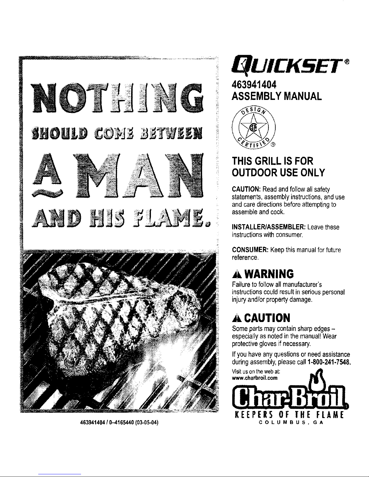
A
463941404/ 0-4165440(03-05-04)
463941404
ASSEMBLYMANUAL
THISGRILLISFOR
OUTDOORUSEONLY
CAUTION: Read and follow allsafety
statements, assemblyinstructions,and use
and care directionsbefore attemptingto
assemble and cook.
INSTALLER/ASSEMBLER:Leavethese
instructions withconsumer.
CONSUMER: Keepthis manualfor future
reference.
A WARNING
Failure to follow all manufacturer's
instructions couldresult in seriouspersonal
injuryand/or property damage.
A CAUTION
Some parts may containsharp edges-
especiallyas noted in themanual! Wear
protectivegloves if necessary.
Ifyou have any questionsor needassistance
during assembly, pleasecall 1-800-241-7548.
Visitusonthe.webat: ,,,.dllll
KEEPERS OF THE FLAME
COLUMBUS, GA
Page 2
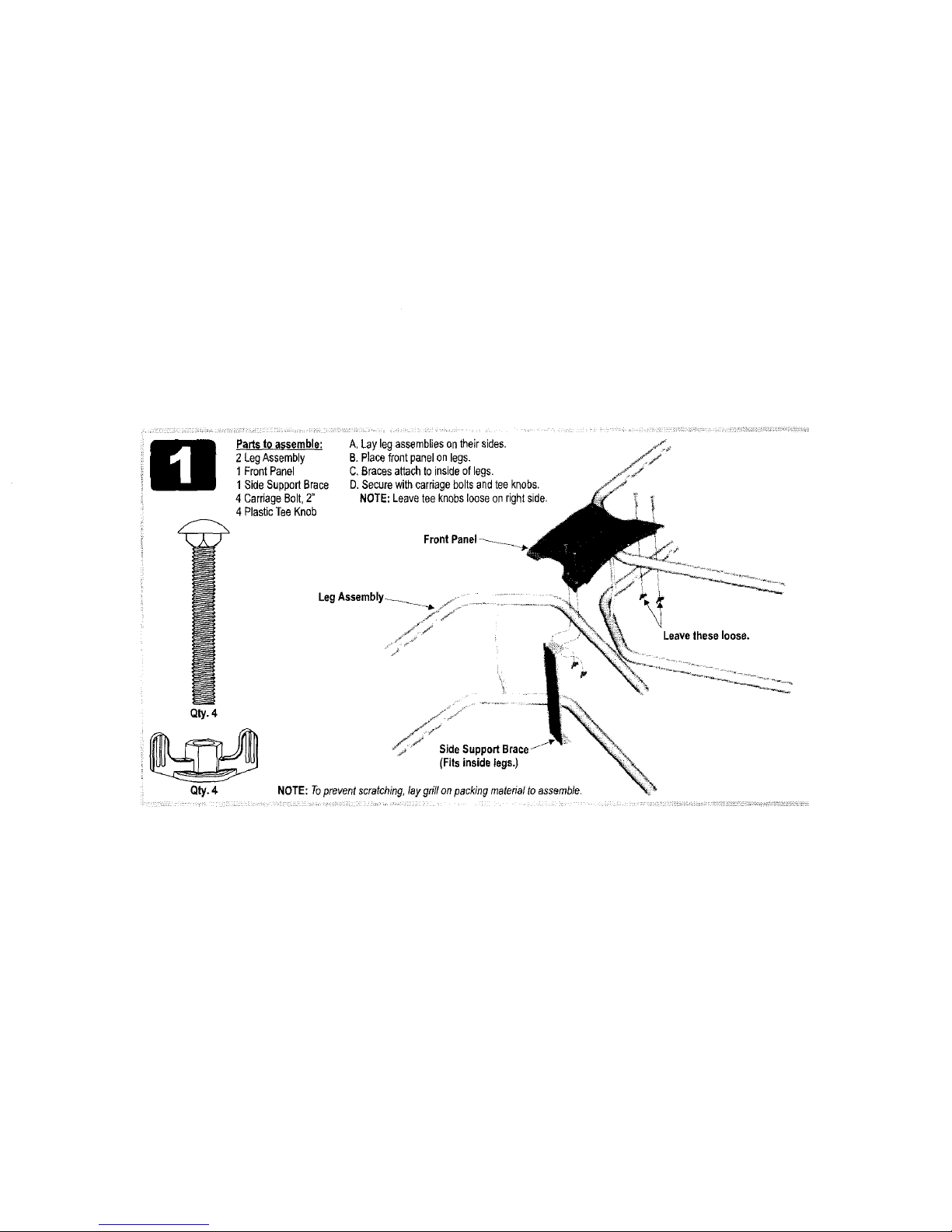
Partstoassemble:
2 LegAssembly
1FrontPanel
1SideSupportBrace
4 CarriageBolt,2"
4 PlasticTeeKnob
A,Lay legassembliesontheir sides.
B.Placefront panelonlegs.
C.Bracesattachto insideof legs.
D. Securewithcarriageboltsandteeknobs.
NOTE:Leaveteeknobslooseonrightside.
LegAssembly_._ ................
/ j"
, Leavetheseloose.
Qty.4
SideSupportBrace
(Fits insidelegs.)
Qty.4 NOTE:Topreventscratching,laygrillonpackingmaterialto assemble.
Page 3
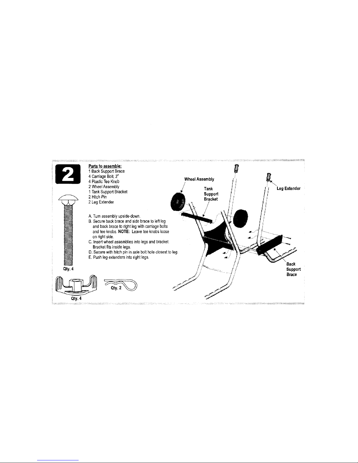
ParLsto assemble:
1 BackSupportBrace
4 CarriageBolt,2"
4 PlasticTeeKnob WheelAssembly
2 WheelAssembly Tank
1TankSupportBracket Support
2 HitchPin Bracket
2 LegExtender
Leg Extender
A.Turnassemblyupside-down.
B.Securebackbraceandside braceto leftleg
and backbraceto rightlegwithcarriagebolts
andteeknobs•NOTE: Leaveteeknobsloose
on dghtside.
C. Insertwheelassembliesinto legsandbracket•
Bracketfitsinsidelegs,
D. Securewithhitchpininaxle boltholeclosestto leg.
E,Pushlegextendersintorightlegs.
Qty.4
Qty.4
Back
Support
Brace
Page 4
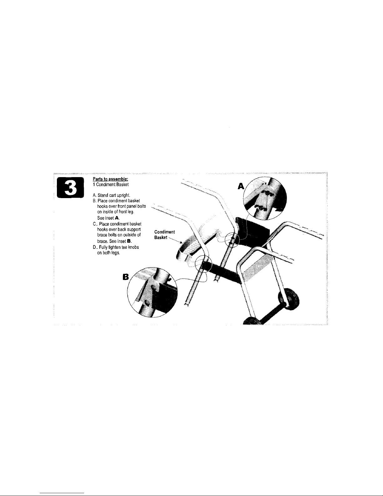
Partsto assemble:
1 CondimentBasket
A. Standcartupright.
B.Placecondimentbasket _\
hooksoverfrontpanelbolts o,,- ,_
on insideoffrontleg. _,_,._
SeeinsetA.
C..Placecondimentbasket _
hooksoverbacksupport Condiment
braceboltson outsideof
Basket
brace,SeeinsetB.
D..Fullytightentee knobs
on bothlegs.
B
A
Page 5
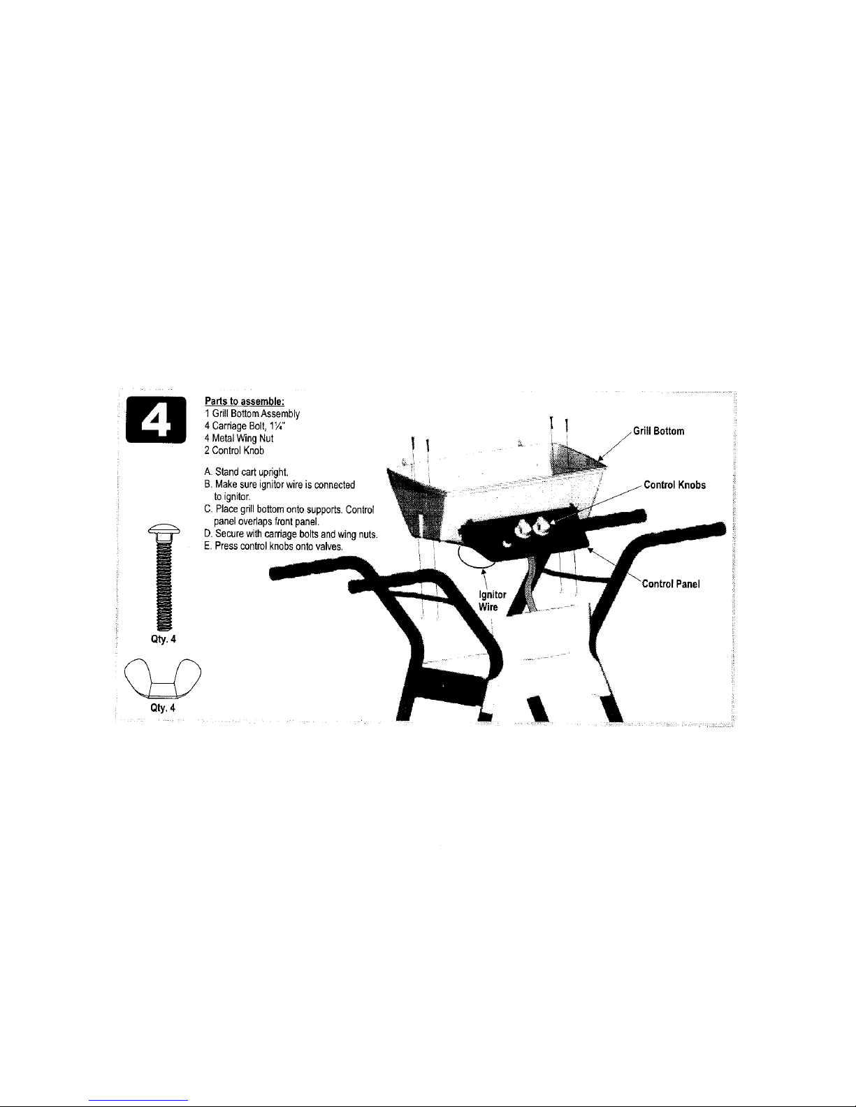
Qty.4
Partsto assemble:
1GrillBottomAssembly
4 CarriageBolt,1Y,"
4 MetalWingNut
2 ControlKnob
A. Standcartupright.
B.Makesureignitorwireis connected
to ignitor.
C. Placegrillbottomontosupports.Control
paneloverlapsfrontpanel.
D. Securewithcarriageboltsandwingnuts.
E. Presscontrolknobsontovalves.
: Qty.4
Ignitor
INire
el
Page 6

Partsto assemble:
1V-Bar
A.PlaceV barontosupportsat each
endofgrillbottom.
NOTE:
Ceramicbriquetsarenot required.
Page 7

Partsto assemble: A.Attachshelftorightsideusingfourwing screws
1 SideShelf or crownscrews.
4 WingScrewor B.Pushplasticendcapsinto leftlegassembly.
CrownScrew
--OR-- _
SideShelf
Qty.4 EndCap
Page 8

Partstoassemble;
1SideburnerBody
1SideburnerFrame
1CrownScrewor
WingScrew
1CarriageBolt,2"
1MetalWingNut
A.Placesideburnerbodyonto
legs.Insertcrownscreworwing
screwthroughleg,middleholein
toolholder,andinto body.
B.Inserttabonfrontof sidebumer
frameintobody,thenalignthe
rearframehole,rearbody hole,
and middlerearleghole.Secure
withcarriageboltand metalwing
[_ _ nut.
Qty.1 Qty.1 Qty.1
Sideburner\
Frame
Sideburner_
Body
Tabon
frameinto
holein _
body.
Page 9

Partsto assemble: Grate
1 Sidebumer
1SideburnerGrate
1SideburnerKnob
1 MetalWingNut
A. Insertsideburnertubeinto frame,placingthreadedstudon bottomof
burnerintosmallholeinframe.Attachfrombeneathwithmetalwingnut.
Donotfullytighten.
B.Insertsideburnervalve(attachedtovalvecup)intoburnertube,then
snapcupintosidebumerbody.Noteproperengagementin insetbelow.
C. Presssideburnerknobontovalvestem.
D.Afterensuring proper tubelvalveengagement,fullytightenburnerwingnut.
E.Placesideburnergrateontobody.
F.Locatethelongsideburnerignitorwire(attachedtoignitorbehindcontrol
panel).Routewireoversidesupportbraceand
attachto electrodeon bottomofsideburner,
Proper
tube-to-valve
engagement
Sidebumer
Knob
Sideburner_-_
IgnitorWire
ValveC_
Page 10

Partsto assemble: j_\
1 GrillLid _
1 Handle LogoPlate_//'_
1LogoPlate
2 MetalWingNut
2 HingePin
2 HitchPin
A.Attachlidtogrill bottomwith
hingeandhitchpins.
B.Attachhandletolidwithtwo
metalwingnuts.
C. Snaplogoplateintolid.
(Lidstylemayvary)
Qty.2
Qty.2
Page 11

Partsto assemble: rearofSwingAwaysshould
1 UpperSwingAway pointupward.
1LowerSwingAway
1CookingGrate _ UpperSwingAway
A. Sliderearpivotwireof lowerSwingAway
intolowerholesin sideofgrill lid.
B.Insertlegwiresintotop holeof
three-holepatternin sideof grill
bottom.
C. Sliderearpivotwireof upper
SwingAwayintomiddleholes
in sideof grilllid.
D. Insertlegwiresintoloopon
sidesoflowerwarmingrack.
E.Placecookinggrateontograte
restsin grillbottom.
slower SwingAway
Cooking
Grate
Page 12

Parts to assemble:
1TankRetainerWire
1 CarriageBolt,1¼"
1 PlasticTeeKnob
A.Attachretainerwireto side
bracewithcarriageboltand
tee knob.Leaveloose.
Page 13

Partsto assemble: LP tankis soldseparately.Filland
1LPGasTank leakcheckbeforeattachingtogrill
(Notincluded) andregulator.
A.CenterLPtankonsupportbracket
withcollaropeningtofront•
B.Slideretainerovertankcollarand
tightenteeknob,
/Tank Collar
CAUTION
Tankcollaropeningmustfacetofront ofcartonce
tankisattached.
Failuretoinstall tankcorrectlymayallowgashoseto
bedamagedinoperation,resultingintheriskoffire.
See Use & Care manualto perform the
"Burner Flame Check" and for important
safety instructions before using.
i
? ....
/
//
/
/
LPGasTank
/
/
Page 14

Partstoassemble:
1GreaseClip
A, Hanggreaseclip
beneathgrillbottom.
B.Hanganemptysoup
can(netincluded)from
greaseclip.
!11 1CAUTION l_-_lll
" "i!_]_rrietm°bn_a Imlcafnginl_IwiPt_Vir_ils_aUfSt_rhe°trgprea;er_
Rear view
of grill.
Page 15

PartsList- Model463941404
Kev Qtv, D_
Part#
A 1 Upper SwingAway .................... 4156450
B 1 Lower SwingAway .................... 4152000
C 1 Condiment Basket .................... 4154271
D 1 Side Shelf........................... 4154542
E 1 Handle ............................. 4154474
F 1 Sideburner Grate ..................... 4156376
G 2 WheelAssembly ...................... 4310002
H 1 Back Support Brace ................... 4500250
I 1 V-Bar .............................. 4500292
J 1 Sideburner Frame .................... 4501705
K 1 Tank Support Bracket.................. 4503122
L 2 Leg Assembly ........................ 4503286
M 1 Front Panel.......................... 4503116
N 1 Side Support Brace ................... 4503120
O 1 SideburnerBody ...................... 4310005
P 4 #10xl/2", T-20, Self-Tap Screw .......... 4080043
Q 2 Valve Clip ........................... 4151043
R 1 BurneflCollector Assembly .............. 4505085
S 1 Control Panel Assembly ................ 4530241
T 2 Control Knob ........................ 4154470
U 1 Grill Bottom.......................... 4580796
V 1 Grill Lid ............................. 4580105
W
X
Y 1
Z 1
AA 1
BB !
CC 2
1
1
1
Part#
1 Tank Retainer Wire.................... 4151018
1 Sidebumer Knob ..................... 4154471
Logo Plate .......................... 4157147
Sideburner .......................... 5068026
Grease Clip ......................... 5156607
Cooking Grate ....................... 4152742
Leg Extender ........................ 4154540
Hardware Sag, Cart ................... 4254079
Hardware Bag, Shelf .................. 4254050
Hardware Bag, Sideburner.............. 4254086
Optional Assembly Hardware
We realize some customersprefertousetools.Optional hex
nuts have been providedfor youto use.
Page 16

X
I
J
N
D
I
/
c s\
P
M
 Loading...