

Page 1
For Outdoor Use Only
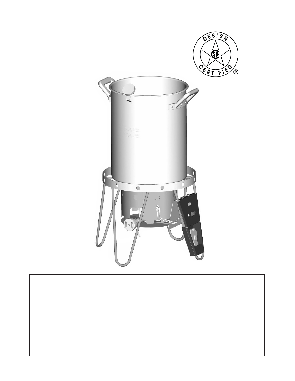
Turkey/Fish Fry Set
Assembly, Use and Care
04101424
To installer or person assembling this appliance: Leave this manual with
this appliance for future reference.
This instruction manual contains important information necessary for
the proper assembly and safe use of the appliance.
Read and follow all warnings and instructions before assembling and
using the appliance.
Follow all warnings and instructions when using the appliance.
Keep this manual for future reference.
Turkey/Fish Fry Set / 42804051 / (08-19-04)
Tools required:
Phillips screwdriver • Adjustable wrench
Page 2
2
DANGER
If you smell gas:
1. Shut off gas to the appliance.
2. Extinguish any open flame.
3. If odor continues, keep away from the appliance and immediately call
your Fire Department.
Failure to follow these instructions could result in fire or explosion which
could cause property damage, personal injury or death.
1. Never operate this appliance unattended.
2. Never operate this appliance within 10 feet or 3 m of any other gas
cylinder.
3. Never operate this appliance within 25 feet or 7.5 m of any flammable
liquid.
4. Do not fill cooking vessel beyond maximum fill line.
5. Never allow the oil/grease to get hotter than 400°F or 200°C. If the
temperature exceeds 400°F (200°C) or if oil begins to smoke, immediately
turn the burner or gas supply OFF.
6. Heated liquids remain at scalding temperatures long after the cooking
process. Never touch cooking appliance until liquids have cooled to
115°F or 45°C or less.
7. If a fire should occur keep away from the appliance and immediately call
your fire department. Do not attempt to extinguish an oil/grease fire with
water.
Failure to follow these instructions could result in fire or explosion which
could cause property damage, personal injury or death.
DANGER
Page 3

Safety Symbols
The symbols and boxes shown below explain what each heading means. Read and follow all of the
messages found throughout the manual.
DANGER
CAUTION
CAUTION: Indicates a potentially hazardous situation or usafe practice which, if not
avoided, may result in minor or moderate injury.
WARNING
WARNING: Indicates a potentially hazardous situation which, if not avoided, could
result in death or serious injury.
DANGER: Indicates an imminently hazardous situation which, if not avoided, will result
in death or serious injury.
3
WARNING
Combustion by-products produced when using this product contain chemicals known to
the State of California to cause cancer, birth defects, or other reproductive harm.
Page 4
WARNING
1. Never leave the appliance unattended. Keep children and pets away from the
appliance at all times.
2. The use of alcohol, prescription or non-prescription drugs may impair the
consumer’s ability to properly assemble or safely operate the appliance.
3. This appliance is for OUTDOOR use only. Do NOT use in a building, garage or
any other enclosed area. Do NOT use in or on a recreational vehicle or boat.
NEVER use this appliance as a heater.
4. When cooking, the appliance must be on a level, stable noncombustible
surface in an area clear of combustible material. An asphalt surface (blacktop)
may not be acceptable for this purpose.
5. Keep the fuel supply hose away from any heated surfaces.
6. When cooking with oil or grease, the thermometer provided MUST be used.
Follow instructions in this manual for proper installation and use of the
thermometer. If the thermometer supplied with this appliance has been lost or
damaged, a replacement thermometer meeting or exceeding the appliance
manufacturer specifications shall be obtained before using the appliance.
7. If the temperature exceeds 400°F (200°C) or if oil begins to smoke, immediately
turn the burner or gas supply OFF and wait for the temperature to decrease to
less than 350°F (175°C) before relighting burner according to the
manufacturer’s instructions. If there is a lid (cover), do not remove the lid.
8. In the event of an oil/grease fire immediately call the fire department. Do not
attempt to extinguish with water. When cooking with oil/grease, have a Type
BC or ABC fire extinguisher readily available. A Type BC or ABC fire
extinguisher may, in some circumstances, contain the fire.
9. Never overfill the cooking vessel with oil, grease or water. Follow instructions
in this manual for establishing proper oil, grease or water levels.
10. Introduction of water or ice from any source into the oil/grease may cause
overflow and severe burns from hot oil and water splatter. When cooking with
oil/grease, all food products MUST be completely thawed and towel dried
before being immersed in the cooking vessel.
11. Do not place empty cooking vessel on the appliance while in operation. Use
caution when placing anything in cooking vessel while the appliance is in
operation.
12. In the event of rain, snow, hail, sleet or other forms of precipitation while
cooking with oil/grease, cover the cooking vessel immediately and turn off the
appliance burners and gas supply. Do not attempt to move the appliance or
cooking vessel.
13. Do not move the appliance when in use. Allow the cooking vessel to cool to
115 before moving or storing.°F (45°C)
4
Page 5
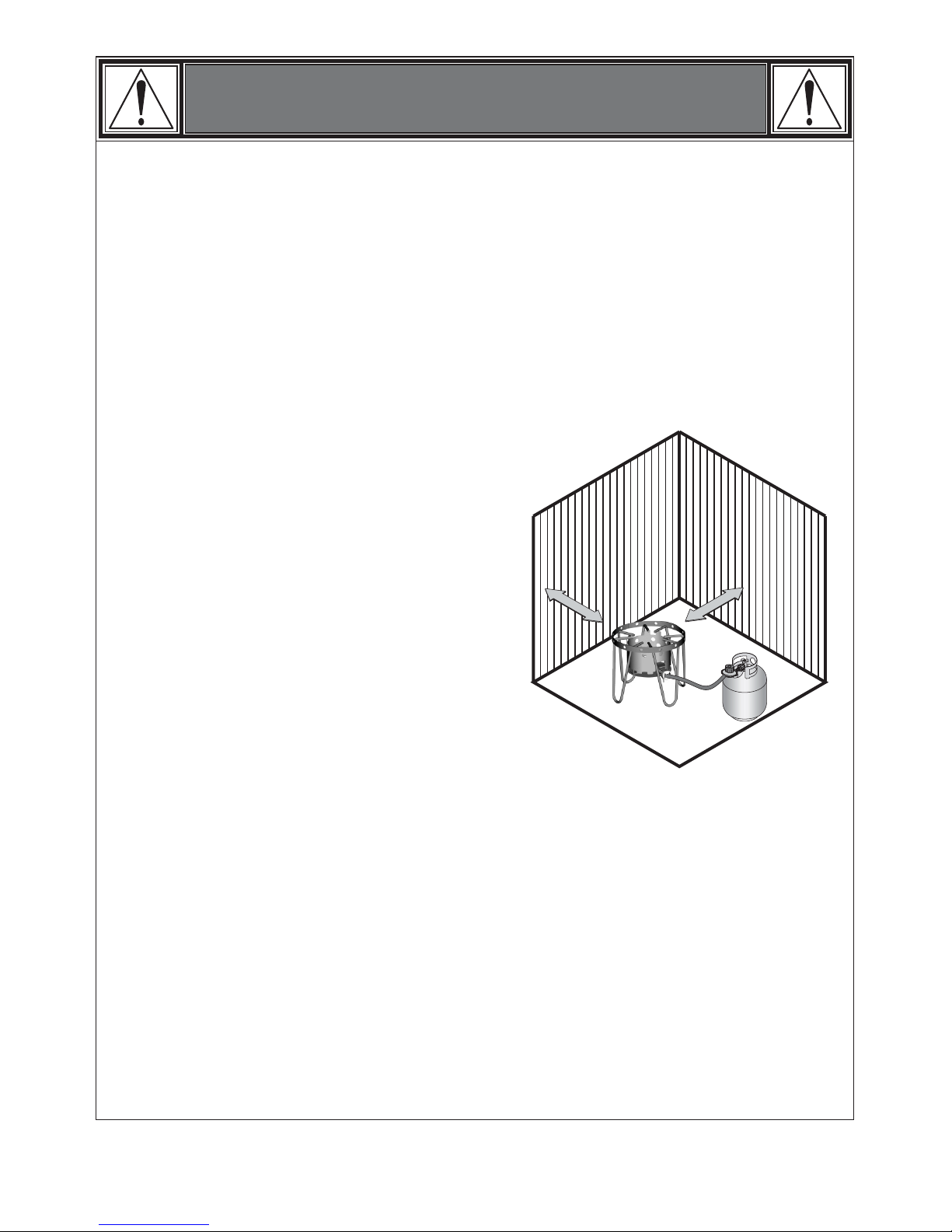
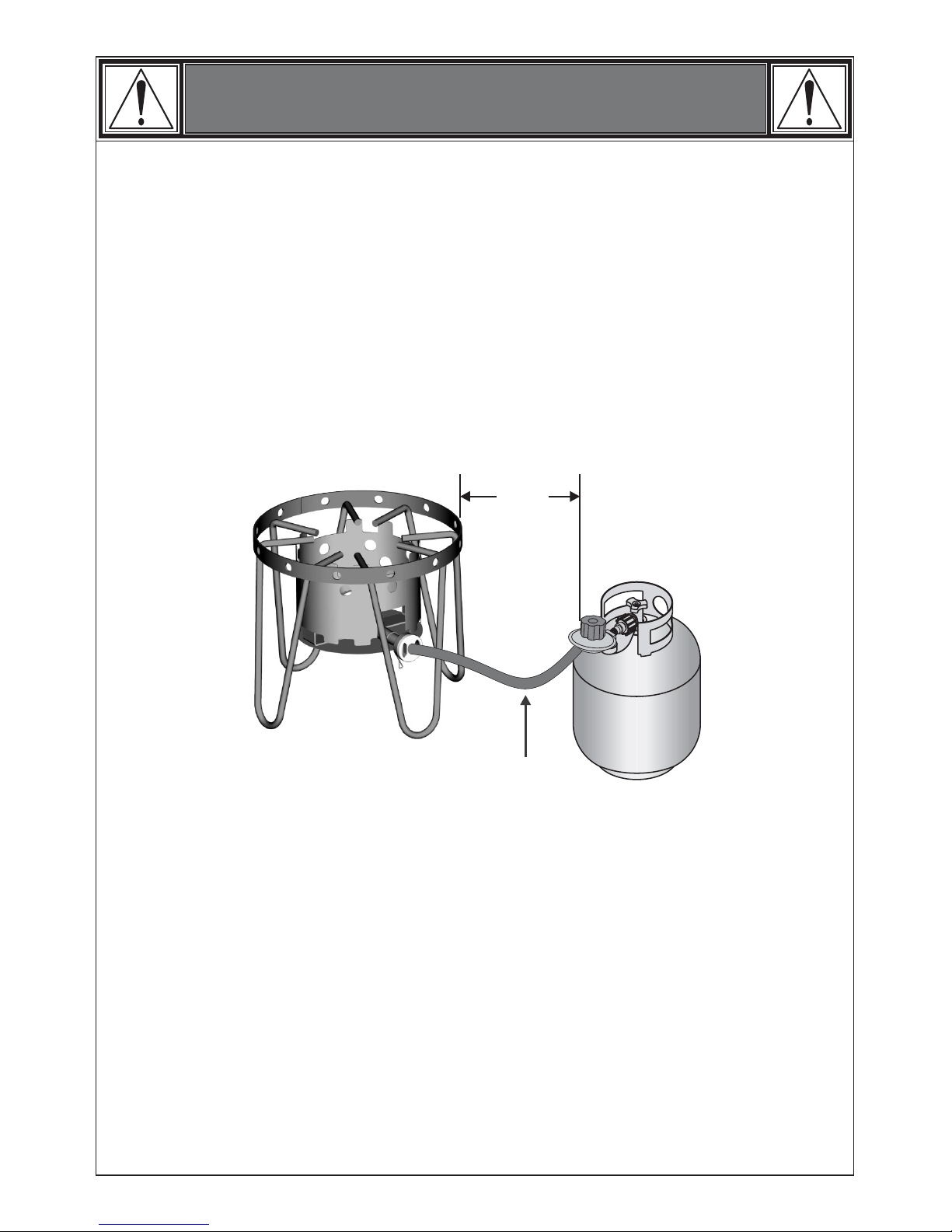
• Use appliance at least 10 ft. from any wall or
surface. Maintain 10 ft. clearance to objects
that can catch fire or sources of ignition such
as pilot lights on water heaters, live electrical
appliances, etc. Never use under balconies
made of wood or ANY overhead
construction.
• Apartment Dwellers: Check with
management to learn the requirements and
fire codes for using an LP Gas appliance at
an apartment. If allowed, use outside on the
ground floor with a ten (10) foot clearance
from walls or rails.
• Before opening LP tank valve, check the coupling nut for tightness. When appliance is
not in use, turn off control knob and LP tank valve.
• Never move appliance while in operation or still hot.
• If you notice grease or other hot material dripping from appliance onto valve, hose or
regulator turn off gas supply at once. Determine the cause, correct, clean and inspect
valve, hose and regulator before continuing. Perform a leak test.
• The regulator may make a humming or whistling noise during operation. This will not
affect safety or use of appliance.
• Clean and inspect the hose before each use of the appliance. If there is evidence of
abrasion, wear, cuts or leaks, the hose must be replaced prior to the appliance being
put into operation.
WARNING
Installation Safety Precautions
• Use appliance only with LP (propane) gas and the regulator/valve assembly supplied.
• Installation must conform with local codes, or in their absence with National Fuel Gas
Code, NFPA 54/ANSI Z223.1. Handling and storage of LP cylinders must conform to
LP Gas Code NFPA/ANSI 58. Appliance is not for use in or on recreational vehicles or
boats.
• This appliance is safety certified for use in the United States only. Do not modify for use
in any other location. Modifications will result in a safety hazard.
• This appliance shall be used only outdoors and shall not be used in a building, garage
or any other enclosed area.
5
Page 6
• Never use a cooking vessel larger than 30 qts. and taller than 15½ inches.
• Never fill pot above upper fill line. Oil can splatter causing staining or discoloration to
ground surface.
• Never leave the appliance unattended. Keep children and pets away from the
appliance at all times.
• Never place empty cooking vessel on the appliance while in operation. Use caution
when placing anything in the cooking vessel while the appliance is in operation.
• Never move the appliance when in use. Allow the cooking vessel to cool before moving
or storing.
• This appliance is not intended for and should never be used as a heater.
• Never operate appliance with LP tanks out of correct position specified in assembly
instructions.
• Always close LP tank valve and remove coupling nut before moving LP tank from
specified operating position.
• Appliance shall not be used for commercial cooking.
• This appliance will be hot during and after use. Use insulated oven mitts or gloves for
protection from hot surfaces or cooking liquids.
• Avoid bumping of or impact with the appliance to prevent spillage or splashing of hot
cooking liquid.
• Never drop food or accessories into hot cooking liquid. Lower food and accessories
slowly into the cooking liquid in order to prevent splashing or overflow. When removing
food from the appliance care should be taken to avoid burns from hot cooking liquids.
24”
WARNING
6
WARNING: Hose is a trip hazard.
Page 7
DANGER
• The safety relief valve on the LP tank could activate releasing gas and cause an
intense fire with risk of death or serious injury. Therefore, follow instructions bulleted
below exactly.
• NEVER store a spare LP tank under or near appliance or in enclosed areas.
• NEVER fill the cylinder beyond 80% full. An overfilled spare LP tank is hazardous
due to the possible gas released from the safety relief valve.
• If you see, smell, or hear escaping gas, immediately get away from the LP
tank/appliance and call your fire department.
• All spare LP tanks must have safety caps installed on the LP tank outlet.
LP Tank Removal, Transport and Storage
LP Tank
The LP tank used with your appliance must meet the following requirements:
• Turn OFF all control knobs and LP tank valve. Turn coupling nut counterclockwise by
hand only — do not use tools to disconnect. Install safety cap onto LP tank valve. Always
use cap and strap supplied with valve. Failure to use safety cap as directed may result in
serious personal injury and/or property damage.
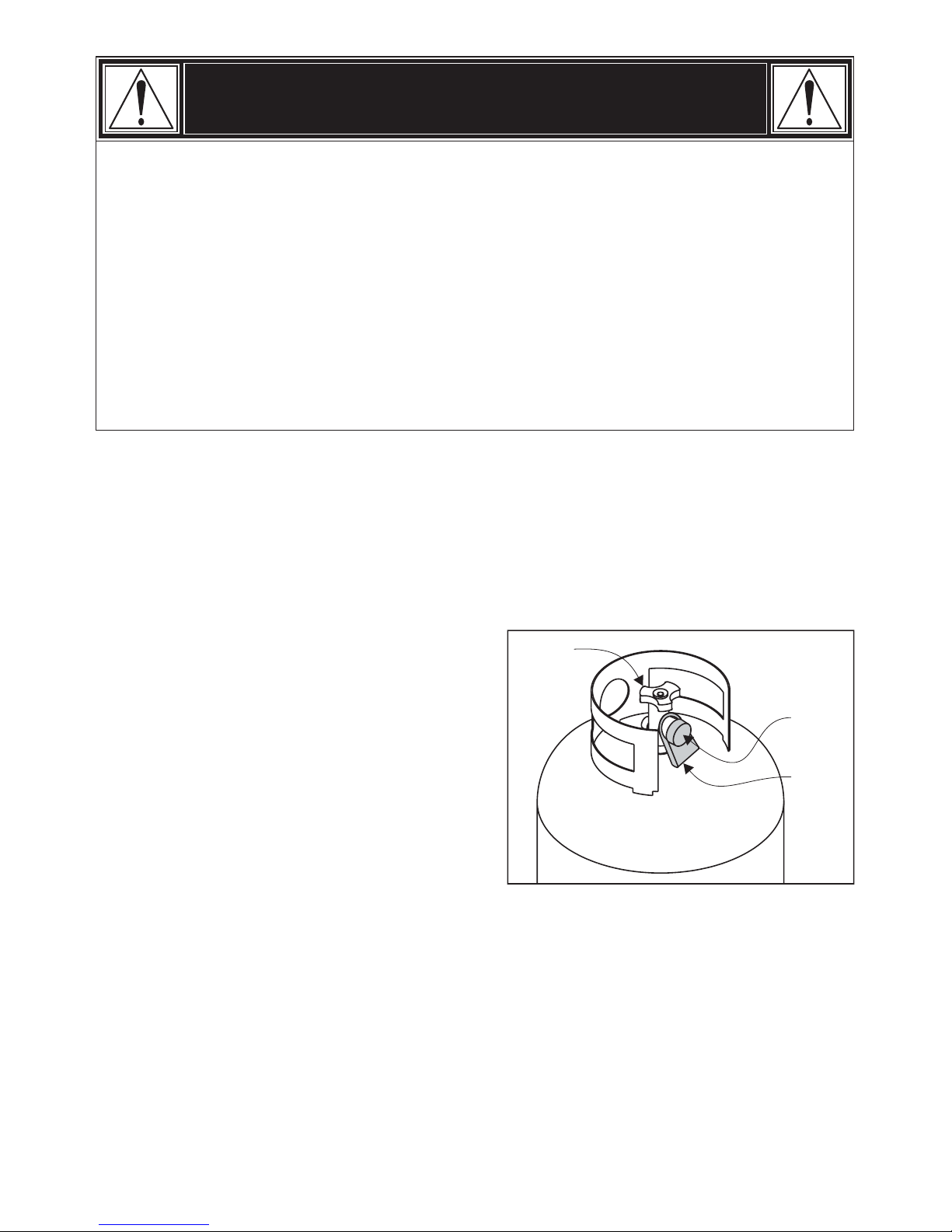
• A disconnected LP tank in storage or being
transported must have a safety cap installed
(as shown). Do not store an LP tank in
enclosed spaces such as a carport, garage,
porch, covered patio or other building. Never
leave an LP tank inside a vehicle which may
become overheated by the sun.
• Do not store LP tanks in an area where
children play.
• Purchase LP tanks only with these required measurements: 12” (30.5cm) (diameter) x 18”
(45.7cm) (tall) with 20 lb. (9 kg.) Capacity maximum.
• The LP tank must be constructed and marked in accordance with specifications for LP
tank of the U.S. Department of Transportation (DOT). See LP tank collar for marking.
LP Tank
Valve
Safety
Cap
Retainer
Strap
7
Page 8

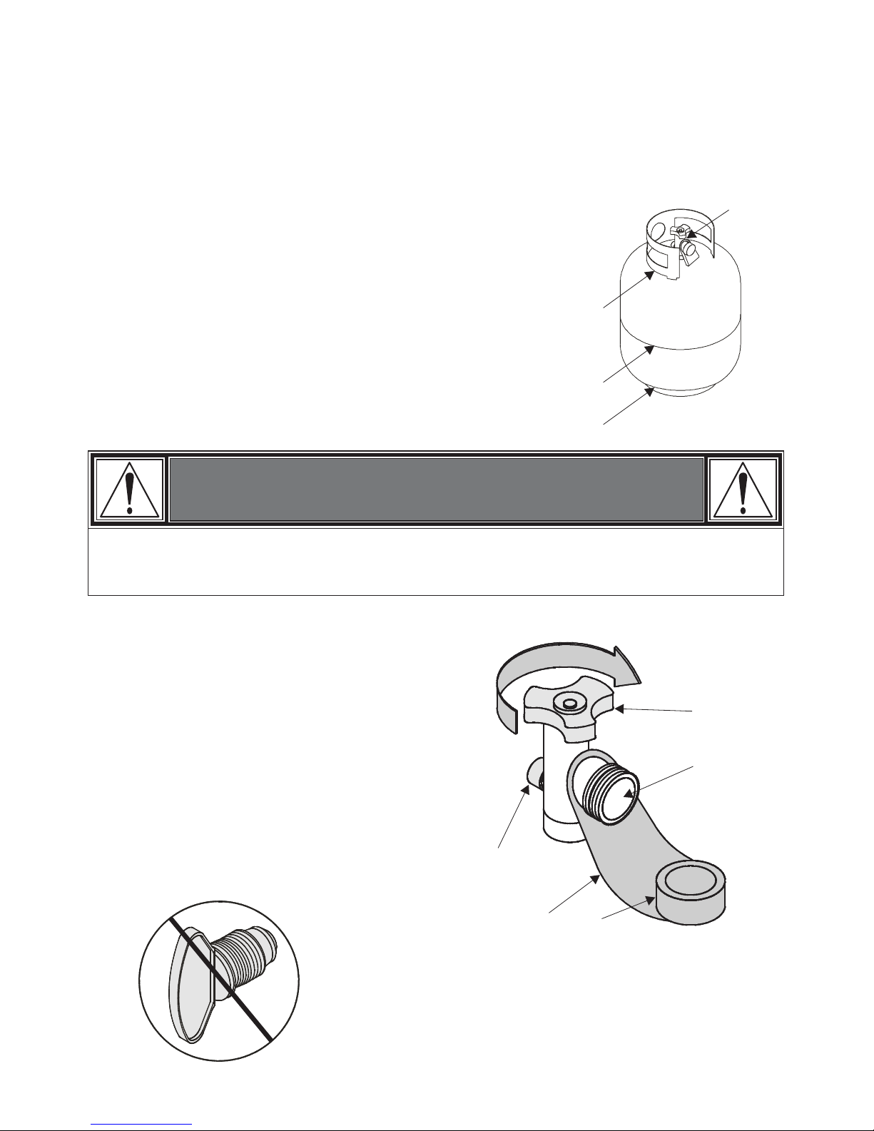
LP tank valve must have:
LP (Liquefied Petroleum Gas)
LP Tank Filling
LP Tank Exchange
• Type 1 outlet compatible with regulator or appliance.
• Safety relief valve.
• UL listed Overfill Protection Device (OPD). This OPD
safety feature is identified by a unique triangular hand
wheel. Use only tanks equipped with this type of valve.
LP tank must be arranged for vapor withdrawal and
include collar to protect LP tank valve.
• LP gas is non toxic, odorless and colorless when produced. For Your Safety, LP gas has
been given an odor (similar to rotten cabbage) so that it can be smelled.
• LP gas is highly flammable and may ignite unexpectedly when mixed with air.
• Use only licensed and experienced dealers.
• LP dealer must purge tanks before filling.
• Dealer should NEVER fill LP tank more than 80% of LP tank volume. Volume of propane
in tanks will vary by temperature.
• A frosty regulator indicates gas overfill. Immediately close LP tank valve and call local LP
gas dealer for assistance.
• Do not release liquid propane (LP) gas into the atmosphere. This is a hazardous practice.
• To remove gas from LP tank, contact an LP dealer or call a local fire department for
assistance. Check the telephone directory under “Gas Companies” for nearest certified
LP dealers.
• Many retailers that sell appliances offer you the option of replacing your empty LP tanks
through an exchange service. Use only those reputable exchange companies that
inspect, precision fill, test and certify their cylinders. Exchange your tank only for an OPD
safety feature-equipped tank as described in the “LP Tank” section of this manual.
• Always keep new and exchanged LP tanks in upright position during use, transit or
storage.
• Leak test new and exchanged LP tanks BEFORE connecting to appliance.
OPD Hand Wheel
8
Page 9
LP Tank Leak Test
For your safety
Use mild soap and water. Do not use household
cleaning agents.
• Leak test must be repeated each time LP tank is exchanged or refilled.
• Do not smoke during leak test.
• Do not use an open flame to check for gas leaks.
• Appliance must be leak checked outdoors in well-ventilated
area, away from ignition sources such as gas fired or
electrical appliances. During leak test, keep appliance away
from open flames or sparks.
Use a clean paint brush and 50/50 soap and water solution.
Damage to gas train components can result.
Brush soapy solution onto all weld seams and entire valve area.
WARNING
If “growing” bubbles appear, do not use or move the LP tank. Contact an LP gas supplier
or your fire department.
Connecting Regulator to the LP Tank
full stop.
1. Place LP tank on a secure, level,
and stable surface.
2. Turn control knob to the OFF position.
3. Turn LP tank OFF by turning hand wheel
clockwise to a
4. Remove the protective cap from the LP tank
valve. Always use cap and strap supplied
with valve.
Do not use a POL transport plug (A) (plastic part with
external threads)! It will defeat the safety feature of the valve.
A
Off Clockwise
OPD Hand
Wheel
Type 1 outlet
with thread
on outside.
Safety Relief
Valve
Strap and cap
9
Page 10
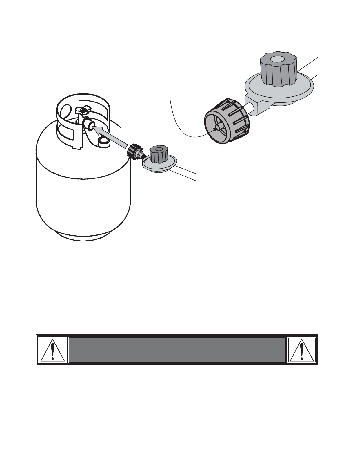
5. Hold regulator, insert nipple (B) into LP tank valve. Hand tighten coupling nut, holding
regulator in a straight line (C) with LP tank valve so as not to cross thread the
connection.
6. Turn the coupling nut clockwise to tighten to a full solid stop. The regulator will seal on
the back-check feature in the LP tank valve, resulting in some resistance. An additional
one-half to three quarters turn is required to complete connection. Tighten by hand only
— do not use tools.
NOTE: If you cannot complete connection, disconnect regulator and repeat steps 5 and 6.
If you are still unable to complete the connection, do not use this regulator!
WARNING
• Do not insert any tool or foreign object into the valve outlet or safety relief valve. You
may damage the valve and cause a leak. Leaking propane may result in explosion, fire,
severe personal injury, or death.
• Never attempt to attach this appliance to the self-contained LP gas system of a camper
or trailer or motor home.
Hold coupling nut and regulator as shown
for proper connection to LP tank valve.
Nipple must be centered
into the LP tank valve.
B
C
Straight
10
Page 11

Leak Testing Valves, Hoses and Regulator
1. Turn all control knob(s) to OFF.
2. Be sure regulator is tightly connected to LP tank.
3. Completely open LP tank valve by turning
hand wheel counterclockwise. If you hear
a rushing sound, turn gas off immediately.
There is a major leak at the connection.
Correct before proceeding.
4. Brush soapy solution onto indicated
connections shown at right in and .
5. If “growing” bubbles appear, there is a leak.
Close LP tank valve immediately and retighten
connections. If leaks cannot be stopped, do not
try to repair. Call for replacement parts. Order
new parts by giving the serial number, model
number and name of items needed to the
Warranty Service Center at 1-800-232-3398.
Use only replacement parts specified by
manufacturer.
6. Always close LP tank valve after performing tank leak test by turning hand wheel
clockwise.
AB
(Reference connection of hose to burner
on page 15.)
WARNING
• Do not use appliance until leak checked.
• If leak is detected at any time, .
• If you cannot stop a gas leak, immediately close LP tank valve, leave area of
appliance, and call LP gas supplier or your fire department!
STOP
11
A
B
WARNING
• This device is equipped with a remote electronic ignition system that can become
inadvertently activated by another electronic device, causing a spark.
• Do not store in an area where flammable fumes can accumulate and ignite.
Page 12

CAUTION
If burner does not light OR if burner flame is accidentally extinguished, turn knob to OFF,
wait 5 minutes, try again. If the burner does not ignite with valve open OR if burner flame
is accidentally extinguished after lighting, gas will continue to flow out of the burner and
could accidentally ignite with risk of injury.
Burner Flame Check
• Light burner, rotate knob from HIGH to LOW. You
should see a smaller flame in LOW position than
seen on HIGH. Always check flame prior to each
use. The air damper (D) mounted on the back of
your burner helps to control the amount of
primary air that mixes with the LP gas. A blue
flame with little or no yellow flame provides the
best heat. Adjust the air damper by turning it
clockwise or counterclockwise until the desired
flame is achieved.
Holes in Burner
Good
Bad
Yellow
Blue
Yellow
Blue
D
Air Damper
12
Lighting Instructions
Do not lean over LP cooker while lighting.
1. Turn regulator control valve to OFF
position.
2. Fully open LP tank valve.
3. Slowly turn ON the regulator control
valve. Push transmitter button or button
on receiver. If ignition does not occur,
light a match and place it over burner.
Slowly turn ON regulator control valve.
DO NOT stand with head or arms over
cooker.
4. If ignition does not occur in 5 seconds,
turn the burner control(s) off, wait 5
minutes, and repeat the lighting
Procedure. Curing of paints and parts
will produce an odor only on first use.
Ignitor Button
Turning LP Cooker Off
• Turn all knobs to OFF position. Turn LP tank
OFF by turning hand-wheel clockwise to a full stop.
Page 13

WARNING
Spiders’ nests or wasps’ mud inside the burner may cause fire at the air damper. If a fire
occurs, turn off gas supply at LP tank valve. (See representative illustration
in Fig. 1)
immediately
Cleaning the Burner
NOTE:
Spiders and small insects can spin webs and build nests inside the burner. This especially
occurs in late summer and fall before frost when spiders are most active. These nests can
obstruct gas flow and cause a fire in and around the burner and orifice. Such a fire can
cause operator injury and serious damage to the appliance.
To help prevent a blockage and ensure full heat output, clean and inspect burner tube often
(once or twice a month). NOTE: Water or air pressure will normally clear a spider web,not
Steps for Cleaning the Burner:
1. Remove orifice/hose from the burner.
2. Look inside the burner tube for nests,
webs, or mud.
3. To remove the above obstructions, use
an accessory flexible venturi brush or
bend a small hook on one end of a
long flexible wire such as the one
shown in Fig. 2.
4. Inspect and clean the burner if needed.
5. Reattach orifice/hose to burner.
13
Hose Check
•Before each use, check to see if hoses are cut or worn. Replace damaged hose assembly
before using appliance. Use only valve/hose/regulator specified by manufacturer.
Page 14

Cleaning and Maintenance
CAUTION
All cleaning and maintenance should only be done when the appliance is cool and with
the fuel supply turned off at the LP tank. DO NOT clean any part in a self-cleaning oven.
The extreme heat will damage the finish.
Correct care and maintenance will keep your appliance operating smoothly. Clean regularly
as determined by the amount of use. NOTE: Clean the entire appliance each year and
tighten all hardware on a regular basis (1–2 times a year or more depending on usage).
Cleaning should be done where detergents won’t harm patio, lawn or the like.
• Mild dish washing liquid detergent • Hot water
• Wire brush • Paper clip
• Nylon cleaning pad • Soft brass bristled brush
• Wire brush loose corrosion from burner exterior. Clean clogged gas port holes
with an opened paper clip. Replace corroded or damaged burners that would emit excess
gas.
• Clean the cooking surface with soapy water and a
nylon cleaning pad.
Suggested Cleaning Materials:
Component Cleaning:
Burner:
Cooking surfaces, pots and pans:
14
• Keep appliance area clear and free from materials that burn.
• Do not block holes in bottom or sides of appliance.
• Check burner flames regularly.
• Use appliance only in well-ventilated space. NEVER use in enclosed space such as
carport, garage, porch, covered patio, or under ANY overhead construction.
• Completely thaw meat and poultry prior to placing in hot oil.
• To minimize splattering, dry surfaces of meat and poultry prior to placing in hot oil.
• When LP tank is connected to appliance, store outdoors in well-ventilated space and out
of reach of children.
• Store appliance indoors ONLY if LP tank is turned off and disconnected, removed from
appliance and stored outdoors.
Page 15

15
Burner
Alignment
Pin
Threaded
Pin
Heat Shield
Nut
Assembly Instructions
1. Insert the burner into the cooker stand and
through the cut-out opening in the side of the
stand.
2. Insert the threaded pin on the bottom of the
burner into the center hole in the burner bracket.
Make sure the alignment pin is seated in the
notch on the edge of the burner bracket.
3. Place the heat shield beneath the burner bracket,
aligned with the burner pins, and secure with the
#10-24 hex nut (keps).
4. Place the damper over the end of the burner.
Insert the brass hose fitting into the small end of
the spring, then thread brass fitting into the burner
and tighten. Be sure not to strip threads on brass
fitting. DO NOT OVERTIGHTEN. Proper
connection is critical for correct operation of unit.
Damper
Spring
Hose
Page 16

5. Thread wire hook through hole on side of
regulator.
6. When transporting or storing LP cooker without
tank attached, hook regulator onto burner or
cooker stand to prevent damage to regulator.
16
8. Remove four screws from back of module.
Back of module.
Front of module.
MODULE BATTERY INSTALLATION.
(Batteries not included.)
7. Locate Electronic Receiver Module.
Page 17

Electrode/Ignitor Assembly Instructions
Ground wire terminal must be
between electrode flange and wall of stand.
NOTE: Tip of electrode wire should be 1/16”-1/8”
from burner for proper ignition. Bend
electrode wire slightly if necessary.
10. Insert the electrode into the side of the cooker
stand, behind the ignitor panel. Secure the electrode
and the Ground wire to the stand with one #10x1/2”
self-tap screw.
The
end of the electrode wire should be above the edge
of the burner.
Electrode wire
Burner
Electrode
Ignitor
panel
Ground wire
17
9. Place module on flat
surface and remove
front cover. Insert two
AAA batteries and
reassemble front
ensuring that the rubber
gasket remains in place.
Secure with four screws
removed in step 2 .
+
+
-
-
(2 AAA)
Make sure rubber gasket remains in place.
CAUTION
A jumper wire is attached to receiver terminals to prevent shock during battery
installation and receiver attachment to stand. Do not remove jumper wire until
step 11 is completed.
Electrode flange
Ground wire
terminal
Page 18

12. Place the ignitor cover over the ignitor and
attach to ignitor panel using two #10x1/2” self-tap
screws.
Ignitor cover
18
11. Attach ignitor module to ignitor panel using two
#8x1/2” self-tap screws. Ignitor Button must be
CAREFULLY pulled through hole in Ignitor panel
before fully tightening the screws.
Remove and discard jumper wire on terminals.
Keep discarded wire away from small children.
Ignitor
panel
Ignition Module
Ignitor
Button
13.
Attach heat shield to ignitor cover
Using
The ignitor wire has a
connector at one end and a
connector at the other end. Push
the round connector into the
ignitor through the lower left hole
in the ignitor cover. Push the flat
connector onto the electrode tab.
Connect ground wire to right
terminal.
flat
round
two #10x1/2” self-tap
screws.
Ignitor wire
Ground wire
Flat end
Left terminal
Heat
Shield
Heat shield screws
Page 19

19
TRANSMITTER BATTERY INSTALLATION (Batteries not included).
+
+
-
-
(2 AAA)
Using Your Thermometer
Check the thermometer before each use
212°F +/– 20°F
by
inserting into a pot of boiling water and ensuring that
it registers approximately (100°C
+/– 10°C). If it does not function properly, obtain a
replacement that meets or exceeds the
manufacturer’s specifications before using the
appliance.
Prior to lighting, position thermometer clip so that at
least 1/2” of thermometer tip is submerged in oil.
Reposition thermometer as necessary to cook.
Continue to use thermometer until burner is turned
off.
Use a small screwdriver or paperclip to open battery door.
Page 20

Receiver Box
3"
3"
10’.
7’
Inside this area remote ignitor may inadvertently be started by T.V. Remotes, garage door
openers, remote controlled toys, remote car alarms, etc. Keep children and pets away from
the appliance at all times.
WARNING
20
Page 21

21
LOCATION MATTERS
Select a safe place to fry your turkey. It should be in an open area, outside, and on a
cement or brick surface. Place the liquid propane gas tank and fryer so that any wind blows
the heat of the fryer away from the gas tank. Never use your fryer in an enclosed area, near
a wall or on a wooden deck. Keep a minimum clearance of 10 feet from the sides, front and
back of the fryer to any construction.
The following safety measures are recommended when using
your fry set.
PREPARE PROPERLY
• Remove and discard any
thermometer buttons, leg holders and
giblet packs contained inside the
completely thawed turkey. Do not
attempt to fry a frozen or partially
frozen turkey. Ensure your turkey is
completely thawed prior to
proceeding. The USDA recommends
thawing 24 hours (1 day) for every 4-5
pounds in a refrigerator.
• Insert the stainless steel turkey lifter
up through the cavity so that the legs
are at the top.
Page 22

22
Determining the maximum fill level
when using a pot without a maximum
fill line:
• Place the turkey (or other food
product) on the lifter.
• Place the turkey and lifter into the
empty pot.
• Fill the pot with water just until the
turkey is completely submerged.
There must be a minimum of 3 inches
or 8 cm between the water level and
top of the pot.
• Remove the turkey from the pot and
either mark the water level on the side
of the pot or measure the amount of
water in the pot.
• Remove the water and completely dry
the pot and the turkey.
• This is the amount of peanut oil the
pot is to be filled with to cook the
turkey.
• Use marinade by injecting it into the
thicker areas of the turkey breasts
and thighs.
• To use, load the injector with
marinade and insert the needle into
the turkey. Withdraw the needle
slowly while pushing the plunger,
minimizing large pockets of marinade
and spreading it more evenly. Discard
any unused marinade.
Page 23

23
• Completely pat dry the inside and
outside surfaces of the turkey. This is
very important as it reduces the
splattering of oil. After patting the bird
dry, add herb rubs or seasonings to
the skin.
FRY WITH CARE
• Check your hose at both ends for
proper connection. Also, place the
tank and hose so that they are not
located directly next to the fryer (see
photo). Center the pot over the burner
on the cooker.
• Fill the pot to the mark with peanut oil.
Remove the butcher’s tape from the
pot.
DANGER
• Do not fill past the maximum fill line
marked on the utensil.
• An oil overflow may occur resulting in
a fire which could cause property
damage, personal injury or death.
Follow directions above to prevent
this.
Page 24

24
• Light the burner unit and heat the oil
to 325° F.
.
• Check the oil using a deep fry
temperature gauge. If it has reached
325° F, you are ready to start deep
frying. Monitor the temperature
throughout the frying process to
maintain 325° F — never let the oil
temperature get hotter than 325° F.
• If the oil exceeds 400° F or if the oil
begins to smoke, immediately turn the
burner off.
Never leave the fryer
unattended at any time
• Wear long, insulated, flame-retardant
gloves to protect your hands and
arms. Use the lift handle to slowly
lower the turkey into the oil. Pause at
several points before reaching the
bottom of the pot.
• Adjust the burner to maintain 325° F.
Monitor the fryer during the entire
process to assure a safe frying
experience.
• Cook until a golden brown color is
achieved. Normal cooking time is 3½
minutes per pound.
Do not leave fryer
unattended.
Page 25

25
• Remove the turkey from the oil and
place it on paper towels in an
aluminum pan.
• Using a meat thermometer, check for
an internal meat temperature of
180° F.
• Remove turkey fry accessory and
allow the turkey to “rest” for 15
minutes to allow the juices to settle
into the turkey. Slice and serve!
Limited Warranty
Manufacturer warrants this Fry Set for replacement or repair of parts and/or workmanship for a period of 3
months. Paint is not warranted and may require touch-up. Items considered to be consumable such as batteries
are not covered under these warranties.
These limited warranties are made exclusively to the original consumer presenting proof of purchase. These
warranties are limited to non-commercial residential use only. Any returned goods must be shipped prepaid.
These warranties do not cover normal wear and tear or damages resulting from abuse or misuse. This warranty
excludes incidental or consequential cost due to damages or losses to persons or property of any nature.
NOTICE: Some states do not allow the exclusion or limitation of incidental or consequential damages or
limitations on how long an implied warranty lasts, so the above limitations or exclusions may not apply to you.
This warranty gives you specific legal rights and you may also have other legal rights which may vary from state
to state.
For further information or replacement parts, contact manufacturer, toll free at 1 (800) 232-3398.
Page 26

Please register your grill online at:
(If you register online, you do not need to send in this registration card.)
WWW.GRILLREGISTRATION.COM
26
Page 27

27
Page 28

Troubleshooting • Electronic Ignition System
Problem
No spark
using
transmitter.
No spark
using
Receiver
Module.
Possible Cause
• Push button on receiver.
• Transmitter out of range.
• Receiver window blocked.
• Electrode not in correct position.
• Loose electrode wire.
• Batteries installed incorrectly.
• Dead batteries.
• Faulty transmitter.
• Transmitter out of range.
• Receiver window blocked.
• Electrode not in correct position.
• Loose electrode wire.
• Batteries installed incorrectly.
• Dead batteries.
• Faulty Module.
Solution
• If electrode sparks, troubleshoot
transmitter. If electrode does not spark,
troubleshoot receiver.
• Reposition transmitter.
• Check for obstructions between
transmitter and receiver.
• Make sure electrode is within
of burner without touching burner.
• Make sure electrode wire secured tightly
to electrode.
• Make sure that the batteries
Are installed
Correctly.
• Replace
batteries.
• Replace
Transmitter.
• Reposition transmitter.
• Check for obstructions between
transmitter and receiver.
• Make sure electrode is within 1/4” of
burner without touching burner.
• Make sure electrode wire secured tightly
to electrode.
• Make sure that the batteries are
installed correctly.
• Replace batteries.
• Replace transmitter.
1/16”-1/8”
28
Page 29

PARTS LIST
ITEM
DESCRIPTION
QTY
55700394 BURNER KIT
1
55700460 SPRING & VENT KIT
1
42000028 HARDWARE BAG
1
55700577 ELECTRONIC RECEIVER/IGNITION KIT
1
55700578 ELECTRODE KIT
1
55700579 ELECTRONIC RECEIVER MOUNTING KIT
1
55700580
ELECTRONIC RECEIVER HEAT SHIELD KIT
1
40011308 OUTER CARTON, 04101424
1
55700403
30 QT ANODIZED POT W/POUR SPOUT AND 12” GLASS LID
1
33200089 COOKER STAND 3/8” WIRE
1
41201241 STAINLESS STEEL TURKEY FRY T-STAR
1
41201242 STAINLESS STEEL T-STAR LIFTING HANDLE
1
29100560 ELECTRONIC TRANSMITTER ASSEMBLY
1
43302827 HEAT SHIELD
1
41213000
HVR ASSEMBLY
1
41201236 LONG STEM THERMOMETER
1
42804051 ASSEMBLY INSTRUCTIONS W/PARTS LIST
1
29
STOP!
Missing a part?
No need to go back to the store!
The store where you made your purchase
does not stock parts for this item. If you
need parts, whether they are missing or
damaged, call the Customer Service toll
free Help Line.
Call us and we will gladly ship
the part you need
FREE OF CHARGE.
Call Our Help Line
Page 30

Page 31

W.C. Bradley Company
Columbus, GA 31902
All Rights Reserved
Should you encounter any problem
Do not return this product to the store.
24 Hours a Day, 7 Days a Week
CALL US FIRST.
WE CAN HELP.
1-800-232-3398
Tools required for assembly: Phillips screwdriver • Adjustable wrench
To insure your satisfaction
and for follow-up service,
register your product
online at:
www.grillregistration.com
 Loading...