

Page 1
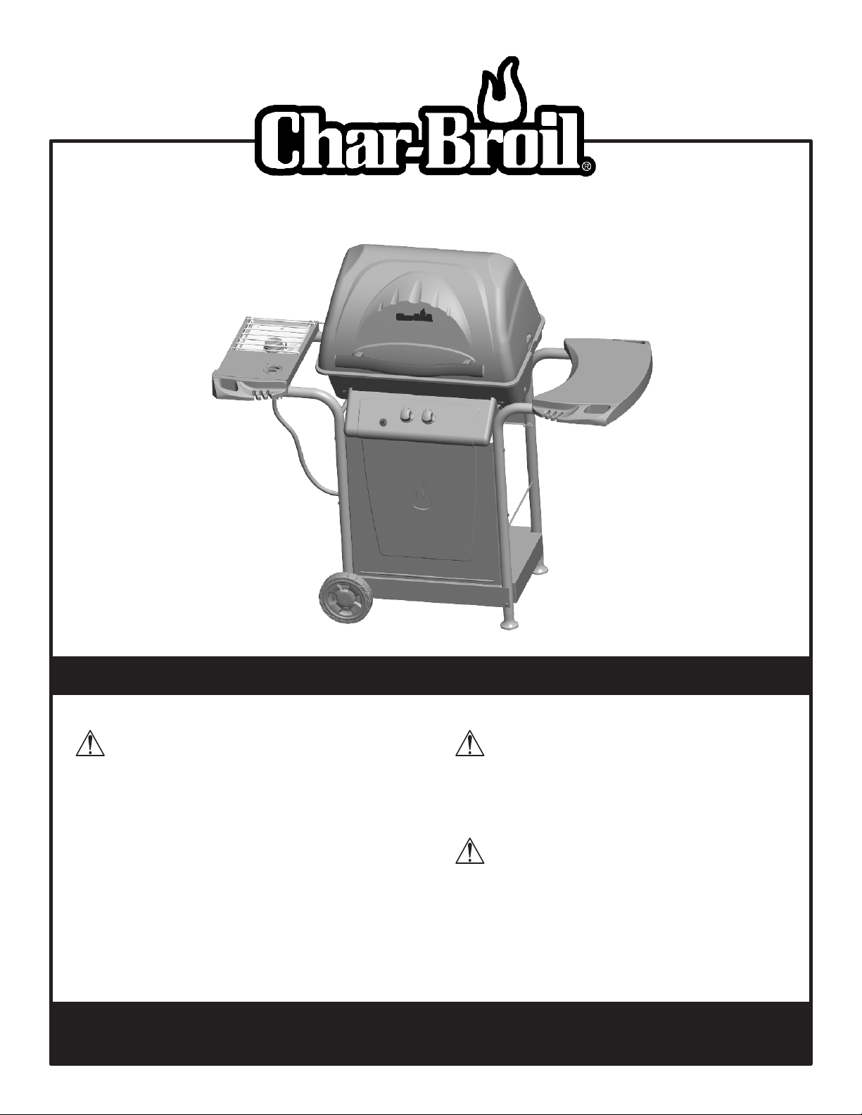
MODEL 463821908 • PRODUCT GUIDE
THIS GRILL IS FOR OUTDOOR USE ONLY.
CAUTION:
Read and follow all safety statements, assembly
instructions, and use and care directions before
attempting to assemble and cook.
INSTALLER/ASSEMBLER:
Leave this manual with consumer.
CONSUMER:
Keep this manual for future reference.
If you have any questions or need assistance during assembly, please call 1-800-241-7548.
To insure your satisfaction and for follow-up service, register your grill online at www.grillregistration.com
WARNING:
Failure to follow all manufacturer’s instructions
could result in serious personal injury and/or
property damage.
CAUTION:
Some parts may contain sharp edges –
especially as noted in the manual! Wear
protective gloves if necessary.
463821908 • 80016556 • 01-10-08
Page 2
DANGER
If you smell gas:
1. Shut off gas to the appliance.
2. Extinguish any open flame.
3. Open lid.
4. If odor continues, keep away from the
appliance and immediately call your gas
supplier or your fire department.
WARNING
Installation Safety Precautions
• Use grill, as purchased, only with LP (propane) gas and the
regulator/valve assembly supplied. A conversion kit must be
purchased for use with natural gas.
• Grill installation must conform with local codes, or in their
absence of local codes, with either the National Fuel Gas
Code, ANSI Z223.1/ NFPA 54, Natural Gas and Propane
Installation Code, CSA B149.1, or Propane Storage and
Handling Code, B149.2, or the Standard for Recreational
Vehicles, ANSI A 119.2/NFPA 1192, and CSA Z240 RV Series,
Recreational Vehicle Code, as applicable.
• All electrical accessories (such as rotisserie) must be
electrically grounded in accordance with local codes, or
National Electrical Code, ANSI / NFPA 70 or Canadian
Electrical Code, CSA C22.1. Keep any electrical cords and/or
fuel supply hoses away from any hot surfaces.
• Grill is not for use in or on recreational vehicles and/or boats.
• This grill is safety certified for use in the United States and/or
Canada only. Do not modify for use in any other location.
Modification will result in a safety hazard.
1. Do not store or use gasoline or other
flammable liquids or vapors in the vicinity of
this or any other appliance.
2. An LP tank not connected for use shall not
er not connected for use shall not
be stored in the vicinity of this or any other
Call Grill Service Center for Help and Parts
• If you need assistance with your product or warranty parts call
1-800-241-7548. Hours of Service Center Operation are
8:00 A.M. To 6:00 P.M. EST Monday - Friday.
• To order non-warranty replacement parts or accessories
please visit us on the web at www.charbroil. com or call
1-800-241-7548 and one of our friendly and knowledgeable
agents will be glad to assist you.
IMPORTANT: Fill out the product record information below.
Model Number
WARNING
CALIFORNIA PROPOSITION 65
1. Combustion by-products produced when using
this product contain chemicals known to the State of
California to cause cancer, birth defects, and other
reproductive harm.
2. This product contains chemicals, including lead
and lead compounds, known to the State of
California to cause cancer, birth defects or other
reproductive harm.
Wash your hands after handling this product.
Safety Symbols
The symbols and boxes shown below explain what each heading
means. Read and follow all of the messages found throughout
the manual.
DANGER
DANGER: Indicates an imminently hazardous situation
which, if not avoided, will result in death or serious injury.
Serial Number
See rating label on grill for serial number.
Date Purchased
CAUTION
For residential use only. Do not use for commercial
cooking.
2 • 463821908
WARNING
WARNING: Indicates an potentially hazardous situation
which, if not avoided, could result in death or serious injury.
CAUTION
CAUTION: Indicates a potentially hazardous situation or
unsafe practice which, if not avoided, may result in minor
or moderate injury.
Page 3
TABLE OF CONTENTS
For Your Safety . . . . . . . . . . . . . . . . . . . . . . . . . . . . . . . . . . . . . . 2
Grill Service Center. . . . . . . . . . . . . . . . . . . . . . . . . . . . . . . . . . . 2
Product Record Information . . . . . . . . . . . . . . . . . . . . . . . . . . . . 2
Installation Safety Precautions . . . . . . . . . . . . . . . . . . . . . . . . . . 2
Safety Symbols. . . . . . . . . . . . . . . . . . . . . . . . . . . . . . . . . . . . . . 2
Use and Care . . . . . . . . . . . . . . . . . . . . . . . . . . . . . . . . . . . . 4-10
Parts List . . . . . . . . . . . . . . . . . . . . . . . . . . . . . . . . . . . . . . . . . . 11
Parts Diagram. . . . . . . . . . . . . . . . . . . . . . . . . . . . . . . . . . . . . . 12
Assembly . . . . . . . . . . . . . . . . . . . . . . . . . . . . . . . . . . . . . . . 13-22
Troubleshooting. . . . . . . . . . . . . . . . . . . . . . . . . . . . . . . . . . 23-25
Limited Warranty. . . . . . . . . . . . . . . . . . . . . . . . . . . . . . . . . . . . 24
Registration Card . . . . . . . . . . . . . . . . . . . . . . . . . . . . . . . . . . . 27
To insure your satisfaction
and for follow-up service,
register your grill
online at:
www.grillregistration.com
WARNING
Do not attempt to repair or alter the
hose/valve/regulator for any “assumed” defect. Any
modification to this assembly will void your warranty
and create the risk of a gas leak and fire. Use only
authorized replacement parts supplied by
manufacturer.
463821908 • 3
Page 4
USE AND CARE
DANGER
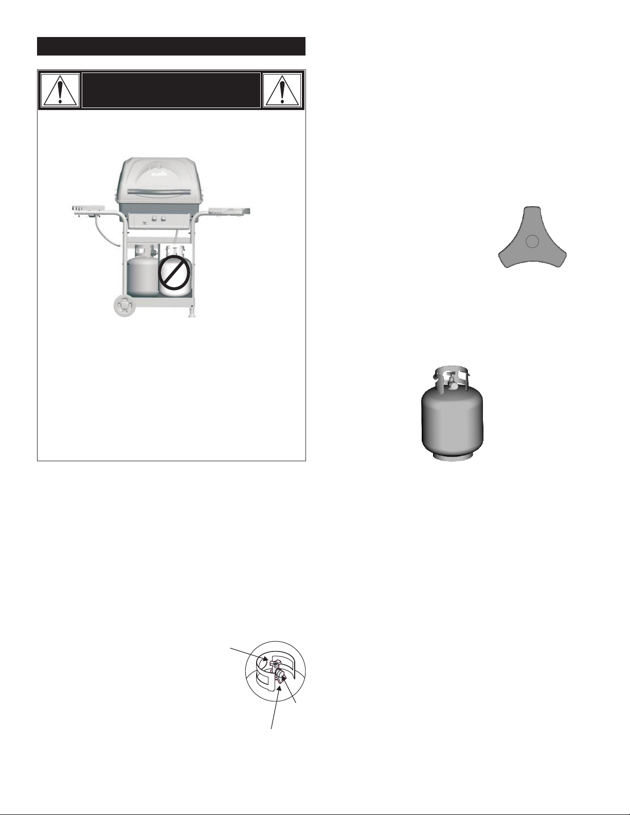
• NEVER store a spare LP tank under or near the
appliance or in an enclosed area.
• Never fill a tank beyond 80% full.
• An over filled or improperly stored tank is a
hazard due to possible gas release from the
safety relief valve.
• If you see, smell or hear gas escaping,
immediately get away from the LP tank/appliance
and call your fire department.
• If the above is not followed exactly, a fire causing
death or serious injury may occur.
LP tank
• The LP tank used with your grill must meet the following
requirements:
• Use LP s only with these required measurements: 12" (30.5cm)
(diameter) x 18" (45.7 cm) (tall) with 20 lb. (9 kg.) capacity
maximum.
• LP tanks must be constructed and marked in accordance with
specifications for LP tanks of the U.S. Department of
Transportation (DOT) or for Canada, CAN/CSA-B339, tanks,
spheres and tubes for transportation of dangerous goods.
Transport Canada (TC). See LP tank collar for marking.
• LP tank valve must have:
• Type 1 outlet compatible with
regulator or grill.
• Safety relief valve.
• UL listed Overfill Protection
Device (OPD). This OPD safety
feature is identified by a unique triangular hand wheel. Use
only LP tanks equipped with this type of valve.
• LP tank must be arranged for vapor withdrawal and include
collar to protect LP tank valve. Always keep LP tanks in upright
position during use, transit or storage.
OPD Hand Wheel
LP tank Removal, Transport and Storage
• Turn OFF all control knobs and LP tank valve. Turn coupling
nut counterclockwise by hand only - do not use tools to
disconnect .Loosen tank screw beneath bottom shelf, then lift
LP tank up and out of cart. Place dust cap on tank valve outlet
whenever the tank is not in use. Only install the type of dust
cap on the tank valve outlet that is provided with the tank
valve. Always use cap and strap supplied with valve. Other
types of caps or plugs may result in leakage of propane.
Failure to use dust cap as directed may result in serious
personal injury and/or property damage.
• A disconnected LP tank in
storage or being transported
must have a dust cap installed (as shown).
Do not store an LP tank in enclosed spaces
such as a carport, garage, porch, covered
patio or other building. Never leave an LP tank
inside a vehicle which may become overheated
by the sun.
• Do not store an LP tank in an area where children play.
LP tank Valve
Dust
Cap
Retainer Strap
LP tank in upright position for vapor withdrawal
LP (Liquefied Petroleum Gas)
• LP gas is nontoxic, odorless and colorless when produced. For
Your Safety, LP gas has been given an odor (similar to rotten
cabbage) so that it can be smelled.
• LP gas is highly flammable and may ignite unexpectedly when
mixed with air.
LP tank Filling
• Use only licensed and experienced dealers.
• LP dealer must purge new tank before filling.
• Dealer should NEVER fill LP tank more than 80% of LP tank
volume. Volume of propane in tank will vary by temperature.
• A frosty regulator indicates gas overfill. Immediately close LP
tank valve and call local LP gas dealer for assistance.
• Do not release liquid propane (LP) gas into the atmosphere.
This is a hazardous practice.
• To remove gas from LP tank, contact an LP dealer or call a
local fire department for assistance. Check the telephone
directory under “Gas Companies” for nearest certified LP
dealers.
4 • 463821908
Page 5
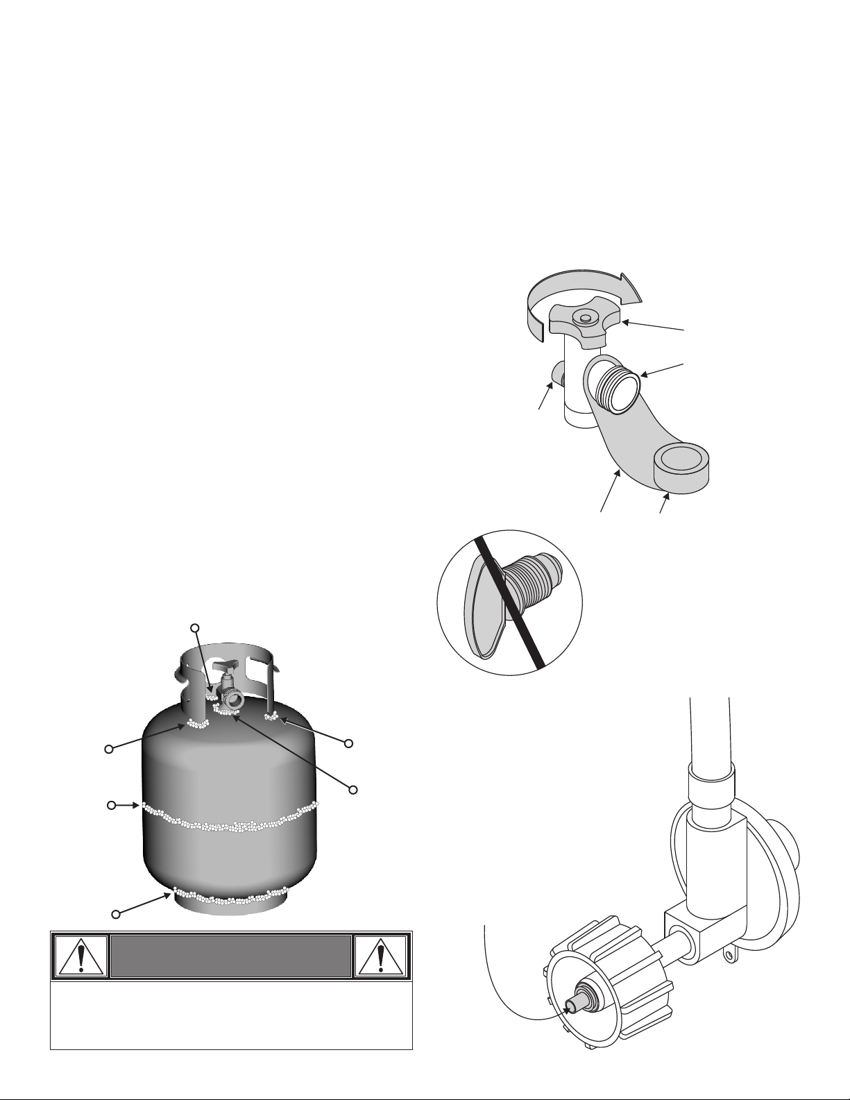
LP tank Exchange
Connecting Regulator to the LP tank
• Many retailers that sell grills offer you the option of replacing
your empty LP tank through an exchange service. Use only
those reputable exchange companies that inspect, precision fill,
test and certify their tanks. Exchange your tank only for an
OPD safety feature-equipped tank as described in the "LP
tank" section of this manual.
• Always keep new and exchanged LP tanks in upright position
during use, transit or storage.
• Leak test new and exchanged LP tanks BEFORE
connecting to grill.
LP tank Leak Test
For your safety
• Leak test must be repeated each time LP tank is exchanged or
refilled.
• Do not smoke during leak test.
• Do not use an open flame to check for gas leaks.
• Grill must be leak tested outdoors in a well-ventilated area,
away from ignition sources such as gas fired or electrical
appliances. During leak test, keep grill away from open flames
or sparks.
• Use a clean paintbrush and a 50/50 mild soap and water
solution.
in figure below.
s Do not use household cleaning agents. Damage to gas
train components can result.
Brush soapy solution onto areas indicated by arrows
1. LP tank must be properly secured onto grill. (Refer to
assembly section.)
2. Turn all control knobs to the OFF position.
3. Turn LP tank OFF by turning hand-wheel clockwise to a full
stop.
4. Remove the protective cap from LP tank valve. Always use
cap and strap supplied with valve.
c
k
w
o
i
l
s
e
Strap and Cap
OPD Hand Wheel
Type 1 outlet with
thread on outside
Safety Relief Valve
C
f
f
O
Do not use a POL transport plug
(plastic part with external threads)!
It will defeat the safety feature of
the valve.
WARNING
If “growing” bubbles appear do not use or move the LP
tank. Contact an LP gas supplier or your fire department!
5. Hold regulator and insert nipple into LP
tank valve. Hand-tighten the coupling
nut, holding regulator in a straight line
with LP tank valve so as not to crossthread the connection.
Continued on next page.
Nipple has to be centered
into the LP tank valve.
463821908 • 5
Page 6
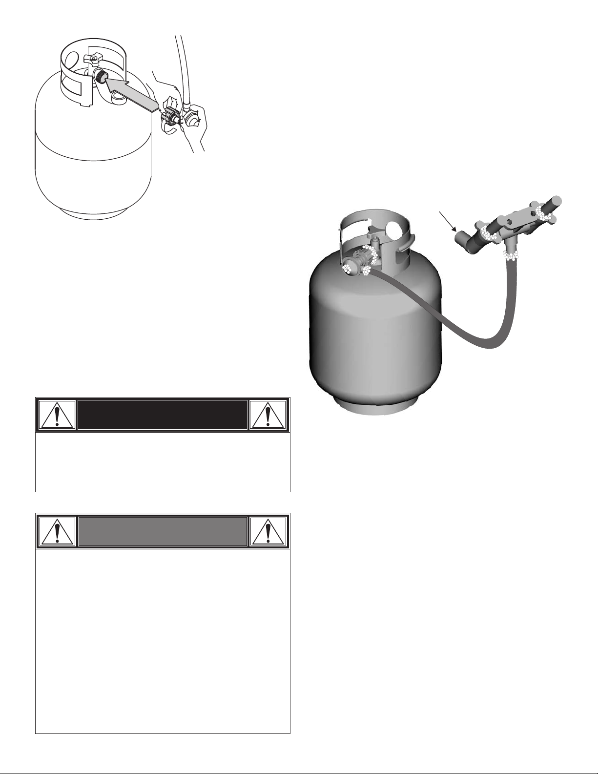
Leak Testing Valves, Hose and Regulator
1. Turn all grill control knobs to OFF.
Straight
Hold coupling nut and regulator
as shown for proper connection
to LP tank valve.
6. Turn the coupling nut clockwise and tighten to a full stop. The
regulator will seal on the back-check feature in the LP tank
valve, resulting in some resistance. An additional one-half to
three-quarters turn is required to complete the
connection. Tighten by hand only – do not use tools.
NOTE:
If you cannot complete the connection, disconnect regulator and
repeat steps 5 and 6. If you are still unable to complete the
connection, do not use this regulator!
2. Be sure regulator is tightly connected to LP tank.
3. Completely open LP tank valve by turning hand wheel
counterclockwise. If you hear a rushing sound, turn gas off
immediately. There is a major leak at the connection. Correct
before proceeding.
4. Brush soapy solution onto areas circled below.
s Never remove threaded
orifice at end of valve.
DANGER
• Do not insert any tool or foreign object into the valve
outlet or safety relief valve. You may damage the valve
and cause a leak. Leaking propane may result in
explosion, fire, severe personal injury, or death.
WARNING
• Outdoor gas appliance is not intended to be installed
in or on a boat.
• Outdoor gas appliance is not intended to be installed
in or on an RV.
• Never attempt to attach this grill to the self-contained
LP gas system of a camper trailer or motor home.
• Do not use grill until leak-tested.
• If a leak is detected at any time, STOP and call the fire
department.
• If you cannot stop a gas leak, immediately close
Lptank valve and call LP gas supplier or your fire
department!
5. If “growing” bubbles appear, there is a leak. Close LP tank
valve immediately and retighten connections. If leaks cannot
be stopped do not try to repair. Call for replacement parts.
Order new parts by giving the serial, model number and name
and part number of items needed (see parts list) to the Grill
Service Center at 1-800-241-7548.
6. Always close LP tank valve after performing leak test by
turning hand wheel clockwise.
6 • 463821908
Page 7
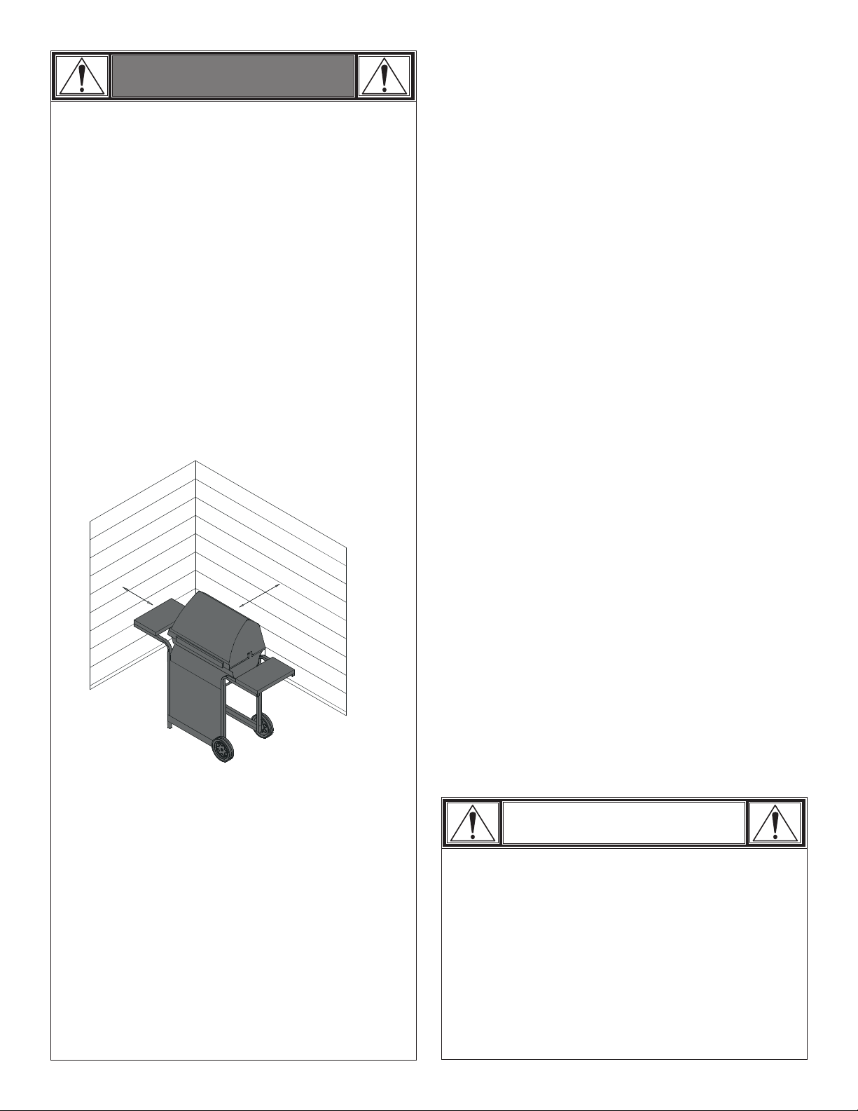
WARNING
For Safe Use of Your Grill and to Avoid Serious
Injury:
• Do not let children operate or play near grill.
• Keep grill area clear and free from materials that burn.
• Do not block holes in sides or back of grill.
• Check burner flames regularly.
• Use grill only in well-ventilated space. NEVER use in
enclosed space such as carport, garage, porch,
covered patio, or under an overhead structure of any
kind.
• Do not use charcoal or ceramic briquets in a gas grill.
(Unless briquets are supplied with your grill.)
• Use grill at least 3 ft. from any wall or surface.
Maintain 10 ft. clearance to objects that can catch fire
or sources of ignition such as pilot lights on water
heaters, live electrical appliances, etc..
Safety Tips
sBefore opening LP tank valve, check the coupling nut for
tightness.
sWhen grill is not in use, turn off all control knobs and LP tank
valve.
sIf the outdoor cooking gas appliance is not in use, the gas
must be turned off at the supply tank. Storage of an outdoor
cooking gas appliance indoors is permissible only if the tank
is disconnected and removed from the appliance.
sNever move grill while in operation or still hot.
sUse long-handled barbecue utensils and oven mitts to avoid
burns and splatters.
sMaximum load for side shelves is 10 lbs.
sThe grease cup must be inserted into grease clip and
emptied after each use. Do not remove grease cup until grill
has completely cooled.
s Clean grill often, preferably after each cookout. If a bristle
brush is used to clean any of the grill cooking surfaces,
ensure no loose bristles remain on cooking surfaces prior to
grilling. It is not recommended to clean cooking surfaces
while grill is hot.
sIf you notice grease or other hot material dripping from grill
onto valve, hose or regulator, turn off gas supply at once.
Determine the cause, correct it, then clean and inspect valve,
hose and regulator before continuing. Perform a leak test.
sThe regulator may make a humming or whistling noise during
operation. This will not affect safety or use of grill.
sOnly use the pressure regulator and hose assembly supplied
with this grill. Replacement pressure regulator and hose
assemblies must be specified or supplied by Char-Broil, LLC.
sIf you have a grill problem see the "Troubleshooting Section".
sIf the regulator frosts, turn off grill and LP tank valve
immediately. This indicates a problem with the tank and it
should not be used on any product. Return to supplier!
• Apartment Dwellers:
Check with management to learn the requirements
and fire codes for using an LP gas grill in your
apartment complex. If allowed, use outside on the
ground floor with a three (3) foot clearance from walls
or rails. Do not use on or under balconies.
• NEVER attempt to light burner with lid closed. A
buildup of non-ignited gas inside a closed grill is
hazardous.
• Never operate grill with LP tank out of correct
position specified in assembly instructions.
• Always close LP tank valve and remove coupling
nut before moving LP tank from specified
operation position.
CAUTION
• Putting out grease fires by closing the lid is not
possible. Grills are well ventilated for safety
reasons.
• Do not use water on a grease fire. Personal injury
may result. If a grease fire develops, turn knobs
and LP tank off.
• Do not leave grill unattended while preheating or
burning off food residue on HI. If grill has not been
regularly cleaned, a grease fire can occur that may
damage the product.
463821908 • 7
Page 8
Ignitor Lighting
s Do not lean over grill while lighting.
1. Turn OFF gas burner control valves.
2.Turn ON gas source or tank.
3. Open lid during lighting.
4. To ignite, turn ignition left knob to PRE-HEAT ,Go to step 3 .
5. Push IGNITOR button rapidly.
6. If ignition doe NOT occur in 5 seconds, turn the burner
controls OFF, wait 5 minutes and repeat the lighting
procedure.
7. To ignite right burner, turn right knob to PRE-HEAT.
If ignitor does not work, follow match lighting instructions.
CAUTION
If ignition does NOT occur in 5 seconds, turn the
burner controls OFF, wait 5 minutes and repeat the
lighting procedure. If the burner does not ignite with
the valve open, gas will continue to flow out of the
burner and could accidently ignite with risk of injury.
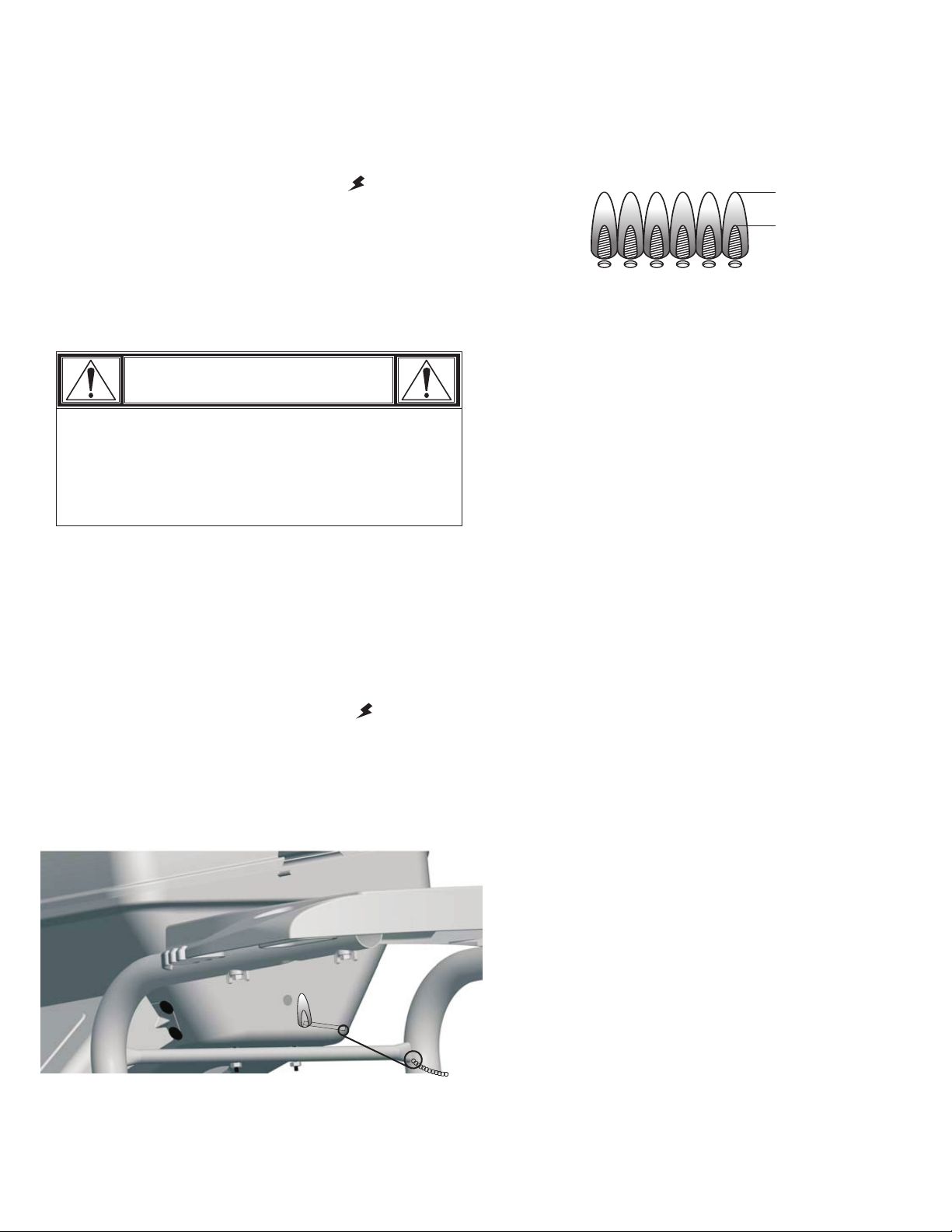
Match-Lighting
s Do not lean over grill while lighting.
1. Open lid during lighting. Turn on gas at LP tank.
2. Place lit match into match holder, then into side of grill bottom
(as shown below).
3. Push in and turn IGNITION BURNER knob to HI. Be sure
burner lights and stays lit.
4. To ignite right burner, turn right knob to HI.
Burner Flame Check
• Remove cooking grates and flame tamers. Light burners, rotate
knobs from HI to LO. You should see a smaller flame in LO
position than seen on HI. Always check flame prior to each use.
If only low flame is seen refer to "Sudden drop or low flame" in
the Troubleshooting Section.
HI
LO
Turning Grill Off
• Turn all knobs to position. Turn LP tank off by turning
hand-wheel clockwise to a full stop.
OFF
Ignitor Check
• Turn gas off at LP tank. Press ignitor button rapidly. "Click"
should be heard and spark seen each time between collector
box or burner and electrode. See "Troubleshooting" if no click
or spark.
Valve Check
• Important: Make sure gas is off at LP tank before checking
valves. Knobs lock in position. To check valves, first
push in knobs and release, knobs should spring back. If knobs
do not spring back, replace valve assembly before using grill.
Turn knobs to LO position then turn back to position.
Valves should turn smoothly.
OFF
OFF
Hose Check
• Before each use, check to see if hoses are cut or worn.
Replace damaged hoses before using grill. Use only
valve/hose/regulator specified by manufacturer.
General Grill Cleaning
• Do not mistake brown or black accumulation of grease and
smoke for paint. Interiors of gas grills are not painted at the
factory (and should never be painted). Apply a strong solution
of detergent and water or use a grill cleaner with scrub brush
on insides of grill lid and bottom. Rinse and allow to completely
air dry. Do not apply a caustic grill/oven cleaner to painted
surfaces.
• Plastic parts: Wash with warm soapy water and wipe dry.
s Do not use citrisol, abrasive cleaners, degreasers or a
concentrated grill cleaner on plastic parts. Damage to and
failure of parts can result.
• Porcelain surfaces: Because of glass-like composition, most
residue can be wiped away with baking soda/water solution or
specially formulated cleaner. Use nonabrasive scouring powder
for stubborn stains.
• Painted surfaces: Wash with mild detergent or nonabrasive
cleaner and warm soapy water. Wipe dry with a soft
nonabrasive cloth.
• Cooking surfaces: If a bristle brush is used to clean any of
the grill cooking surfaces, ensure no loose bristles remain on
cooking surfaces prior to grilling. It is not recommended to
clean cooking surfaces while grill is hot.
8 • 463821908
Page 9
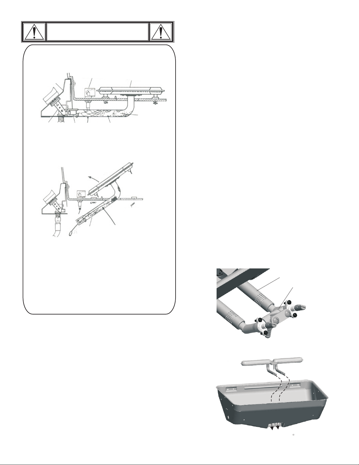
CAUTION
SPIDER ALERT!
GAS COLLECTOR
BOX & IGNITOR
CONTROL PANEL
VALVE
If you notice that your grill is getting hard to light or that the
flame isn’t as strong as it should be, take the time to check and
clean the venturi’s.
In some areas of the country, spiders or small insects have been
known to create “flashback” problems. The spiders spin webs, build
nests and lay eggs in the grill’s venturi tube(s) obstructing the flow of
gas to the burner. The backed-up gas can ignite in the venturi behind
the control panel. This is known as a flashback and it can damage
your grill and even cause injury.
To prevent flashbacks and ensure good performance the burner and
venturi assembly should be removed from the grill and cleaned
before use whenever the grill has been idle for an extended period.
AIR
SHUTTER
LIFT OUT
BURNER ASSEMBLY
CLEAN OUT
VENTURI
VENTURI
INSIDE VENTURI
SPIDER WEBS
BURNER
REMOVE
BURNER
CLIPS
SPIDER WEBS
INSIDE VENTURI
Cleaning the Burner Assembly
Follow these instructions to clean and/or replace parts of burner
assembly or if you have trouble igniting grill.
1. Turn gas off at control knobs and LP tank.
2. vaporiser b
Remove cooking grate and ar.
3.
Under grill remove grease cup, disconnect ignitor wire and
clips from burner. To remove clips pull down on large end of
clip attached to the valve, turn away from valve, rotate
upward and remove small end of clip from burner tube (A).
4.
Inside grill remove burner assembly (B), clean ceramic
portion of electrode with rubbing alcohol and a swab.
5.
Clean outside of burner with soap and water. Lay burner
upside down on flat surface, insert garden hose to force
water through tubes. Make sure water comes out of all
burner holes. Open clogged holes with a thin wire. Shake
out excess water and examine holes. Due to normal wear
and corrosion some holes may become enlarged. If any
large cracks or holes are found replace burner.
6.
If grill is to be stored, coat burner lightly with cooking oil.
Wrap in protective cover to keep insects out.
7.
If not storing grill after cleaning, replace burner into grill
bottom.
8.
To reattach clips hold large curved end away from burner
tube, insert small curved end into hole under burner tubes,
turn clip towards valve, snap into place.
VERY IMPORTANT: Burner tubes must reengage valve
openings. See illustration (A).
9. electrode
Reattach ignitor wire to .
10. vaporiser
Reposition bar and cooking grate. Reattach clean
grease cup
11.
Before cooking again on grill, perform a “Leak Test” and
“Burner Flame Check”.
to grease clip.
Burner Tube
Valve
Storing Your Grill
• Clean cooking grates.
• Store in dry location.
• Cover grill if stored outdoors. Choose from a variety of grill
covers offered by manufacturer.
• When LP tank is connected to grill, store outdoors in a wellventilated space and out of reach of children.
• If the outdoor cooking gas appliance is not in use, the gas must
be turned off at the supply tank. Storage of an outdoor cooking
gas appliance indoors is permissible only if the tank is
disconnected and removed from the appliance.
• Store grill indoors ONLY if LP tank is turned off and
disconnected, removed from grill and stored outdoors.
• When removing grill from storage, follow “Cleaning the Burner
Assembly” instructions before starting grill.
A
Correct burner-to-valve engagement
B
463821908 • 9
Page 10

Food Safety
Food safety is a very important part of enjoying the outdoor
cooking experience. To keep food safe from harmful bacteria,
follow these four basic steps:
Clean: Wash hands, utensils, and surfaces with hot soapy water
before and after handling raw meat and poultry.
Separate: Separate raw meats and poultry from ready-to-eat
foods to avoid cross contamination. Use a clean platter and
utensils when removing cooked foods.
Cook: Cook meat and poultry thoroughly to kill bacteria. Use a
thermometer to ensure proper internal food temperatures.
Chill: Refrigerate prepared foods and leftovers promptly.
For more information call: USDA Meat and Poultry Hotline at
1-800-535-4555 In Washington, DC (202) 720-3333, 10:00 am4:00 pm EST.
How To Tell If Meat Is Grilled Thoroughly
• Meat and poultry cooked on a grill often browns very fast on the
outside. Use a meat thermometer to be sure food has reached
a safe internal temperature, and cut into food to check for
visual signs of doneness.
• Whole poultry should reach 180° F; breasts, 170° F. Juices
should run clear and flesh should not be pink.
• Hamburgers made of any ground meat or poultry should reach
160° F, and be brown in the middle with no pink juices. Beef,
veal and lamb steaks, roasts and chops can be cooked to 145°
F. All cuts of pork should reach 160° F.
• NEVER partially grill meat or poultry and finish cooking later.
Cook food completely to destroy harmful bacteria.
• When reheating takeout foods or fully cooked meats like hot
dogs, grill to 165° F, or until steaming hot.
10 • 463821908
Page 11

PARTS LIST – Model No. 463821908
Key Qty Description . . . . . . . . . . . . . . . . . . . Part #
A 1 Firebox. . . . . . . . . . . . . . . . . . . . . 80011600
B 1 Valve/Hose/Regulator . . . . . . . . . 80016425
C 1 Control Panel . . . . . . . . . . . . . . . . 80016558
D 2 Control Knobs . . . . . . . . . . . . . . . 80008245
E 1 Ignitor. . . . . . . . . . . . . . . . . . . . . . 5156113
F 2 Axle F/Wheel . . . . . . . . . . . . . . . . 80011619
G 1 Left Cart Assy w/match holder. . . 80011604
H 1 Burner Assembly . . . . . . . . . . . . . 80011601
I 2 Wheels. . . . . . . . . . . . . . . . . . . . . 80008000
J 1 Right Cart Leg . . . . . . . . . . . . . . . 80011605
K 2 Leg Extenders . . . . . . . . . . . . . . . 80008291
L 1 Bottom Shelf . . . . . . . . . . . . . . . . 80011606
M 1 Back Support Brace. . . . . . . . . . . 80011607
N 1 Tank Retainer. . . . . . . . . . . . . . . . 80008294
O 1 Front Panel . . . . . . . . . . . . . . . . . 80011608
P 1 Side Shelf . . . . . . . . . . . . . . . . . . 80011609
Q 1 Lid . . . . . . . . . . . . . . . . . . . . . . . . 80011610
R 1 Logo Plate Assembly . . . . . . . . . . 80011611
S 1 Handle Assembly. . . . . . . . . . . . . 80011612
T 1 Sideburner Frame . . . . . . . . . . . . 80011613
U 1 Sideburner Pan . . . . . . . . . . . . . . 80011614
V 1 Sideburner Grate . . . . . . . . . . . . . 80010163
W 1 Tool Holder. . . . . . . . . . . . . . . . . . 80011615
X 1 Sideburner Valve Cup . . . . . . . . . 80011616
Y 1 Sideburner . . . . . . . . . . . . . . . . . . 80016559
Z 1 Sideburner Knob . . . . . . . . . . . . . 80010161
Key Qty Description . . . . . . . . . . . . . . . . . . . Part #
AA 1 Heat Tent . . . . . . . . . . . . . . . . . . . 80008273
BB 1 Cooking Grate . . . . . . . . . . . . . . . 80008274
CC 1 Swing Away . . . . . . . . . . . . . . . . . 80008275
DD 2 Lower Hinge. . . . . . . . . . . . . . . . . 80011618
EE 2 Upper Hinge. . . . . . . . . . . . . . . . . 80011617
FF 1 Grease Cup . . . . . . . . . . . . . . . . . 80000270
GG 1 Clip, Grease Cup. . . . . . . . . . . . . 80000271
HH 1 Heat Shield F/Tank . . . . . . . . . . . 80016679
II 1 Heat Shield F/Firebox . . . . . . . . . 80016680
1 Product Manual, English . . . . . . . 80016556
1 Hardware Pack . . . . . . . . . . . . . . 80009105
1 Venturi Clip
2 Axle Bolt
6 Wing Nut, Plastic
7 #10-24x2" Carriage Bolt
4 Hitch Pin
22 #10-24 Flange Nut
28 Silicone Washer
4 #10-24x1-1/4" Machine Screw
3 #10-24 Wing Nut, Metal
5 #10-24 T-Wing Screw
6 #10-24x2" Machine Screw
16 #10-24x1/2" Machine Screw
2 Insulation Washer
2 Hinge Pin
Certified Grill Parts And Accessories®, Char-Broil and Design®, Char-Broil (Gas Grill Briquettes)®, Char-Diamonds®, Cooking Zone and Design®, Diamond Flame®, Executive Chef®, Faststart®, Flare
Fighter®, FlavorMaster®, Gas Grill Silouette and Design®, H2O Smoker®, Lava Flame®, MasterFlame®, MasterFlame Precision Cooking System®, PowerSpark®, Quantum®, VIP®, PrecisionFlame and
Design®, Sierra®, and TruFlame® are registered Trademarks of the W.C. Bradley Company. Thermos® is a registered trademark of the Thermos Company and its affiliates.
Artisan Collection by Char-Broil ™, C3 and Design™, Char-Broil and Design™, Flame Design™, FlavorTents™, Grill 2 Go™, Grillin’ Stick™, Keeper of the Flame™, Keepers of the Flame™, Natural Grip™,
Outdoor Cooking Collection and Design™, Patio Bistro™, PrecisionFlame™, Pro-Check™, QuickSet Grills and Design™, SmokerTents™, The Big Easy™, The Minute Grill™, The Edge™, The Tuscan
Collection™, and The Urban Grill™ are Trademarks of the W.C. Bradley Company. Universal Grill Parts and Design™ is a trademark of the Thermos Company and its affiliates.
Protected under one or more of the following U.S. Patents: 4,598,692; 4,624,240; 4,747,391; 4,747,391; 4,817,583; 4,924,846; 4,989,579; 5,003,960; 5,076,256; 5,076,257; 5,090,398; 5,109,834; 5,224,676;
5,277,106; 5,421,319; 5,441,226; 5,452,707; 5,458,309; 5,566,606; 5,566,606; 5,579,755; 5,582,094; 5,613,486; 5,649,475; 5,706,797; 5,711,663; 5,765,543; 5,931,149; 5,996,573; 6,095,132; 6,135,104;
6,173,644B1; 6,279,566; 6,397,731; 6,418,923; 6,439,222; 6,523,461; 6,935,327; D282,619; D339,714; D341,292; D343,337; D358,059; D361,466; D364,535; D372,637; D373,701; D377,735; D383,035;
D397,910; D405,643; D405,643; D406,005; D406,009; D413,043; D413,229; D413,229; D414,982; D415,388; D416,164; D416,441; D416,441; D417,587; D422,516; D423,274; D423,876; D428,303; D435,396;
D436,004; D438,059; D438,060; D438,427; D439,110; D442,505; D443,179; D443,354; D447,384; D447,385; D447,909; D448,610; D448,614; D448,615; D448,616; D448,975; D449,492; D451,759; D456,202S;
D460,313, D461,359 and D504,048. Canada: 87743; 87744; 92607; 92608 and 1,316,424. Other Patents Pending. Assembly instructions © 2006.
463821908 • 11
Page 12
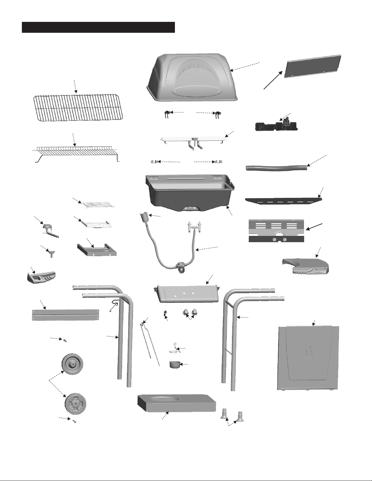
PARTS DIAGRAM – Model No. 463821908
BB
Q
II
R
CC
EE
H
S
DD
AA
V
Y
Z
U
T
X
A
B
HH
P
W
C
M
12 • 463821908
N
E
F
G
D
J
O
GG
FF
I
F
L
K
Page 13
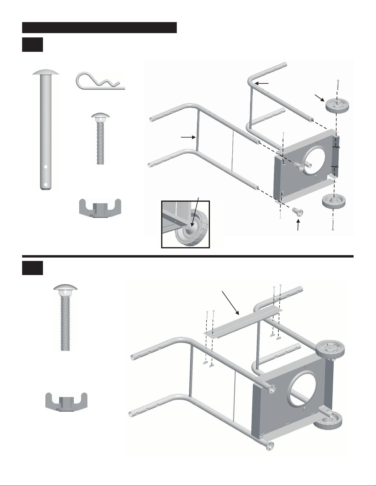
ASSEMBLY – Model No. 463821908
1
Axle Bolt
A Attach right leg assembly to bottom shelf with (2) #10-24x2" carriage bolts and #10-24 Plastic wing nuts.
B Push Leg Extenders into the bottom of the right legs.
C Place left leg assembly into bottom shelf. Insert axle bolts into wheels, legs and bottom shelf. Secure with hitch pins.
Left Leg Assembly
1” Hitch Pin
Qty.2
Right Leg Assembly
#10-24 X 2” Carriage Bolt
Qty.2
“Cone” side of wheel against leg
Qty.2
Wheel
Bottom
Shelf
#10-24 Plastic Wing Nuts
Attach back support brace to legs with (4) #10-24x2" carriage bolts and #10-24 Plastic wing nuts.
2
#10-24 X 2” Carriage Bolt
Qty.4
Qty.2
Leg Extender
Back Support Brace
#10-24 Plastic Wing Nuts
Qty.4
463821908 • 13
Page 14
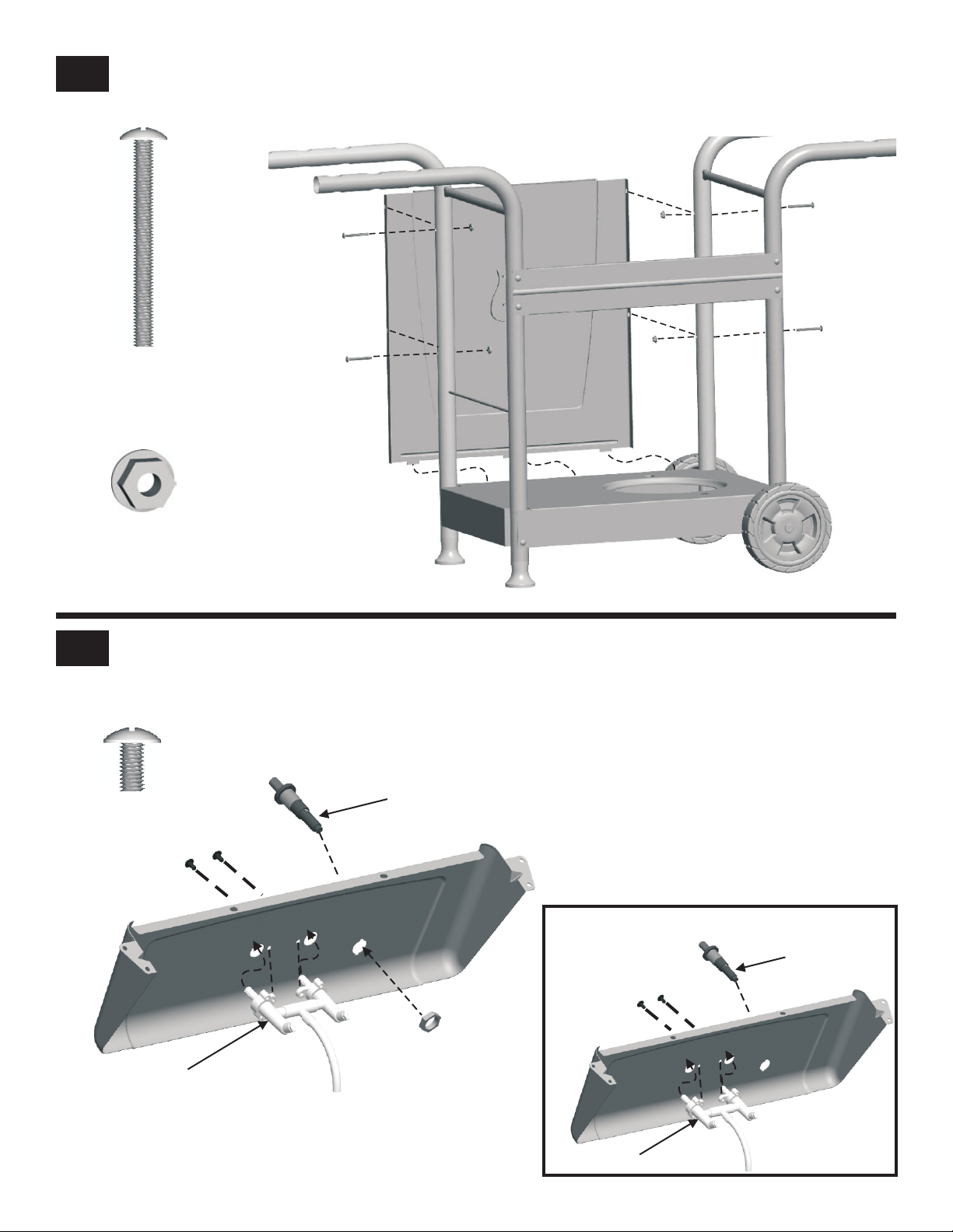
3
#10-24 X 2”
Machine Screw
A Place bottom of front panel into three slots in the bottom shelf.
B Attach front panel to legs with four #10-24x2" machine screws and #10-24 flange nuts.
Qty.4
#10-24 Flange Nut
Qty.4
A Place valve/hose/regulator onto control panel. Attach with machine screws. NOTE: Make sure the two valve
4
stems are centered in their clearance holes; otherwise, this can cause main burner level problems.
B Insert ignitor body into ignitor hole on control panel, then tighten it with sheetmetal nut. NOTE: if your grill come with
Snap-in ignitor, please see Option.
#10-24 x ½”
Machine Screw
Qty.2
Ignitor
#10-24 x ½”
Option: Snap the
ignitor into the control
panel.
Back of Cart
Snap-in
Ignitor
14 • 463821908
Sheetmetal Nut
Valve/Hose/Regulator
Valve/Hose/Regulator
Page 15
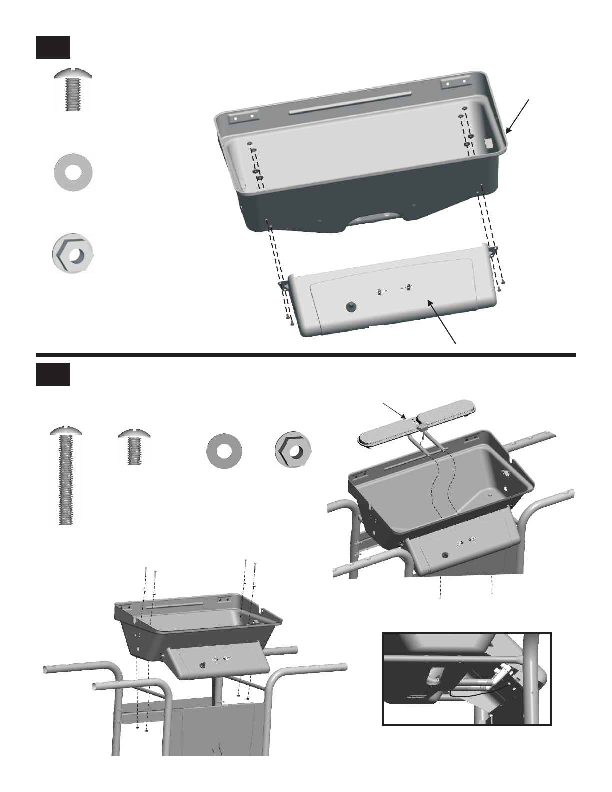
Attach control panel to firebox using #10-24 x ½” machine screws, silicon washers and #10-24 flange nuts.
5
#10-24 x ½”
Machine Screw
Qty. 4
Silicon Washer
Qty. 4
#10-24
Flange Nut
Qty. 4
Firebox
A Place firebox onto cart, make sure the regulator hose hangs inside cart and control panel overlaps front panel.Attach to cart with
6
#10-24x1-1/4"
Machine Screw
#10-24x1-1/4" machine screws, Silicon washers and #10-24 flange nuts.
B Place burners assembly into firebox, making sure valves are inside the burner tubes. Attach to firebox with
machine screws and silicon washers.
C Attach wire of main burner to ignitor.
Qty: 4
#10-24 x ½”
Machine Screws
Qty. 2
Silicon Washer
A
Firebox
Qty: 6
Control Panel
#10-24 x ½”
Burner Assembly
B
#10-24
Flange Nuts
Qty. 4
Correct burner-to-valve engagement
Front Panel
C
463821908 • 15
Page 16
7
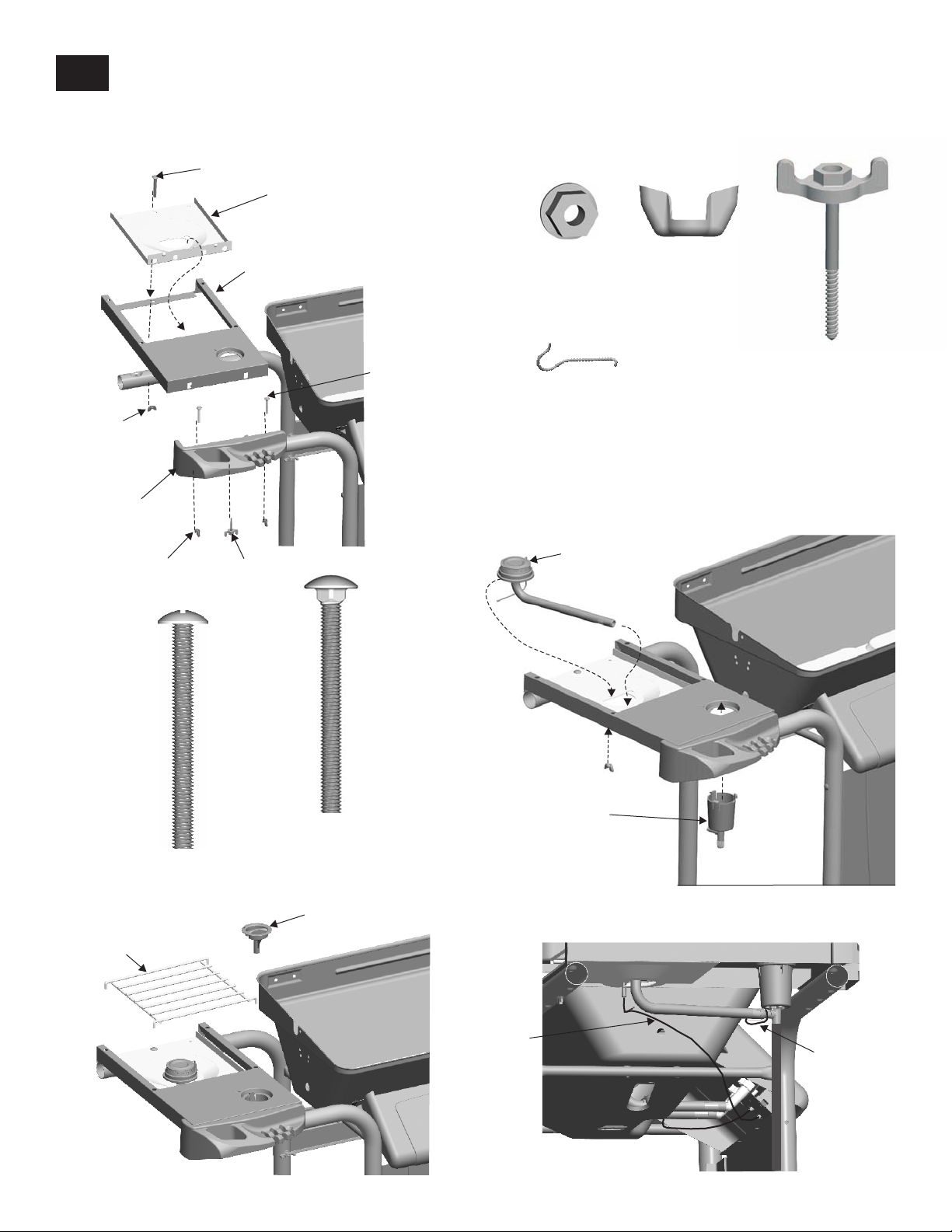
A Attach tool holder to front leg using two #10-24x2" machine screws and #10-24 flange nuts. Place sideburner pan into frame and
attach with a #10-24x2" carriage bolt and #10-24 metal wing nut in back and a T-wing screw in front.
B Attach sideburner valve cup. Place sideburner into hole. Make sure side burner valve is inside sideburner tube. Fasten sideburner
with a wing nut. Hook burner clip to sideburner tube and around manifold. Attach sideburner ignitor wire to ignitor.
C Place sideburner knob and grate.
#10-24x2" Carriage Bolt
A
Sideburner Pan
Metal
Wing Nut
Tool
Holder
Flange Nut
Sideburner Frame
T-Wing
Screw
#10-24x2"
Machine Screw
#10-24
Flange Nut
Qty: 2
Sideburner Clip
Qty: 1
Sideburner
#10-24
Metal Wing Nut
Qty. 1
#10-24
T-Wing Screw
Qty: 1
Machine Screw
Sideburner Grate
C
16 • 463821908
#10-24 X 2”
Qty. 2
#10-24x2”
Carriage Bolts
Qty: 1
Sideburner
Knob
Sideburner
ignitor wire
Sideburner
Valve
Cup
Correctly assembled valve in sideburner tube
B
Sideburner
Clip
Page 17
8
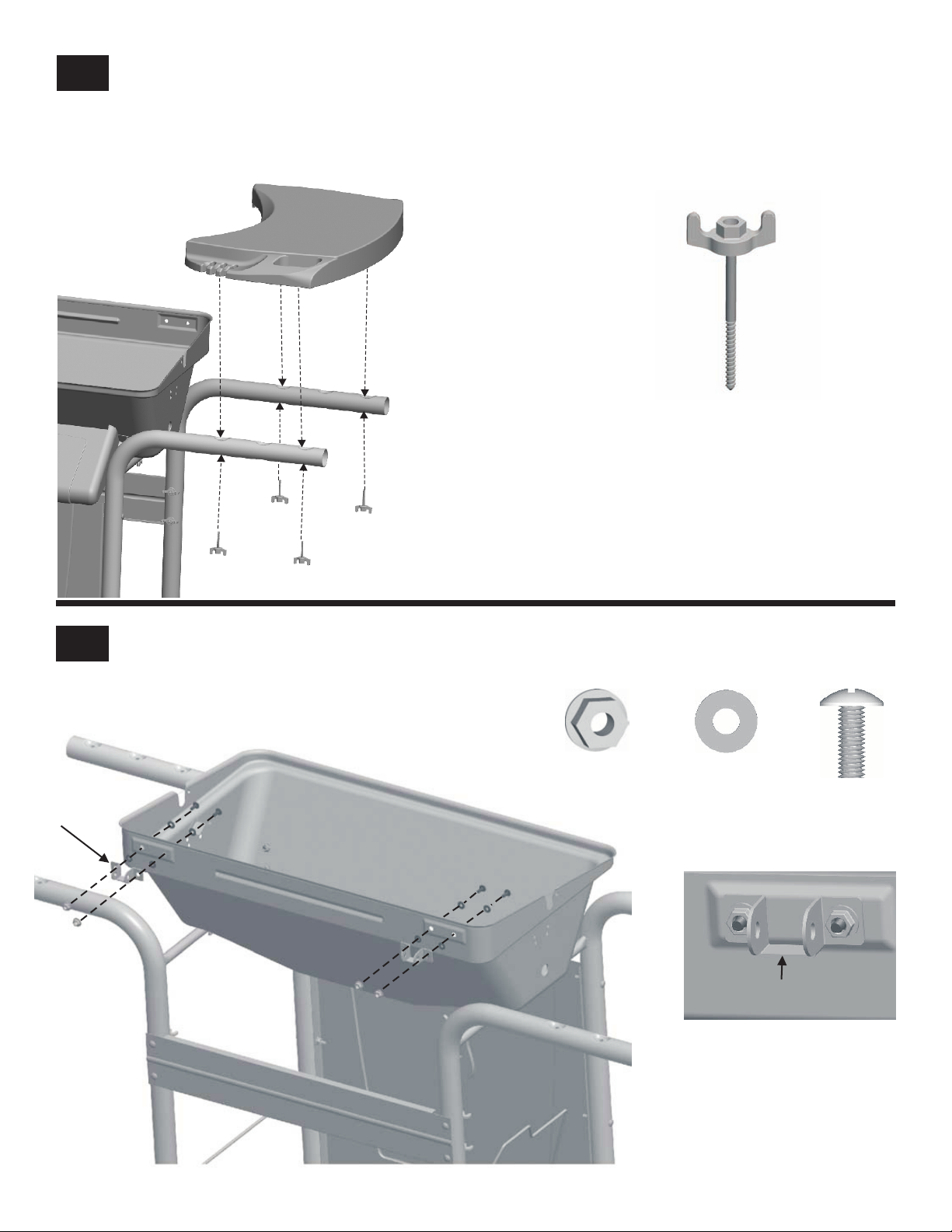
Attach side shelf with #10-24 T-wing screw.
#10-24
T-Wing Screw
Qty: 4
9
Lower Hinge
Attach lower lid hinges to back of firebox using #10-24x1/2" machines screws, silicon washers and #10-24 flange nuts per hinge.
The center flat portion of the hinge should be at the bottom (see inset).
#10-24
Flange Nuts
Qty:4
Silicon Washer
Qty:8
Center flat portion
of hinge on bottom
#10-24 X ½”
Machine Screw
Qty:4
463821908 • 17
Page 18
10
#10-24 Wing Nut
Machine Screw
Silicon Washer
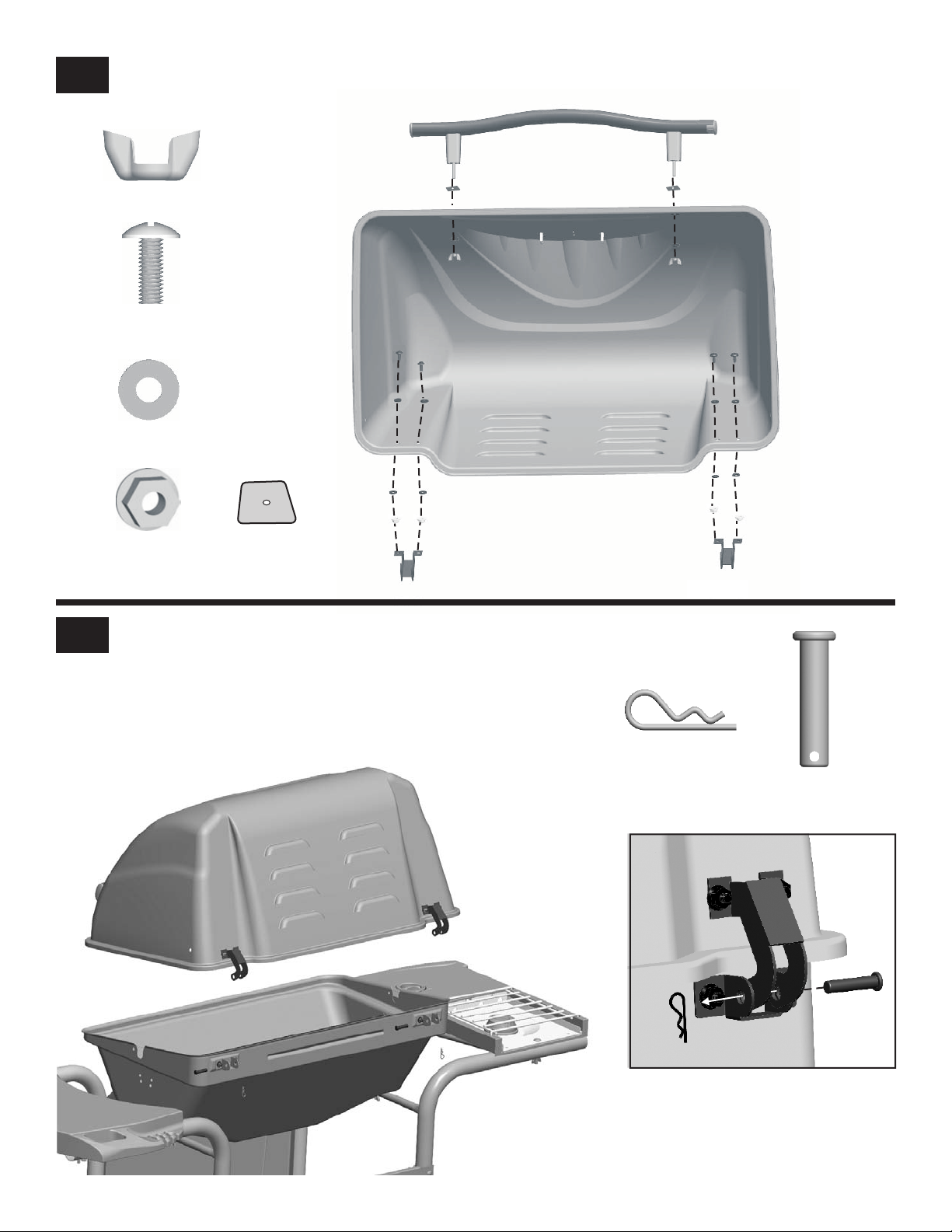
Attach handle to front of lid with silicon washers , insulation washers and #10-24 wing nuts. Upper lid hinges attach to back with
#10-24x1/2" machine screws, fiber washers and #10-24 flange nuts. Do not tighten the screws.
Qty:2
#10-24X1/2”
Qty:4
Qty:10
11
#10-24
Flange Nuts
Qty:4
Place lid assembly onto firebox, aligning hinges. Hinges on lid fit inside hinges on firebox. Secure with
hinge pins and hitch pins. Tighten upper lid hinges .screws
Insulation Washer
Qty:2
1” Hitch Pin
Qty. 2
Hinge Pin
Qty. 2
18 • 463821908
Page 19
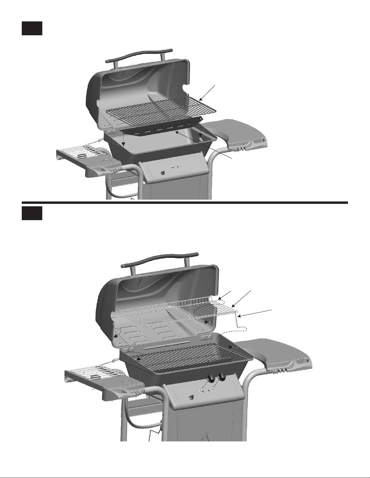
12
Place heat tent onto V-shaped bar rests inside firebox. Place cooking grate onto firebox.
Cooking Grate
Heat Tent
13
A Insert ends of Swing Away pivot wire into holes in sides of grill lid. Insert ends of Swing Away leg wire into holes in sides of
firebox. NOTE: Pivot and leg wires, running side-to-side, should be under wires running front-to-back. If pivot and leg wires are
on top Swing Away is installed upside-down.
B Push control knobs onto valves.
Pivot Wire
Swing Away
Leg
A
B
463821908 • 19
Page 20
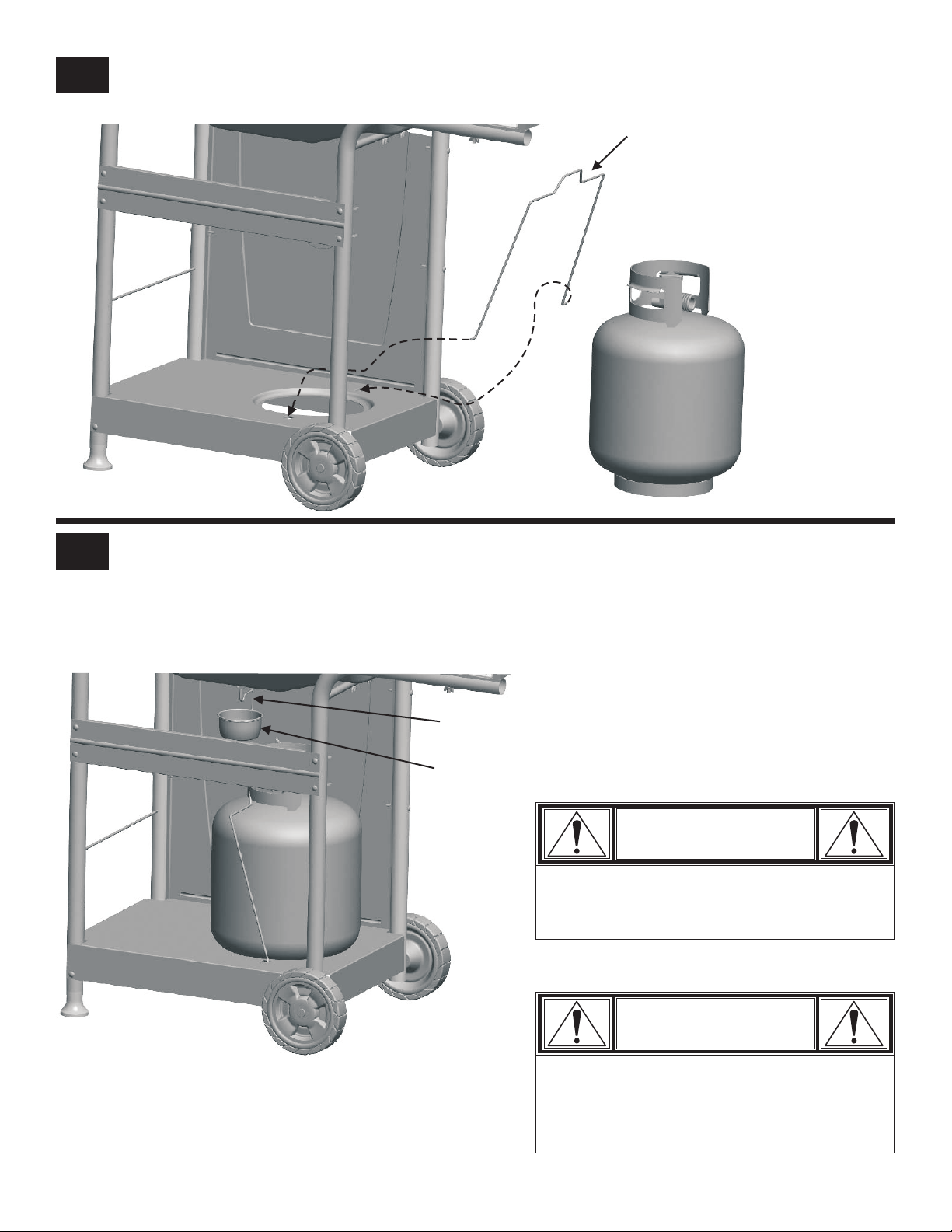
13
Insert tank wire into holes in bottom shelf of the cart.
Tank Wire
14
Hang grease cup clip from bottom of firebox and place grease cup into grease clip.
bottom of tank into bottom shelf. Rotate tank wire up to secure tank.
LP tank IS SOLD SEPARATELY. Fill and leak check the tank before attaching to grill and regulator (see Use & Care
Section). See Use & Care section of this manual to perform the "Burner Flame Check" and for important safety instructions
before using.
Grease Cup Clip
Grease Cup
Tank collar opening must face to left of grill. Set
CAUTION
Failure to install grease cup clip and cup will
cause hot grease to drip from bottom of grill
with risk of fire or property damage.
Always keep LP Tanks in
upright position during use,
transport, and storage
20 • 463821908
CAUTION
tank valve must face to front of cart once tank
is attached. Failure to install tank correctly
may allow gas hose to be damaged in
operation, resulting in the risk of fire.
Page 21
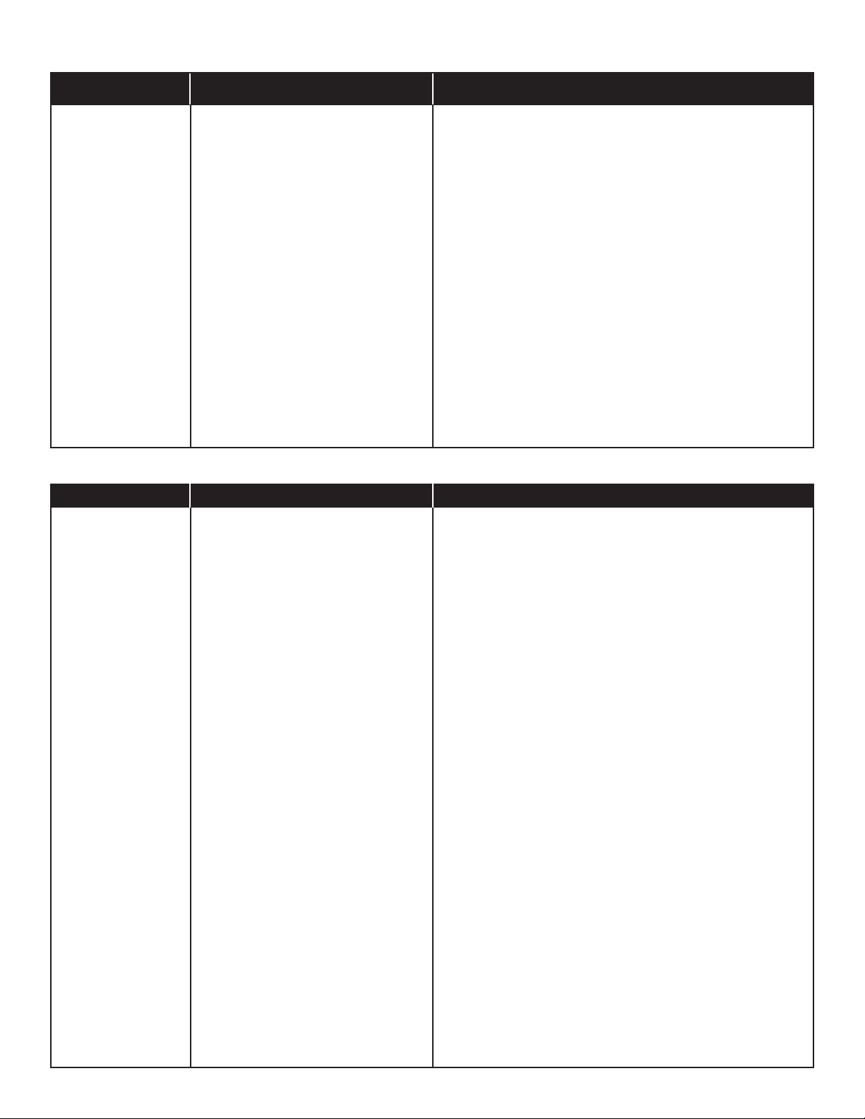
EMERGENCIES: If a gas leak cannot be stopped, or a fire occurs due to gas leakage, call the fire department.
Emergencies
Gas leaking from
cracked/cut/burned
hose.
Gas leaking from LP
tank.
Gas leaking from LP
tank valve.
Gas leaking between
LP tank and regulator
connection.
Fire coming through
control panel.
Grease fire or
continuous excessive
flames above cooking
surface.
Troubleshooting
Problem
Possible Cause
• Damaged hose.
• Mechanical failure due to rusting or
mishandling.
• Failure of tank valve from mishandling or
mechanical failure.
• Improper installation, connection not
tight, failure of rubber seal.
• Fire in burner tube section of burner due
to blockage.
• Too much grease buildup in burner area.
Possible Cause
Prevention/Solution
• Turn off gas at LP tank or at source on natural gas systems. If
anything but burned, replace valve/hose/regulator. If burned,
discontinue use of product until a plumber has investigated cause
and corrections are made.
• Replace LP tank.
• Turn off LP tank valve. Return LP tank to gas supplier.
• Turn off LP tank valve. Remove regulator from tank and visually
inspect rubber seal for damage. See LP tank Leak Test and
Connecting Regulator to the LP tank.
• Turn off control knobs and LP tank valve. Leave lid open to allow
flames to die down. After fire is out and grill is cold, remove burner
and inspect for spider nests or rust. See Natural Hazard and
Cleaning the Burner Assembly pages.
• Turn off control knobs and LP tank valve. Leave lid open to allow
flames to die down. After cooling, clean food particles and excess
grease from inside firebox area, grease cup, and other surfaces.
Prevention/Solution
Burner(s) will not light
using ignitor.
Continued on next
page.
GAS ISSUES:
• Trying to light wrong burner.
• Burner not engaged with control valve.
• Obstruction in burner.
• No gas flow.
• Vapor lock at coupling nut to LP tank.
• Coupling nut and LP tank valve not fully
connected.
ELECTRICAL ISSUES:
• Electrode cracked or broken; “sparks at
crack.”
• Electrode tip not in proper position.
• Wire and/or electrode covered with
cooking residue.
• See instructions on control panel and in Use and Care section.
• Make sure valves are positioned inside of burner tubes.
• Ensure burner tubes are not obstructed with spider webs or other
matter. See cleaning section of Use and Care.
• Make sure LP tank is not empty. If LP tank is not empty, refer to
“Sudden drop in gas flow.”
• Turn off knobs and disconnect coupling nut from LP tank.
Reconnect and retry.
• Turn the coupling nut approximately one-half to three-quarters
additional turn until solid stop. Tighten by hand only - do not use
tools.
• Replace electrode(s).
Main Burners:
• Tip of electrode should be pointing toward gas port opening on
burner. The distance should be 1/8” to 1/4”. Adjust if necessary.
Sideburner (if featured):
• Tip of electrode should be pointing toward gas port opening on
burner. the distance should be 1/8” to 3/16”. Adjust if necessary.
• Clean wire and/or electrode with rubbing alcohol and clean swab.
• Wires are loose or disconnected.
• Wires are shorting (sparking) between
ignitor and electrode.
• Reconnect wires or replace electrode/wire assembly.
• Replace ignitor wire/electrode assembly.
463821908 • 21
Page 22
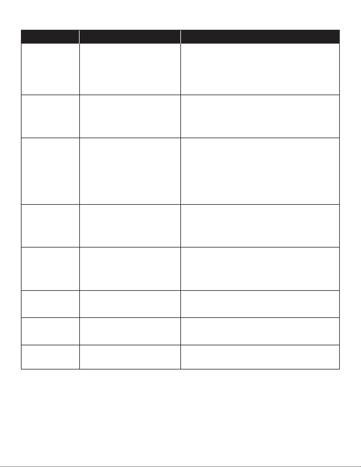
Troubleshooting (continued)
Problem
Burner(s) will not light
using ignitor.
Burner(s) will not
match light.
Low flame, drop in gas
flow.
Possible Cause
PIEZO PUSH-BUTTON AND ROTARY:
• Push-button sticks at bottom.
• Rotary knob rotates without clicking.
• Sparking between ignitor and electrode.
• See “GAS ISSUES:” on previous page.
• Match will not reach.
• Improper method of match-lighting.
• Out of gas.
• Excess flow valve tripped.
• Vapor lock at coupling nut/LP tank
connection.
Prevention/Solution
• Replace ignitor.
• Replace knob.
• Inspect wire insulation and proper connection. Replace wires if
insulation is broken.
• Use long-stem match (fireplace match).
• See “Match-Lighting” section of Use and Care.
• Check for gas in LP tank.
• Turn off control and tank knobs, wait 30 seconds, turn tank knob on
slowly, light grill. If flames are still low, turn off control and tank
knobs and disconnect regulator. Reconnect regulator, turn tank knob
on slowly, light grill.
• Turn off control and tank knobs and disconnect regulator. Reconnect
regulator, turn on tank knob slowly, light grill.
Flames blow out.
Flare-up.
Persistent grease fire.
Flashback...
(fire in burner tube(s)).
Unable to fill LP tank.
• High or gusting winds.
• Low on LP gas.
• Excess flow valve tripped.
• Grease buildup.
• Excessive fat in meat.
• Excessive cooking temperature.
• Grease trapped by food buildup around
burner system.
• Burner and/or burner tubes are blocked.
• Some dealers have older fill nozzles
with worn threads.
• Turn front of grill to face wind or increase flame height.
• Refill LP tank.
• Refer to “Sudden drop in gas flow” above.
• Clean burners and inside of grill/firebox.
• Trim fat from meat before grilling.
• Adjust (lower) temperature accordingly.
• Turn knobs to OFF. Turn gas off at LP tank. Leave lid in position and
let fire burn out. After grill cools, remove and clean all parts.
• Turn knobs to OFF. Clean burner and/or burner tubes. See burner
cleaning section of Use and Care.
• The worn nozzles don’t have enough “bite” to engage the valve. Try
a second LP dealer.
22 • 463821908
Page 23

LIMITED WARRANTY
Manufacturer warrants to the original consumer-purchaser only that this product shall be free from defects in workmanship and materials after
correct assembly and under normal and reasonable home use for the periods indicated below beginning on the date of purchase.
The manufacturer reserves the right to require that defective parts be returned, postage and or freight pre-paid, by the consumer, for review and
examination.
All Parts - 1 year
Upon consumer supplying proof of purchase as provided herein, Manufacturer will repair or replace the parts listed below which are proven
defective during the applicable warranty period. Parts required to complete such repair or replacement shall be free of charge to you except for
shipping costs. The original consumer-purchaser will be responsible for all shipping charges of parts replaced under the terms of this
limited warranty.
This limited warranty is applicable in the United States and Canada only, is only available to the original owner of the product and is not
transferable. Manufacturer requires reasonable proof of your date of purchase. Therefore, you should retain your sales slip or invoice and register
your new product immediately. Defective or missing parts subject to this limited warranty will not be replaced without registration or proof of purchase.
Register online at http://www.charbroil.com or complete and return via mail the Product Registration Card located on the last page of the Use & Care
manual included with this product and retain your sales receipt for proof of purchase.
This limited warranty applies to the functionality of the product ONLY and does not cover cosmetic issues such as scratches, dents, corrosions
or discoloring by heat, abrasive and chemical cleaners or any tools used in the assembly or installation of the appliance, surface rust, or the
discoloration of stainless steel surfaces.
This limited warranty will not reimburse you for the cost of any inconvenience, food, personal injury or property damage.
If an original replacement part is not available, a comparable replacement part will be sent. You will be responsible for all shipping charges of
parts replaced under the terms of this limited warranty.
ITEMS MANUFACTURER WILL NOT PAY FOR:
1. Service calls to your home.
2. Repairs when your product is used for other than normal, single-family household or residential use.
3. Damage resulting from accident, alteration, misuse, abuse, fire, flood, acts of God, improper installation, installation not in accordance with
electrical or plumbing codes, or use of products not approved by the manufacturer.
4. Any food loss due to product failures.
5. Replacement parts or repair labor costs for units operated outside the United States or Canada.
6. Pickup and delivery of your product.
7. Repairs to parts or systems resulting from unauthorized modifications made to the product.
8. The removal and/or reinstallation of your product.
9. Shipping cost, standard or expedited, for warranty and replacement parts.
DISCLAIMER OF IMPLIED WARRANTIES; LIMITATION OF REMEDIES
Repair or replacement of defect parts is your exclusive remedy under the terms of this limited warranty. Manufacturer will not be responsible for
any consequential or incidental damages arising from the breach of either this limited warranty or any applicable warranty, or for failure or damage
resulting from acts of God, improper care and maintenance, grease fire, accident, alteration,
replacement of parts by anyone other than Manufacturer, misuse, transportation, commercial use, abuse, hostile environments (inclement weather,
acts of nature, animal tampering), improper installation or installation not in accordance with local codes or printed manufacturer instructions.
THIS LIMITED WARRANTY IS THE SOLE EXPRESS WARRANTY GIVEN BY THE MANUFACTURER. NO PRODUCT PERFORMANCE
SPECIFICATION OR DESCRIPTION WHEREVER APPEARING IS WARRANTED BY MANUFACTURER EXCEPT TO THE EXTENT SET FORTH
IN THIS LIMITED WARRANTY. ANY IMPLIED WARRANTY PROTECTION ARISING UNDER THE LAWS OF ANY STATE, INCLUDING IMPLIED
WARRANTY OF MERCHANTABILITY OR FITNESS FOR A PARTICULAR PURPOSE OR USE, IS HEREBY LIMITED IN DURATION TO THE
DURATION OF THIS LIMITED WARRANTY.
Neither dealers nor the retail establishment selling this product has any authority to make any additional warranties or to promise
remedies in addition to or inconsistent with those stated above.
Manufacturer’s maximum liability, in any event, shall not exceed the documented purchase price of the product paid by the original consumer.
This warranty only applies to units purchased from an authorized retailer and or re-seller.
NOTE: Some states do not allow an exclusion or limitation of incidental or consequential damages, so some of the above limitations or
exclusions may not apply to you. This limited warranty gives you specific legal rights as set for herein. You may also have other rights which vary
from state to state. In the state of California only, if refinishing or replacement of the product is not commercially practicable, the retailer selling this
product or the Manufacturer will refund the purchase price paid for the product, less the amount directly attributable to use by the original consumerpurchaser prior to discovery of the nonconformity. In addition, in the state of California only, you may take the product to the retail establishment
selling this product in order to obtain performance under this limited warranty.
If you wish to obtain performance of any obligation under this limited warranty, you should write to:
Char-Broil Consumer Relations
P. O. Box 1240
Columbus, GA 31902-1240
Consumer returns will not be accepted unless a valid Return Authorization is first acquired by calling 1-800-241-7548 and then clearly marked
on the outside of the package and the package is shipped freight/postage pre-paid to the address above.
463821908 • 23
Page 24

Page
intentionally
blank
24 • 463821908
Page 25

Page
intentionally
blank
463821908 • 25
Page 26

Page
intentionally
blank
26 • 463821908
Page 27
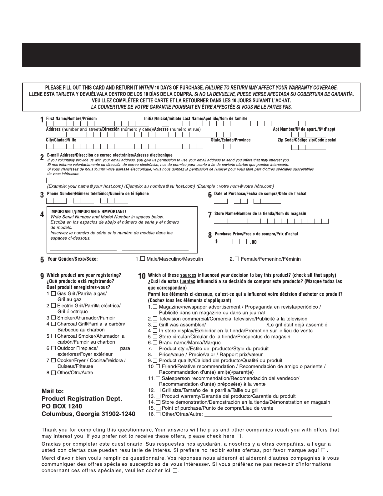
Please register your grill online at:
WWW.GRILLREGISTRATION.COM
(If you register online, you do not need to send in this registration card.)
/ Envíelo a:
La parrilla estaba ensamblada
Chimenea
463821908 • 27
Page 28

STOP
Should you encounter a problem with our product
CALL US FIRST
Do not return this product to the store.
WE CAN HELP
GRILL SERVICE CENTER
1-800-241-7548
HOURS 8AM-6PM EST Mon-Fri
Please ensure your warranty registration is complete.
Grilling Safety Checklist
Read and understand owners manual.
Never overfill LP tank. Overfilled tanks may cause freeze-up of
regulator.
Check tubes for spider webs. Ensure valves are correctly installed in
burner tubes.
Always ensure control knobs are in OFF position and regulator is
attached to tank BEFORE opening tank valve to avoid low flames.
Perform leak test regularly.
Thank You for Your Purchase!
Char-Broil, LLC Printed in China • Columbus, GA 31902 •
 Loading...