

Char-Broil 463278519, 463277519 Product Manual
PRODUCT GUIDE
GUíA DEL PRODUCTO
MEDALLION BUILT-IN GRILL
4 & 5 BURNER
MEDALLION PARRILLA INCORPORADA
4 y 5 QUEMADOR
463277519
MODEL
MODELO
SERIAL NUMBER
NÚMERO DE SERIE
• See rating label on grill for serial number.
• El número de serie se encuentra en la etiqueta
deespecificaciones de la parrilla.
DATE PURCHASED
FECHA DE COMPRA
NOTE: If you are planning to convert your grill from Natural Gas to Propane
Gas, it is highly recommended that you perform the conversion BEFORE grill
installation.
NOTA: Si planea convertir su parrilla de Gas Natural a Gas Propano, se
recomienda encarecidamente que realice la conversión ANTES de la instalación de la parrilla.
463277519
463278519
If you have questions or need assistance during assembly, please call 1-800-448-2177
Si tiene alguna pregunta o si Necesita ayuda durante el Ensamblado, llámenos Al 1-800-448-2177
9/13/18 • G622-001-010801
463278519
Easily converts from (NG) Natural Gas to (LP) liquid propane.
Se convierte fácilmente de (NG) gas natural a (LP) propano líquido.
CONVERSION KIT | KIT DE CONVERSION
#2429018
©
2018 Char-Broil, LLC. Columbus, GA, 31904. Printed in China. Imprimé en Chine. Impreso en China.
1
CONTENTS
IMPORTANT SAFETY
INFORMATION
IMPORTANT SAFETY INFORMATION PAGE 2
FOR YOUR SAFETY - INSTALLING YOUR GRILL. PAGE 3
PLANNING FOR INSTALLATION PAGE 4
LEAK CHECKING YOUR GRILL PAGE 7
FOR YOUR SAFETY - OPERATING YOUR GRILL PAGE 8
FOR YOUR SAFETY - LIGHTING YOUR GRILL PAGE 9
CARE AND MAINTENANCE OF GRILL PAGE 10
GRILL LIGHTS - OPERATION AND BULB REPLACEMENT PAGE 11
REPLACEMENT PARTS DIAGRAM - 463278519 PAGE 22
SAFETY SYMBOLS
DANGER, WARNING, and CAUTION statements are used throughout this Owner’s Manual
to emphasize critical and important information.
Read and follow these statements to help ensure
safety and prevent property damage.
The statements are defined below.
CAUTION
CAUTION: Indicates a potentially hazardous situation or unsafe
practice which, if not avoided, may result in minor or moderate
injury.
WARNING
WARNING: Indicates a potentially hazardous situation which, if
not avoided, could result in death or serious injury.
DANGER
DANGER: Indicates a imminently hazardous situation which, if
notavoided, will result in death or serious injury.
REPLACEMENT PARTS LIST - 463278519 PAGE 23
REPLACEMENT PARTS DIAGRAM - 463277519 PAGE 25
REPLACEMENT PARTS LIST - 463277519 PAGE 26
GRILL ASSEMBLY - 463278519 PAGE 28
GRILL ASSEMBLY - 463277519 PAGE 32
TROUBLESHOOTING PAGE 37
LIMITED WARRANTY PAGE 41
REGISTRATION CARD PAGE 43
DANGER
If you smell gas:
1. Shut off gas to the appliance
2. Extinguish any open flame.
3. Open lid.
4. If odor continues, keep away from the appliance and
immdiately call your gas supplier or your fire department.
WARNING
1. Do not store or use gasoline or other flammable liquids or
vapors in the vicinity of this or any other appliance.
2. An LP cylinder not connected for use shall not be stored in
the vicinity of this or any other appliance.
THIS GRILL IS FOR OUTDOOR USE ONLY
CHARBROIL.COMPage 2
FOR YOUR SAFETY - INSTALLING YOUR GRILL
WARNING
• Keep grill area clear and free from materials that
burn.
• Use grill only in well-ventilated space.
• NEVER use in enclosed space such as carport,
garage, porch, covered patio, or under an overhead combustible structure of any kind.
• Maintain 10 ft. clearance to objects that can
catch fire or sources of ignition such as pilot
lights on water heaters, live electrical appliances,
etc.
• Failure to follow all manufacturer’s instructions
could result in serious personal injury and/or
property damage.
• This outdoor gas appliance is not intended to be
installed in or on a boat or Recreational Vehicle.
• Never attempt to attach this grill to the self-contained LP gas system of a camper trailer or motor
home.
• Keep ventilation openings in cylinder enclosure
(grill cart) free and clear of debris.
• Use grill at least 3 feet (90 cm) from any wall
or surface.
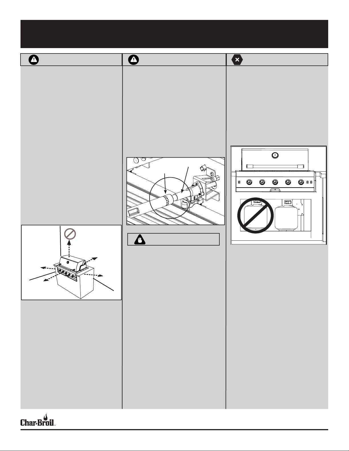
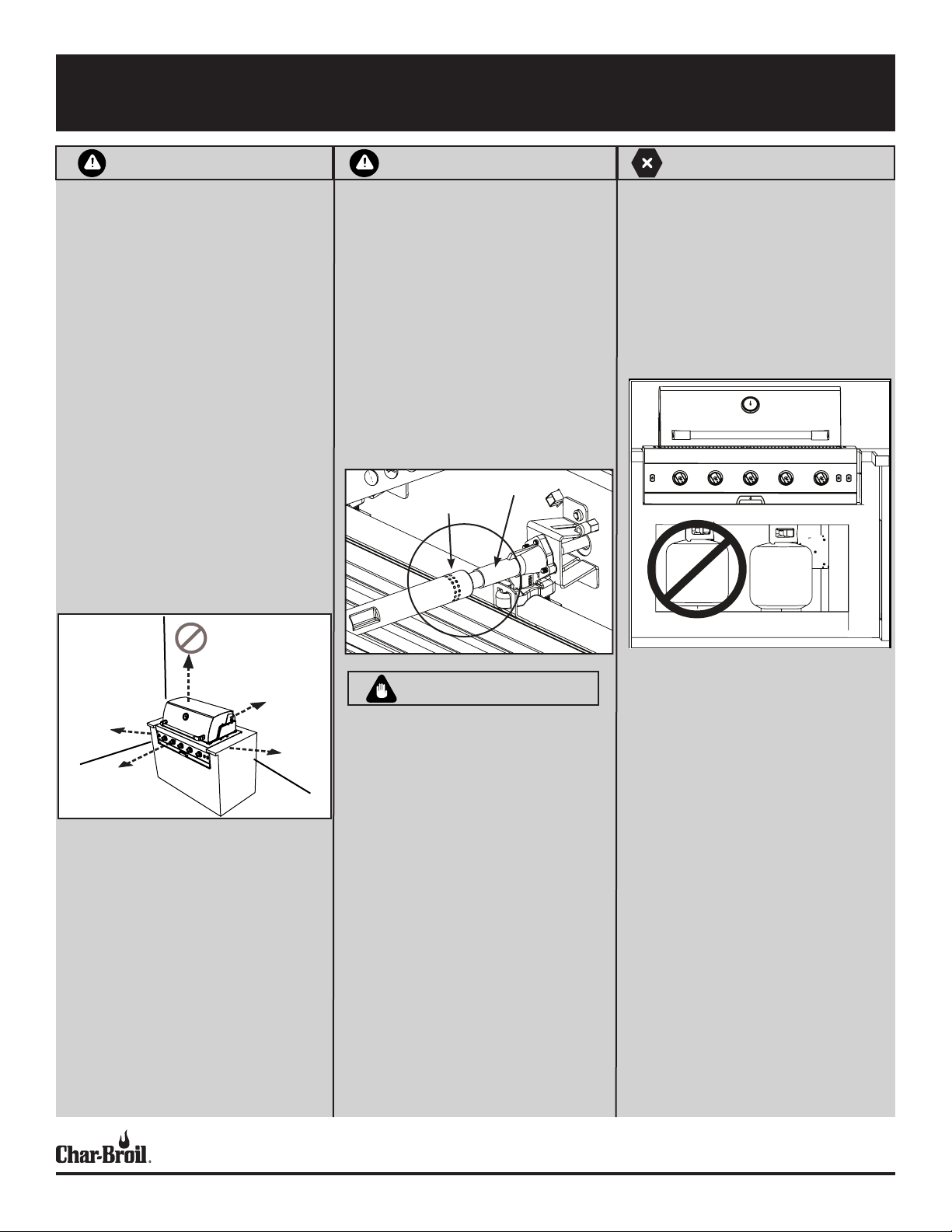
WARNING
Perform the following checks prior to the first
use of your grill:
• Make sure valves are inside the venturi tubes of
the burners as shown.
• Always ensure the control knobs pop up and lock
into the OFF position. Turn the tank valve on
PRIOR to turning on the control knobs to avoid
ignition problems and low flames.
• Perform a leak check as documented in the
“Leak Checking Your Grill” section.
• Check burner tubes for spider nests per the Care
and Mainentance of your Grill section.
Venturi
Valve
Tube
DANGER
• NEVER store a spare LP cylinder under or near
the appliance or in an enclosed area.
• An over filled or improperly stored cylinder is
a hazard due to possible gas release from the
safety relief valve. This could cause an intense
fire with risk of property damage, serious injury
or death.
• If you see, smell or hear gas escaping, immediately get away from the LP cylinder/appliance
and call your fire department.
36” (90CM)
36” (90CM)
KEEP AREA
ABOVE THE
GRILL CLEAR!
36” (90CM)
36” (90CM)
CAUTION
For residential use only. Do not use for commercial
cooking.
Read and follow all safety statements, assembly
instructions, and use and care directions before
attempting to assemble and cook.
Some parts may contain sharp edges. Wear protective gloves if necessary.
Installation Safety
Precautions
• Use grill, as purchased, only with Natural gas
and the regulator supplied. If your grill is Dual
Fuel ready, a conversion kit must be purchased
for use with LP (propane) gas.
• Grill installation must conform with local codes,
or in their absence of local codes, with either
the National Fuel Gas Code, ANSI Z223.1/ NFPA
54, Natural Gas and Propane Installation Code,
CSA B149.1, or Propane Storage and Handling
Code, B149.2.
• All electrical accessories (such as rotisserie)
must be electrically grounded in accordance
with local codes, or National Electrical Code,
ANSI / NFPA 70 or Canadian Electrical Code,
CSA C22.1. Keep any electrical cords and/or
fuel supply hoses away from any hot surfaces.
• This grill is safety certified for use in the United
States and/or Canada only. Do not modify for
use in any other location. Modification will
result in a safety hazard.
CHARBROIL.COMPage 3
PLANNING FOR INSTALLATION
LOCATION PLANNING
The following should be considered when determining where to place your new
built-in grill outdoor grill enclosure construction. It is best to identify the location
of the grill prior to beginning any set up.
• Plan for easy access to the house considering weather conditions like
frequent rain or snow that would make it more convenient to have the grill
located close to an entryway.
• Be sure to allow space for entertaining around the sides of the grill as it will
become a gathering area during outdoor events.
• Ventilation is a key to the grill’s performance and smoke exhaust should be
considered when identifying a location.
• The grill will smoke so consider the prevailing wind direction and position the
grill so wind blows toward the front of the grill to move the smoke away and
provide adequate airflow.
• Do not place the grill under or near windows that may be opened to your
house as smoke will enter easily.
Ensuring proper Combustion Air and Cooling Airflow
• Proper airflow MUST be maintained for the grill to perform as it was
designed. If airflow is blocked, overheating and poor combustion will result.
NOTE: Area directly beneath the grill must be open. No solid surface.
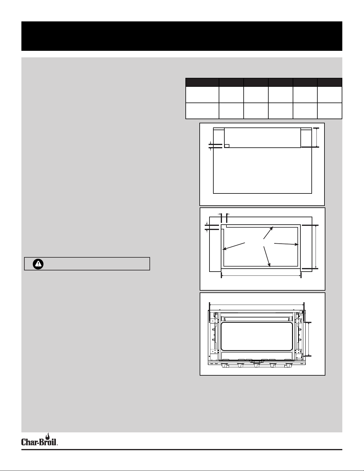
Grill Model Dim. A Dim. B Dim. C Dim. D Dim. E
463278519
4 Burner
463277519
5 Burner
34 7/8”
885mm
41.75”
1060mm
21.5/8”
548mm
21.5/8”
548mm
11”
279mm
11”
279mm
14 9/16”
370mm
14 9/16”
370mm
Dim. C
2.0” (50MM)
FRONT OF ENCLOSURE CUTOUT SHOWN
2.5” (63mm)
Dim. B
1” minimum
33 7/16”
848
40 5/16”
1023mm
GRILL INSTALLATION
WARNING
FOR LP GAS CONVERSION:
• Conversion to LP gas must be performed by a certified gas technician.
• LP Conversion Kit Model must be used. Specific details for enclosure
construction are included in the conversion kit instructions.
• Additional enclosure venting construction is required.
NOTE: ENCLOSURE MUST BE CONSTRUCTED OF NON-COMBUSTIBLE MATERIALS.
BUILDING THE ENCLOSURE:
• NOTE: If this grill is to be used as a replacement grill in an existing grill
enclosure, consult your local contractor to determine if the grill will work
correctly with your existing enclosure.
• Four “L” brackets are supplied for securing the grill to the enclosure.
• If grill enclosure design permits fastners only, four holes are provided on
bottom flange.
• Consult the table below for enclosure cut-out dimensions.
• The left rear corner of the enclosure must be open for gas connection
clearance. See Figures below.
1.75” (44mm)
Dim. A
TOP OF ENCLOSURE CUTOUT SHOWN
Dim. E
Dim. D
BOTTOM OF GRILL SHOWN
CHARBROIL.COMPage 4
PLANNING FOR INSTALLATION
If the grill is properly connected and still not getting gas, delivery pressure needs
to be verified. If pressure is greater than 1/2 psi, make sure that an in line regulator is present. Once the grill has been over-pressured, the regulator may or may
not have been damaged. The best practice is to replace the regulator.A natural gas
regulator rated at 4” water column is supplied with your grill. If you do not plan to
convert your grill to LP (propane) - This is the only regulator that should be used.
Note that this regulator can not be used for LP (propane)
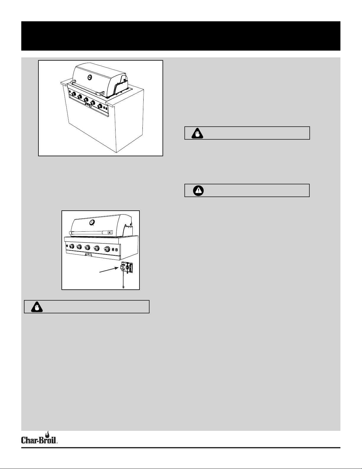
CAUTION
Grill shown installed in island
ELECTRONIC CONTROL MODULE:
NOTE: A licensed electrician should be used to install the ignition module and
make any wiring extensions or modifications.
• This grill has been supplied with 23” (60cm) of wire to mount the control
module in the right hand rear section of your grill enclosure. We recommend
that you mount the module to the rear wall of your enclosure.
MOUNT TO
REAR WALL
IMPORTANT
NATURAL GAS CONNECTIONS AND SERVICE REGULATORS ABOVE 1/2 PSI:
Prior to 1998, all residential gas service regulators were set with an outlet
pressure of 7 inches water column. In the 1998 edition of NFPA 54, the National
Fuel Gas Code, a change was made allowing service regulators of 2 and 5 psi.
With this change it was also required that an in line regulator be connected
between the service regulator and the appliance regulator if the 2 or 5 psi system
is used. This additional regulator is not supplied with the product. It is possible for
a consumer, making the connection themselves, or a plumber, not checking, to tap
into a 2 or 5 psi line. If a pressure of 2 psi or greater is supplied to the appliance
regulator on certain grills it will shut down and not deliver any gas to the grill. The
included quick disconnect socket and hose should not be used at pressures above
1/2 psi
The grill model 463278519 and model 463277519 are set for use with natural
gas. Both appliances are designed for conversion to LP gas also. CONVERSION
TO LP GAS MUST BE PERFORMED BY A CERTIFIED GAS TECHNICIAN. LP conversion kit model 2429018 must be used (sold separately).
WARNING
The outdoor grill must be disconnected from the natural gas supply piping system
during any pressure testing of the system in excess of ½ PSIG (3.5 kPa). The outdoor grill must be isolated from the natural gas supply piping system by closing
all individual shut-off valves during any pressure testing of the system equal to or
less than ½ PSIG (3.5 kPa). Never connect the grill to an unregulated gas supply.
CONNECTING THE NATURAL GAS SUPPLY LINE:
Step 1: Correctly Sizing the Natural Gas Supply Line
In most cases, a pipe diameter of ½” to ¾” is sufficient to connect your outdoor
grill to your home’s natural gas supply system. The correct pipe size depends on
the following:
1. The overall length of your home’s natural gas supply pipe run
2. The connection point of your outdoor grill into your home’s natural gas supply
system with respect to placement of natural gas appliances in your home
3. The desired distance of the outdoor grill from your home’s natural gas supply
4. The combined total BTU rate of all the natural gas appliances in your home.
A certified gas technician will be able to recommend the appropriate gas pipe size
and length to connect your outdoor grill to your home gas supply. The BTU rate of
the grill is 40,000 BTU/hr for model 463278519 and 45,000 BTU/hr for model
463277519.
Step 2: Placement of the Manual Shut-off Valve
It is recommended that a manual shut-off valve that is sized correctly for the
gas supply pipe be installed outside the grill enclosure. This valve will allow safe
access to shut off the natural gas supply to the built in grill in the event of an
emergency. A convenient location for the safety valve is at the rear of the grill
CHARBROIL.COMPage 5
PLANNING FOR INSTALLATION
enclosure. This allows for easy access to connect the gas piping in the enclosure
to the shut-off valve. If a gas supply stub-up is used inside the grill enclosure,
an external shut-off valve close to the grill is still recommended.
NOTE: A licensed plumber should be used to install the gas
supply line to the grill.
The gas supply line from your home should be routed to the left rear corner of
the grill inside the grill enclosure. It is recommended that hard piping be used to
connect to the inlet of the natural gas appliance regulator. Constant movement
of flexible gas lines could cause fatiguing of the flexible line and result in gas
leakage. If hard piping is not used for the home supply line, any flexible gas
lines must be supported within the enclosure to prevent constant movement and
fatiguing.
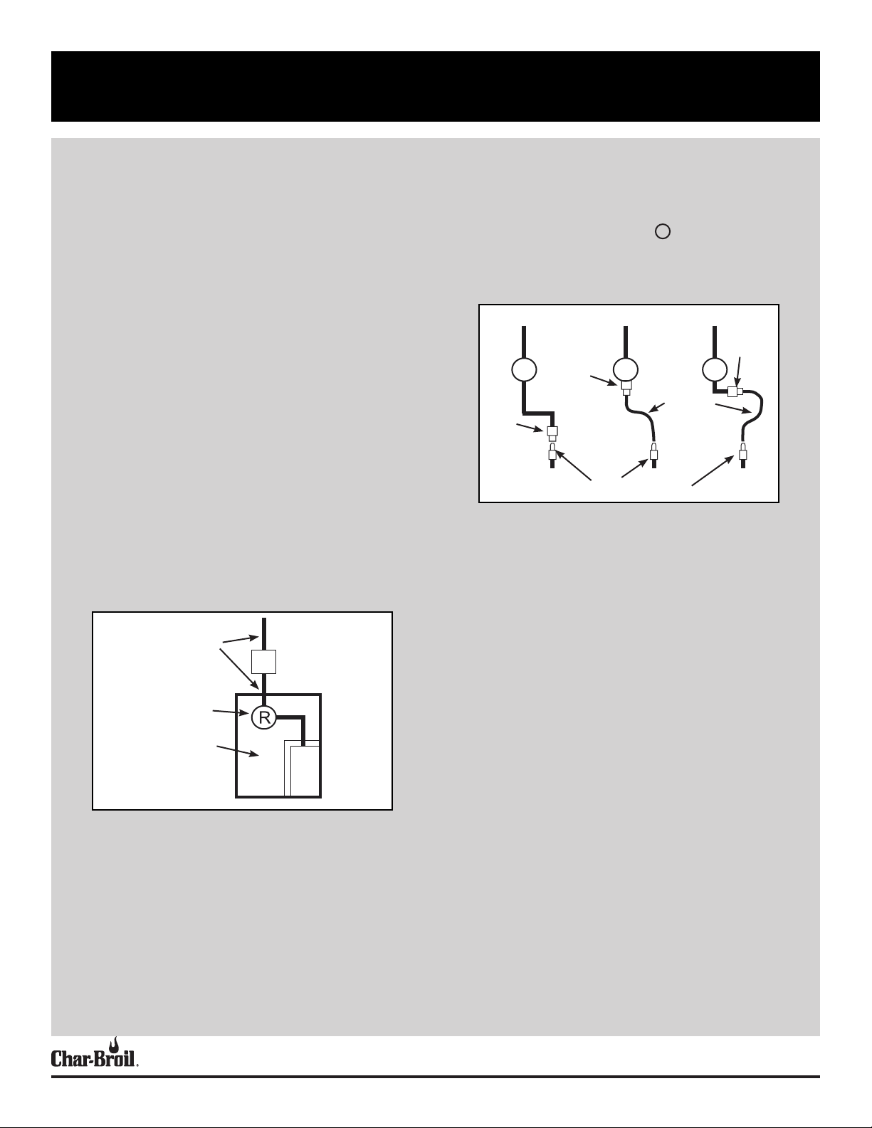
PRIOR TO INSTALLING THE GRILL IN THE ENCLOSURE:
1. Turn the home gas source to the OFF position.
2. Install the supplied 4 inch water column regulator to your hard piped,
natrual gas supply line. It is recommended that the regulator be located
inside the grill enclosure. The inlet and outlet sides fo the the regulator are
noted by markings on the regulator body. SEE FIGURE A.
3. The grill is now ready to be installed in the enclosure. Take care not to
damage the regulator during installation. Two persons are required to lift the
grill and place in the enclosure.
AFTER INSTALLING THE GRILL IN THE ENCLOSURE:
1. Use hard pipe with adapters or flexible tubing with adapters to connect the
outlet of the regulator to the grill’s 5/8” gas flare fitting. Adapters, fittings or
tubing are not supplied. See FIGURE B for piping suggestions.
2. Confirm all grill control knobs are turned to OFF.
3. Turn ON the home gas source.
4. Proceed to Leak Testing.
FIP to
Male flare
adapter
R RR
FIP to
Male flare
adapter
FIGURE B
MIP to
Male flare
adapter
Hose with
female flare
fittings
Male flare fitting at grill
FIGURE A
Gas In
Hard Pipe
Gas Shut off Valve
Regulator
Enclosure
Grill
CHARBROIL.COMPage 6
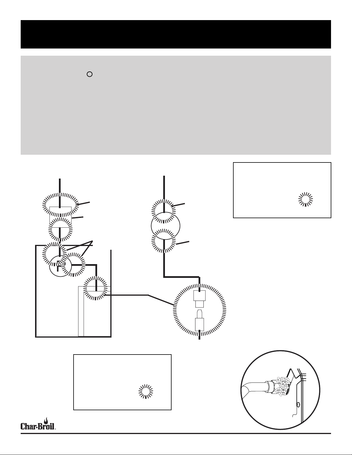
LEAK CHECKING YOUR GRILL
Leak Testing
1. Turn all grill control knobs to O FF.
2. Turn ON the home gas source.
3. Use a clean paint brush and a 50/50 mild soap and water solution. Brush soapy solution onto areas indicated. (see Figure C).
4. If “growing” bubbles appear, there is a leak. Close main gas supply and re-tighten all connections. If leaks cannot be stopped do not try to repair. Contact licensed
plumber for correction.
5. The appliance and its individual shut off valve must be disconnected from the gas supply piping system during any pressure testing on that system at test pressures in
excess of ½ psig (3.5kPa).
6. The appliance must be isolated from the gas supply piping system by closing its individual manual shut off valve during any pressure testing of the gas supply piping
system at test pressures equal to or less than ½ psig (3.5kPa).
7. IMPORTANT: You should leak check each piping connection.
IMPORTANT: You should leak
Gas Supply piping
Check for
leaks here
Check for
leaks here
check each piping connection.
Examples of possible locations
are shown here with a
Enclosure
FIGURE C
Gas Shut off Valve
Check for
leaks here
Check for
leaks here
Grill
IMPORTANT: You should leak
check each piping connection.
Examples of possible locations
Regulator
R
Check for
leaks here
Grill Connection
Example of “Growing” Bubbles
indicating a gas leak.
are shown here with a
CHARBROIL.COMPage 7
FOR YOUR SAFETY - WHILE OPERATING YOUR GRILL
WARNING
For Safe Use of Your Grill and to Avoid
Serious Injury:
• Controls and gas source or tank OFF when not
in use.
• Do not let children operate or play near grill.
• Check burner flames regularly.
• Do not use charcoal or ceramic briquets in a gas
grill.
• Do not cover grates with aluminum foil or any other
material. This will block burner ventilation and
create a potentially dangerous condition resulting
in property damage and/or personal injury.
• NEVER attempt to light or re-light burner with
lid closed. A buildup of non-ignited gas inside a
closed grill is hazardous.
DANGER
• If you see, smell or hear gas escaping, immediately
get away from the appliance and call your fire
department.
• If during operation the flames go out (You smell
gas or cannot see the flame):
1. Turn the burner controls OFF.
2. Open lid.
3. Wait 5 minutes and repeat the lighting
procedure.
• If the burner goes out, gas will continue to flow
out of the burner and could accidently ignite with
risk of injury.
• Do not attempt to repair or alter the natural gas
regulator for any “assumed” defect. Any modification to this assembly will void your warranty
and create the risk of a gas leak and fire. Use only
authorized replacement parts supplied by manufacturer.
CAUTION
• Putting out grease fires by closing the lid is not
possible. Grills are well ventilated for safety
reasons.
• Do not use water on a grease fire. Personal injury
may result. If a grease fire develops, turn knobs
and gas supply off.
• Do not leave grill unattended while preheating or
burning off food residue on HI. If grill has not been
regularly cleaned, a grease fire can occur that may
damage the product.
• The best way to prevent grease fires is regular
cleaning of the grill following instructions on
General Grill Cleaning and Cleaning The Burner
Assembly.
Before each use of your Grill:
Perform a Valve Check
• Important: Make sure gas is off at gas supply
before checking valves. Knobs lock in off posi-
tion. To check valves, first push in knobs and release,
knobs should spring back. If knobs do not spring
back, replace valve assembly before using grill. Turn
knobs to LOW position then turn back to off position.
Valves should turn smoothly.
Check the Ignitor
• Turn gas off at gas supply. Press and hold electronic
ignitor button. “Click” should be heard and spark
seen each time in each collector box or between
burner and electrode. See “Troubleshooting” if no
click or spark.
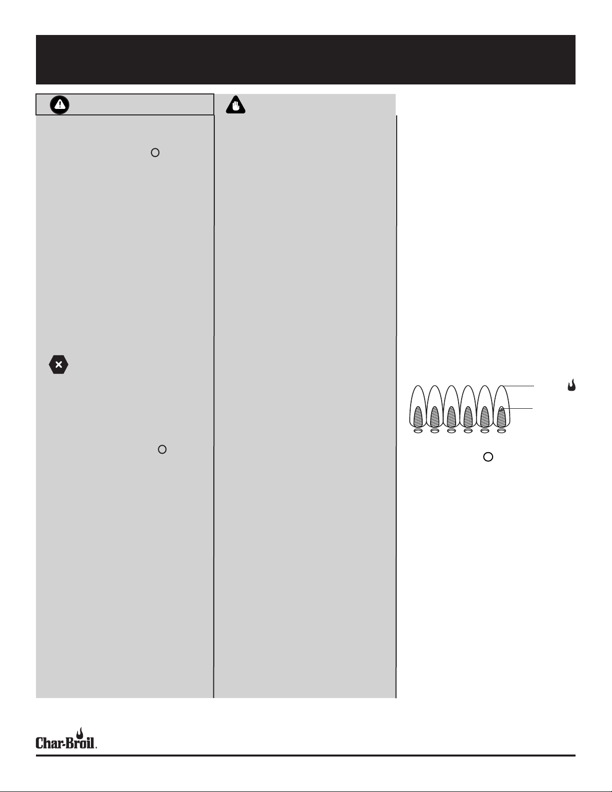
Burner Flame Check
• Remove cooking grates and heat tents. Light
burners, rotate knobs from HIGH to LOW. You should
see a smaller flame in LOW position than seen on
HIGH. Perform burner flame check on side burner,
also. Always check flame prior to each use. If only
low flame is seen refer to “Sudden drop or low
flame” in the Troubleshooting Section.
HIGH
LOW
Turning your Grill Off
• Turn all knobs to the OFF position. Turn gas
supply off by turning hand-wheel clockwise to a full
stop.
Checking the Fuel Gas Hose
• If you have converted your grill for use with LP
(propane) gas, check to see if hoses are cut, worn,
or kinked, Replace damaged hoses before using
your grill. Use only replacement hose specified by
the manufacturer.
CHARBROIL.COMPage 8
FOR YOUR SAFETY - LIGHTING YOUR GRILL
LIGHTING THE MAIN BURNERS
Main Burner Ignitor Lighting
• Do not lean over the grill while lighting.
1. Turn gas burner control valves to (OFF).
2. Open lid during lighting or re-lighting.
3. Turn ON gas at supply valve.
4. To ignite, push and turn burner knob to HIGH. Immediately, push and hold
ELECTRONIC IGNITOR button until the burner lights.
5. If ignition does NOT occur in 5 seconds, turn the burner controls OFF ,
wait 5 minutes and repeat the lighting procedure.
6. Repeat steps 4 and 5 to light other main burners.
Main Burner Match-Lighting
• Do not lean over the grill while lighting.
1. Turn gas burner control valves to (OFF).
2. Open lid during lighting or re-lighting.
3. Turn ON gas at supply valve.
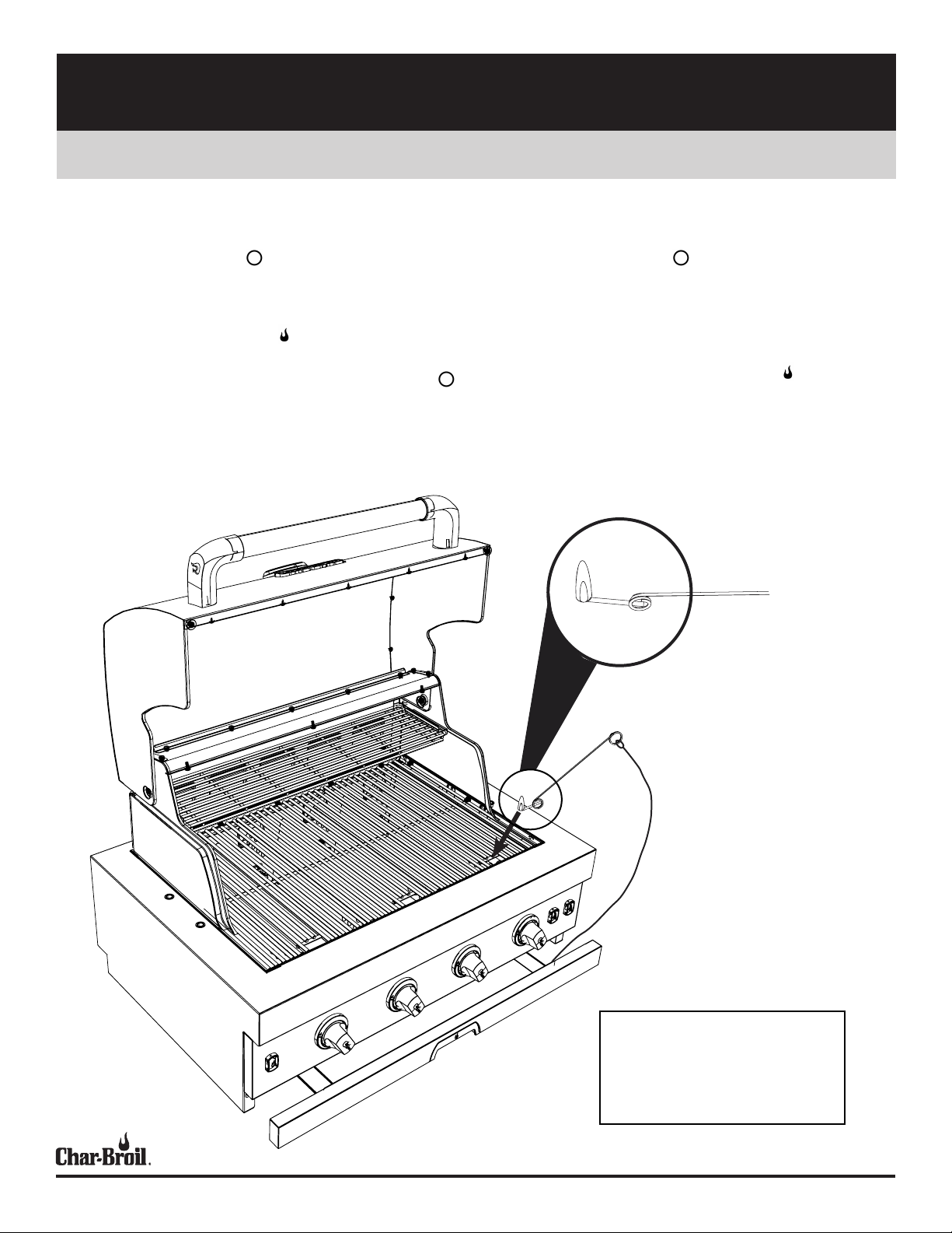
4. Place match into match holder (Located inside of grease tray). Light match;
then light burner by placing match through the rectangular hole in the cooking
grate. Immediately push in and turn burner knob to the HIGH position. Be
sure burner lights and stays lit.
5. Light adjacent burners in sequence by pushing knobs in and turning to the
HIGH position.
NOTE: 4 Burner Grill shown, follow the same
steps for the 5 Burner grill.
NOTA: Se muestra la parrilla de 4 quema-
dores, siga los mismos pasos para la parrilla
de 5 quemadores.
CHARBROIL.COMPage 9
CARE AND MAINTENANCE OF YOUR GRILL
Cleaning the Burner Assembly
Follow these instructions to clean and/or replace parts of burner assembly or if you
have trouble igniting griddle.
1. Turn gas off at control knobs and turn off gas at gas supply.
2. Remove griddle plate.
3. Remove hardware securing burners.
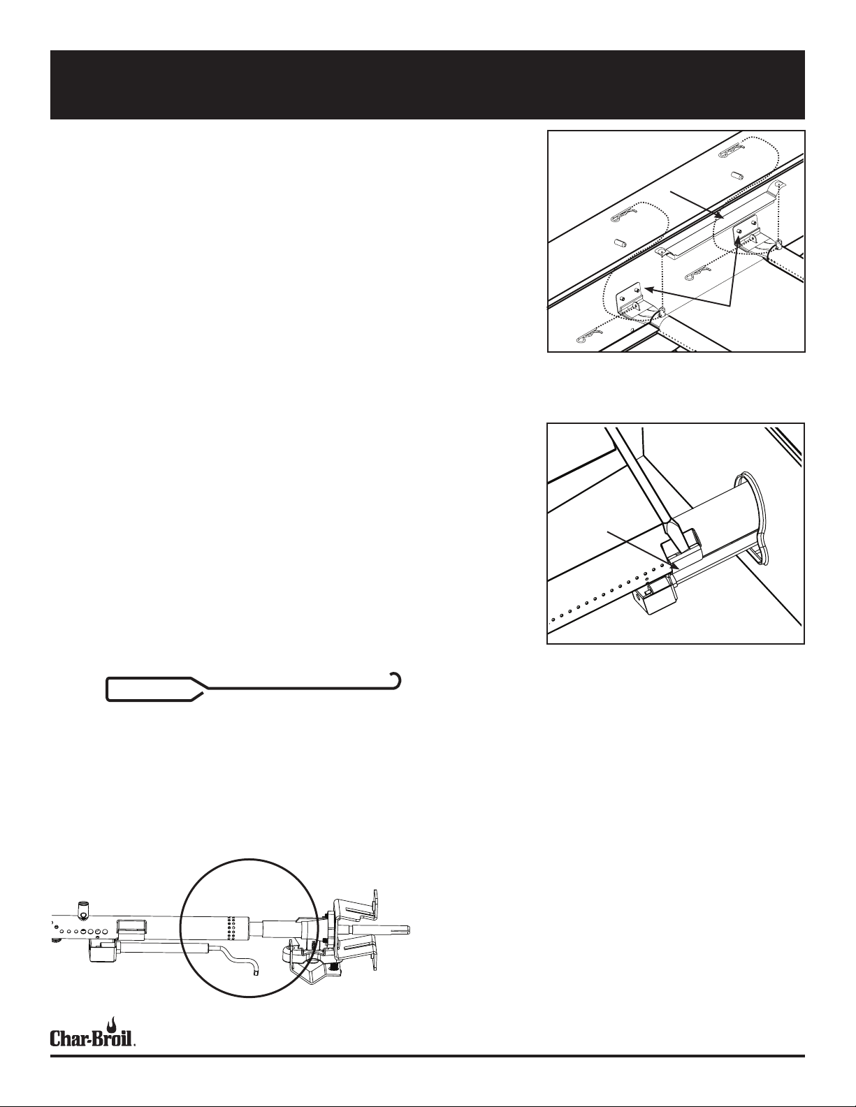
4. Remove Carryover tubes. Note that your grill’s carryover tubes may be located
at the front of the grill. Removal is the same, whther at the front or the rear.
5. Detach electrode from burner.
6. Carefully lift each burner up and away from valve openings.
We suggest three ways to clean the burner tubes. Use the one easiest for you.
• Bend a stiff wire (a light weight coat hanger works well) into a small
hook. Run the hook through each burner tube several times.
• Use a narrow bottle brush with a flexible handle (do not use a brass wire
brush). Run the brush through each burner tube several times.
• Wear eye protection: Use an air hose to force air into the burner tube
and out the burner ports. Check each port to make sure air comes out
each hole.
7. Wire brush entire outer surface of burner to remove food residue and dirt.
8. Clean any blocked ports with a stiff wire such as an open paper clip.
9. Check burner for damage due to normal wear and corrosion, some holes may
become enlarged. If any large cracks or holes are found, replace burner.
VERY IMPORTANT: Burner tubes must re-engage valve openings. See illustration below.
10. Attach electrode to burner.
11. Carefully replace burners.
12. Attach burners to brackets on firebox.
13. Reposition carryover tubes and attach to burners. Replace heat tents and cooking grates.
14. Before cooking again on griddle, perform a “Leak Test” and “Burner Flame
Check”.
FIREBOX
CARRYOVER TUBE
FIREBOX BURNER
SUPPORT
Electrode
Pry off electode with a
flat blade screwdriver.
STEP 5: Example of a bent, stiff
wire for cleaning your burner.
STEP 10: CORRECT BURNER
TO VALVE ENGAGEMENT
CHARBROIL.COMPage 10
GRILL LIGHTS - OPERATION AND BULB REPLACEMENT
Light Operation
• If your grill is hot, make sure the grill has been turned OFF and allowed to cool.
• Ensure the Grill Light Switch is in the OFF position.
• Connect the light plug to an extension cord, then put the extension cord plug into the wall
receptacle.
• Turn the light switch ON
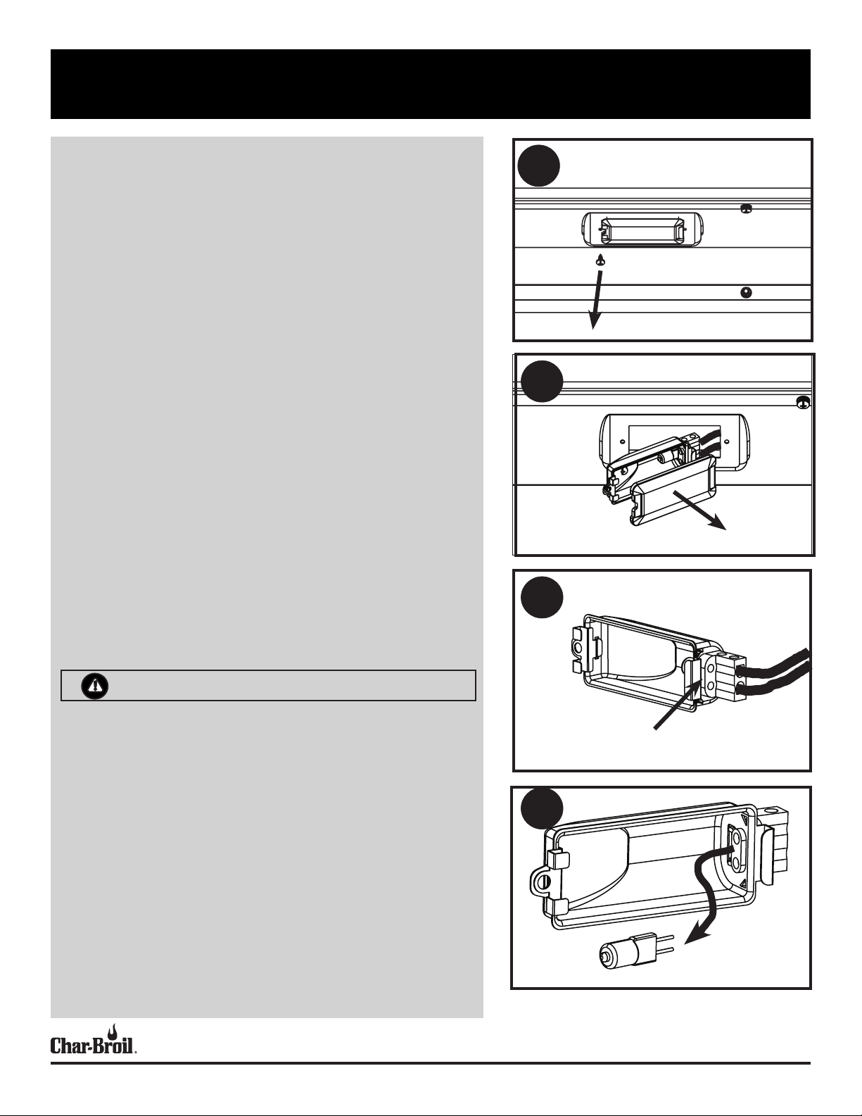
Bulb Replacement
• Make sure light switch on the control panel is in the OFF position and adapter plug is
disconnected from outlet.
1. Release the screw securing the light socket.
2. Take out the socket and remove the lens.
3. Loosen the two screws which are locking the bulb. NOTE: Skip step 3 if there is no screw
locking the bulb.
4. Pull out the old bulb.
5. Before handling the new bulb, put on a pair of cotton gloves. The oils from your hands can
damage or shorten the life of your new bulb.
6. Install the new bulb.
7. Reverse instructions from step 3 through step 1 to re-install socket.
Cleaning the Lens
1. Prior to cleaning, make sure grill has been turned off, cooled, and the light switch is in the
“OFF” position and the light plug is disconnected from the power supply.
2. Do not clean the glass lens when warm. Allow to cool before cleaning. Sudden change in
temperature may cause cracking of the glass lens.
3. Use a damp towel to clean the surface of the glass lens.
4. Allow the lens to dry before reconnecting the light plug to the power supply and turning the
light switch to the “ON” position.
1
2
3
WARNING
• Keep any electrical supply cord away from any heated surface.
• Use the shortest length extension cord required. Do not connect 2 or more extension cords
together.
• To protect against electric shock, do not immerse cord or plugs in water or other liquid.
• Unplug from the outlet when not in use and before cleaning. Allow to cool before putting on
or taking off parts.
• Do not operate grill with a damaged cord, plug, or after the appliance malfunctions or has
been damaged in any manner.
• Do not let the cord hang over the edge of a table or touch hot surfaces.
• Do not use an outdoor cooking gas appliance for purposes other than intended.
• When connecting, first connect plug to the outdoor cooking gas appliance then plug
appliance into the outlet.
• Use only a Ground Fault Interrupter(GFI) protected circuit with this outdoor cooking gas
appliance.
• Never remove the grounding plug or use with an adapter of 2 prongs.
• Use only extension cords with a 3 prong grounding plug, rated for the power of the equip-
ment, and approved for outdoor use with a W-A marking.
Loosen the two screws which
are locking the bulb, if needed.
4
Bulb Specification
Bulb Type: Halogen
Wattage: 10 Watts per bulb
Voltage: 12 V
CHARBROIL.COMPage 11
CONTENIDO
INFORMACIÓN IMPORTANTE
DE SEGURIDAD
INFORMACIÓN IMPORTANTE DE SEGURIDAD PÁGINA 12
PARA SU SEGURIDAD, INSTALACIÓN DE SU PARRILLA. PÁGINA 13
PLANIFICACIÓN PARA LA INSTALACIÓN PÁGINA 14
CONTROLAR LAS FUGAS DE SU PARRILLA PÁGINA 17
PARA SU SEGURIDAD, OPERAR SU PARRILLA PÁGINA 18
PARA SU SEGURIDAD, ENCENDER SU PARRILLA PÁGINA 19
CUIDADO Y MANTENIMIENTO DE SU PARRILLA PÁGINA 20
LUCES DE LA PARRILLA - FUNCIONAMIENTO Y SUSTITUCIÓN DE BOMBI-
LLAS PÁGINA 21
DIAGRAMA DE PIEZAS DE REPUESTO - 463278519 PÁGINA 22
SÍMBOLOS DE SEGURIDAD
Las indicaciones de PELIGRO, ADVERTENCIA y
PRECAUCIÓN se utilizan a lo largo de este Manual
del propietario para enfatizar información crítica e
importante. Lea y siga estas indicaciones para ayudar a
garantizar la seguridad y evitar daños a la propiedad.
Las indicaciones se definen a continuación.
PRECAUCIÓN
PRECAUCIÓN: Indica una situación potencialmente peligrosa o práctica insegura que, si no se evita, puede dar como resultado una lesión
menor o moderada.
ADVERTENCIA
ADVERTENCIA: Indica una situación potencialmente peligrosa que, si
no se evita, podría provocar la muerte o lesiones graves.
PELIGRO
PELIGRO: Indica una situación inminentemente peligrosa que, si no
se evita, ocasionará la muerte o lesiones graves.
LISTA DE PIEZAS DE REPUESTO - 463278519 PÁGINA 24
DIAGRAMA DE PIEZAS DE REPUESTO PÁGINA 25
LISTA DE PIEZAS DE REPUESTO - 463277519 PÁGINA 27
MONTAJE DE LA PARRILLA - 463278519 PÁGINA 28
MONTAJE DE LA PARRILLA - 463277519 PÁGINA 32
SOLUCIÓN DE PROBLEMAS PÁGINA 39
GARANTÍA LIMITADA PÁGINA 41
TARJETA DE REGISTRO PÁGINA 43
ESTA PARRILLA ES SOLO PARA USO EN EXTERIORES
PELIGRO
Si huele a gas:
1. Cierre el suministro de gas al aparato
2. Extinga cualquier llama abierta.
3. Abra la tapa.
4 Si el olor continúa, manténgase alejado del aparato y llame
inmediatamente a su proveedor de gas o a su departamento de
bomberos.
ADVERTENCIA
1. No almacene ni use gasolina u otros líquidos o vapores inflamables
cerca de este o cualquier otro aparato.
2. Un cilindro de LP no conectado para su uso no debe almacenarse
cerca de este ni de ningún otro aparato.
CHARBROIL.COMPágina 12
PARA SU SEGURIDAD, INSTALACIÓN DE SU PARRILLA
ADVERTENCIA
• Mantenga el área de la parrilla despejada y libre de
materiales que se quemen.
• Use la parrilla solo en espacios bien ventilados.
• NUNCA la use en espacios cerrados tales como
garaje, garaje, porche, patio cubierto o debajo de una
estructura combustible superior de ningún tipo.
• Mantenga un espacio libre de 10 pies sobre los objetos
que puedan incendiarse o sobre las fuentes de ignición, como luces piloto en los calentadores de agua,
electrodomésticos, etc.
• El incumplimiento de todas las instrucciones del fabricante podría ocasionar lesiones personales graves y/o
daños a la propiedad.
• Este aparato de gas para exteriores no está diseñado
para instalarse sobre o dentro de un bote o vehículo
recreativo.
• Nunca intente conectar esta parrilla al sistema autónomo de gas LP de un remolque o autocaravana.
• Mantenga las aberturas de ventilación en el recinto del
cilindro (carro de la parrilla) libres de residuos.
• Use la parrilla por lo menos a 3 pies (90 cm) de cualquier pared o superficie.
¡MANTENGA
LIBRE EL ÁREA
POR ENCIMA DE
LA PARRILLA!
36” (90CM)
36” (90CM)
36” (90CM)
36” (90CM)
ADVERTENCIA
Realice las siguientes verificaciones antes del primer
uso de su parrilla:
• Asegúrese de que las válvulas estén dentro de los
tubos venturi de los quemadores, como se muestra.
• Asegúrese siempre de que las perillas de control
se abren y se bloquean en la posición de OFF
(APAGADO). Encienda la válvula del tanque ANTES de
encender las perillas de control para evitar problemas
de encendido y llamas bajas.
• Realice una comprobación de fugas tal como se documenta en la sección "Comprobación de fugas en la
parrilla".
• Verifique los tubos del quemador en busca de nidos de
arañas siguiendo la sección de Cuidado y manteni-
miento de su parrilla.
Tubo
Válvula
venturi
PRECAUCIÓN
Solo para uso residencial. No usar para cocina comercial.
Lea y siga todas las declaraciones de seguridad, las instrucciones de montaje, y las instrucciones de uso y cuidado
antes de intentar armar y cocinar.
Algunas partes podrían contener bordes filosos. Use
guantes protectores si es necesario.
PELIGRO
• NUNCA almacene un cilindro de LP de repuesto
debajo o cerca del aparato o en un área cerrada.
• Un cilindro llenado en exceso o almacenado incorrectamente es un peligro debido a la posible liberación de gas de la válvula de alivio de seguridad.
Esto podría causar un incendio intenso con riesgo
de daños a la propiedad, lesiones graves o la muerte.
• Si ve, huele o escucha un escape de gas, aléjese
inmediatamente del cilindro de LP/aparato y llame
a su departamento de bomberos.
•
Precauciones de seguridad de instalación
• Use la parrilla, tal como se compró, solo con gas
natural y el regulador suministrado. Si su parrilla
está preparada para usar combustible dual, se debe
comprar un kit de conversión para usar con gas LP
(propano).
• La instalación de la parrilla debe cumplir con los
códigos locales, o en ausencia de códigos locales,
ya sea con el Código Nacional de Gas Combustible,
ANSI Z223.1/ NFPA 54, Código de Instalación de Gas
Natural y Propano, CSA B149.1 o Código de Almacenamiento y Manipulación de Propano, B149.2.
• Todos los accesorios eléctricos (como el asador)
deben conectarse a tierra de acuerdo con los códigos
locales o el Código Eléctrico Nacional, ANSI / NFPA
70 o el Código Eléctrico Canadiense, CSA C22.1.
Mantenga los cables eléctricos y/o las mangueras
de suministro de combustible lejos de las superficies
calientes.
• Esta parrilla está certificada de seguridad para su
uso en los Estados Unidos y/o Canadá solamente. No
la modifique para usarla en ninguna otra ubicación.
La modificación dará como resultado un riesgo de
seguridad.
CHARBROIL.COMPágina 13

PLANIFICACIÓN PARA LA INSTALACIÓN
PLANIFICACIÓN DE LA UBICACIÓN
NOTA: El área directamente debajo de la parrilla debe estar abierta. Sin superficie sólida.
Se debe considerar lo siguiente al determinar dónde colocar su nueva para parrilla al
aire libre. Lo mejor es identificar la ubicación de la parrilla antes de comenzar cualquier
preparación.
• Planifique un acceso fácil a la casa teniendo en cuenta las condiciones climáticas,
como las frecuentes lluvias o nieve, que harían más conveniente tener la parrilla
ubicada cerca de una entrada.
• Asegúrese de dejar espacio para el entretenimiento a los lados de la parrilla, ya que
se convertirá en un área de reunión durante los eventos al aire libre.
• La ventilación es una clave para el rendimiento de la parrilla y se debe considerar el
escape de humo al identificar una ubicación.
• La parrilla humeará, así que tenga en cuenta la dirección predominante del viento y
coloque la parrilla de modo que el viento sople hacia la parte delantera de la parrilla
para alejar el humo y proporcionar un flujo de aire adecuado.
• No coloque la parrilla debajo o cerca de ventanas que puedan abrirse en su casa ya
que el humo entrará fácilmente.
Asegurando un flujo de aire de combustión y enfriamiento adecuados
• Un flujo de aire apropiado DEBE mantenerse para que la parrilla funcione tal como
fue diseñada. Si el flujo de aire está bloqueado, se producirá un sobrecalentamiento
y una combustión deficiente.
Modelo de parrilla Dim. A Dim. B Dim. C Dim. D Dim. E
463278519
4 quemadores
463277519
5 Burner
34 7/8”
885mm
41.75”
1060mm
21.5/8”
548mm
21.5/8”
548mm
11”
279mm
11”
279mm
14 9/16”
370mm
14 9/16”
370mm
33 7/16”
848
40 5/16”
1023mm
2.0” (50MM)
Dim. C
SE MUESTRA UNA VISTA DE RECORTE DE LA PARTE DELANTERA DEL
RECINTO
2.5” (63mm)
Dim. B
INSTALACIÓN DE LA PARRILLA
ADVERTENCIA
PARA LA CONVERSIÓN DE GAS LP:
• La conversión a gas LP debe ser realizada por un técnico de gas certificado.
• Se debe usar el modelo de kit de conversión LP. Los detalles específicos para la
construcción del recinto se incluyen en las instrucciones del kit de conversión.
• Se requiere una construcción adicional de ventilación del recinto.
NOTA: EL RECINTO DEBE ESTAR CONSTRUIDO DE MATERIALES NO
COMBUSTIBLES.
CONSTRUCCIÓN DEL RECINTO:
• NOTA: Si esta parrilla se va a utilizar como parrilla de reemplazo en un recinto
de parrilla existente, consulte a su contratista local para determinar si la parrilla
funcionará correctamente con su recinto existente.
• Se suministran cuatro soportes en "L" para asegurar la parrilla al recinto.
• Si el diseño del resisto de la parrilla solo permite sujetadores, se proporcionan cuatro
orificios en la brida inferior.
• Consulte la tabla a continuación para ver las dimensiones de corte del recinto.
• La esquina trasera izquierda del gabinete debe estar abierta para la separación de la
conexión de gas. Consulte las Figuras a continuación.
1.75” (44mm)
Dim. A
SE MUESTRA UNA VISTA DE RECORTE DE LA PARTE SUPERIOR DEL
RECINTO
Dim. E
Dim. D
SE MUESTRA LA PARTE INFERIOR DE LA PARRILLA
CHARBROIL.COMPágina 14
 Loading...