

Page 1
Assembly
Guide
Model Numbers:
08401504-A1
08401504-A2
08401504
10401582
10401589
10401590
10401591
10401592
10401593
10401594
12401504
12401590
GAS (LP)
(English)
42804526 • 8/16/2011
Page 2
2
ASSEMBLY GUIDE
A, B, C, Assembly:
CAUTION: For your safety, before operating, Read Product Guide & Outdoor Cooking Guide
provided with this grill.
*SAFETY First…..Grill components may have sharp edges. Be careful when handling grill parts
during assembly. We suggest that you wear a sturdy pair of leather gloves while handling the grill parts.
BEFORE You begin assembly of your grill….
1. Carefully remove all components from the carton.
2. Familiarize yourself with the components and hardware used for assembly.
3. Please note that hardware used for assembly may not be shown actual size..
4. After removing components from the carton, split the carton open and use it as
a scratch-free work pad to assemble your grill.
BEFORE You Grill….
1. Read Product Guide & Outdoor Cooking Guide
2. Position Grill safely away from walls & structures
3. Pre– Heat Grill—15 minutes on High to season grill.
NOTE….
Installer: Leave instructions with the grill.
Consumer: Retain instructions for reference.
Grill must be installed in accordance with local
codes…..
Designed for outdoor use on ly…
Read all instructions before operating…
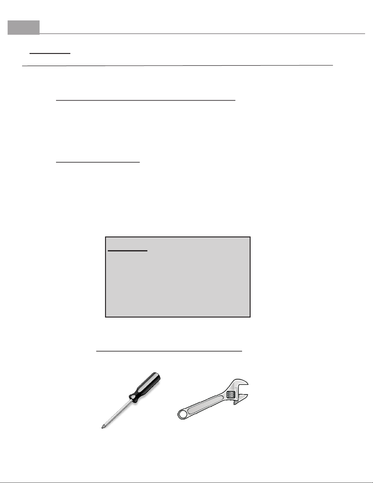
TOOLS REQUIRED FOR ASSEMBLY
(Not Supplied)
Phillips Head
Screwdriver
Small Adjustable
Wrench
Page 3
3
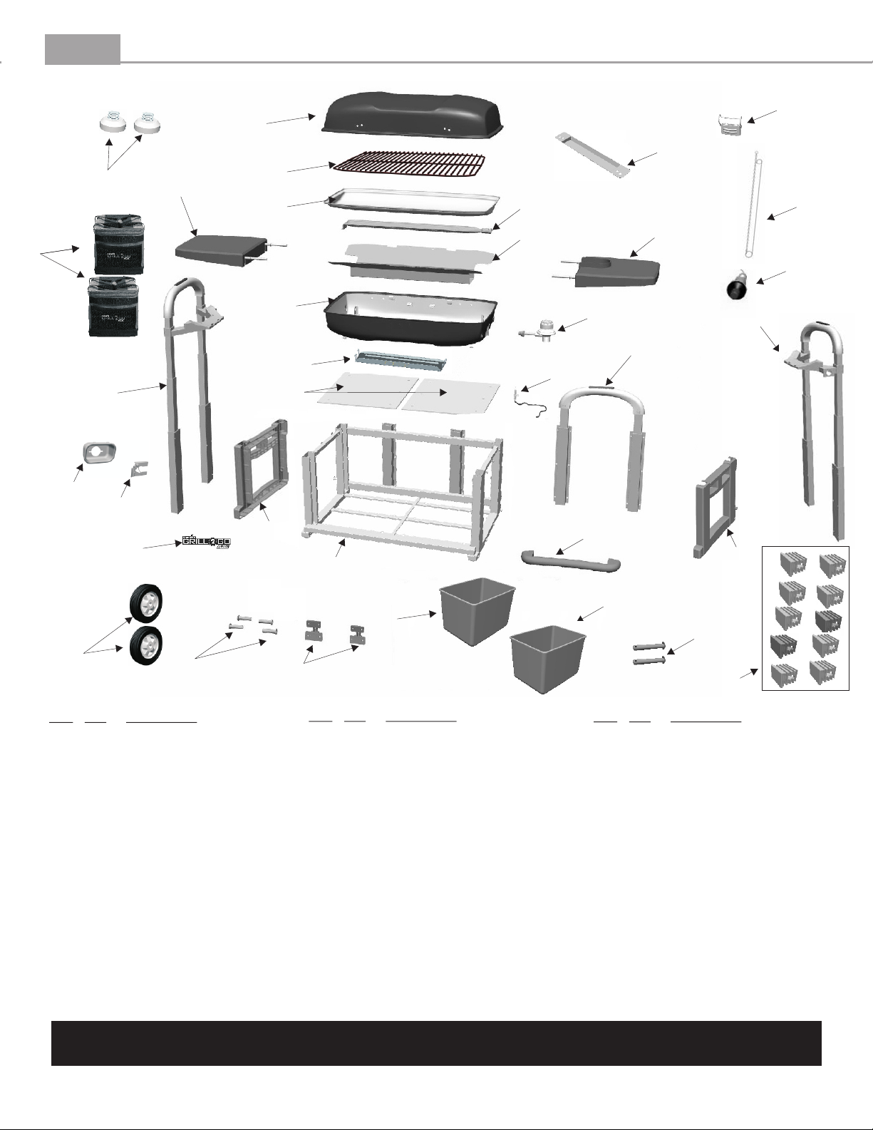
ASSEMBLY GUIDE
Grill Parts Diagram
A
BB
AA
CC
J
B
C
D
E
K
Y
TT
FF
F
L
H
I
G
R
H
Z
EE
O
W
P
Q
V
GG
GG
U
M
Key Qty Description
A 1 Grill Lid
B 1 Cooking Grate
C 1 Trough
D 1 Burner
E 1
F 1 Firebox Bottom
G 1 Heat Shield
H 2 Side Lift Mechanism
I 1 Rear Lift Mechanism
J 1 Left Side Shelf
K 1 Right Side Shelf
L 1 Regulator Control Valve
M 2 Wheel
Inner Reflector
S
N
Key Qty Description
N 1 Hinge Set
O 1
P 1 Handle
Q 1 Logo Plate
R 1 Electrode with Wire
S 2 Side Shelf Bushings
T 2 Cooler Bag
U 2 Axle Rod
V 1 Cart Base
W 1 LH Cart Fascia
X. 1 RH Cart Fascia
Y 1 Match Holder
Z 2 Cooler Tray Kit
Venturi Latch Assembly
Key Qty Description
AA 1 Handle Heat Sheild
BB 1 Lid Clasp
CC 2 Cart Foot
DD 10 Tube Plug
EE 1 Venturi Guard
FF 1 Piezo Ignitor Button
GG 2 Cooler Liner
... 1 Hardware Pack
... 1 Assembly Manual, English
... 1 Assembly Manual, Spanish
1 Assembly Manual, French
...
1 Product Guide, English
...
... 1 Product Guide, Spanish
... 1 Product Guide, French
NOTE: Some grill parts shown in the assembly steps may differ slightly in appearance from
those on your particular model. However, the method of assembly remains the same.
X
DD
Page 4

4
ASSEMBLY GUIDE
Part Qty
A1–
–
A2
– Cart Base 1
A3
–
A4
–
A5
Cart RH Side Fascia
Cart LH Side Fascia
Cart Foot
Wheels
1
1
2
2
GRILL CART Assembly
Fasteners
#10x3/4"
screw
(qty 14)
Wheel Retaining
Clip
(qty 2)
Axle Rod
(qty 2)
Step 1: Assemble the LH and RH Side Fascia (A1 & A2)
to the Cart Base (A3) by aligning screw holes in the
fascias with corresponding holes in the cart base.
Secure with 7 each, #10x3/4 screws (7 per side) using a
phillips screwdriver. Repeat for other side. NOTE: The
lift handles are shown in the up position. You can
complete steps 1 and 2 with the handles lowered if
desired.
A1
A2
A3
Step 2: Carefully place the cart assembly on its
back. Install the Cart Feet (A4) by
threading them into the bushings as shown.
Securely tighten the cart feet.
A4
A3
Step 3: Assemble the Wheels (A5) to the Cart Base
(A3) by first sliding an axle rod through the wheel,
then sliding the axle rod through the axle rod holes
in the cart base. Secure with a wheel retaining clip.
Repeat for the other side.
Axle Hole
A5
Axle Rod
A3
Wheel Retaining Clip - install after
placing wheel and axle rod through
axle hole.
Clip shown properly installed.
Wheel retaining clip Install after wheel and axle rod
through the hole as shown in
this direction only.
Page 5

5
ASSEMBLY GUIDE
–
B1
–
B2
Part Qty
Heat Shield
Fire Box Assembly
GRILL Assembly
1
1
Fasteners
Note: Before beginning this step of the
assembly, raise the two side lifts to their
highest position by pressing the button at the
top of the handle and pulling upward on the
handle.
The pull handle at the rear of the cart also has
a locking button, press the button to raise or
lower the pull handle into the desired
position. During Assembly, the rear pull
handle should remain in its lowered position.
#10-24 x 1 1/4"
screw
(qty 4)
Firebox Mounting Brackets
B1
FRONT
#10-24
nut
(qty 4)
#10 Lock
washer
(qty 4)
Fiber Washer
(qty 4)
Step 1 - Install the Heat Shield(B1) to
the firebox mounting brackets by
engaging the tabs into the slots located
in the mounting brackets as shown on
the right.
Rear Pull Handle
Pull Handle Locking Button
Assure FRONT marking on Heat Shield is to the front of the grill.
Step 2 - Install the Fire Box Assembly(B2) to the cart by first placing the firebox assembly onto the
firebox mounting brackets. Be sure that the lid clasp is toward the front of the cart. Align the firebox
screw holes with the corresponding holes in the mounting brackets. Insert 4 #10-24 x 1 1/4" machine screws
and 4 fiber washers through the firebox and mounting brackets. Secure with 4 #10-24 nuts and 4 #10
lock washers from below the mounting brackets as shown below.
#10-24 x 1 1/4"
machine screws
Fiber washers
FRONT
#10 lock washers
#10-24 nuts
B2
Right hand side
Firebox screw
holes
NOTE: As viewed
from the front of
the grill.
NOTE: As viewed
from the front of
the grill.
Left hand side
Firebox screw
holes
Page 6

6
ASSEMBLY GUIDE
Part Qty
B3– Hinge, RH 1
B4– Hinge, LH 1
B5– Grill Lid 1
B6– Heat Shield 1
B7– Handle 1
ASSEMBLY
Step 3 - Attach the Hinges (LH and RH) (B4 & B3) to the
Firebox Bottom by aligning the screw holes on the bottom of
the grill with the corresponding holes in the hinges. Secure
with 2 each #10-24x5/8" screws, 2 fiber washers and 2 #10-24
nuts as shown.
NOTE: The LH hinge is mounted to the left side
of the firebox bottom as viewed from the rear of
the firebox. See Hinge Detail below.
B4
10-24 x 5/8"
GRILL Assembly
Fasteners
screw
(qty 12)
Fiber Washer
(qty 8)
10-24 Nut
(qty 8)
Step 4 - Attach the Grill Lid (B5) to the Hinges by
aligning the screw holes on the grill lid with the
corresponding holes in the hinges. Secure with 2 each #10-
24x5/8" screws, 1 spacer and 2 #10-24 nuts as shown.
B5
Spacer for Lid
(qty 2)
LH Hinge
View from rear of firebox
B2
LH side shown,
RH side similar.
Step 5 - Attach the Heatshield (B6) and Handle (B7) the
Grill Lid (B5) by aligning the screw holes in the handle to and
heatshield with the corresponding holes in the Grill Lid.
Loosely install 1 10-24 x 5/8" Screw and 1 fiber washer on the
LH side of handle. Loosely install a second 10-24 x 5/8" Screw
and 1 fiber washer on the RH side of handle. Now install the
remaining 2 10-24 x 5/8" Screws and 2 fiber washers. When all
four screws and fibers washer have been started, tighten each
screw, but do not over tighten the screws.
B7
NOTE:
Assembling
the handle
may require
the assistance
of a helper.
B3 - RH Hinge
B4 - LH Hinge
B2
NOTE: The LH and RH hinge locations are referenced
from the rear of the firebox.
Hinge Detail
Hinge section to attach
to Grill Lid (Top)
B6
Hinge section to attach
to Firebox (Bottom)
B5
Page 7

7
ASSEMBLY GUIDE
GRILL FINAL Assembly
Part Qty.
C1 –
C2 – Side Shelf, LH 1
C3 – Trough 1
C4 –
C5 – Regulator Control Valve 1
C6 – Cooler Bags/Coolers 2
Side Shelf, RH
Cooking Grate
1
1
C7 – Ignitor Wire
Part Qty.
1
Step 1 - Install the Regulator Control Valve (C5) by first sliding the regulator lock toward the rear of the grill, inserting
the Regulator Control Valve fully into the exposed burner tube, and then releasing the regulator lock. Next, press the end of
the Ignitor Wire (C7) onto the push button ignitor as shown.
Regulator Lock
1. Slide to rear
Regulator
C5
2. Insert Regulator fully
into burner tube.
3. Release lock.
C7
Step 2 - Place the Side Shelves RH and LH (C1 & C2) into position by aligning the mounting rods with the bushing located
in the firebox bottom. Press the shelves into place firmly. Place the Trough (C3) into the Firebox Bottom, then place the
Cooking Gate (C4) into the Trough. The Cooler Bags (C6) rest on the bottom shelf of the grill cart, as shown.
C4
C2
C3
C1
C6
C6
Page 8

© 2011 Char-Broil, LLC Printed in China • Columbus, GA 31902 •
 Loading...