

Page 1

Chantry
BeaconWorks
User Guide
BeaconMaster
BeaconPoint
Chantry’s next generation of wireless networking devices
provide a truly scalable WLAN solution. Chantry’s
BeaconPoints are thin access points that are controlled
through a sophisticated network device, the BeaconMaster.
This solution provides the security and manageability
required by enterprises and service providers alike.
BeaconWorks Release 2.0
Chantry Networks Inc. Copyright 2004. All rights reserved. BeaconWorks Rel 2.0 (051304) Page 1 of 134
Page 2

BeaconWorks User Guide – In this document
In this document
The Chantry BeaconWorks Solution.................................................................. 4
What is the Chantry BeaconWorks System? ............................................... 4
Conventional Wireless LANS ....................................................................... 4
The Chantry BeaconWorks Solution ............................................................ 5
BeaconWorks and Your Enterprise Network ..................................................... 8
Network traffic flow in the BeaconWorks System ......................................... 8
Network security ........................................................................................... 9
Interaction with Wired Networks: Virtual Network Services........................ 10
Static Routing and Routing Protocols ......................................................... 10
Policy: Packet Filtering ............................................................................... 10
Mobility and Roaming ................................................................................. 11
Availability ................................................................................................... 11
BeaconWorks Release 2.0 Features: Overview .............................................. 12
Backwards compatibility with Release 1.1 on the BeaconPoint............ 12
Backwards compatibility with Release 1.1 on the BeaconMaster ......... 12
Multi-SSID: BeaconPoint radios on more than one VNS ...................... 12
Privacy using Wi-Fi Protected Access (WPA)....................................... 13
BeaconPoint software: Dual image capability ....................................... 13
BeaconPoint software: Dynamic reconfiguration (without reboot) ........ 13
BeaconPoint Statistics........................................................................... 13
Event reporting using Syslog................................................................. 13
Capacity for Redundant RADIUS servers ............................................. 14
Detection of Rogue APs ........................................................................ 14
Quality of Service (QoS) on a VNS: Spectralink Voice Protocol (SVP) 14
BeaconPoint static configuration: Branch Office, Phase 1.................... 14
BeaconMaster: Startup .................................................................................... 15
BeaconMaster Features and Installation .................................................... 15
First-Time Setup of BeaconMaster............................................................. 16
Management Port First-Time Set Up..................................................... 16
The Graphical User Interface (GUI): Overview........................................... 20
BeaconWorks Configuration Steps: Overview................................................. 22
BeaconWorks Configuration: Data Port and Routing Setup............................ 23
Setting Up the Data Ports ........................................................................... 23
Port Type or Function ............................................................................ 24
Port-Level Filtering of Unauthorized Traffic........................................... 25
Setting up Static Routes ............................................................................. 26
Setting up OSPF Routing ........................................................................... 27
BeaconPoint: Startup ....................................................................................... 30
BeaconPoint (BP200) Features.................................................................. 30
Installing the BeaconPoints ........................................................................ 32
BeaconPoint: Registering ........................................................................... 33
Setting Parameters for BeaconPoint Registration................................. 33
Discovery and Registration: The DHCP and SLP Solution ................... 34
The BeaconPoint’s Discovery Process and LED Sequence ................. 35
BeaconPoint: Configuring Properties and Radios ...................................... 36
BeaconPoint: Adding Manually ............................................................. 40
BeaconPoint Radios on a VNS ............................................................. 41
BeaconPoint Static Configuration: Branch Office Deployment ............. 41
Virtual Network Services (VNS): Overview...................................................... 43
What is a VNS? .......................................................................................... 44
Topology of a VNS: Overview .................................................................... 44
Multi-SSID: BeaconPoint radios on more than one VNS ...................... 45
Other network parameters for the VNS topology .................................. 45
Network Assignment and Authentication for a VNS ................................... 45
RADIUS Server: Location and Redundancy ......................................... 46
Filtering for a VNS: How it works................................................................ 46
Privacy on a VNS: Overview of WEP and WPA......................................... 47
Setting up a new VNS................................................................................. 48
Chantry Networks Inc. Copyright 2004. All rights reserved. BeaconWorks Rel 2.0 (051304) Page 2 of 134
Page 3

BeaconWorks User Guide – In this document
Virtual Network Configuration: A VNS for Captive Portal ................................ 50
Topology for a VNS for Captive Portal ....................................................... 50
Authentication for a VNS for Captive Portal ............................................... 53
Filtering Rules for a VNS for Captive Portal ............................................... 57
The Non-Authenticated Filter ................................................................ 57
Privacy using WEP for a VNS for Captive Portal ....................................... 59
Virtual Network Configuration: A VNS with No Authentication ........................ 61
Virtual Network Configuration: A VNS for Voice Traffic (QoS with SVP) ........ 62
Voice Data Traffic on a Wireless Network: Overview................................. 62
Setting up a VNS for Voice Traffic.............................................................. 62
Virtual Network Configuration: A VNS for AAA................................................ 65
Topology for a VNS for AAA....................................................................... 65
Authentication for a VNS for AAA............................................................... 68
VNS Topology for an AAA group........................................................... 71
Filtering Rules for a Filter ID group............................................................. 72
Filtering Rules for a Default Filter ............................................................... 74
Filtering Rules for an AAA Group VNS.................................................. 75
Filtering Rules between two wireless devices ....................................... 76
Privacy for a VNS for AAA .......................................................................... 76
Privacy for a VNS for AAA: WEP .......................................................... 76
Privacy for a VNS for AAA: Wi-Fi Protected Access (WPA) ................. 77
BeaconMaster Configuration: Availability ........................................................ 80
BeaconMaster Configuration: Mobility and the VN Manager........................... 85
BeaconMaster Configuration: Management Users.......................................... 88
BeaconMaster Configuration: Network Time ................................................... 89
Setting up Third-Party Access Points .............................................................. 90
BeaconKeeper Mitigator: Detecting Rogue Access Points.............................. 93
BeaconKeeper Mitigator: Overview....................................................... 93
BeaconKeeper Mitigator: Enabling the Analysis and RFDC Engines ... 94
BeaconKeeper Mitigator: Running Scans ............................................. 95
BeaconKeeper Mitigator: How the Analysis Engine works ................... 97
BeaconKeeper Mitigator: Viewing the Scanner Status Report ........... 100
Ongoing Operation: BeaconPoint Maintenance – Software .......................... 101
BeaconPoint software: Dynamic reconfiguration (without reboot) ...... 101
BeaconPoint software: Dual image backup ........................................ 101
Ongoing Operation: BeaconPoint Access Approval ...................................... 104
Ongoing Operation: BeaconPoint Disassociate a Client ............................... 105
Ongoing Operation: BeaconMaster System Maintenance ............................ 106
Event Messages relayed to a Syslog server ....................................... 107
Ongoing Operation: BeaconWorks Logs and Traces .................................... 109
Logs and Alarms.................................................................................. 109
Traces.................................................................................................. 111
Audits................................................................................................... 111
Ongoing Operation: BeaconWorks Reports and Displays............................. 112
View Displays ........................................................................................... 112
View Statistics for BeaconPoints .............................................................. 113
View Reports ............................................................................................ 114
BeaconMaster Configuration: Setting up SNMP ........................................... 115
Appendix 1: BeaconWorks System States and LEDs ................................... 118
Appendix 2: Glossary of Terms and Acronyms ............................................. 120
Appendix 3: Index of Procedures, Screens and Figures ............................... 131
Chantry Networks Inc. Copyright 2004. All rights reserved. BeaconWorks Rel 2.0 (051304) Page 3 of 134
Page 4

BeaconWorks User Guide – The Chantry BeaconWorks Solution
The Chantry BeaconWorks Solution
The BeaconWorks system is a highly scalable wireless local area network (WLAN)
solution developed by Chantry Networks Inc. Based on a third generation WLAN
topology, the BeaconWorks system makes wireless practical for medium and largescale enterprises and for service providers.
The BeaconWorks system provides a secure, highly scalable, cost-effective solution
based on the IEEE 802.11standard. The solution is intended for enterprise networks
operating on many floors in more than one building, as well as in public environments
such as airports and convention centers that require more than two access points.
This section provides an overview of the fundamental principles of the Chantry
BeaconWorks system: what it is, how it works, and its advantages.
What is the Chantry BeaconWorks System?
The BeaconWorks system replaces the conventional access points used in wireless
networking with two network devices that work as a system:
BeaconMaster
BeaconPoints
Together, the BeaconWorks products enable a radically simplified new approach to
setting up, administering and maintaining a WLAN. BeaconWorks provides a Layer 3
IP routed WLAN architecture. This architecture can be implemented over several
subnets without requiring the configuration of virtual local area networks (VLANs).
Conventional Wireless LANS
At its simplest, wireless communication between two or more computers requires that
each one is equipped with a receiver/transmitter – a WLAN Network Interface Card
(NIC) – capable of exchanging digital information over a common radio frequency.
This is called an
communicate together. This is an independent basic service set (IBSS).
An alternative to the ad hoc configuration is the use of an
dedicated hardware router or a computer running special software. Computers and
other wireless devices communicate with each other through this access point. The
802.11 standard defines Access Point communications as devices that allow wireless
devices to communicate with a “distribution system”. This is a basic service set (BSS)
or infrastructure network.
A network device that provides smart centralized control over the
elements (BeaconPoints) in the wireless network.
The access points for 802.11 clients (wireless devices) in the
network, controlled by the BeaconMaster. The BeaconPoint is a
“thin access point” because its wireless control is handled by the
BeaconMaster. The BeaconPoint (BP200 model) is a dual-band
access point, with both 802.11a and 802.11b/g radios.
ad hoc
configuration. An
ad hoc
network allows wireless devices to
access point
. This may be a
For the wireless devices to communicate with computers on a wired network, the
access points must be connected into the wired network, and provide access to the
networked computers. This is called
management scalability issues in this arrangement.
Chantry Networks Inc. Copyright 2004. All rights reserved. BeaconWorks Rel 2.0 (051304) Page 4 of 134
bridging
. Clearly, there are security issues and
Page 5

BeaconWorks User Guide – The Chantry BeaconWorks Solution
RADIUS
Authen ticatio n Server
Wireless
Device
DHCP
Server
Router
Eth e rn et Sw itc h
Access
Point
Wireless
Device
Figure 1: Standard wireless network solution
The wireless devices and the wired networks communicate with each other using
standard networking protocols and addressing schemes. Most commonly, Internet
Protocol (IP) addressing is used.
While this topology works well enough for small installations, as the network grows
the difficulty of setting up and administering all the individual access points expands
as well. When the expanding network has to cope with a large number of wireless
users all signing on and off at random times, the complexity grows rapidly. Imagine,
for example, a university library filled with professors and students – all equipped
with laptops. Or a conference full of delegates and exhibitors.
Clearly, there must be a better way than setting up each access point individually.
The Chantry BeaconWorks Solution
The Chantry Networks BeaconWorks solution consists of two devices:
BeaconMaster
The
integrated into an existing wired Local Area Network (LAN). It provides centralized
control over all access points (both BeaconPoints and third-party access points) and
manages the network assignment of wireless device clients associating through access
points.
BeaconPoint
The
unique software that allows it to communicate only with a BeaconMaster. (A
access point
handles the radio frequency (RF) communication but relies on a
controller to handle WLAN elements such as authentication.) The BeaconPoint also
provides local processing such as encryption.
controller is a rack-mountable network device designed to be
is a wireless LAN
thin access point
(IEEE 802.11) provided with
thin
This architecture allows a single BeaconMaster to control many BeaconPoints,
making the administration and management of large networks much easier.
Chantry Networks Inc. Copyright 2004. All rights reserved. BeaconWorks Rel 2.0 (051304) Page 5 of 134
Page 6
BeaconWorks User Guide – The Chantry BeaconWorks Solution
There can be several BeaconMasters in the network, each with its set of registered
BeaconPoints. The BeaconMasters can also act as backups to each other, providing
stable network availability.
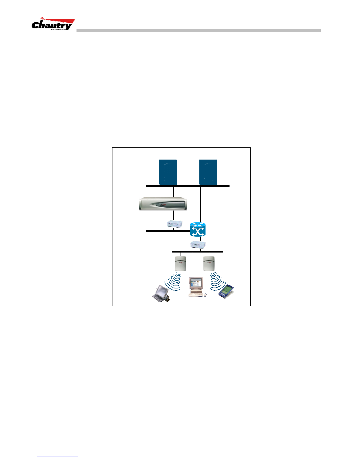
In addition to the BeaconMasters and BeaconPoints, the solution requires two other
components, which are standard for enterprise and service provider networks:
RADIUS Server
•
(Remote Access Dial-In User Service) (RFC2865 and RFC2866),
or other authentication server. Assigns and manages ID and Password protection
throughout the network. Used for authentication of the wireless users.
DHCP Server
•
(Dynamic Host Configuration Protocol) (RFC2131). Assigns IP
addresses, gateways and subnet masks dynamically. Also used by the
BeaconPoints to discover the location of the BeaconMaster during the initial
registration process.
RADIUS
Authentication Server
DHCP
Server
BeaconMaster
Ethernet Switch
Router
Ethernet Switch
BeaconPoint
Wir el ess
Devi ce
Wir el ess
Devi ce
Figure 2: Chantry BeaconWorks Solution
The BeaconMaster appears to the existing network as if it were an access point, but in
fact one BeaconMaster controls many BeaconPoints.
The BeaconMaster has built-in capabilities to recognize and manage the
BeaconPoints. The BeaconMaster activates the BeaconPoints, enables them to receive
wireless traffic from wireless devices, processes the data traffic from the
BeaconPoints and forwards or routes that data traffic out to the network. This
processing includes authenticating requests and applying access policies.
Simplifying the BeaconPoints make them:
• cost-effective
• easy to manage
• easy to deploy.
Chantry Networks Inc. Copyright 2004. All rights reserved. BeaconWorks Rel 2.0 (051304) Page 6 of 134
Page 7

BeaconWorks User Guide – The Chantry BeaconWorks Solution
Putting control on an intelligent centralized BeaconMaster enables:
• centralized configuration, management, reporting, maintenance
• high security
• flexibility to suit enterprise
• scalable and resilient deployments with a few BeaconMasters controlling hundreds
of BeaconPoints.
Here are some of the BeaconWorks system advantages:
Scales up to Enterprise
capacity
Integrates in existing
network
Offers centralized
management and
control
Provides easy
deployment of
BeaconPoints
Provides security via
user authentication
Provides security via
filters and privileges
One BeaconMaster controls as many as 200 BeaconPoints. In turn
each BeaconPoint can handle up to 254 wireless devices. With
additional BeaconMasters, the number of wireless devices the
Chantry system can support is in the thousands.
A BeaconMaster can be added to an existing enterprise network as
a new network device, greatly enhancing its capability without
interfering with its existing functionality. Integration of the
BeaconMasters and BeaconPoints does not require any
reconfiguration of the existing infrastructure (e.g. VLANs).
An administrator accesses the BeaconMaster in its centralized
location and uses its user interface to monitor and administer the
entire wireless network. The BeaconMaster has functionality to
recognize, configure and manage the BeaconPoints and distribute
new software releases.
The initial configuration of the BeaconPoints on the centralized
BeaconMaster can be done with an automatic “discovery”
technique.
BeaconWorks uses existing authentication (AAA) servers to
authenticate and authorize users.
BeaconWorks uses virtual networking techniques to create
separate virtual networks with defined authentication and billing
services, as well as access policies and privileges.
Supports seamless
mobility and roaming
Integrates third-party
access points
Prevents rogue devices
Provides accounting
services
Offers troubleshooting
capability
Chantry Networks Inc. Copyright 2004. All rights reserved. BeaconWorks Rel 2.0 (051304) Page 7 of 134
BeaconWorks supports seamless roaming of a wireless device
from one BeaconPoint to another on the same BeaconMaster or on
a different BeaconMaster.
BeaconWorks can integrate legacy third-party access points, using
a combination of network routing and authentication techniques.
Rogue devices will not be authenticated by the BeaconMaster,
preventing unproved devices from masquerading as valid
BeaconPoints.
The BeaconMaster has software to track and log wireless user
sessions, user group activity, and other activity reporting, enabling
the generation of consolidated billing records.
The BeaconMaster software logs system and session activity and
provides reports to aid in troubleshooting analysis.
Page 8
BeaconWorks User Guide – BeaconWorks and Your Enterprise Network
BeaconWorks and Your Enterprise Network
Network traffic flow in the BeaconWorks System
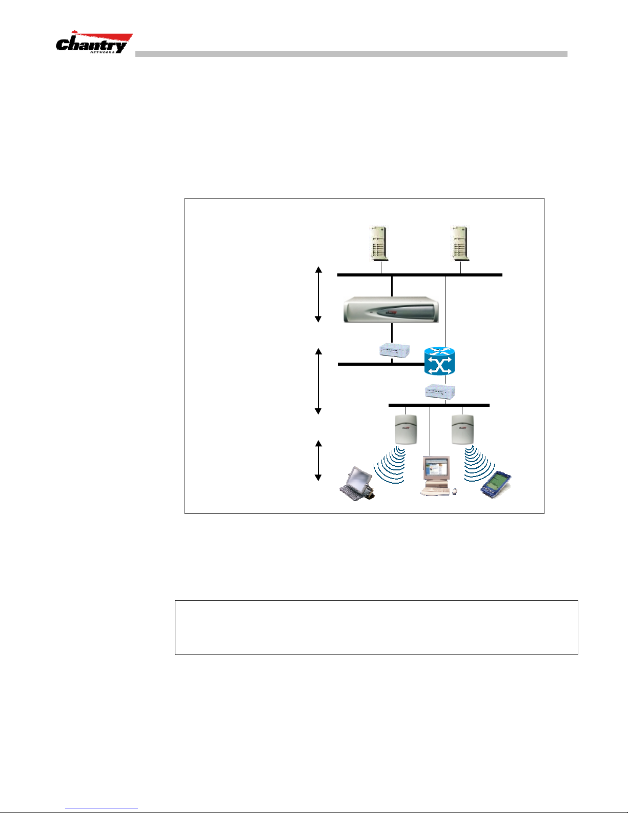
The diagram below shows a simple configuration with a single BeaconMaster and two
BeaconPoints, each supporting a wireless device. A RADIUS server on the network
provides authentication, and a DHCP server is used by the BeaconPoints to discover
the location of the BeaconMaster during the initial registration process. Also present
in the network are routers and ethernet switches.
BeaconMa ster
control & routing
Beac onMaster aut hent icates
Wir eless Use r, forwards IP
packe t to wired netw ork.
BeaconMa ster /
BeaconPoint
tunnelling
• BP sends data traffic to BM
through a UDP tunnel
called WASSP .
• BM controls BP through
WASSP tunnel.
• Using WASSP tunnels, BM
allow wireless clients to roam
to BPs on different BMs.
802.11
IP packet transmiss ion
802. 11 be acon & probe ,
wire le ss dev ice associates
with a BeaconPoint b y its SSID.
BeaconMaster
BeaconPoint
RADIUS
Auth entication Server
Ethernet
Switch
Wir eless
Device
DHCP
Server
Router
Ethernet
Switch
Wir eless
Device
Each wireless device sends IP packets in the 802.11 standard to the BeaconPoint. The
BeaconPoint uses a UDP (User Datagram Protocol) based tunnelling protocol called
CAPWAP Tunnelling Protocol (CTP) to encapsulate the packets and forward them to
the BeaconMaster.
Note:
The CTP protocol defines a mechanism for the control and provisioning of
wireless access points (CAPWAP) through centralized access controllers. In addition,
it provides a mechanism providing the option to tunnel the mobile client data between
the access point and the access controller.
The BeaconMaster decapsulates the packets, and routes these to destinations on the
network, after authentication by the RADIUS server.
The BeaconMaster functions like a standard router, except that it is configured to
route only between its ingress ports (incoming wireless device traffic via
BeaconPoints) and egress ports (traffic out to the wired network). The BeaconMaster
Chantry Networks Inc. Copyright 2004. All rights reserved. BeaconWorks Rel 2.0 (051304) Page 8 of 134
Figure 3: BeaconWorks Traffic Flow diagram
Page 9

can also be configured to simply forward traffic to a default or static route if dynamic
routing is not preferred.
Network security
The Chantry BeaconWorks system provides features and functionality to control
network access. These are based on standard wireless network security practices.
Current wireless network security methods provide a degree of protection. These
methods include:
• Shared Key authentication, that relies on Wired Equivalent Privacy (WEP) keys
• Open System, that relies on Service Set Identifiers (SSIDs)
• 802.1x that is compliant with Wi-Fi Protected Access (WPA)
• Captive Portal based on Secure Sockets Layer (SSL) protocol
The Chantry BeaconWorks system supports these encryption approaches:
• Wired Equivalent Privacy (WEP), a security protocol for wireless local area
BeaconWorks User Guide – BeaconWorks and Your Enterprise Network
networks defined in the 802.11b standard.
• Wi-Fi Protected Access (WPA) with Temporal Key Integrity Protocol (TKIP), also
• Advanced Encryption Standard (AES).
Authentication
The Chantry BeaconMaster relies on a RADIUS server, or authentication server, on
the enterprise network to provide the authentication information (whether the user is
to be allowed or denied access to the network).
The BeaconMaster provides authentication using:
• Captive Portal, a browser-based mechanism that forces users to a web page.
• RADIUS (using IEEE 802.1x)
The
standard. This mechanism is implemented at the port, blocking all data traffic between
the wireless device and the network until authentication is complete. Authentication
by 802.1x standard uses Extensible Authentication Protocol (EAP) for the message
exchange between the BeaconMaster and the RADIUS server.
When 802.1x is used for authentication, the BeaconMaster provides the capability to
dynamically assign per-wireless-device WEP keys (called per-station WEP keys in
802.11).
known as WPA version 1. (BeaconWorks Release 2.0)
802.1x mechanism
is a standard for authentication developed within the 802.11
Note:
In BeaconWorks Release 2.0, a RADIUS redundancy feature is provided,
where you can define a failover RADIUS server (up to 2 servers) in the event that the
active RADIUS server fails.
Privacy
Privacy is a mechanism that protects data over wireless and wired networks, usually
by encryption techniques.
Chantry Networks Inc. Copyright 2004. All rights reserved. BeaconWorks Rel 2.0 (051304) Page 9 of 134
Page 10

BeaconWorks User Guide – BeaconWorks and Your Enterprise Network
Chantry supports the Wired Equivalent Privacy (WEP) standard common to
conventional access points.
It also provides Wi-Fi Protected Access (WPA) encryption, based on Pairwise Master
Key (PMK) and Temporal Key Integrity Protocol (TKIP). This second option is
available when the AAA (802.1x) authentication technique is used.
Interaction with Wired Networks: Virtual Network Services
BeaconWorks provides a versatile means of mapping wireless networks to the
topology of an existing wired network. This is accomplished through the assignment
Virtual Network Services
of
When you set up Virtual Network Services (VNS) on the BeaconMaster, you are
defining subnets for groups of wireless users. This VNS definition creates a virtual IP
subnet where the BeaconMaster acts as a default gateway for wireless devices.
This technique enables policies and authentication to be applied to the groups of
wireless users on a VNS, as well as the collecting of accounting information on user
sessions that can be used for billing.
.
When a VNS is set up on the BeaconMaster:
• one or more BeaconPoints (by radio) are associated with it
• a range of IP addresses is set aside for the BeaconMaster’s DHCP server to assign
to wireless devices.
If routing protocol is enabled, the BeaconMaster advertises the VNS as a routable
network segment to the wired network, and routes traffic between the wireless devices
and the wired network.
Note:
In BeaconWorks Release 2.0, each radio on a BeaconPoint can participate in up
to four VNSs, via the multi-SSID function.
Static Routing and Routing Protocols
Routing can be used on the BeaconMaster to support the VNS definitions.
In the User Interface on the BeaconMaster, you can configure routing on the
BeaconMaster to use one of the following routing techniques:
• Static routes: Use static routes to set the default route of a BeaconMaster so that
legitimate wireless device traffic can be forwarded to the default gateway.
• Open Shortest Path First (OSPF) (RFC2328): Use OSPF to specify the next best
hop (route) of a BeaconMaster.
Open Shortest Path First (OSPF) is a protocol designed for medium and large IP
networks, with the ability to segment routers into different routing areas for routing
information summarization and propagation.
Policy: Packet Filtering
Policy
refers to the rules that allow different network access to different groups of
users. The BeaconWorks system can link authorized users to user groups. These user
groups then can be confined to predefined portions of the network.
Chantry Networks Inc. Copyright 2004. All rights reserved. BeaconWorks Rel 2.0 (051304) Page 10 of 134
Page 11

In the BeaconWorks system, policy is carried out by means of packet filtering, within
a VNS.
In the BeaconMaster user interface, you set up a filtering policy by defining a set of
hierarchical rules that allow (or deny) traffic to specific IP addresses, IP address
ranges, or services (ports). The sequence and hierarchy of these filtering rules must be
carefully designed, based on your enterprise’s user access plan.
The authentication technique selected determines how filtering is carried out:
• If authentication is by SSID and captive portal, a global filter will allow all users to
get as far as the Captive Portal web page, where login occurs. When authentication
is returned, then filters are applied, based on user ID and permissions.
• If authentication is by AAA (802.1x), there is no need for a global filter. Users will
already have logged in and have been authenticated before being assigned an IP
address. At this point, filters are applied, based on user ID and permissions.
Mobility and Roaming
The 802.11 standard allows a wireless device to preserve its IP connection when it
roams from one access point to another on the same subnet. However, if a user roams
to an access point on a different subnet, the user is disconnected.
BeaconWorks User Guide – BeaconWorks and Your Enterprise Network
Availability
Chantry BeaconWorks has functionality that supports mobility on any subnet in the
network. Wireless device users can roam between BeaconPoints on any subnet
without having to renew the IP connection
The BeaconMaster stores the wireless device’s current session information, such as IP
address and MAC address. If the wireless device has not disassociated, then when it
requests network access on a different BeaconPoint, the BeaconMaster can match its
session information and recognize it as still in a current session.
In addition, a BeaconMaster can learn about other BeaconMasters on the network, and
then exchange client session information. This enables a wireless device user to roam
seamlessly between different BeaconPoints on different BeaconMasters.
BeaconWorks provides seamless availability against BeaconPoint outages,
BeaconMaster outages, and even network outages.
For example, if one BeaconPoint fails, coverage for the wireless device is
automatically provided by the next nearest BeaconPoint.
If a BeaconMaster fails, all of its associated BeaconPoints, or access points, can
automatically migrate to another BeaconMaster that has been defined as the secondary
or backup BeaconMaster. When the original BeaconMaster returns to the network, the
BeaconPoints automatically re-establish their normal connection with their original
BeaconMaster.
Chantry Networks Inc. Copyright 2004. All rights reserved. BeaconWorks Rel 2.0 (051304) Page 11 of 134
Page 12

BeaconWorks User Guide – BeaconWorks Release 2.0 Features: Overview
BeaconWorks Release 2.0 Features: Overview
Backwards compatibility with Release 1.1 on the BeaconPoint
In Release 2.0, the upgrading of software on the BeaconPoint is no longer automatic.
You can schedule the upgrade and select the image to be used. Use the
Maintenance
One result of this feature is that you can continue to use BeaconPoints that still have
Release 1.1 software. However, there are certain limitations to the functions
supported. In Release 1.1, a BeaconPoint appeared as a single entity in a VNS, and
could be assigned to only one VNS. Both radios had the same properties. Privacy by
WPA was not supported. The default privacy mechanism was dynamic WEP.
A BeaconPoint that is still running a Release 1.1 software image will therefore retain
these parameters, and these parameters are not modifiable. The new capability will
only be available when the BeaconPoint is upgraded from Release 1.1 to Release 2.0
software.
Backwards compatibility with Release 1.1 on the BeaconMaster
Upgrading to BeaconWorks 2.0 requires a migration of the database on the
BeaconMaster. In order to preserve the BeaconMaster network configurations that you
defined in Release 1.1 software, the new release provides scripts that migrate the
configuration data into the new data format.
screen to select and schedule an upgrade.
BeaconPoint
Details of the software upgrade procedure, and the appropriate script to run are
available in Technical Release Notes.
Multi-SSID: BeaconPoint radios on more than one VNS
In Release 1.1, a BeaconPoint appeared as a single entity in a VNS, and could be
assigned to only one VNS.
In Release 2.0, each radio on a BeaconPoint BP200 can participate in up to four
VNSs, for a total of eight VNSs per BeaconPoint. This provides greater flexibility in
defining VNSs and providing support to a wide range of wireless devices.
This flexibility enables the network to support wireless devices with either:
• 802.11g radios on the 2.4 GHz band, and legacy support to 802.11b on the same
band
• 802.11a radios on the 5 GHz band.
Furthermore, a VNS can be set up to support only one type of radio, for specific types
of wireless traffic such as voice-over-internet traffic,
Use the
radios to a VNS. The
Virtual Network Configuration: Topology
Virtual Network Configuration: Privacy
one WEP key to be set up. After a VNS definition has been saved, you can view (in
BeaconPoint Configuration
the
screen) the properties for each radio for a selected
BeaconPoint, including a list of the VNSs to which the radio has been assigned.
screen to assign the BeaconPoint
screen will allow only
Chantry Networks Inc. Copyright 2004. All rights reserved. BeaconWorks Rel 2.0 (051304) Page 12 of 134
Page 13

BeaconWorks User Guide – BeaconWorks Release 2.0 Features: Overview
Privacy using Wi-Fi Protected Access (WPA)
The VNS Privacy configuration function now includes Wi-Fi Protected Access
(WPA) privacy, a new security solution that adds authentication and enhanced WEP
encryption with key management. . WPA specifies IEEE 802.1x authentication with
Extensible Authentication Protocol (EAP).
WPA uses the Temporal Key Integrity Protocol (TKIP) mechanism, which shares a
starting key between devices, and then changes their encryption key for every packet.
Configure the WPA option and define the initial shared key in the
Configuration: Privacy
BeaconPoint software: Dual image capability
screen
The BeaconPoint in Release 2.0 keeps a backup copy of its software image. When a
software upgrade is sent to the BeaconPoint, the upgrade becomes the BeaconPoint’s
current image and the previous image becomes the backup. In the event of failure of
the current image, the BeaconPoint will run the backup image.
BeaconPoint software: Dynamic reconfiguration (without reboot)
In Release 2.0, a number of the properties of each radio on a BeaconPoint can be
modified (in the
BeaconPoint Configuration
screen) without requiring a reboot of the
BeaconPoint. However, modifying the following properties does require a reboot:
• enabling or disabling either radio
• changing the radio channel.
In addition, the BeaconPoint must be rebooted after it has been added to a VNS, or the
radio assignment in a VNS has been changed. Any changes to security also require a
reboot of the BeaconPoint.
BeaconPoint Statistics
Radio statistics are available from a BeaconPoint running Release 2.0 software. On
the BeaconMaster user interface, two displays (in the
Reports and Displays
user interface) show information about activity on a selected BeaconPoint:
Virtual Network
area of the
• Wired Ethernet Statistics by BeaconPoints
• Wireless Statistics by BeaconPoints, plus a subscreen that displays transmission
and association information by wireless client.
These displays are snapshots of the BeaconPoint activity at the current point in time.
The statistics displayed are those defined in the 802.11 MIB, defined in the IEEE
802.11 standard (in Section 11.4 and Annex D).
The BeaconMaster can also be configured to send these radio statistics as SNMP
messages to the SNMP monitoring machine on a network.
Event reporting using Syslog
In addition to viewing BeaconWorks event messages in the BeaconWorks Reports and
Displays area of the user interface, you can also set up the BeaconMaster to relay
event messages on to a centralized Event Server on your enterprise network. The relay
is done using the syslog protocol.
Use the
to define the location of one or more centralized Event Servers.
Chantry Networks Inc. Copyright 2004. All rights reserved. BeaconWorks Rel 2.0 (051304) Page 13 of 134
BeaconMaster System Maintenance
screen to enable the syslog function and
Page 14

BeaconWorks User Guide – BeaconWorks Release 2.0 Features: Overview
Capacity for Redundant RADIUS servers
BeaconWorks Release 2.0 provides the capability to define more than one RADIUS
server for authentication, and to provide the priority of use during a failover situation.
Use the
Virtual Network Configuration: Authentication
screen to define the RADIUS
server location and priority.
Detection of Rogue APs
BeaconWorks Release 2.0 provides a new mechanism that recognizes rogue access
points. The mechanism scans radio frequency (RF) activity on the BeaconPoints and
builds a data log of this activity. This data is then analyzed through various algorithms
that assist in distinguishing rogue access points from legitimate activity.
Use the
BeaconKeeper
function in the user interface to enable this mechanism. Once
enabled, you can configure and schedule the RF scan mechanism, maintain a list of
“friendly AP” access points, and view the detected access points for which a match is
not found in the “friendly AP” list.
Quality of Service (QoS) on a VNS: Spectralink Voice Protocol (SVP)
A VNS can be configured to handle voice-over internet traffic using SpectraLink
Voice Protocol (SVP), a protocol developed by SpectraLink for implementation on an
access point. The SVP protocol facilitates voice prioritization over an 802.11 wireless
LAN that will carry voice packets from SpectraLink wireless telephones.
Use the
Virtual Network Configuration: Topology
screen to set up a VNS for voiceover-internet traffic with SVP prioritization. A number of conditions apply to a VNS
for voice-over-internet.
BeaconPoint static configuration: Branch Office, Phase 1
The BeaconPoint static configuration feature provides BeaconWorks capability for a
network with the central office / branch office model.
In the branch office scenario, BeaconPoints are installed in a remote site. The
BeaconPoints require the capability to interact both in the local site network and in the
central headquarters network. To achieve this, the BeaconPoint’s automatic process of
discovery and registration with the BeaconMaster is disabled, and a static
configuration is used instead.
Chantry Networks Inc. Copyright 2004. All rights reserved. BeaconWorks Rel 2.0 (051304) Page 14 of 134
Page 15

BeaconMaster: Startup
BeaconMaster Features and Installation
The Chantry BeaconMaster is a network device designed to be integrated into an
existing wired Local Area Network (LAN).
The BeaconMaster provides centralized management, network access and routing to
wireless devices that are using BeaconPoints to access the network. It can also be
configured to handle data traffic from third-party access points.
The BeaconMaster performs the following functions:
BeaconWorks User Guide – BeaconMaster: Startup
Figure 4: The Chantry BeaconMaster
• Controls and configures BeaconPoints, providing centralized management
• Authenticates wireless devices that contact a BeaconPoint
• Assigns each wireless device to a VNS when it connects
• Routes traffic from wireless devices, using VNSs, to the wired network
• Applies filtering policies to the wireless device session
• Provides session logging and accounting capability.
The BeaconMaster is rack-mountable and comes in two models:
BeaconMaster 100 (BM100)
•
:
• Four Fast-Ethernet ports, (10/100 BaseT), supporting up to 60 BeaconPoints
• One management port, (10/100 BaseT)
• One console port (DB9 serial)
• Power supply, either standard (S), or redundant (R)
BeaconMaster 1000 (BM1000)
•
:
• Two GigE ports (dual 1GB SX network interfaces), supporting up to 200
BeaconPoints
• One management port, (10/100 BaseT)
• One console port (DB9 serial)
• Power supply, either standard (S), or redundant (R)
Installing the BeaconMaster
Before you begin installation, make sure that a site survey has been done, to determine
the number and location of BeaconPoints and BeaconMasters required. The site
survey should take a number of factors into consideration, including:
Chantry Networks Inc. Copyright 2004. All rights reserved. BeaconWorks Rel 2.0 (051304) Page 15 of 134
Page 16

BeaconWorks User Guide – BeaconMaster: Startup
• coverage areas
• number of users
• architectural features that affect transmission
• existing wired network and access to ethernet cabling
• type of mount (wall, ceiling, plenum) for BeaconPoints
• type of power (Power-over-Ethernet or AC adaptor) for BeaconPoints
• physical security of the BeaconMaster, including access control.
Installing the BeaconMaster
1. Unpack the BeaconMaster from its shipment carton. Follow the instructions in the
Installation Guide
included with the unit to:
• Check that all parts are present, including the ethernet cross-over cable
• Install the BeaconMaster, using its rack mounts, or stand-alone table mount
• Plug in the BeaconMaster power supply (single or dual).
Data ports (4-port version)
←
Management ports
←
↑
Power supply Power On/Off switch
(single or dual)
↑
2. Perform the First-Time Setup of the BeaconMaster, to change its factory default
IP address (see next topic)
3. After that, connect the BeaconMaster to the enterprise LAN.
Steward
28A5776-0A2
Power Cord,
BeaconMaster
First-Time Setup of BeaconMaster
Management Port First-Time Set Up
Before you can connect the BeaconMaster to the enterprise network, you must change
the IP address of the BeaconMaster management port from its factory default to the IP
address suitable for your enterprise network.
Figure 5: The Chantry BeaconMaster – back view diagram
Note
: Install ferrite beads as shown
in the two diagrams:
on the BeaconMaster power
←
supply cord, and on the
BeaconMaster ethernet cable
→
Steward
28A2024-0A0
RJ45 Data Cord,
BeaconMaster
To access the BeaconMaster for this initial setup, use a laptop computer, running
Internet Explorer 6.0 (or higher) web browser, attached to the BeaconMaster’s
ethernet Management Port (RJ45 port) via an ethernet cross-over cable (cable
provided with the BeaconMaster).
Chantry Networks Inc. Copyright 2004. All rights reserved. BeaconWorks Rel 2.0 (051304) Page 16 of 134
Page 17
BeaconWorks User Guide – BeaconMaster: Startup
The factory default management port setup of the BeaconMaster is:
Host Name: BM0001
Management Port IP address: 192.168.10.1:5825
Management Network Mask: 255.255.255.0
Changing the Management Port IP address web browser, ethernet port method
1. Connect a cross-over ethernet cable between the ethernet port of the laptop and
ethernet Management Port of the BeaconMaster.
2. Statically assign an unused IP address in the 192.168.10.0/24 subnet for the
ethernet port of the PC (for example, 192.168.10.205).
3. Run Internet Explorer (version 6.0 or above) on the laptop.
4. Point the browser to the URL https://192.168.10.1:5825. This URL launches the
web-based GUI on the BeaconMaster.
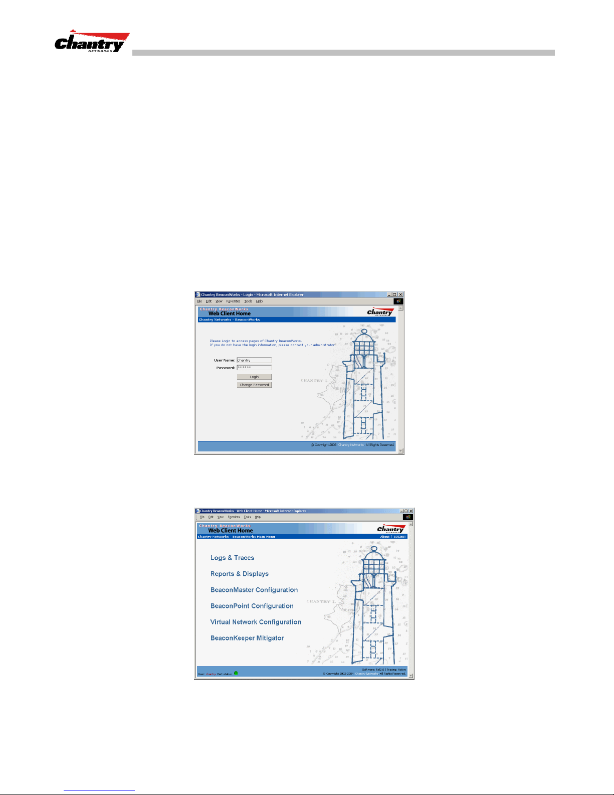
The Chantry BeaconWorks system login screen appears.
Screen 1: Chantry BeaconWorks User Interface Login
5. Key in the factory default
Login
Click on the
button. The main menu screen appears.
Screen 2: Chantry BeaconWorks User Interface Main Menu
User Name
(“chantry”) and
Password
(“abc123”) .
6. Click on the BeaconMaster Configuration menu option to navigate to the
BeaconMaster Configuration
screen.
Chantry Networks Inc. Copyright 2004. All rights reserved. BeaconWorks Rel 2.0 (051304) Page 17 of 134
Page 18
BeaconWorks User Guide – BeaconMaster: Startup
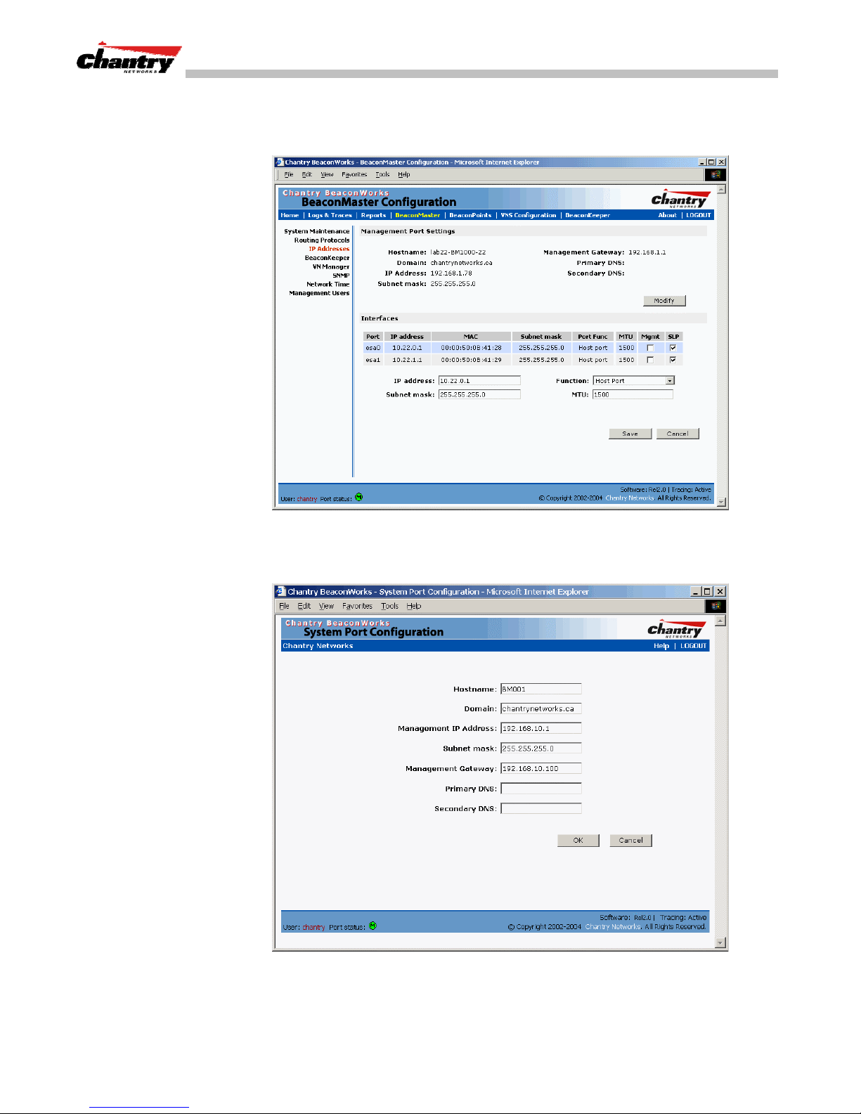
7. In the left-hand list, click on the
IP Addresses
option. The Management Port
Settings area (top portion of the screen) displays the factory settings for the
BeaconMaster.
Screen 3: BeaconMaster Configuration – IP Addresses – Management Port
8. To modify Management Port Settings, click the
Configuration
screen appears.
Modify
button. The
System Port
Chantry Networks Inc. Copyright 2004. All rights reserved. BeaconWorks Rel 2.0 (051304) Page 18 of 134
Screen 4: Modify Management Port Settings (System Port Configuration)
Page 19

9. Key in:
BeaconWorks User Guide – BeaconMaster: Startup
Hostname
Domain
Management
IP Address
Subnet mask
The name of the BeaconMaster.
The IP domain name of the enterprise network
The new IP address for the BeaconMaster’s management
port (change this as appropriate to the enterprise network).
For the IP address, the appropriate subnet mask to separate
the network portion from the host portion of the address
(typically 255.255.255.0)
Management Gateway
Primary DNS
Secondary DNS
OK
10. Click
11. Click on the
to return to the
Save
button, to save the port changes.
The default gateway of the network.
The primary name server used by the network.
The secondary name server used by the network.
BeaconMaster Configuration
screen.
The web connection between the laptop and the BeaconMaster is now lost, because
their IP addresses are now on different networks.
Add the BeaconMaster to your enterprise network
1. Disconnect the laptop from the BeaconMaster Management Port.
2. Connect the BeaconMaster Management Port to the enterprise ethernet LAN.
Now you will be able to launch the BeaconWorks GUI again, with the system visible
to the enterprise network.
The remaining steps in initial configuration of the BeaconWorks system are described
in the next topic, after an overview of the GUI.
Chantry Networks Inc. Copyright 2004. All rights reserved. BeaconWorks Rel 2.0 (051304) Page 19 of 134
Page 20
BeaconWorks User Guide – BeaconMaster: Startup
The Graphical User Interface (GUI): Overview
Note:
The Chantry Graphical User Interface is web-based. The only browser it
supports is Microsoft Internet Explorer 6.0 or above.
The administrator can configure and administer the BeaconWorks system using the
web-based Graphical User Interface.
To run the Graphical User interface
1. Launch Microsoft Internet Explorer (version 6.0 or above).
2. In the address bar, key in the URL https://x.x.x.x:5825
(your management gateway as defined in initial setup plus port 5825, formerly
factory default 192.168.10.1:5825)
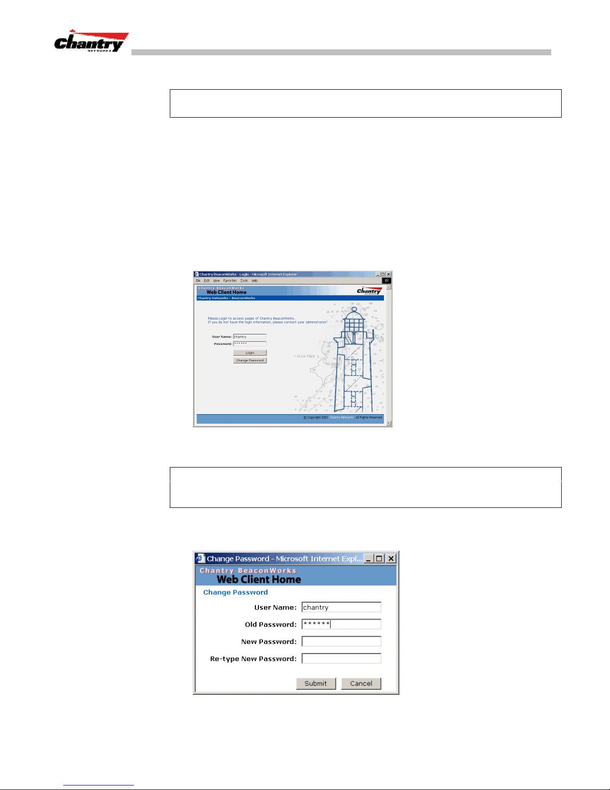
The Chantry BeaconWorks system login screen appears.
Screen 5: Chantry BeaconWorks User Interface Login
3. Key in the factory default
Note:
In the
BeaconMaster Configuration: Management Users
User Name
(“chantry”) and
Password
(“abc123”).
screen, you can define
which user names have full read/write access to the user interface (“Admin” users)
and which users have “read-only” privileges. This is described in a later topic.
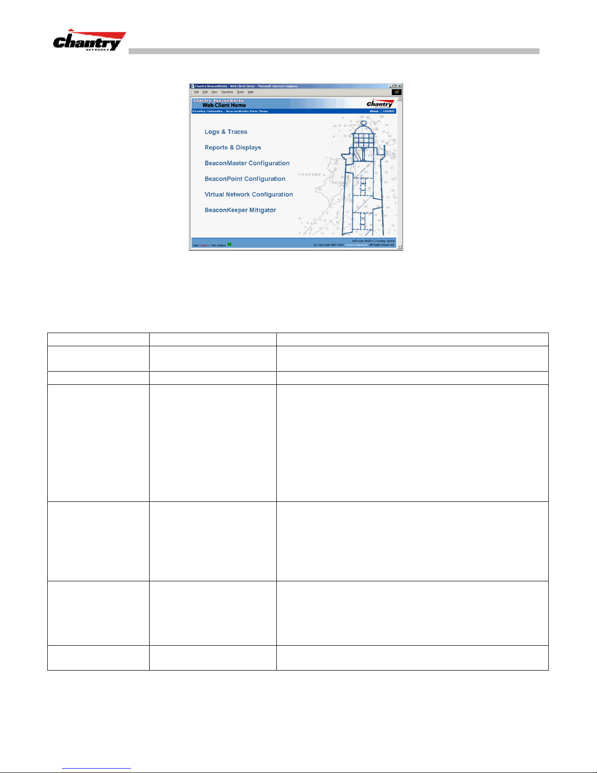
4. To change the password, click on the
Password
button. The
Change Password
popup screen appears.
Screen 6: Change Password popup
5. Enter the new password and click on the
Submit
button.
Chantry Networks Inc. Copyright 2004. All rights reserved. BeaconWorks Rel 2.0 (051304) Page 20 of 134
Page 21
BeaconWorks User Guide – BeaconMaster: Startup
6. In the Login screen, click on the
The five areas in the BeaconWorks user interface are accessed from the main menu
(above) or, in each area, by clicking on the tab across the top of each screen. Within
each area, you access the associated subscreens by clicking on an item in the left-hand
list in each screen. A few subscreens are popups from buttons on the parent screen.
Tab Screen Function
Logs & Traces
Reports & Displays
BeaconMaster
Configuration
BeaconPoint
Configuration
Virtual Network
Configuration
BeaconKeeper
Mitigator
System Maintenance
Routing Protocols
IP Addresses
BeaconKeeper
VN Manager
SNMP
Network Time
Management Users
Highlight a BP
Access Approval
BP Maintenance
BP Registration
BP Failover
Client Disassociate
Add a subnet
VNS Topology
VNS Authentication
VNS Filtering
VNS Privacy
Logs normal events and alarm events.
Trace logs are by component.
Access to various on-screen reports
Various: shutdown, enable syslog.
Define static routes, configure OSPF.
Set up management port (Modify screen)
Set up the data ports.
Enable “detect rogue APs” mechanism.
Manage multiple BeaconMasters.
Enable SNMP messages to be sent.
Configure synchronized time.
Define user level.
Modify properties, radios, static config.
Modify the status of a BeaconPoint.
View and set up BP software upgrade.
Define registration mode, pairing of BPs.
View failover VNS, part of VN Manager.
Force a wireless device to disassociate
Left-hand list. Enter name. Click to add.
Define the VNS
Define Filter IDs
Define filtering rules to control access
Set up WEP keys or WPA privacy.
Configure and view reports for the BeaconKeeper Mitigator
(rogue access point detection)
Login
button. The main menu screen appears.
Screen 7: Chantry BeaconWorks Main Menu
Chantry Networks Inc. Copyright 2004. All rights reserved. BeaconWorks Rel 2.0 (051304) Page 21 of 134
Page 22

BeaconWorks User Guide – BeaconWorks Configuration Steps: Overview
BeaconWorks Configuration Steps: Overview
To set up and configure the BeaconMaster and BeaconPoints, follow these steps:
First-Time Setup
1.
physical network by configuring the Management Port (as described earlier):
• modify the Management Port IP address to suit the enterprise network.
Data Port Setup
2.
the physical data ports. Determine whether the data ports will be:
• “host port”
• “router port”
• “3rd party AP port”
Routing Setup
3.
• static routes
• OSPF parameters, if appropriate to the network
BeaconPoint Initial Setup
4.
: Perform “First-Time Setup” of the BeaconMaster on the
: Set up the BeaconMaster on the physical network by configuring
: For any port defined as a “router port”, configure:
: Connect the BeaconPoints to the BeaconMaster:
• first determine their Registration mode (in the BeaconPoint Registration
screen)
• then power on the BeaconPoints (they will perform an automatic discovery
and registration process described in this User Guide)
BeaconPoint Configuration
5.
: Modify properties or settings of the BeaconPoint, if
desired.
Virtual Network Services (VNS) Setup
6.
: Set up one or more virtual subnetworks, on
the BeaconMaster. For each VNS:
• select radios on the BeaconPoints that the VNS will use.
• select and configure the authentication method for the wireless device user.
• select and configure the privacy method on the VNS.
Filtering Rules Setup
7.
: For each VNS, define the filtering rules that will control
network access:
• define global and default filtering rules, depending on network assignment
and authentication method
• define specific filtering rules for the Filter IDs (defined user groups in your
enterprise) that you want on this VNS.
Each of these steps is described in detail in the relevant section of this User Guide.
Chantry Networks Inc. Copyright 2004. All rights reserved. BeaconWorks Rel 2.0 (051304) Page 22 of 134
Page 23
BeaconWorks User Guide – BeaconWorks Configuration: Data Port and Routing Setup
BeaconWorks Configuration: Data Port and Routing Setup
Once the “First-Time Setup” described above is complete, the next step in the initial
setup of the BeaconMaster is to configure the data ports. Next, you can define routing
on a data port, if appropriate.
Setting Up the Data Ports
Configuring the data ports on the BeaconMaster
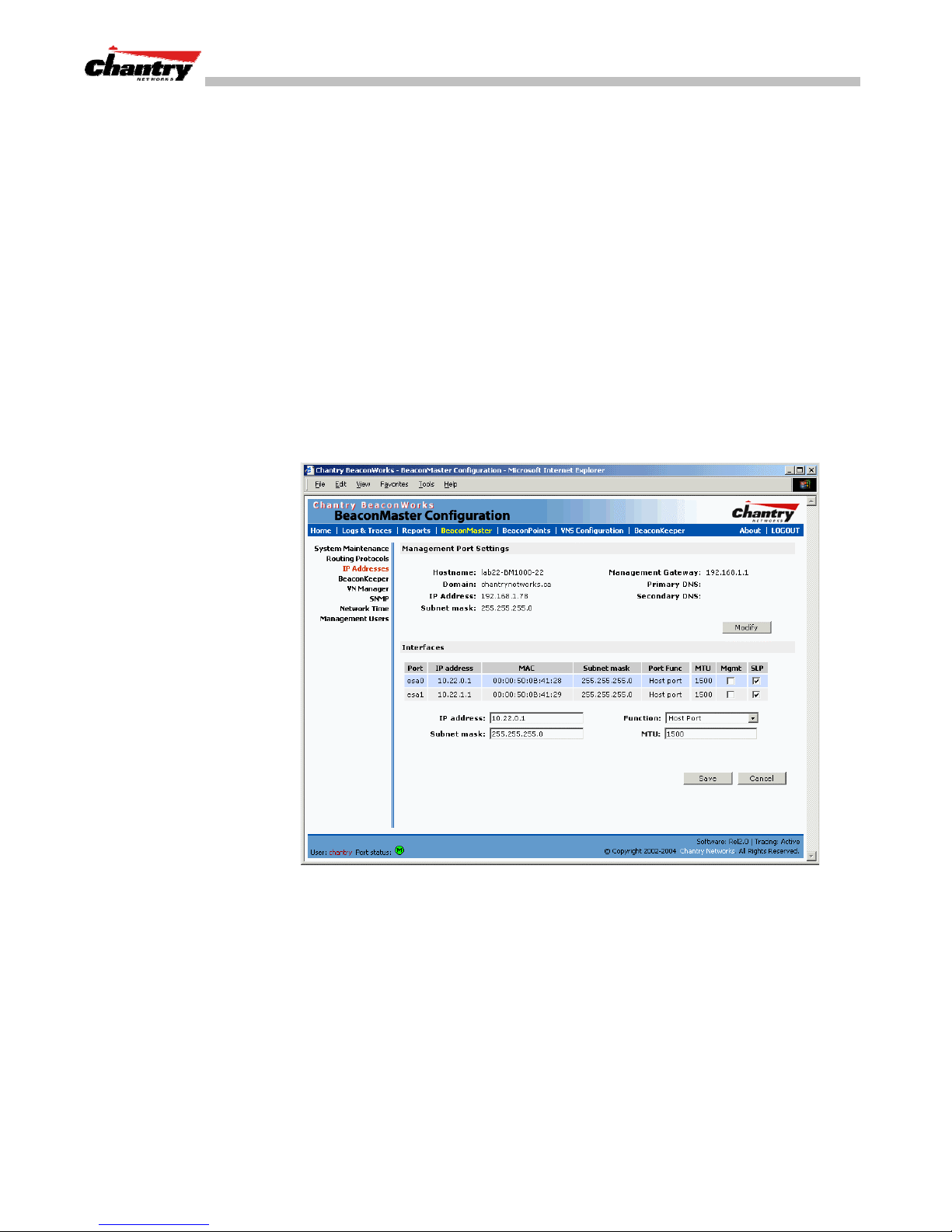
1. Click on the
BeaconMaster
tab in any screen. The
BeaconMaster Configuration
screen appears.
2. In the left-hand portion of the screen, click on the
Management Port Settings and Interfaces
The lower portion of the
Interfaces
, either the four ethernet ports (for the BM100), or the two ports (for
BeaconMaster Configuration
screen appears.
IP Address
screen displays the
option. The
the BM1000). For each port, the MAC address is displayed automatically.
3. Click in a port row to highlight it.
4. For the highlighted port, key in the:
IP address
Subnet mask
MTU
Chantry Networks Inc. Copyright 2004. All rights reserved. BeaconWorks Rel 2.0 (051304) Page 23 of 134
Screen 8: BeaconMaster Configuration – IP Addresses / Interfaces
IP Address of the physical ethernet port.
For the IP address, the appropriate subnet mask to separate the
network portion from the host portion of the address (typically
255.255.255.0)
Maximum Transmission Unit (maximum packet size for this
port). Default setting is
1500. Do not change this setting.
Page 24

BeaconWorks User Guide – BeaconWorks Configuration: Data Port and Routing Setup
Note:
In a “Branch Office” scenario, where the BeaconPoint is configured statically to
function on a local network whose MTU is lower than 1500, a mechanism on the
BeaconMaster automatically adjusts the MTU size to prevent packet fragmentation.
5. For the highlighted port, select its
3rd Party AP, Router (
Note
: It is recommended that one port be configured as a “Router” Port, so that static
routes and/or OSPF routing can be defined for the BeaconMaster. See next topic.
6. For the highlighted port, click the
Traffic
7. For the highlighted port, click the
port for BeaconPoint discovery and registration.
Note:
For the implications of these two options, see Port-Level Filtering (after the
next topic).
8. To save the port configuration, click
To cancel the entries without saving, click
Port Type or Function
A new BeaconMaster is shipped from the factory with all its data ports set up as “Host
ports”, and support of management traffic disabled on all data ports.
In the user interface, you can redefine the data ports to function as one of three types:
Host Port
•
on this port.
Function
from the drop-down list: Host Port,
see “Port Type” explanation below
Mgmt
checkbox on to allow
SLP
checkbox on to allow SLP protocol on this
Save
.
Cancel
.
)
Management
Define as “Host Port” any port to which
only
BeaconPoints are connected, in a
typical installation. When BeaconPoints are attached to a host port and assigned to
a VNS (see later in this guide), a virtual VNS port is created and wireless device
traffic is directed to the virtual VNS port, allowing the BeaconMaster to forward
traffic. IP forwarding and routing are disabled for third-party hosts attached to a
“Host Port”.
Third-Party Access Point Port
•
Define as “3rd-Party AP” any port to which you will connect
only
third-party
access points, in order for the BeaconMaster to manage these access points. The
BeaconMaster uses a combination of network routing and authentication
techniques to forward traffic on this port. BeaconPoints must not be attached to a
“3rd-Party AP” port.
Router Port
•
Define as “Router Port” a port that you wish to connect to an upstream next-hop
router in the network. Dynamic routing protocol such as OSPF can be turned on
for this port type.
BeaconPoints can be attached to a “Router” port. The BeaconMaster will create a
virtual VNS port and handle wireless device traffic in the same manner as a “Host
port”. Third-party access points must not be directly connected to a “Router” port
(unless the BeaconMaster is not required to manage these access points).
There is a fourth port type that is not configurable in the user interface:
Chantry Networks Inc. Copyright 2004. All rights reserved. BeaconWorks Rel 2.0 (051304) Page 24 of 134
Page 25

BeaconWorks User Guide – BeaconWorks Configuration: Data Port and Routing Setup
Virtual Network Services (VNS) Interface
•
A VNS port is a virtual port created automatically on the BeaconMaster when a
new VNS is defined (see later in this guide.) The VNS port becomes the default
gateway for wireless devices on this VNS. No BeaconPoints can be associated
with a VNS port and no routing is permitted on this port.
Note:
Management Port
The
is always a Host port, with management traffic support
enabled.
The chart below summarizes the port types and their functions:
Port Type IP Forwarding BeaconPoint
support
Host
Third-Party AP
Router
VNS
Port-Level Filtering of Unauthorized Traffic
No Yes Selectable No
No No Selectable No
Selectable
Route wireless device
traffic only
No No Selectable No
Yes Selectable Selectable
Port-based filters on the BeaconMaster are built in to protect it from unauthorized
access to system management functions and services via the ports.
When you select a port type, you automatically activate a set of filtering rules that
allow or deny traffic seeking access to specific services. For example:
• Router and Host interfaces allow access to specific management applications
(SSH, HTTPS, SNMP) and to BeaconPoint registration mechanisms.
Management traffic support
(SNMP, HTTP, TELNET,
SLP, RADIUS, DHCP)
Routing protocol
support (IP,
OSPF and PIM)
• Third Party AP and VNS interfaces deny access to management and BP
registration mechanisms, but allow access to captive portal (HTTP, HTTPS) and IP
assignment infrastructure (DHCP).
Only traffic allowed by the interface’s filter are allowed to reach the BeaconMaster
itself. All other traffic is dropped.
The physical Management Port that you configured in “First-Time Set-up” has a
restricted set of
Management Traffic
filtering rules that apply automatically. These
rules allow incoming traffic for SSH, HTTPS, FTP, SNMP, and outgoing traffic for
Syslog, NTP, and RADIUS, both directions for ICMP, and then deny all other traffic.
When you enable Management Traffic on one of the data ports (clicking the checkbox
on), you will activate the Management Traffic filter on that port. There is a second
way to enable Management Traffic, and invoke this implicit filter – in the VNS
Configuration: Topology, you can allow Management Traffic on a VNS by clicking a
checkbox on. (See later in this Guide.)
Note:
These implicit or built-in filtering rules work in conjunction with the VNS
filtering rules that you can define in a VNS Configuration (described later in this
Guide). The implicit rules on a port always override the administrator-defined rules,
unless specific access is defined and allowed, as in a filter for Captive Portal.
Chantry Networks Inc. Copyright 2004. All rights reserved. BeaconWorks Rel 2.0 (051304) Page 25 of 134
Page 26
BeaconWorks User Guide – BeaconWorks Configuration: Data Port and Routing Setup
Setting up Static Routes
It is recommended that one of the data ports be configured as a “Router” port. Then
you can define a default route to your enterprise network, either with a static route or
by using OSPF protocol. This will enable the BeaconMaster to forward wireless
packets to the remainder of the network.
Setting up a Static Route on the BeaconMaster
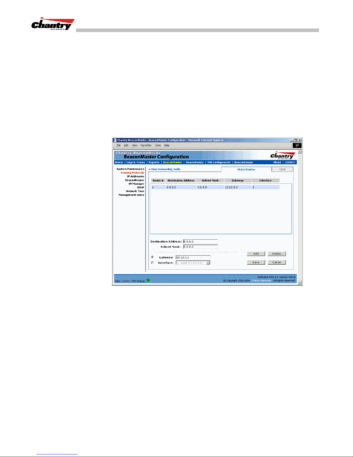
1. Click on the
BeaconMaster
tab in any screen. The
screen appears.
2. In the left-hand portion of the screen, click on the
Then click the
Static Routes
tab. The
Static Routes
BeaconMaster Configuration
Routing Protocols
option.
screen appears.
3. To add a new route, click in the
destination IP address of a packet.
[The destination network IP address that this static route applies to. Packets with
this destination address will be sent to the Destination below.]
To define a
key in 0.0.0.0
4. Key in the
separate the network portion from the host portion of the address (typically
255.255.255.0)
For the
5. Select an outbound destination for the packets, either:
Click on the radio button in the
gateway (the IP address of the specific router port or gateway, on the same subnet
as the BeaconMaster, to which to route these packets; that is, the IP address of the
next hop between the BeaconMaster and the packet’s ultimate destination) ,
Chantry Networks Inc. Copyright 2004. All rights reserved. BeaconWorks Rel 2.0 (051304) Page 26 of 134
Screen 9: BeaconMaster Configuration – Static Routes
default static route
Subnet Mask
. For the IP address, the appropriate subnet mask to
default static route
Destination Address
field, and key in the
for any unknown address not in the routing table,
for any unknown address, key in 0.0.0.0.
Gateway
field, and key in the IP address of the
Page 27
BeaconWorks User Guide – BeaconWorks Configuration: Data Port and Routing Setup
or
Click on the
6. Click on the
7. Click on
Viewing the Routing Table on the BeaconMaster
Interface
Add
Save
to update the routing table on the BeaconMaster.
button, and select a port from the drop-down list.
button. The new route appears in the list, numbered sequentially.
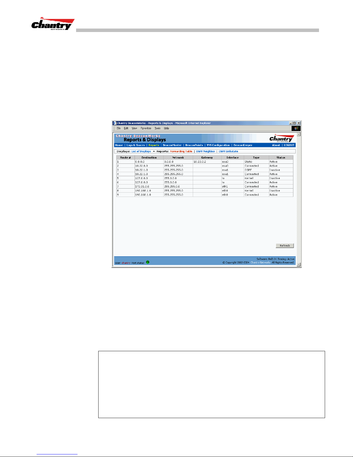
To view the static routes that have been defined for the BeaconMaster, click on
View Forwarding Table
the
Reports & Displays
the
tab. This displays the
area of the user interface.
Forwarding Table Screen
from
Screen 10: Report – Forwarding Table
This report displays all defined routes, whether static or OSPF, and their current
status. To update the display, click on the
Refresh
button.
Setting up OSPF Routing
For each data port defined as a “Router Port”, you can enable OSPF (as well as, or
instead of, defining static routes). First, you enable OSPF on the BeaconMaster, and
define the global OSPF parameters. Then you enable (or disable) OSPF on each port
that you defined as a “Router Port” in the data port setup.
Note:
Ensure that the OSPF parameters defined here for the BeaconMaster are
consistent with the adjacent routers in the OSPF area. For example:
• If the peer router has different timer settings, the protocol timer settings in the
BeaconMaster must be changed to match, in order to achieve OSPF adjacency.
• The MTU of the ports on either end of an OSPF link must match. The MTU for
ports on the BeaconMaster is defined as 1500, in the Interfaces area of the IP
Addresses screen, during data port setup. This matches the default MTU in
standard routers.
Chantry Networks Inc. Copyright 2004. All rights reserved. BeaconWorks Rel 2.0 (051304) Page 27 of 134
Page 28
BeaconWorks User Guide – BeaconWorks Configuration: Data Port and Routing Setup
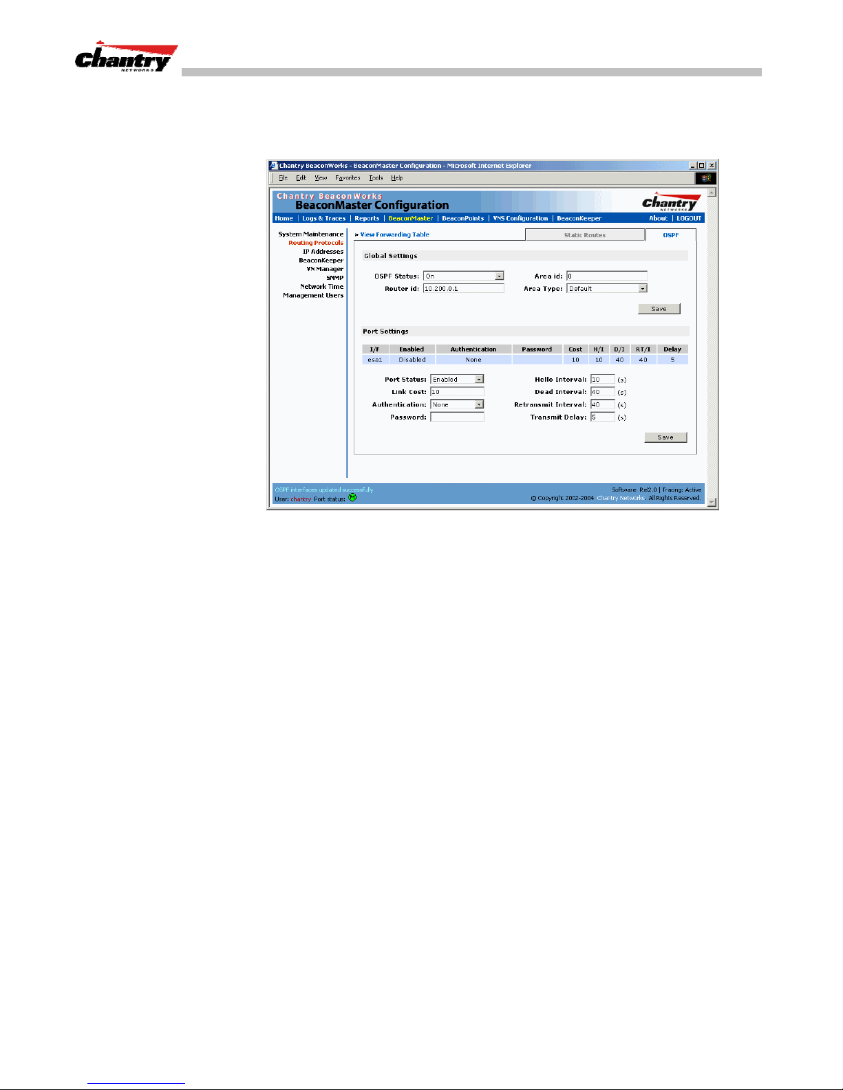
Setting up OSPF Routing on the BeaconMaster
1. Click on the
appears.
OSPF
tab in
Screen 11: BeaconMaster Configuration – Routing, OSPF tab
Routing Protocols
screen. The
OSPF Settings
screen
2. In the
Global Settings
area, enable OSPF on the BeaconMaster by filling in the
following fields:
OSPF Status:
Router ID:
To enable OSPF, select ON from the drop-down list.
If left blank, the OSPF daemon will automatically pick a
router ID from one of the BeaconMaster’s interface IP
addresses.
If filled in here with the IP address of the BeaconMaster, this
ID must be unique across the OSPF area.
Area ID:
0 is the main area in OSPF
Note:
(
The Area ID must be the same for all ports on the
BeaconMaster defined as router ports, to avoid creating an
area boundary in the BeaconMaster.)
Area Type:
Select Default (Normal), Stub or Not-so-stubby (OSPF area
types) from the drop-down list.
Save
3. To save these settings, click on the
4. In the
Port Settings
area, for each data port defined as a “Router Port”, you can
button.
enable (or disable) OSPF by filling in the following fields:
Port Status:
To enable OSPF on the port, select
down list.
Link Cost:
Key in the OSPF standard for your network for this port.
Default displayed is 10. (The cost of sending a data packet
on the interface. The lower the cost, the more likely the
interface is to be used to forward data traffic.)
Enabled
from the drop-
Chantry Networks Inc. Copyright 2004. All rights reserved. BeaconWorks Rel 2.0 (051304) Page 28 of 134
Page 29
BeaconWorks User Guide – BeaconWorks Configuration: Data Port and Routing Setup
Note:
If more than one port on the BeaconMaster is enabled for OSPF, it is desirable
to prevent the BeaconMaster from serving as a router for other network traffic (other
than the traffic from wireless device users controlled by the BeaconMaster). One
solution is to set the
Link Cost
to its maximum value of 65535. This will ensure that
the BeaconMaster is never the preferred OSPF route. Filters should also be defined in
Virtual Network Configuration – Filtering
the
screen that will drop routed packets.
Authentication:
Password:
From the drop-down list, select the authentication type set up
for the OSPF on your network:
None
Password
or
.
If “Password” was selected above, key it in here. This
password must match on either end of the OSPF connection.
Dead-Interval:
Hello-Interval:
Retransmit-Interval:
Transmit delay:
5. To save these settings, click on the
Time in seconds (displays OSPF default).
Time in seconds (displays OSPF default).
Time in seconds (displays OSPF default).
Time in seconds (displays OSPF default).
Save
button.
To confirm that the ports are set up for OSPF, and that advertised routes from the
upstream router are recognized, view the
Forwarding Table
report (described above
for static routes) by clicking the tab. This display shows the current routing table,
displaying the default, connected, static and OSPF routes.
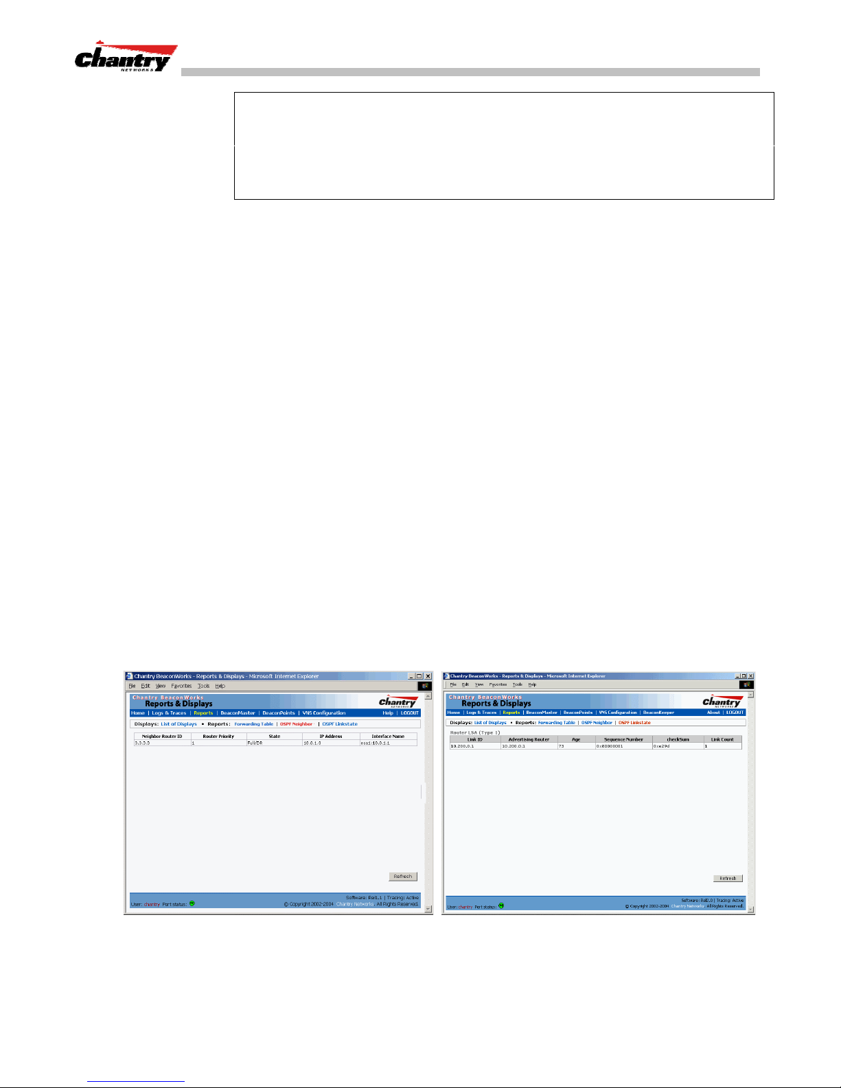
Two additional reports in the Reports and Displays area of the GUI display OSPF
information when the protocol is in operation:
OSPF Neighbor
•
report displays the current neighbors for OSPF (routers that have
interfaces to a common network)
OSPF Linkstate
•
report shows the Link State Advertisements (LSAs) received by
the currently running OSPF process. The LSAs describe the local state of a router
or network, including the state of the router’s interfaces and adjacencies.
Chantry Networks Inc. Copyright 2004. All rights reserved. BeaconWorks Rel 2.0 (051304) Page 29 of 134
Screen 12: Reports – OSPF Neighbor and Linkstate
Page 30
BeaconPoint: Startup
You are now ready to add the BeaconPoints to the BeaconWorks system and register
them with the BeaconMaster. Before the BeaconPoints can handle wireless traffic,
you will also need to assign the BeaconPoints to a VNS (see later in this Guide).
BeaconPoint (BP200) Features
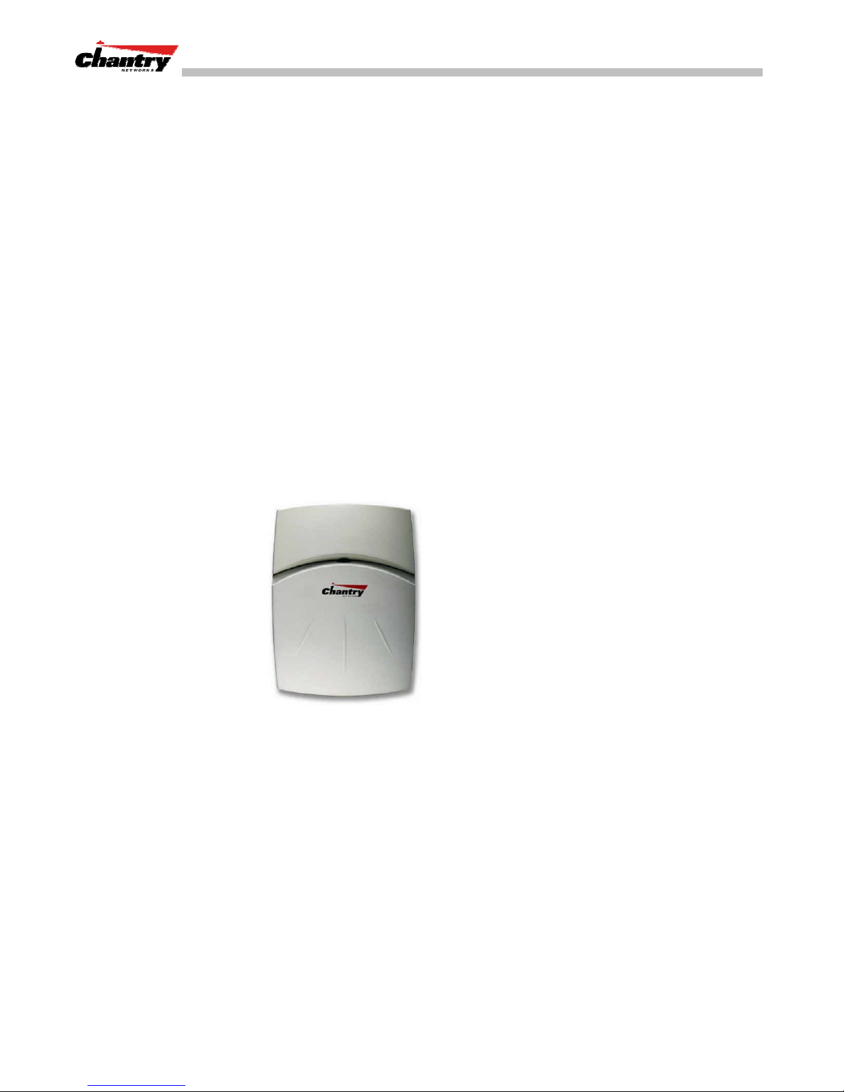
The Chantry BeaconPoint is a wireless LAN access point using the 802.11 wireless
standards that allow wireless functionality comparable to ethernet (802.11a, 802.11b
and 802.11g).
The BeaconPoint is provided with proprietary software that allows it to communicate
only with the BeaconMaster.
The BeaconPoint is physically connected to a LAN infrastructure with an IP
connection to a BeaconMaster. The BeaconPoint has no user interface. The only way
to communicate with a BeaconPoint is through the BeaconMaster.
All communication with the BeaconMaster is carried out using a UDP-based protocol
called CAPWAP Tunnelling Protocol (CTP) to encapsulate IP traffic from the
BeaconPoints and direct it to the BeaconMaster. The BeaconMaster decapsulates the
packets and routes them to the appropriate destinations, while managing sessions and
applying policy.
BeaconWorks User Guide – BeaconPoint: Startup
The BeaconPoint BP200 has two radios:
• a radio that supports the 802.11a standard.
The
provides up to 54 Mbps in the 5-GHz band. 802.11a uses an orthogonal frequency
division multiplexing encoding scheme rather than FHSS or DSSS.
• a radio that supports the 802.11g standard (and 802.11b).
The
GHz band. Because 802.11g uses the same communication frequency range as
802.11b (2.4 GHz), it is backwards compatible with 802.11b.
The
transmission rate of 11 Mbps (with a fallback to 5.5, 2 and 1 Mbps) in the 2.4 to
2.4835 GHz frequency band. The 802.11b standard uses direct-sequence spread
spectrum (DSSS).
Either radio on the BP200 can be enabled or disabled in the user interface.
Chantry Networks Inc. Copyright 2004. All rights reserved. BeaconWorks Rel 2.0 (051304) Page 30 of 134
802.11a standard
802.11g standard
is an extension to 802.11 that applies to wireless LANs and
applies to wireless LANs and provides 20+ Mbps in the 2.4
802.11b (High Rate)
Figure 6: The Chantry BeaconPoint
standard is an extension to 802.11 that specifies a
Page 31

BeaconWorks User Guide – BeaconPoint: Startup
The BP200 supports the full range of 802.11a:
5.15 to 5.25 GHz U-NII Low Band
5.25 to 5.35 GHz U-NII Middle Band
5.725 to 5.825 GHz U-NII High Band
New 5.470 GHz to 5.725 GHz Band
(when approved by FCC)
The U-NII bands (Unlicensed National Information Infrastructure) are three frequency
bands of 100 MHz each in the 5 GHz band designated for short-range, high-speed
wireless networking communication.
The BeaconPoint BP200 has two models:
• internal antenna (Model BP200s), internal dual (multimode) diversity
antennas
• external antenna (Model BP200e) (dual external antennas) RP-SMA
The BeaconPoint are powered in one of three ways:
Power Over Ethernet (PoE)
•
If your network is already set up with PoE, attach the LAN ethernet cable to the
RJ45 ethernet connector in the top of the BeaconPoint.
Power Over Ethernet: Adding PoE Injector
•
If your network is not set up with PoE, you can provide power to the ethernet cable
with a PoE injector. The PoE injector must be 802.3af compliant. The PoE injector
is not provided with the BeaconPoint.
Power by AC Adaptor
•
An AC adaptor is not provided with the BeaconPoint. If you wish to use one, the
specifications are:
BP200
– Input: 120-240 VAC, Output Voltage DC +6V, max
amps 1.50, max watts 10.
To use an adaptor, install the BeaconPoint within six feet of a wall outlet, attach
the adaptor to the BeaconPoint and then plug the adaptor into the wall outlet.
Note:
For a list of recommended and tested devices (PoE Injectors or AC adaptors)
for use with the BeaconPoint, contact Chantry Networks Customer Service, or go to
www.chantrynetworks.com/site/support.html.
The BeaconPoint has a mounting bracket for wall, ceiling or plenum mount, and
security hardware (an allen key and a spreading rivet with screw, described later).
Chantry Networks Inc. Copyright 2004. All rights reserved. BeaconWorks Rel 2.0 (051304) Page 31 of 134
Page 32
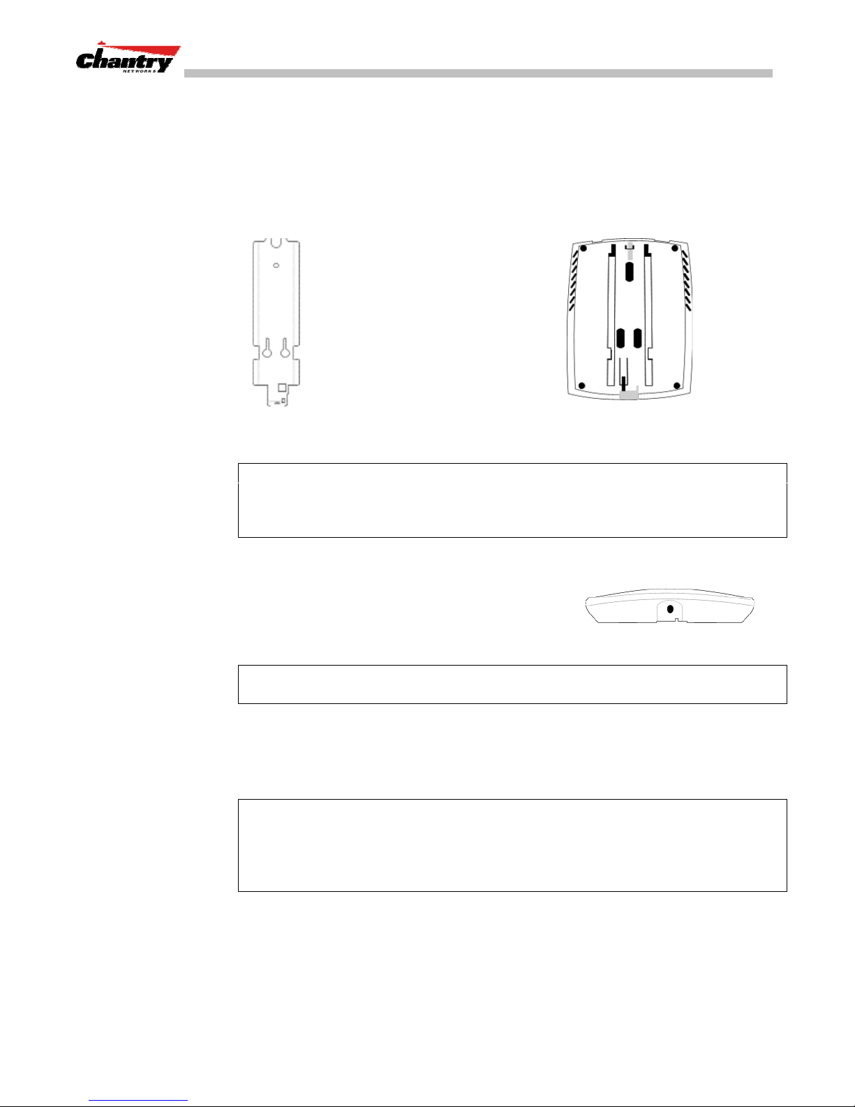
Installing the BeaconPoints
BeaconWorks User Guide – BeaconPoint: Startup
The steps to install the BeaconPoints are repeated here from the
Installation Guide
packed with the units. Keep the security instructions for future reference (along with
the allen key needed to remove the BeaconPoint from its mounting bracket).
1. Unpack the BeaconPoint from its shipment carton. Check that all parts are present,
using the
Installation Guide
packed with the unit.
2. Mount the BeaconPoint
wall bracket, using 3 screws.
Make sure the top of the bracket
is near the LAN ethernet cable
plug coming from the wall.
3. Press the back of the
BeaconPoint onto the bracket,
aligning it with the open notches
in the bracket.
BeaconPoint
wall bracket
Security Note #1:
Then slide it downwards
until it clicks into place.
Channel for allen key to spring clip
A small spring clip on the BeaconPoint case has now snapped into
↑
the bracket. To remove the BeaconPoint from the bracket, insert the allen key
(provided) into the small hole at the bottom of the bracket. Use the allen key to
depress the spring clip. Then slide the case up the bracket and lift off the BeaconPoint.
4. Insert the
plastic spreading rivet
through the
hole at the bottom of the bracket and into the
Opening for rivet
↓
BeaconPoint case. Then screw in the plastic
screw. This spreads the rivet and locks the case
to the bracket.
Security Note #2:
Opening for allen key
The spreading rivet prevents casual removal of the BeaconPoint.
↑
You will need a screwdriver to remove it.
5. Attach the LAN ethernet cable to the ethernet port of the BeaconPoint.
6. If you are using the optional power adaptor (rather that Power-over-Ethernet),
plug in the unit.
Note:
Before you power up the BeaconPoint (steps 5 or 6), you should first power up
the BeaconMaster, and then define the Registration Mode in the User Interface of the
BeaconMaster (
BeaconPoint Configuration
BP Registration
,
screen).
Powering up the BeaconPoint initiates its automatic discovery and registration process
described below. The parameters for this process should be set first. See next topic.
Chantry Networks Inc. Copyright 2004. All rights reserved. BeaconWorks Rel 2.0 (051304) Page 32 of 134
Page 33
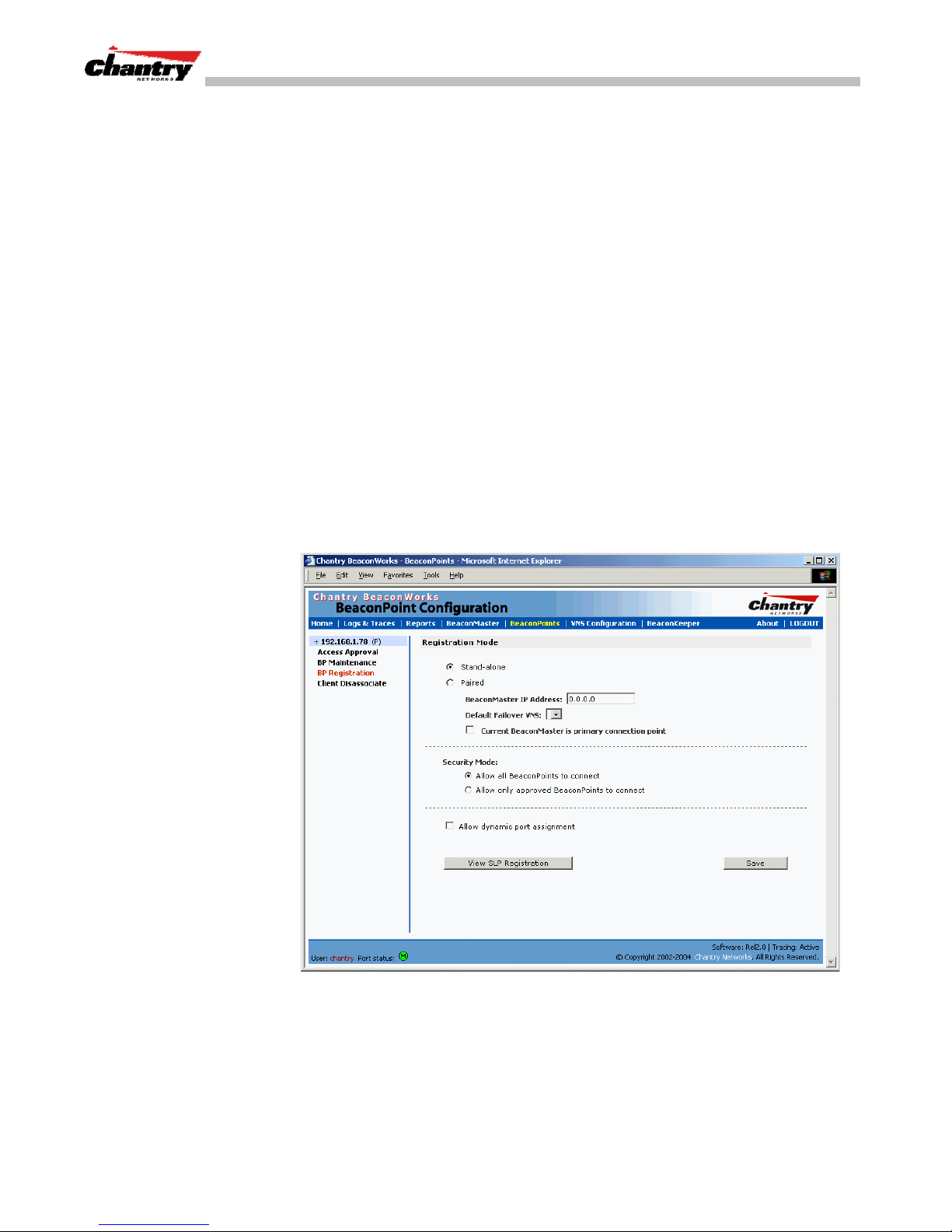
BeaconPoint: Registering
Setting Parameters for BeaconPoint Registration
Before the BeaconPoints are powered and begin their automatic process of
“Discovery” and “Registration”, you should define the parameters of this process.
This is done in the
In this screen you define the Security Mode: whether the BeaconMaster should
automatically allow all BeaconPoints to register, or whether only approved
BeaconPoints should be allowed.
This screen also controls the “Availability” function, whether this BeaconMaster is
paired with another BeaconMaster. If they are paired, then they share information
about BeaconPoints and if one BeaconMaster fails, the other can continue to provide
service availability. This is discussed in detail later in this Guide (BeaconMaster
Configuration: Availability).
Define the Security Mode for registering BeaconPoints
BeaconWorks User Guide – BeaconPoint: Startup
BeaconPoint Registration Mode
screen.
1. Select
BeaconPoints
tab in any screen.
2. In the left-hand list, click on
Mode
screen appears.
BP Registration
BeaconPoint Registration
. The
3. To
mode by default.)
To
Chantry Networks Inc. Copyright 2004. All rights reserved. BeaconWorks Rel 2.0 (051304) Page 33 of 134
Screen 13: BeaconPoint Configuration – BP Registration Mode
allow all
allow approved
BeaconPoints to connect, click this radio button. (The screen is in this
BeaconPoints
only
to connect, click on this radio button
During the “Registration” process, the BeaconMaster’s approval of the serial
number of the BeaconPoint depends on the security mode that has been set:
Page 34

BeaconWorks User Guide – BeaconPoint: Startup
Allow all
•
If the BeaconMaster does not recognize the serial number, it sends a default
configuration to the BeaconPoint.
If it recognizes the serial number, it sends the specific configuration (port and
binding key) set for that BeaconPoint.
Allow approved
•
If the BeaconMaster does not recognize the serial number, the operator is
prompted to create a configuration.
If it recognizes the serial number, it sends the configuration for that
BeaconPoint.
Note:
It may be advisable, for the initial set up of the network, to select the “Allow
All” option here. This is the most efficient way to get a large number of BeaconPoints
registered with the BeaconMaster.
However, after that, you may want to reset this option to “Allow Approved”, so that
no unapproved BeaconPoints would be able to connect. You can modify the status of
an unapproved BeaconPoint in the
BeaconPoint Configuration: BP Maintenance
screen described later in this Guide.
4. To save the above parameters, click the
Note:
The remaining functions in this screen are part of the “Availability” feature,
Save
described later in this Guide. Whether this BeaconMaster is
Paired
or is
with another BeaconMaster, and whether it is the Primary or Secondary
connection, is part of the “Availability” feature. The
assignment
checkbox is also used as part of the “Availability” feature.
Now you can go back to the BeaconPoints and power them on. They will begin the
automatic Discovery and Registration sequence.
Discovery and Registration: The DHCP and SLP Solution
Before you can begin to register the BeaconPoints with the BeaconMaster, you must
ensure that the DHCP server on your network supports Option 78. The BeaconPoints
rely on these to locate the BeaconMaster during the discovery process, as explained
below.
The solution to centrally configuring BeaconPoints, and to mass deployment, is to
take advantage of two services that are present on most networks: DHCP and SLP.
DHCP (Dynamic Host Configuration Protocol), is the standard means of providing IP
addresses dynamically to devices on a network.
button.
Stand-alone
Allow dynamic port
(the default)
SLP (Service Location Protocol) is a means of allowing client applications to
network services without knowing their location beforehand. Devices advertise their
services, using a
information from Service Agents and creates a central repository.
A device that is searching for a service makes use of the SLP
information from Service Agents or Directory Agents. DHCP Option 78 returns a list
of IP addresses of Directory Agents.
Chantry Networks Inc. Copyright 2004. All rights reserved. BeaconWorks Rel 2.0 (051304) Page 34 of 134
Service Agent
. In larger installations, a
Directory Agent
User Agent
discover
collects
to retrieve
Page 35

BeaconWorks User Guide – BeaconPoint: Startup
Meanwhile, the active BeaconMaster has management software that has registered
itself as a service. When a BeaconMaster starts up, it queries the DHCP server for
Option 78. It registers with the Directory Agents as service type “Chantry”.
This information enables the BeaconPoint to discover the location of the
BeaconMaster.
The BeaconPoint’s Discovery Process and LED Sequence
As soon as the BeaconPoint is powered and connected to the LAN, it begins its
automatic process to discover and register with the BeaconMaster.
For the BP200 the Status LED in the centre also indicates power. The Status LED is
dark when unit is off and is green (solid) when the BP has completed discovery and is
operational.
BP200
LED
←
Status LED
→
↑
Left LED: Right LED:
2.4 GHz radio 5 GHz radio
activity activity
↓
↑
The BeaconPoint boot sequence is described below:
1. When powered on, the BeaconPoint status LED turns from dark to green briefly.
Status LED: green (solid) then to dark before beginning boot sequence.
2. [available in Release 2.0 only] The BeaconPoint performs a self-test.
[available in Release 2.0 only]
Status LED: red (solid) if POST failed.
3. The “Discovery” mode: the BeaconPoint sends a request to the DHCP server on
the enterprise network for the location of the BeaconMaster. (This is
accomplished through a combination of Service Location Protocol (SLP) and
DHCP, as described above.)
Status LED: orange (solid) while searching (“Discovery”)
Status LED: red-orange (alternate blink) if DHCP server not found on network
Status LED: green-orange (alternate blink) if SLP issues in failed discovery.
4. The BeaconPoint “learns” the IP address of the BeaconMaster,
Status LED: orange (blink) when IP address successfully obtained
(“Registration” process underway)
Status LED: red (blink) if “Registration” fails
5. The BeaconPoint sends its serial number (a unique identifier that is hard coded
during manufacture) to the BeaconMaster.
Status LED: green (blink) when BeaconPoint finds BeaconMaster (“Standby”
status)
6. The BeaconMaster sends the BeaconPoint a port IP address and a binding key, as
follows:
• If the BeaconMaster does not recognize the serial number, it sends a default
Chantry Networks Inc. Copyright 2004. All rights reserved. BeaconWorks Rel 2.0 (051304) Page 35 of 134
configuration to the BeaconPoint.
Page 36
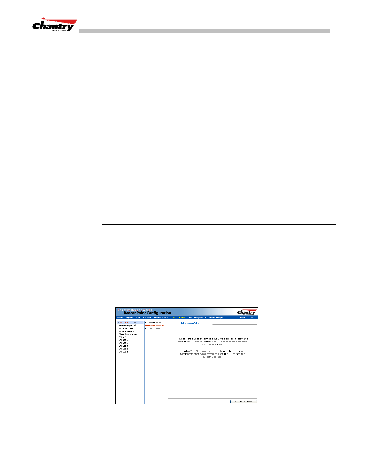
BeaconWorks User Guide – BeaconPoint: Startup
• If it does recognize the serial number, it sends the specific configuration (port
and binding key) set for that BeaconPoint.
The BeaconMaster also adds the BeaconPoint to its database.
Status LED: green (blink) when BeaconPoint finds BeaconMaster (“Standby”
status)
7. When the binding key is received, the BeaconPoint’s status changes from
“Standby” to “Active”. It becomes active and is enabled to transmit data traffic.
LED: green steady (“Active”)
When the BeaconPoint has wireless traffic, you will see a green blink on the traffic
LED. On the BP200, the left LED indicates the traffic LED for activity on the 2.4
GHz radio, while the right LED indicates activity on the 5 GHz radio.
Once a BeaconPoint is registered with a BeaconMaster:
• it appears in the side list in the
BeaconPoint Configuration: Properties
where you can modify the properties and radio parameters.
• its two radios appear as available choices in the
Topology
screen, when you are setting up a VNS (for up to four VNS for each
radio).
Note:
Before a registered BeaconPoint can handle wireless traffic, you must set up a
VNS definition, and assign the BeaconPoint’s radios to a VNS. See
Configuration
.
BeaconPoint: Configuring Properties and Radios
View and modify properties of registered BeaconPoints
1. Select the
screen appears, with a list of registered BeaconPoints.
2. Highlight the appropriate BeaconPoint in the list.
3. If the selected BeaconPoint is running Release 1.1 software, the properties cannot
be modified. You will see the following message:
BeaconPoints
tab in any screen. The
screen,
Virtual Network Configuration:
Virtual Network
BeaconPoint Configuration
Screen 14: BeaconPoint Configuration: Message R1.1 version of BP software
To schedule a software upgrade for the BeaconPoint, use the
Configuration: BP Maintenance
Chantry Networks Inc. Copyright 2004. All rights reserved. BeaconWorks Rel 2.0 (051304) Page 36 of 134
BeaconPoint
screen, described later in this guide.
Page 37
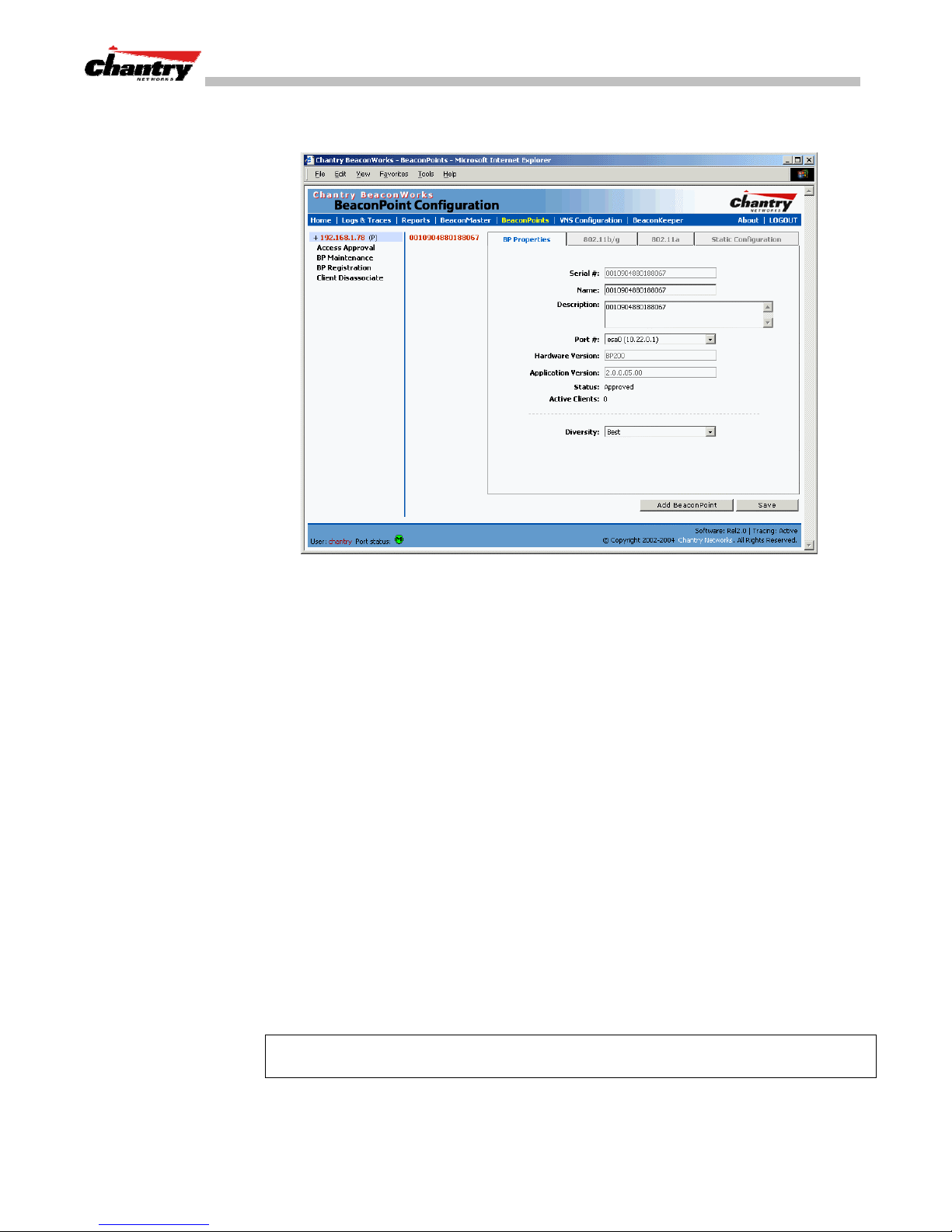
BeaconWorks User Guide – BeaconPoint: Startup
4. For a BeaconPoint running Release 2.0 software, click on the
to view basic information about the highlighted BeaconPoint.
BP Properties
tab
Screen 15: BeaconPoint Configuration – Properties
5. To modify the default information about a selected BeaconPoint, key in
information in the following fields (where appropriate):
Serial #
Name
(Display only) A unique identifier set during manufacture.
Change the serial number to a unique descriptive name that
more easily identifies the BeaconPoint.
Description
Port #
Available for descriptive comments (optional).
From the drop-down list, select the ethernet port through
which the BeaconPoint can be reached.
Hardware Version
Application Version
Status
(Display only) Current version of the BeaconPoint hardware.
(Display only) Current version of the BeaconPoint software.
(Display only) “Approved” = BeaconPoint has received its
binding key from the BeaconMaster after the Discovery
process. “Pending” = binding key not yet received.
Active Clients
(Display only) The number of wireless devices currently
active on the BeaconPoint.
Diversity
From the drop-down list, select “Best,” for the best signal
from both antennas, or “Left” or “Right” to choose either of
the two diversity antennas.
Note:
You can modify the status of a BeaconPoint (for example from “Pending” to
“Approved”) in the
3. To save the modified information, click on the
Chantry Networks Inc. Copyright 2004. All rights reserved. BeaconWorks Rel 2.0 (051304) Page 37 of 134
Access Approval
screen.
Save
button.
Page 38
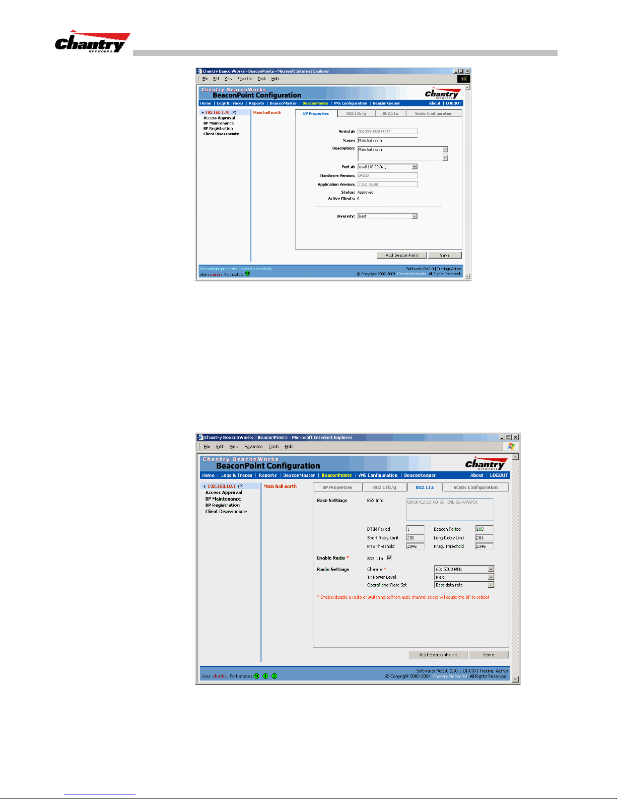
BeaconWorks User Guide – BeaconPoint: Startup
Screen 16: BeaconPoint Configuration – Properties (after modifications)
View and modify the radio settings of registered BeaconPoints
1. Select the
BeaconPoints
tab in any screen. The
BeaconPoint Configuration
screen appears, with a list of registered BeaconPoints.
2. Highlight the appropriate BeaconPoint in the list. Then click on the appropriate
radio tab:
802.11a
•
802.11 b/g
•
(5 GHz radio)
(2.4 GHz radio)
The screen displays the default radio settings for each radio on the BeaconPoint.
Chantry Networks Inc. Copyright 2004. All rights reserved. BeaconWorks Rel 2.0 (051304) Page 38 of 134
Screen 17: BeaconPoint Configuration – Radio 802.11a (5 GHz)
Page 39
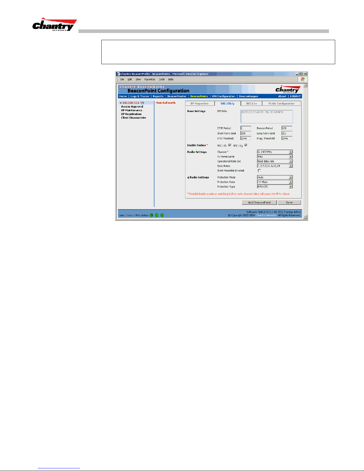
BeaconWorks User Guide – BeaconPoint: Startup
Note:
If this radio has been assigned to a VNS (or up to four VNSs), the VNS names
and MAC addresses will be displayed in the Base Settings area. (See
Configuration
.)
Virtual Network
Screen 18: BeaconPoint Configuration – Radio 802.11b/g (2.4 GHz)
3. Modify these
BSS Info
DTIM
Beacon Period
Short Retry Limit
Long Retry Limit
RTS Threshold
Frag. Threshold
Base Settings
(Display only) After VNS configuration, the Basic Service
Set (BSS) area displays the MAC address on the
BeaconPoint for each VNS and the SSIDs of the VNSs to
which this radio has been assigned.
Delivery Traffic Indication Message period. Default is 1.
The time units between beacon transmissions. Default is
100.
The maximum number of transmission attempts of a frame
that is less than or equal to the RTS Threshold, before a
failure condition is indicated. Default is 200.
The maximum number of transmission attempts of a frame
that is greater than the RTS Threshold, before a failure
condition is indicated. Default is 201.
Request To Send Threshold, the size of a data unit below
which an RTS/CTS (RTS/Clear to Send) handshake is not
performed. Default is 2346.
The Fragmentation Threshold, the maximum size of a packet
or data unit that can be delivered. Default is 2346.
where appropriate.
Enable Radios
Chantry Networks Inc. Copyright 2004. All rights reserved. BeaconWorks Rel 2.0 (051304) Page 39 of 134
Click checkbox on for each radio.
Page 40

Radio Settings:
BeaconWorks User Guide – BeaconPoint: Startup
Channel
Tx Power Level
Operational Rate Set
Basic Rates
(Drop-down list) The wireless channel that the BeaconPoint
should use to communicate with wireless devices.
802.11a 802.11b/g
Auto Auto
36: 5180 MHz 1: 2412 MHz
40: 5200 MHz 2: 2417 MHz
44: 5220 MHz 3: 2422 MHz
48: 5240 MHz 4: 2437 MHz
52: 5260 MHz 5: 2432 MHz
56: 5280 MHz 6: 2437 MHz
60: 5300 MHz 7: 2442 MHz
64. 5320 MHz 8: 2447 MHz
149: 5745 MHz 9: 2452 MHz
153: 5765 MHz 10: 2457 MHz
157: 5785 MHz 11: 2462 MHz
161: 5805 MHz
165: 5825 MHz
(Drop-down list) Min, 13%, 25%, 50%, Max.
(Drop-down list) in Mbps
A: Best data rate, 6, 9 12,18, 24, 36, 48, 54
B/G: Best data rate, 1, 2, 5.5, 11, 6, 9 12,18, 24, 36, 48, 54
(for b radio only) Select a set of basic rates from the dropdown list. The best data rate from the set will be used for
current conditions (power vs range)
Short Preamble Invoked
g Radio Settings:
Protection Mode
Protection Rate
Protection Type
4. To save the modified information, click on the
Note:
In Release 2.0, a number of the properties of each radio on a BeaconPoint can
be modified (in the
BeaconPoint Configuration
the BeaconPoint.
However, modifying the following properties will trigger a reboot of the BeaconPoint:
• enabling or disabling either radio
• changing the radio channel between “Auto” and any fixed channel number.
BeaconPoint: Adding Manually
Add and register a BeaconPoint manually
1. Select the
Add BeaconPoint
BeaconPoint
Click checkbox on to enable.
(Drop-down list) None, Auto (default), Always
(Drop-down list) in Mbps: 1, 2, 5.5, 11 (default)
(Drop-down list) CTS (Clear To Send),
RTS CTS (Request To Send, Clear To Send) – default.
Save
button.
screen) without requiring a reboot of
tab. In the
button. The
BeaconPoint Properties
BeaconPoint Configuration
screen, click on the
subscreen appears.
Chantry Networks Inc. Copyright 2004. All rights reserved. BeaconWorks Rel 2.0 (051304) Page 40 of 134
Page 41
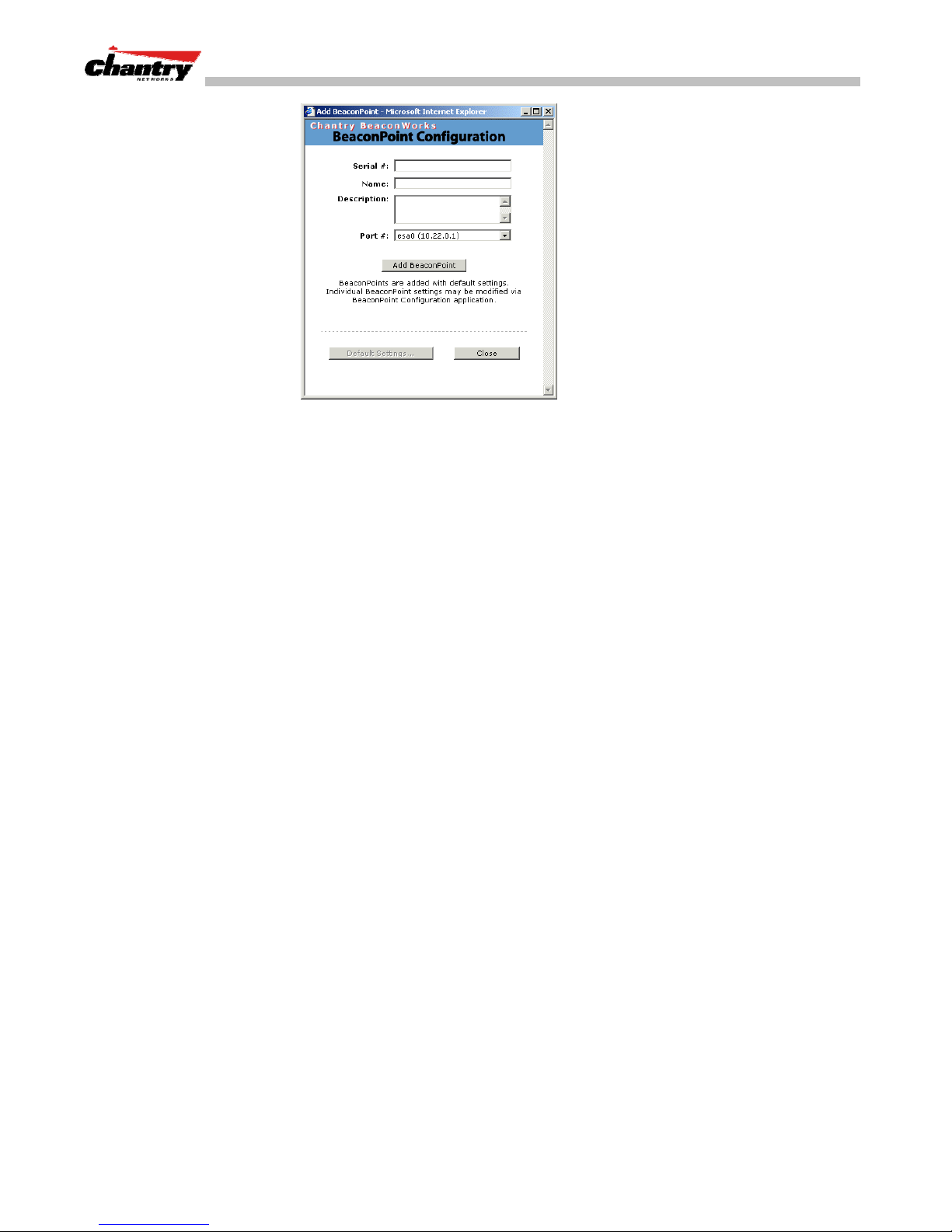
BeaconWorks User Guide – BeaconPoint: Startup
Screen 19: BeaconPoint Configuration – Add BeaconPoint
3. Key in, or select from the drop-down list, information in the following fields:
Serial #
Name
Description
Port #
4. To add the BeaconPoint, click the
To return to the previous screen, click
A unique identifier set during manufacture.
A unique name for the BeaconPoint.
Available for descriptive comments (optional).
The ethernet port through which the BeaconPoint can be reached
Add BeaconPoint
Close
.
The BeaconPoint is added with default settings. To modify these settings, use the
BeaconPoint Configuration
screens described earlier. You can modify the properties
and the settings for each radio on the BeaconPoint.
BeaconPoint Radios on a VNS
Before a registered BeaconPoint can handle wireless traffic, you must set up a VNS
definition, and assign one or both of the BeaconPoint’s radios to a VNS. See
Network Configuration
After you have set up
section for details.
Virtual Network Configuration
BeaconPoint radios to a VNS (or up to four VNSs), the VNS names and the MAC
addresses are displayed in the Base Settings: “BSS Info” area.
BeaconPoint Static Configuration: Branch Office Deployment
button
.
Virtual
definitions and assigned the
The BeaconPoint static configuration feature provides BeaconWorks capability for a
network with the central office / branch office model.
In the branch office scenario, BeaconPoints are installed in remote sites, while the
BeaconMaster is in the central office. The BeaconPoints require the capability to
interact both in the local site network and in the central network.
To achieve this, the BeaconPoint’s automatic process of discovery and registration
with the BeaconMaster is disabled, and a static configuration is used instead.
Chantry Networks Inc. Copyright 2004. All rights reserved. BeaconWorks Rel 2.0 (051304) Page 41 of 134
Page 42
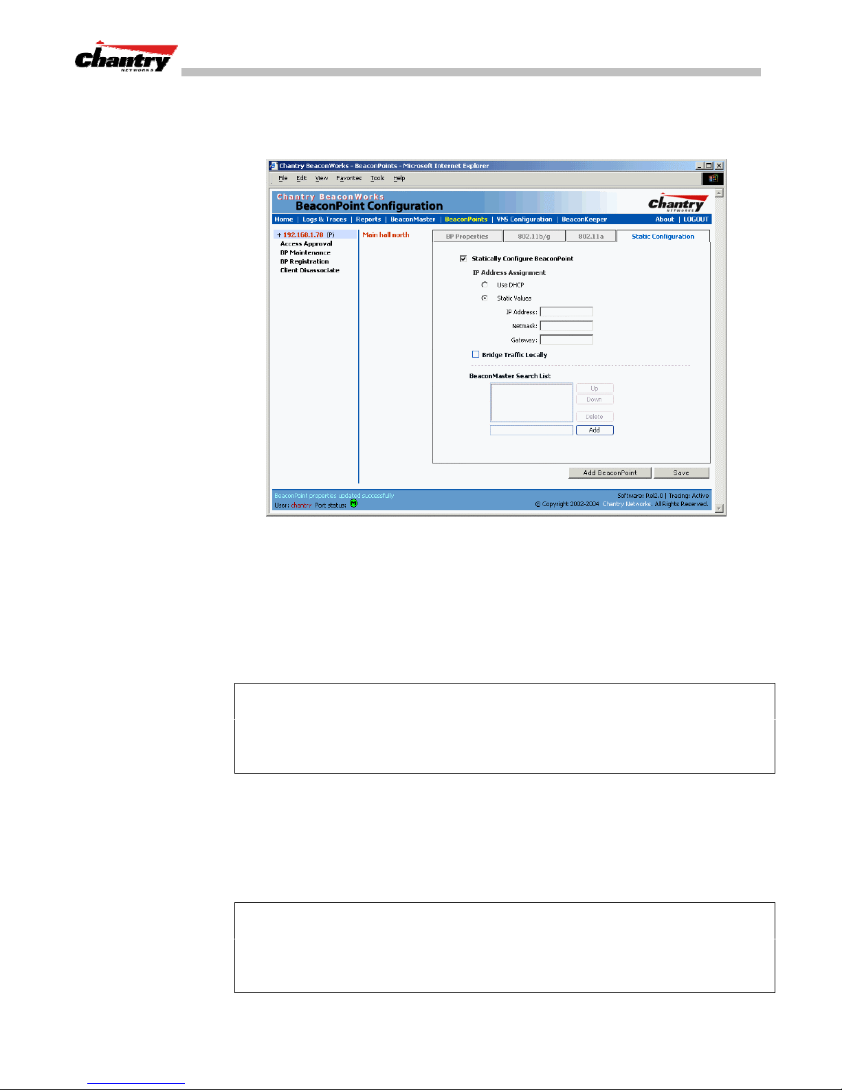
BeaconWorks User Guide – BeaconPoint: Startup
Set up a BeaconPoint with static configuration
1. Select the
click on the
BeaconPoint
Static Configuration
tab in any screen. In the
tab. The
BeaconPoint Properties
Static Configuration
screen,
screen appears.
Screen 20: BeaconPoint Configuration: Static Configuration
2. To enable static configuration of the BeaconPoint, click the
BeaconPoint
checkbox on.
Statically Configure
3. Select one of the two methods of IP address assignment for the BeaconPoint:
DHCP
• to enable
, click the radio button on (default),
• to specify the IP address of the BeaconPoint, click the
or
Static Values
radio
button on and fill in the IP Address, Subnet Mask, and Gateway.
Note:
For first time deployment of the BeaconPoint for a Branch Office scenario, it is
recommended that you use DHCP initially on the central office network to obtain an
IP address for the BeaconPoint.
Then enter these values in the
Static Configuration
screen for this BeaconPoint and
save the configuration.
4. Add a BeaconMaster IP address to the list of BeaconMasters. Click in the entry
field and key in the address of the BeaconMaster that will control this
BeaconPoint. This allows the BeaconPoint to bypass the discovery process. If this
field is not filled in, the BeaconPoint will use SLP to discover a BeaconMaster.
Save
5. To save the static configuration, click on the
Note:
In a “Branch Office” scenario, where the BeaconPoint is configured statically to
button.
function on a local network whose MTU is lower than 1500, a mechanism on the
BeaconMaster automatically adjusts the MTU size to prevent packet fragmentation.
The MTU is set in the
BeaconMaster Configuration – IP Addresses / Interfaces
screen
and should not be changed.
Chantry Networks Inc. Copyright 2004. All rights reserved. BeaconWorks Rel 2.0 (051304) Page 42 of 134
Page 43

BeaconWorks User Guide – Virtual Network Services (VNS): Overview
Virtual Network Services (VNS): Overview
Virtual Network Services (VNS) are the key to the advantages that the Chantry
BeaconWorks system has to offer. This technique provides a versatile means of
mapping wireless networks to the topology of an existing wired network.
When you set up a VNS on the BeaconMaster, you are defining a subnet for a group
of wireless device users. This VNS definition creates a virtual IP subnet where the
BeaconMaster acts as a default gateway to wireless devices.
Before you begin to define a VNS, you should have determined:
user access plan
•a
• the RADIUS attributes that support the user access plan
• the location and identity of the BeaconPoints that will be used on the VNS
• the routing mechanism to be used on the VNS
• the network addresses that the VNS will use
• the type of authentication for wireless device users on the VNS
for both individual users and user groups
• the specific filters to be applied to the defined users and user groups to control
network access
• what privacy mechanisms should be employed between the BeaconPoints and the
wireless devices.
• whether the VNS is to be used for voice traffic.
user access plan
The
should analyze the enterprise network and identify which users
should have access to which areas of the network. What areas of the network should
be separated? Which users can go out the World Wide Web?
The BeaconWorks system relies on authenticating users via a RADIUS server (or
other authentication server). To make use of this feature, you will, of course, require
such an authentication server on the network. Make sure that the server’s database of
registered users, with login identification and passwords, is current.
Note
: It is possible to deploy BeaconWorks without a RADIUS server (and without
the authentication of users on the network). In that scenario, select
network assignment (in the
Authentication
in the
screen, click on the
Topology
screen described later in this section) and then,
None
radio button. That means there is no
SSID
as the
authentication of users, but BeaconWorks is otherwise operational.
The user access plan should also identify the user groups in your enterprise, and the
business structure of the enterprise network. You could identify users for various
purposes, as in these examples:
• department (such as Engineering, Sales, Finance)
• role (such as student, teacher, library user)
• status (such as guest, administration, technician).
For each user group, you should set up a Filter ID attribute in the RADIUS server, and
then associate each user in the RADIUS server to at least one Filter ID name.
Chantry Networks Inc. Copyright 2004. All rights reserved. BeaconWorks Rel 2.0 (051304) Page 43 of 134
Page 44

What is a VNS?
BeaconWorks User Guide – Virtual Network Services (VNS): Overview
Chantry enables you to define specific filtering rules, by Filter ID attribute, that will
be applied to user groups to control network access.
A VNS is an IP subnet that is especially designed to enable Chantry BeaconPoints to
interact with wireless devices.
In many ways, a VNS is very similar to a regular IP subnet. However, it has the
following required features:
1. Each VNS is assigned a unique identifier.
2. Each VNS is assigned an SSID. These do not have to be unique.
3. Each VNS is assigned a range of IP addresses for wireless devices. All the
wireless devices share the same IP address prefix (the part of the IP address that
identifies the network and subnet).
The IP addresses of the wireless devices are assigned dynamically by the
BeaconMaster’s DHCP server within the assigned range.
(These IP addresses are not “virtual”. They are regular IP addresses, and are
unique over the network. These IP addresses are
advertised
to other hosts on the
network so that they can exchange traffic with the wireless devices in the VNS.)
Note:
Alternatively, you can allow the enterprise network’s DHCP server to provide
the IP addresses for the VNS, by enabling
4. A single overall filtering policy applies to all the wireless devices within the VNS.
However, further filtering can be applied when the wireless user is authenticated
by the RADIUS server.
5. When the BeaconMaster creates the VNS, it also creates a
that VNS.
Topology of a VNS: Overview
The first step in setting up a VNS is configuring the topology in the
The type of network assignment determines all the other factors of the VNS. The
options for network assignment are:
SSID
•
:
• has Captive Portal authentication, or no authentication.
• requires restricted filtering rules before authentication and, after
authentication, filtering rules for group Filter IDs.
• is used for a VNS supporting wireless voice traffic (QoS).
• is used for a VNS supporting third-party APs.
• has WEP privacy.
DHCP Relay
in the Topology screen.
virtual IP subnet
Topology
screen.
for
AAA
•
• has 802.1x authentication
• requires filtering rules for group Filter IDs and default filter.
• has WEP and WPA privacy.
Chantry Networks Inc. Copyright 2004. All rights reserved. BeaconWorks Rel 2.0 (051304) Page 44 of 134
(Authentication, Authorization and Accounting).
Page 45

BeaconWorks User Guide – Virtual Network Services (VNS): Overview
The next step to assign the available BeaconPoints (by radio) to the VNS.
Multi-SSID: BeaconPoint radios on more than one VNS
In Release 2.0, each radio on a BeaconPoint BP200 can participate in up to four
VNSs, for a total of eight VNSs per BeaconPoint. The
of registered BeaconPoints with a checkbox for each radio. A BeaconPoint radio will
appear in the list as available for VNS assignment until it has been assigned to four
VNSs. After that, it will no longer appear in the list.
After a VNS definition has been saved, the BeaconMaster updates this information on
the BeaconPoint. Each radio acquires up to four SSIDs (one for each VNS it is part
of), and broadcasts these during beacon transmission (unless the beacon is suppressed
in the VNS topology screen).
Topology
screen displays a list
You can view (in the
BeaconPoint Configuration
which each radio has been assigned.
Other network parameters for the VNS topology
Topology
In the
area of VNS configuration, you also define other aspects of the VNS,
such as the parameters for DHCP for IP address assignment. You might also configure
this VNS for management traffic only, or for Third-Party Access Points, or for Voice
Traffic. (These are described in detail later in this Guide.)
Network Assignment and Authentication for a VNS
The second step is to configure the authentication mechanism for the VNS. The
authentication mechanism depends on the network assignment.
Authentication with SSID Network Assignment
SSID
If
•
•
was selected, there are two authentication options:
None
: The wireless device connects to the network, but can only access specified
network destinations (those defined in the
Filtering
Captive Portal
). No authentication is performed.
: The wireless device connects to the network, but can only access
specified network destinations (those defined in the
described in
Filtering
). One of those destinations is a web page logon screen (the
portal in which he is captive), where the user must input an ID and a password.
This identification is sent by the BeaconMaster to the RADIUS server for
authentication. Four authentication types are supported by BeaconWorks for
Captive Portal:
screen) a list of defined VNSs to
Non-Authenticated Filter
described in
Non-Authenticated Filter
• PAP (Password Authentication Protocol)
• CHAP (Challenge Handshake Authentication Protocol)
• MS CHAP (Windows-specific version of CHAP)
• MS CHAP v2 (Windows-specific version of CHAP, version 2)
Note:
For Captive Portal, the RADIUS server must support the selected authentication
type: PAP, CHAP (RFC2484), MS-CHAP (RFC2433), MS-CHAPv2 (RFC2759).
Chantry Networks Inc. Copyright 2004. All rights reserved. BeaconWorks Rel 2.0 (051304) Page 45 of 134
Page 46

BeaconWorks User Guide – Virtual Network Services (VNS): Overview
Authentication with AAA (802.1x) Network Assignment
AAA (802.1x)
If
was selected, the wireless device user requesting network access via
BeaconWorks must first be authenticated. The wireless device’s client utility must
support 802.1x. The user’s request for network access along with login identification
or user profile will be forwarded by the BeaconMaster to a RADIUS server.
BeaconWorks supports these authentication types:
• EAP-TLS Extensible Authentication Protocol - Transport Layer Security that relies
on client-side and server-side certificates to perform authentication and can be
used to dynamically generate user-based and session-based WEP keys.
• EAP-TTLS (EAP with Tunneled Transport Layer Security) is an extension of
EAP-TLS to provide certificate-based, mutual authentication of the client and
network through an encrypted tunnel, as well as to generate dynamic, per-user,
per-session WEP keys. Unlike EAP-TLS, EAP-TTLS requires only server-side
certificates.
• PEAP (Protected Extensible Authentication Protocol) is a standard to authenticate
wireless LAN clients without requiring them to have certificates. In PEAP
authentication, first the user authenticates the authentication server, then the
authentication server authenticates the user.
Note:
For 802.1x, the RADIUS server must support RADIUS extensions (RFC2869).
If the RADIUS servers sends an “access-accept” message to the BeaconMaster, the
BeaconMaster’s DHCP server assigns the device its IP address and allows network
access controlled by the filtering rules defined for the specific Filter ID associated
with the wireless device user.
RADIUS Server: Location and Redundancy
Both Captive Portal and AAA (802.1x) authentication mechanisms in BeaconWorks
rely on a RADIUS server on the enterprise network.
In BeaconWorks Release 2.0, up to three RADIUS servers can be identified and
prioritized on the BeaconMaster. This means that in the event of a failover of the
active RADIUS server, the BeaconMaster will poll the other servers in the list for a
response.
Filtering for a VNS: How it works
The Chantry VNS capability provides a technique to apply policy, to allow different
network access to different groups of users. This is done by packet filtering.
After setting up the authentication, the next step is to define the filtering rules for the
filters that apply to your network and the VNS you are setting up.
Three types of filters are applied by the BeaconMaster in the following order:
1. Non-Authenticated filter, with filtering rules that apply before authentication, to
control network access and to direct users to a Captive Portal web page for login.
2. Group filters (by Filter ID) for designated user groups, to control access to certain
areas of the network, with names that match defined RADIUS Filter ID attributes.
3. Default filter, to control access if there is no matching Filter ID for a user.
Chantry Networks Inc. Copyright 2004. All rights reserved. BeaconWorks Rel 2.0 (051304) Page 46 of 134
Page 47

BeaconWorks User Guide – Virtual Network Services (VNS): Overview
Within each type of filter, you define a sequence of filtering rules. This sequence must
be carefully planned and arranged in the order that you want them to take effect. You
define each rule to either
allow
or
deny
traffic in either direction:
• “In”: from a wireless device in to the network
• “Out”: from the network out to the wireless unit.
Note:
The final rule in any filter should be a catch-all for any traffic that did not
match a filter. This final rule should either “allow all” or “deny all” traffic, depending
on the requirements for network access. For example, the final rule in a
Authenticated Filter
for Captive Portal is typically “deny all”. A final “allow all” rule
Non-
in a Default Filter will ensure that a packet is not dropped entirely if no other match
can be found.
Each rule can be based on any
one
of the following:
• destination IP address, or any IP address within a specified range that is on the
network subnet (as a wildcard)
• ports, by number and range
• protocols (UDP, TCP, etc.)
This is how the BeaconMaster software filters traffic:
1. The BeaconMaster software attempts to match each packet of a VNS to the
filtering rules that apply to the wireless device user.
2. If a filtering rule is matched, the operation (allow or deny) is executed.
3. The next packet is fetched for filtering.
The filtering sequence depends on the type of authentication:
No authentication (network assignment by SSID)
•
Only the Non-Authenticated filter will apply. Specific network access can be
defined. Since there will be no authentication, the final rule should be “deny all”.
Authentication by Captive Portal (network assignment by SSID)
•
The Non-Authenticated filter will apply before authentication. Specific network
access can be defined. The filter should also include a rule to allow all users to get
as far as the Captive Portal webpage where the user can enter login identification
for authentication. When authentication is returned, then the Filter ID group filters
are applied. If no Filter ID matches are found, then the Default filter is applied.
Authentication by AAA (802.1x)
•
Since users have already logged in and have been authenticated, there is no need
for a Non-Authenticated filter. When authentication is returned, then the Filter ID
group filters are applied. For AAA, a VNS can have a subgoup with Login-LATgroup ID that has its own filtering rules. If no Filter ID matches are found, then the
Default filter is applied.
Privacy on a VNS: Overview of WEP and WPA
Privacy is a mechanism that protects data over wireless and wired networks, usually
by encryption techniques.
Chantry Networks Inc. Copyright 2004. All rights reserved. BeaconWorks Rel 2.0 (051304) Page 47 of 134
Page 48
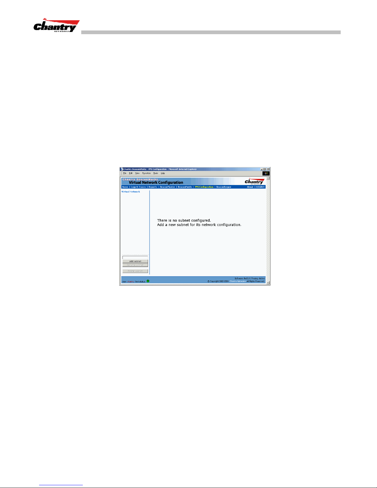
BeaconWorks supports the Wired Equivalent Privacy (WEP) standard common to
conventional access points. WEP provides data confidentiality services by encrypting
the data sent between wireless nodes. Each node must use the same encryption key.
For a VNS with AAA network assignment, BeaconWorks also provides Wi-Fi
Protected Access (WPA) privacy, a solution that adds authentication and enhanced
WEP encryption with key management. WPA is available in Enterprise Mode (which
specifies 802.1x authentication and requires an authentication server) or in Pre-Shared
Key mode (which relies on a shared secret). Encryption is by Temporal Key Integrity
Protocol (TKIP), which changes the encryption key after a specified interval.
Setting up a new VNS
BeaconWorks User Guide – Virtual Network Services (VNS): Overview
Click on the
Configuration
Virtual Network Configuration
tab in any screen. The
screen appears. For a new BeaconWorks installation, where no VNS
has yet been defined, the screen is blank, except for the
Screen 21: Virtual Network Configuration: Before any VNS definitions
Create a subnet (VNS)
1. In the entry field above the
Add subnet
button, key in a name that will uniquely
identify the new VNS.
Add subnet
Virtual Network
function.
2. Click on the
Topology
3. Highlight the name of the subnet you wish to configure. Its parameters can be
configured now in the
Chantry Networks Inc. Copyright 2004. All rights reserved. BeaconWorks Rel 2.0 (051304) Page 48 of 134
Add subnet
screen appears.
Topology
button. The name appears in the left-hand list. The
screen.
Page 49
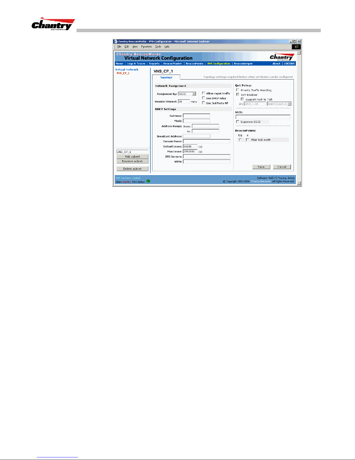
BeaconWorks User Guide – Virtual Network Services (VNS): Overview
Screen 22: Virtual Network Configuration: Topology for a new VNS Subnet
Configure the new VNS (overview of basic steps)
1. Select the network assignment mechanism from the
Assignment by
drop-down
list:
SSID
•
AAA
•
2. In the
SSID
box at the right, key in the SSID that the wireless devices will use to
access the BeaconPoint.
3. Select the
of available
BeaconPoints
BeaconPoints
(by radio) to be assigned to this VNS. The displayed list
has a checkbox for each radio on the BeaconPoint.
Each radio on a BeaconPoint can be assigned to a maximum of four VNSs. When
this maximum is reached, the radio will no longer be available in this list.
4. Configure other options for this VNS: Allow Management Traffic, Use DHCP
Relay, Use 3rd Party APs, or Enable Priority Traffic Handling.
5. Define the DHCP settings for this VNS.
Save
6. To save the new VNS Topology, click on the
button.
When the new Topology has been saved, the screen changes to display tabs for
Authentication, Filtering
and
Privacy
, for configuring these aspects of the new VNS.
The next sections explain several scenarios for possible VNS configurations:
• VNS for Captive Portal: Network Assignment by SSID and Authentication by
Captive Portal
• VNS with no Authentication: Network Assignment by SSID and no Authentication
• VNS for Voice Traffic
• VNS with 802.1x Authentication: Network Assignment by AAA (802.1x)
Chantry Networks Inc. Copyright 2004. All rights reserved. BeaconWorks Rel 2.0 (051304) Page 49 of 134
Page 50
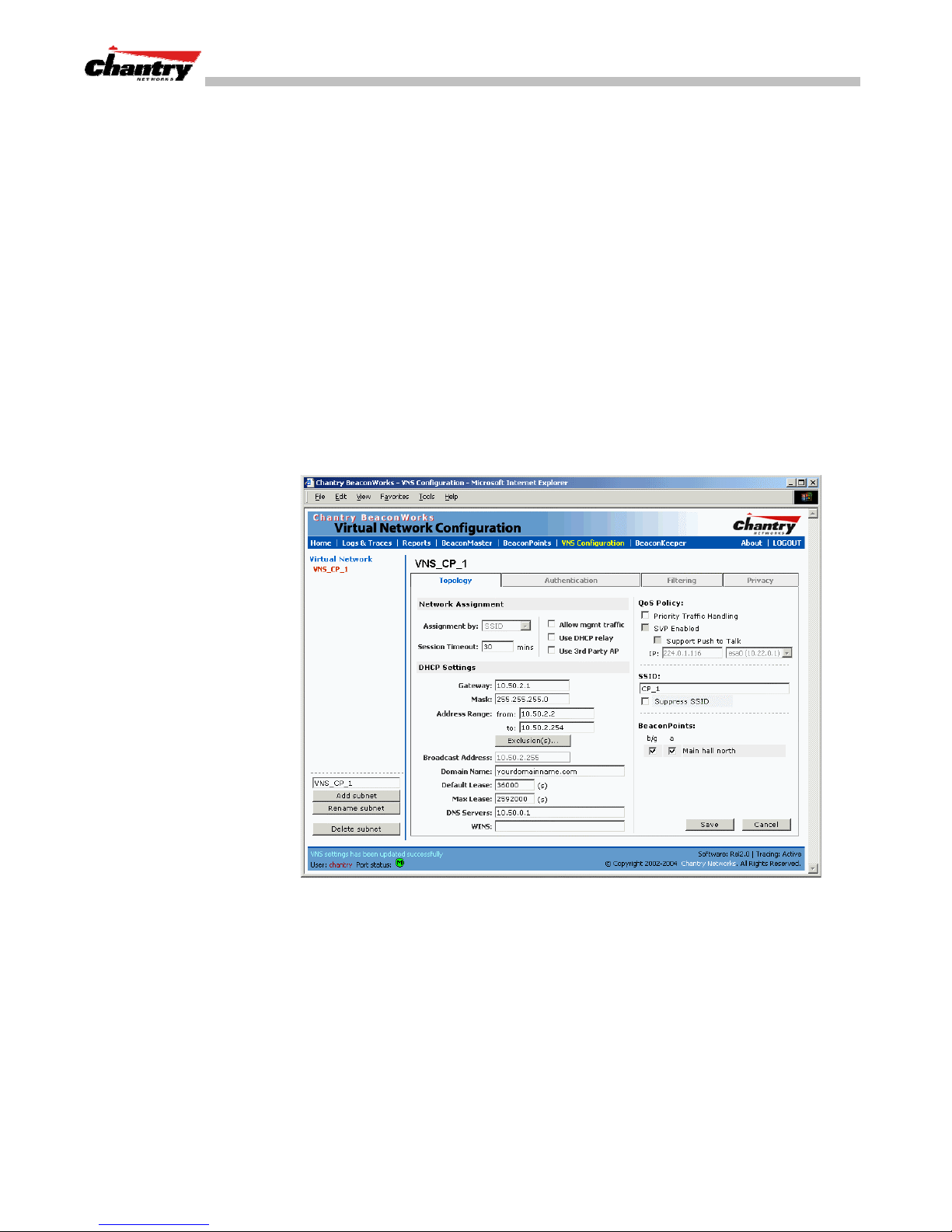
BeaconWorks User Guide – Virtual Network Configuration: A VNS for Captive Portal
Virtual Network Configuration: A VNS for Captive Portal
This section describes how to set up a VNS for Captive Portal: its Topology,
Authentication, Filtering and Privacy.
If the authentication technique for network assignment is by Captive Portal, the
process is as follows. The wireless device requesting network access via
BeaconWorks first gets its IP network assignment from the DHCP server, but can
access only the specific IP addresses defined in the
Typically, one of these addresses is a
device user can log in and become authenticated.
Topology for a VNS for Captive Portal
For a VNS with Captive Portal authentication, select Network Assignment by SSID in
Topology
the
In the
list and click on the
screen.
Virtual Network Configuration
Topology
Captive Portal web page
screen, highlight the VNS name in the left-hand
tab.
Non-Authenticated Filter
.
, where the wireless
Create an SSID for Captive Portal VNS
1. Using the
2. In the
access the BeaconPoint.
3. Click the
beacon message sent by the BeaconPoint. The wireless device user seeking
network access will not see this SSID as an available choice, and will need to
specify it.
Chantry Networks Inc. Copyright 2004. All rights reserved. BeaconWorks Rel 2.0 (051304) Page 50 of 134
Screen 23: Virtual Network Configuration – Topology – SSID Assignment
Assignment by
SSID
box at the right, key in the SSID that the wireless devices will use to
Suppress SSID
drop-down list, select
checkbox on to prevent this SSID from appearing in the
SSID
.
Page 51

BeaconWorks User Guide – Virtual Network Configuration: A VNS for Captive Portal
4. In the
Session Timeout
box, key in the number of minutes that a wireless device
can be inactive before the BeaconMaster closes the session.
Identify the BeaconPoint radios that will be assigned to this VNS
5. From the displayed list of
BeaconPoint Radios
that are available throughout the
network, check the ones to be assigned to this VNS.
Once you have assigned a BeaconPoint radio to four VNSs, it will not appear in
the list for another VNS setup.
Note:
You can view the VNSs that each radio is participating in by clicking on the
appropriate tab for each radio in the
Enable Management Traffic on this VNS
6. To allow Management Traffic on this VNS, click the
BeaconPoint Configuration
Allow management traffic
screen
checkbox on.
Note:
This choice invokes the built-in port-based filtering rules for Management
Traffic, as described earlier in the “Port Type or Function” topic.
Enable Third Party Access Points on this VNS
7. If this VNS is to be used for third-party access points, click the
Use 3rd Party AP
checkbox on. The screen changes to include fields to enter the IP Address and
MAC Address of the third-party access point.
Note:
Use this function as part of the process defined in the topic “Setting up a Third-
Party Access Point”. For further information, see that section in this Guide.
Enable QoS Policy for voice-over-internet traffic on this VNS
8. To set up this VNS to prioritize voice-over-internet traffic, click on the
Traffic Handling
Note:
There is no authentication on a voice traffic VNS. For more information about a
checkbox. Enable
SVP
by clicking on the checkbox.
Priority
voice traffic VNS, see the “Quality of Service (QoS) on a VNS” in this Guide.
Set the IP address for the VNS (for the DHCP server on the BeaconMaster)
9. In the
Network Address
This IP address is the
box, key in the network IP address for the VNS.
default gateway
for the VNS. The BeaconMaster advertises
this address to the wireless devices when they sign on.
Mask
10. In the
box, key in the appropriate subnet mask for this IP address, to
separate the network portion from the host portion of the address (typically
255.255.255.0)
Address Ranges
The
fields populate automatically (based on the IP address you
keyed in) with the range of IP addresses to be assigned to wireless devices using
this VNS.
11. To modify the
Key the last available address in the
12. If there are specific IP addresses to be excluded from this range, click on the
Exclusions
Chantry Networks Inc. Copyright 2004. All rights reserved. BeaconWorks Rel 2.0 (051304) Page 51 of 134
Address Ranges,
field. The
Exclusions
key the first available address in the
to
box.
subscreen appears.
from
box.
Page 52
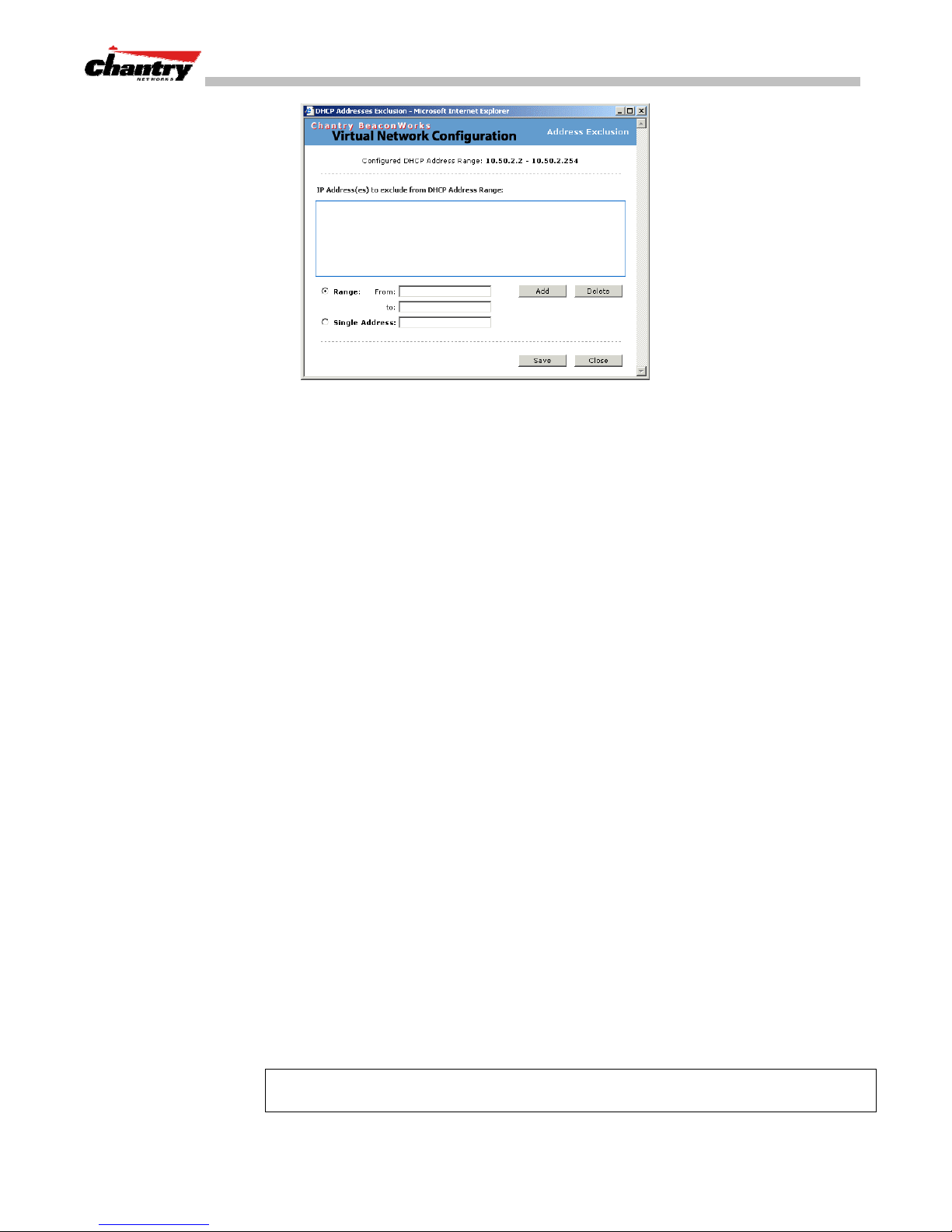
BeaconWorks User Guide – Virtual Network Configuration: A VNS for Captive Portal
Screen 24: Virtual Network Configuration – Exclusions subscreen
13. In the
14. The
Exclusions
Click on the
subscreen, key in the IP addresses or address ranges to exclude.
Add
button after each entry. Click on the
changes and return to the
Broadcast Address
Save
button to save the
Topology
screen.
field populates automatically, based on the IP address
and subnet mask of the VNS. Modify this if appropriate..
15. In the
Set time limits for IP assignments
16. In the
Domain Name
Default Lease
box, key in the external enterprise domain name.
box, accept the default value of 3600 seconds (1 hour), or
modify. This is the default time limit that an IP address would be assigned by the
DHCP server to a wireless device.
In the
Max Lease
box, accept the default value is 24000 seconds (40 hours), or
modify. This is the maximum time that an IP address can be assigned.
Set the name server configuration
17. In the
DNS Servers
box, key in the IP Address of the Domain Name Server(s) to
be used.
18. If the DHCP server uses WINS (Windows Internet Naming Service), key in the IP
WINS
address in the
Use DHCP Relay for the VNS
box. If not, leave it blank.
DHCP Relay
Use
DHCP server on the enterprise network. This function will bypass the local DHCP
server on BeaconMaster (to bypass steps 9 to 18 above). This function allows the
enterprise to manage IP address allocation to a VNS from its existing infrastructure.
19. To use an external DHCP server, click the
DHCP Settings
and
the enterprise’s external DHCP server.
Note:
The range of IP addresses to be assigned to the wireless device users on this
VNS should also be designated on the external DHCP server.
Chantry Networks Inc. Copyright 2004. All rights reserved. BeaconWorks Rel 2.0 (051304) Page 52 of 134
to force the BeaconMaster to forward DHCP requests to an external
area of the screen changes to display only the
DHCP Server
Use DHCP Relay
checkbox on. The
Gateway IP, Mask
fields. Key in the appropriate IP addresses and mask to reach
Page 53
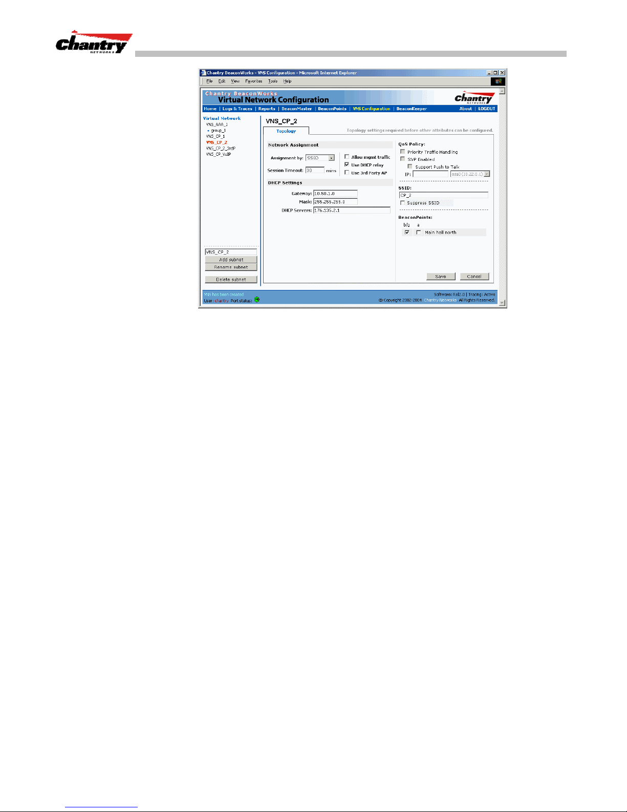
BeaconWorks User Guide – Virtual Network Configuration: A VNS for Captive Portal
Screen 25: Virtual Network Configuration – Topology – DHCP Relay
Save the new VNS
20. To save this VNS configuration, click on the
When the new Topology has been saved, the screen changes to display tabs for
Authentication, Filtering
and
Privacy
Authentication for a VNS for Captive Portal
The next step is to set up the Authentication mechanism for Captive Portal.
For Captive Portal, the wireless device connects to the network, but can only access
the specific network destinations defined in the Non-Authenticated Filter (see
Filtering
Portal). The user must input an ID and a Password. This request for authentication is
sent by the BeaconMaster to a RADIUS server.
Captive Portal authentication relies on a RADIUS server on the enterprise network.
You can define more than one RADIUS server for authentication and define the
priority of use in the event of a failover situation.
Set up authentication by Captive Portal
1. Highlight the VNS name. Click on the
). One of these destinations should be a web page logon screen (the Captive
configuration screen, click the
portion of the screen appears.
.
Authentication
Captive Portal
Save
button.
tab. In the
Authentication
radio button. The Captive Portal
Chantry Networks Inc. Copyright 2004. All rights reserved. BeaconWorks Rel 2.0 (051304) Page 53 of 134
Page 54
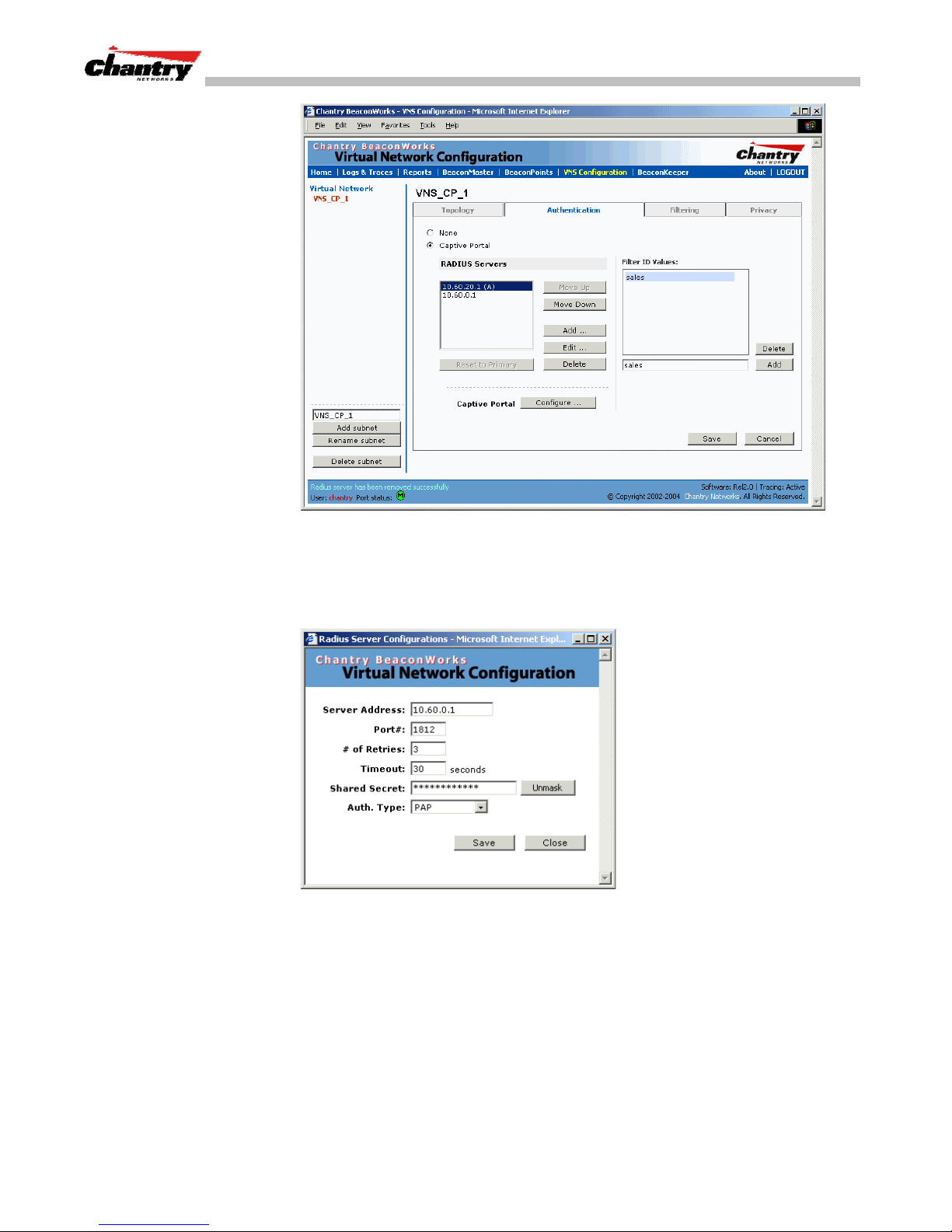
BeaconWorks User Guide – Virtual Network Configuration: A VNS for Captive Portal
Screen 26: Virtual Network Configuration – Authentication – Captive Portal
Define how the BeaconMaster will access the RADIUS server.
2. For each RADIUS server to be defined, click on the
Server Configuration
Screen 27: Virtual Network Configuration – Authentication CP – Add RADIUS Server
popup window appears.
Add
button. The
RADIUS
3. For each server, fill in the following fields:
Server Address
The IP address of the RADIUS server.
Port #
# of Retries
Timeout
Chantry Networks Inc. Copyright 2004. All rights reserved. BeaconWorks Rel 2.0 (051304) Page 54 of 134
The port used to access the RADIUS server (default: 1812)
Number of times the BeaconMaster will attempt to access
the RADIUS server
The maximum time that a BeaconMaster will wait for a
response from the RADIUS server, before attempting again
(up to the maximum number of retries).
Page 55

BeaconWorks User Guide – Virtual Network Configuration: A VNS for Captive Portal
4. Key in the
Shared Secret
(a password that is required in both directions) that is
set up on the RADIUS Server. This password is used to validate the connection
between the BeaconMaster and the RADIUS Server.
To display the shared secret (in order to proofread your entry before saving the
configuration), click on the
Unmask
click on the button again (the button toggles between
Note:
This precautionary step is recommended at this point in order to avoid an error
button. To mask the shared secret again,
Mask
and
Unmask
).
later when the BeaconMaster attempts to communicate with the RADIUS server.
5. Select the authentication protocol to be used by the RADIUS server to
authenticate the users of the wireless devices (for Captive Portal authentication).
PAP
(Password Authentication Protocol)
CHAP
(Challenge Handshake Authentication Protocol)
MS CHAP
MS CHAP v2
6. To save these settings and return to the main
Save
button.
To return to the main
(Windows-specific version of CHAP)
(Windows-specific version of CHAP, version 2)
Authentication
Authentication
screen without saving, click on the
screen, click on the
Close
button.
Define the RADIUS server priority for RADIUS Redundancy
After setting up a RADIUS server, its IP address will appear in the
RADIUS Servers
box. To allow for RADIUS server redundancy, set up one or two additional server, as
described above (three is the maximum).
7. To define the priority of the servers, highlight a RADIUS server in the list and use
Move Up
the
Move Down
or
key to change the order.
The first server in the list is the active one.
In the event of a failover of the main RADIUS server (if no response after the set
number of retries), then the other servers in the list will be polled on a round-robin
basis until one responds.
If one of the other servers becomes the active one during a failover, an “A” will
appear after that server name.
Note:
If all defined RADIUS servers fail to respond, a critical message will be
generated in the logs.
8. To remove a defined server from the list, highlight it and click on the
Delete
button.
9. To modify the parameters of a defined server, highlight it and click on the
Edit
button. In the RADIUS Server popup screen, follow steps 2 to 6 described above.
Note:
It is recommended that the RADIUS databases with names, logins, and
attributes be kept synchronous on all RADIUS servers.
Chantry Networks Inc. Copyright 2004. All rights reserved. BeaconWorks Rel 2.0 (051304) Page 55 of 134
Page 56
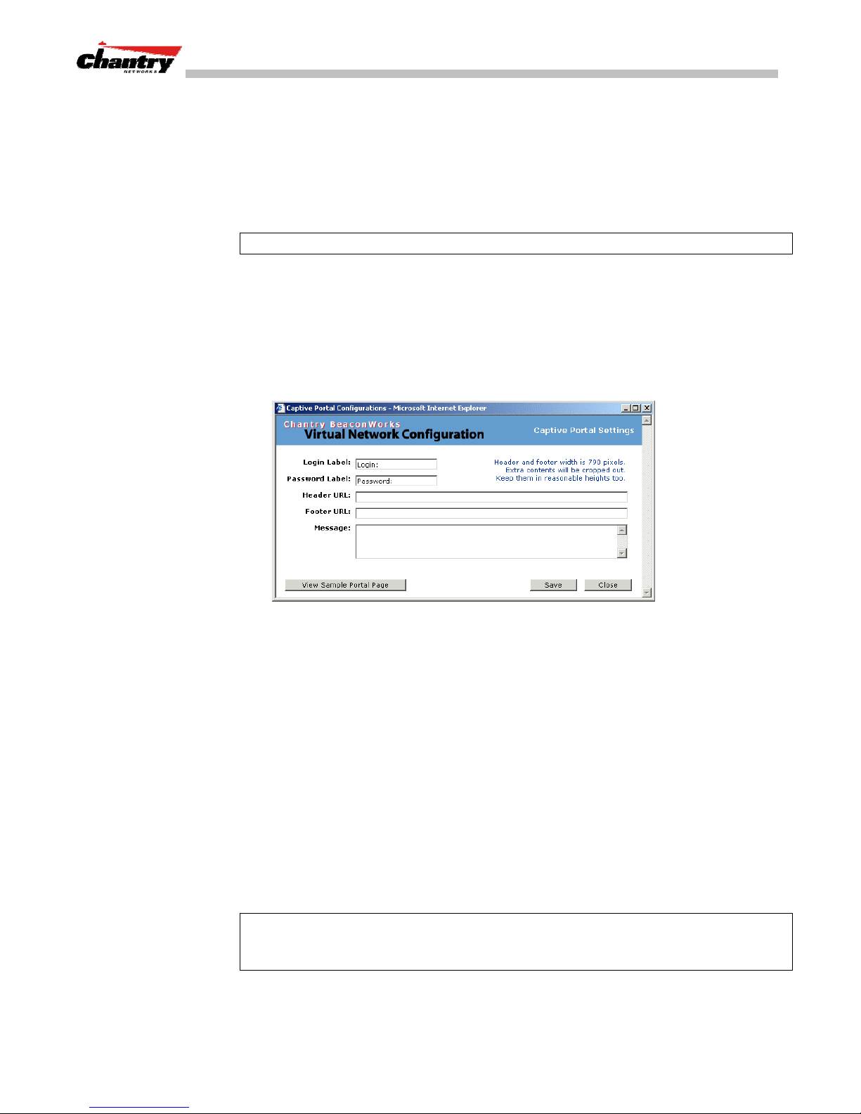
BeaconWorks User Guide – Virtual Network Configuration: A VNS for Captive Portal
Define the Filter ID Values on this VNS.
10. In the
Filter ID Values
entry field, key in the name of a group that you want to
define specific filtering rules for, to control network access. Click on the
Add
button. The Filter ID name appears in the list above.
Repeat for additional Filter ID names.
These Filter ID names will appear in the Filter ID list in the
Note
: These names must match the Filter ID attribute names in the RADIUS server.
11. To save the authentication parameters for this VNS, click on the
Configure the appearance of the Captive Portal page
Filtering
screen.
Save
button.
1. To design how the Captive Portal authentication page will display for Captive
Portal, click on the
Portal Configuration
Configure
button in the
subscreen appears.
Authentication
screen. The
Captive
Screen 28: Captive Portal login configuration
2. Key in the text that will appear on the Captive Portal page.
Login Label
The text that will appear as a label for the user login field in
the Captive Portal screen.
Password Label
The text that will appear as a label for the user password
field
3. Key in the locations of the header and footers.
Header URL
The location of the file to be displayed in the Header portion
of the Captive Portal screen. This page can be customized to
suit your company, with logos or other graphics. (Caution:
Ensure that such graphics in the header are not so large that
they push the login area out of view.)
Footer URL
The location of the file to be displayed in the Footer portion
of the Captive Portal screen.
Note:
You can also add URLs in the header and footer that link to other websites, to
allow the wireless device user to access to some specific areas of your enterprise, or to
the World Wide Web, before authentication.
Chantry Networks Inc. Copyright 2004. All rights reserved. BeaconWorks Rel 2.0 (051304) Page 56 of 134
Page 57

BeaconWorks User Guide – Virtual Network Configuration: A VNS for Captive Portal
4. In the
Message
field, key in the message that will appear above the login field to
greet the user. For example, this could explain why this Captive Portal page is
appearing, and what the user should do.
5. To save this configuration, click on
6. To see how the Captive Portal page you have designed will look (after saving the
configuration), click on the
View Sample Portal Page
Filtering Rules for a VNS for Captive Portal
The next step is to configure the filtering rules for a Captive Portal VNS. Three types
of filters are required:
• Non-Authenticated Filter, with restrictive filtering rules that apply to all wireless
device users
• Filter ID filtering rules that apply
returns the “access-accept” message along with associated Filter ID for the user.
• Default filtering rules that apply
there are no Filter ID matches for the user.
The Non-Authenticated Filter
The Non-Authenticated Filter should allow access to the Captive Portal page IP
address, as well as to any URLs for the header and footer of the Captive Portal page.
The filter should also allow network access to the IP address of the DNS server and to
the Network Address, the Gateway, of the VNS (the VNS Gateway is used as the IP
for the Captive Portal page).
before authentication
Save
.
.
after authentication
after authentication
button.
, when the RADIUS server
, to control network access if
You can also set up filtering rules to allow access, before authentication, to explicitly
defined areas of the network. Then you must deny all other access.
Redirection and captive portal credentials only apply to HTML traffic, that is, if a
wireless device user is attempting to reach websites other than those specifically
allowed in the Non-Authenticated Filter, they will be redirected to the allowed
destinations.
All other network access will be controlled after the user is authenticated, when the
Filter ID or Default filtering rules are applied. The wireless device user who does not
authenticate will not get a wireless session.
Define filtering rules for a Non-Authenticated Filter
1. In the
Filtering
Virtual Network Configuration
screen, click on the
screen appears. Click on the subnet name in the left-hand list. The right
Filtering
tab. The
portion of the screen displays the filtering screen for the selected subnet.
2. Using the
Note:
If you defined specific Filter ID Values in the
Filter ID
Filter IDs will appear in
drop-down list, select
Filter ID
drop-down list.
Non-Authenticated
Authentication
.
screen, these
Chantry Networks Inc. Copyright 2004. All rights reserved. BeaconWorks Rel 2.0 (051304) Page 57 of 134
Page 58
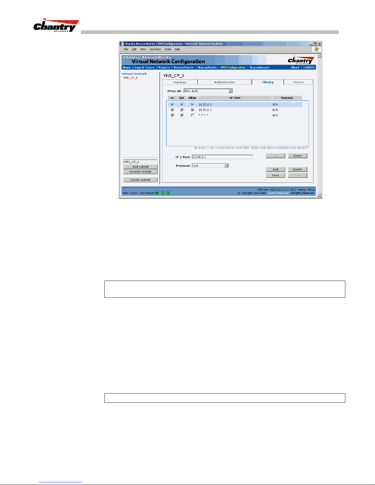
BeaconWorks User Guide – Virtual Network Configuration: A VNS for Captive Portal
Screen 29: Virtual Network Configuration – Non-Authenticated Filter for Captive Portal
Filtering
The
screen automatically provides a “Deny All” rule already in place.
Use this rule as the final rule in the Non-Authenticated Filter for Captive Portal.
3. For each filtering rule you are defining:
IP / Port:
Type in the destination IP address. You can also specify an IP
range, a port designation or a port range on that IP address.
Protocol:
Default is N/A. To specify a protocol, select from the drop-down
list (may include UDP, TCP, IPsec-ESP, IPsec-AH, ICMP).
Note
: For Captive Portal, select
Network Address in the
4. Click on the
Add
Topology
button.
The information appears in a new line in the
IP / Port
and key in the IP address you defined as the
screen for this VNS (its default gateway)
Filter Rules
area of the screen.
5. Highlight the new filtering rule and fill in (or leave unchecked) the three
checkboxes in the combinations that define the traffic access:
In:
Click checkbox on to refer to traffic from the wireless device that
is trying to get on the network (“going to” the network)
Out:
Click checkbox on to refer to traffic from the network host that is
trying to get to a wireless device. (“coming from” the network)
Allow
Note
: For Captive Portal, to allow access to the IP address, check all three boxes on.
6. Edit the order of a filtering rule by highlighting the line and clicking on the
and
7. To save the filtering rules, click on the
Chantry Networks Inc. Copyright 2004. All rights reserved. BeaconWorks Rel 2.0 (051304) Page 58 of 134
Click checkbox on to
Down
button. The filtering rules are executed in the order defined here.
allow
. Leave unchecked to
Save
button.
disallow
.
Up
Page 59

BeaconWorks User Guide – Virtual Network Configuration: A VNS for Captive Portal
Non-Authenticated Filters: Examples
A basic Non-Authenticated Filter for Captive Portal should have three rules in the
following order:
In Out Allow IP / Port Description
x x x IP address of the Default
Gateway
xx x
x x *.*.*.* Deny everything else.
IP address of the DNS
Server
Note:
If you put URLs in the header and footer of the Captive Portal page, you must
Allow all incoming wireless devices access to the default gateway of
the VNS.
Allow all incoming wireless devices access to the DNS server of the
VNS.
include a filtering rule to allow traffic to each of these URLs. Put this rule above the
“deny everything” rule.
Here is another example of a Non-Authenticated Filter that adds two more filtering
rules: one denies access to a specific IP address, and the next rule allows only HTML
traffic, before denying all other access:
In Out Allow IP / Port Description
x x x IP address of the Default
Gateway
xx x
x x [a specific IP address, or
x x x *.*.*.*:80 Allow all port 80 (HTML) traffic.
x x *.*.*.*. Deny everything else.
IP address of the DNS
Server
address plus range]
Allow all incoming wireless devices access to the default gateway of
the VNS.
Allow all incoming wireless devices access to the DNS server of the
VNS.
Deny all traffic to a specific IP address,
or to a specific range within an IP address (such as :0/24)
Once a wireless device user has logged in on the Captive Portal page, and has been
authenticated by the RADIUS server, then the following filters will apply:
• Filter ID Filter, if a Filter ID associated with this user was returned the
authentication server
• Default Filter, if no matching Filter ID was returned from the authentication server.
These filters are described in detail in the
Privacy using WEP for a VNS for Captive Portal
Use the
selected VNS, so that it matches the WEP mechanism used on the rest of the network.
In BeaconWorks Release 2.0, you can assign each radio on a BeaconPoint to up to
four VNSs by SSID. For each VNS, only one WEP key can be specified.
BeaconWorks always uses the first key (key index 0).
Set up a Static WEP key for a selected VNS
1. In the
Privacy
screen to set up the static Wired Equivalent Privacy (WEP) keys for a
Virtual Network Configuration
Privacy
screen appears.
Filtering for an AAA VNS
screen, click on the
Privacy
.
tab. The
Chantry Networks Inc. Copyright 2004. All rights reserved. BeaconWorks Rel 2.0 (051304) Page 59 of 134
Page 60
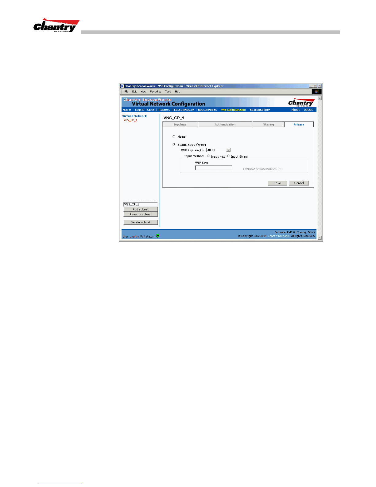
BeaconWorks User Guide – Virtual Network Configuration: A VNS for Captive Portal
2. Click on the VNS subnet name in the left-hand list. The right portion of the screen
displays the privacy parameters for the selected subnet.
None
3. For no privacy mechanism on this VNS, click on the
radio button.
4. To configure static keys for WEP, click on the
Screen 30: Virtual Network Configuration – Privacy – Captive Portal VNS
Static Keys (WEP)
radio button.
5. From the drop-down list, select the
6. Click on the appropriate radio button to select the
WEP Key Length:
Input Method
40-bit, 104-bit, 128-bit
:
Input Hex, Input String.
7. Type in the WEP key input, as appropriate to the technique selected. The key is
generated automatically, based on the input.
Save
8. To save these settings, click on the
button.
Chantry Networks Inc. Copyright 2004. All rights reserved. BeaconWorks Rel 2.0 (051304) Page 60 of 134
Page 61
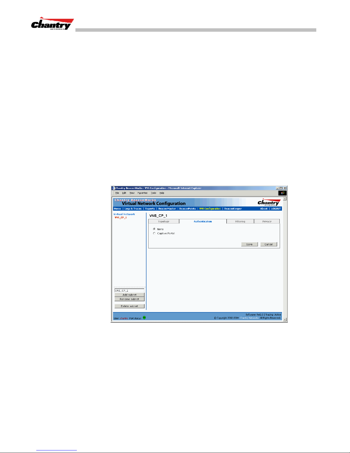
BeaconWorks User Guide – Virtual Network Configuration: A VNS with No Authentication
Virtual Network Configuration: A VNS with No Authentication
You can choose to set up a VNS that will bypass all Chantry authentication
mechanisms and run BeaconWorks with no authentication of a wireless device user.
On such a VNS, however, you can still control network access with filtering rules. See
Filtering Rules: Non-Authenticated Filter for Captive Portal
the
on how to set up filtering rules that allow access only to specified IP addresses and
ports.
Set up a VNS with no authentication
topic for information
1. In the
2. In the
Virtual Network Configuration
hand list and click on the
Topology
screen, select Network Assignment by
Topology
screen, highlight the VNS name in the left-
tab.
SSID
.
For the remaining Topology parameters, follow the steps described above for a
VNS for Captive Portal.
Save
Save the new VNS Topology by clicking on the
3. Then click on the
Authentication
tab for this VNS.
button..
4. Select the
Save
5. In the
network access for any wireless device users on this VNS. These rules should be
very restrictive. The final rule should be a “Deny All” rule.
See “Filtering Rules for a VNS for Captive Portal” for more information.
The Non-Authenticated Filter for a VNS with no authentication will not have a
Captive Portal page for login.
Chantry Networks Inc. Copyright 2004. All rights reserved. BeaconWorks Rel 2.0 (051304) Page 61 of 134
Screen 31: Virtual Network Configuration – Authentication – None
None
radio button, for no authentication on this VNS. Click on the
button.
Filtering
screen, define a Non-Authenticated Filter that will control specific
Page 62

BeaconWorks User Guide – Virtual Network Configuration: A VNS for Voice Traffic (QoS with
Virtual Network Configuration: A VNS for Voice Traffic (QoS with SVP)
Voice Data Traffic on a Wireless Network: Overview
New developments are enabling the integration of internet telephony technology on
wireless networks – Voice over Internet Protocol (VoIP) using 802.11 wireless local
area networks (WLANs).
VoIP over 802.11 WLANs raises various issues including quality-of-service (QoS),
call control, network capacity, and network architecture.
Wireless voice data requires a constant transmission rate and must be delivered within
a time limit. This type of data is called
isochronous data is in contradiction to the concepts in the 802.11 standard that allow
for data packets to wait their turn, to avoid data collisions. (Regular traffic on a
wireless network is an
asynchronous
random intervals.)
The solution is to add mechanisms to the network that give voice data traffic priority
over all other traffic, and allow for continuous transmission of voice traffic.
isochronous
data. This requirement for
process in which data streams are broken up by
SVP)
One such mechanism is SpectraLink Voice Protocol (SVP), a protocol developed by
SpectraLink for implementation on an access point. The SVP protocol facilitates voice
prioritization over an 802.11 wireless LAN that will carry voice packets from
SpectraLink wireless telephones.
In BeaconWorks Release 2.0, you can configure a VNS that supports wireless voiceover-internet devices. Specifically, you can enable SpectraLink Voice Protocol (SVP)
on the VNS in order to provide priority queuing on the BeaconPoint.
This feature is part of the development of Quality of Service (QoS) mechanisms in
BeaconWorks. Such techniques match the needs of specific applications to the
network resources available, in order to provide better network traffic flow.
Setting up a VNS for Voice Traffic
In order to set up a VNS for voice-over-internet traffic, a number of factors should be
taken into account, on the enterprise network and in the BeaconWorks system.
On the enterprise network, the wireless telephone users will require access to:
• a private branch exchange (PBX), a private telephone system within an enterprise,
with such features as voicemail.
• a Telephony Gateway, for access to an external standard telephone network, such
as the wireless cellular network or the public switched telephone network (PSTN).
Note:
The Telephony Gateway should be located on the same subnet as the
BeaconMaster.
For large deployments, an SVP server is required on the enterprise network.
Chantry Networks Inc. Copyright 2004. All rights reserved. BeaconWorks Rel 2.0 (051304) Page 62 of 134
Page 63
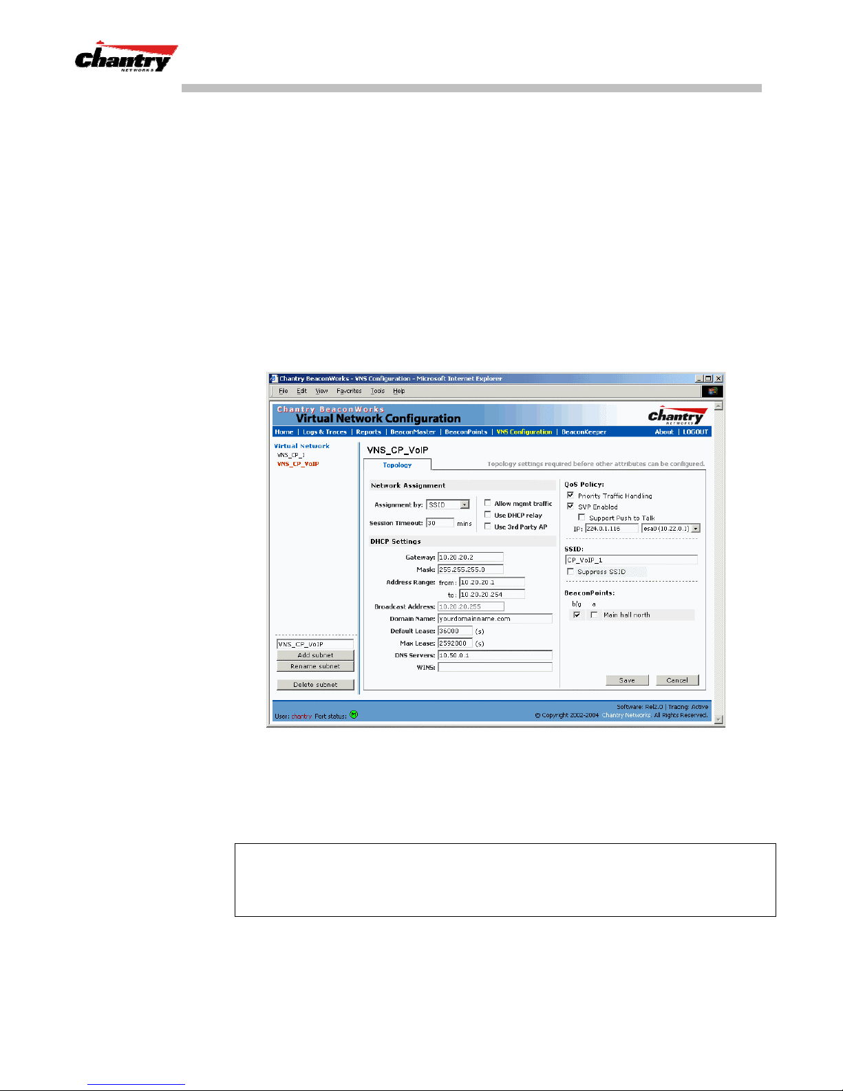
BeaconWorks User Guide – Virtual Network Configuration: A VNS for Voice Traffic (QoS with
SVP)
In BeaconWorks, the VNS that is dedicated voice-over-internet traffic should be
configured as follows:
• Network assignment by
• Authentication set to
SSID
None
, since wireless telephone users do not have a user
interface in which they can enter authentication identification
• Filtering rules that allow access to the DNS server, to the Telephony Gateway, and
then deny all other traffic.
• Privacy using 104-bit WEP key (recommended for greater security).
Set up a VNS for voice traffic
1. In the
Virtual Network Configuration
screen, add a new VNS, as described earlier.
Then configure the VNS as described below.
Screen 32: Virtual Network Configuration: Topology – QoS for Voice Traffic
2. In the
down list.
3. In the
the checkbox on.
Note:
It is possible to enable only the Priority Traffic Handling on a VNS without
using SVP. The Priority Traffic Handling mode sets the BeaconPoint to give priority
to traffic on this VNS. There is no multicast on with this feature.
However, this mode is usually used together with SVP enabled (the next feature)
4. To enable SVP on the VNS, click the
When SVP is enabled, multicast traffic is also automatically enabled.
Chantry Networks Inc. Copyright 2004. All rights reserved. BeaconWorks Rel 2.0 (051304) Page 63 of 134
Topology
QoS Policy
screen, in the
Assignment by
area of the screen, enable
SVP Enabled
field, select
Priority Traffic Handling
SSID
from the drop-
checkbox on.
by clicking
Page 64
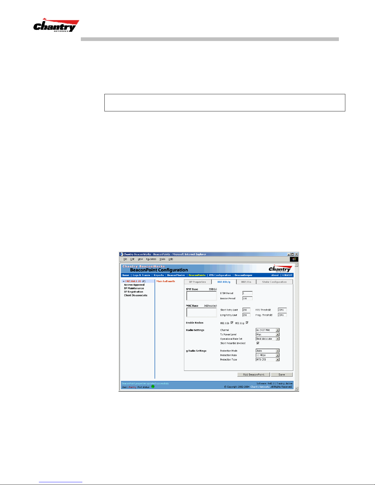
BeaconWorks User Guide – Virtual Network Configuration: A VNS for Voice Traffic (QoS with
SVP)
5. Define parameters for multicast. The IP entry field displays an IP address that
SVP can use for multicast. The next field displays one of the BeaconMaster
physical data ports for multicast. You can modify these if required.
6. To allow this VNS to handle Push-To-Talk wireless communication, click the
Support Push-To-Talk
Note:
The Push-To-Talk feature on wireless telephones allows direct communication
checkbox on.
between any devices open on the same handset channel (like a walkie-talkie).
7. Define the remaining parameters of the VNS topology as described earlier for
network assignment by SSID.
Save
8. To save this VNS configuration, click on the
button.
9. In the
10. In the
Authentication
Click on the
Filtering
screen, set the Authentication method for this VNS to
Save
button.
screen, define filtering rules in the Non-Authenticated Filter that
allow access to the DNS server, to the Telephony Gateway, and then deny all
Save
other traffic. Click on the
11 In the
Privacy
screen, set up Privacy using a 104-bit WEP key. Click on the
button.
button.
Configure the BeaconPoint radio for a voice traffic VNS
BeaconPoint Configuration
In the
screen, make the following changes on the
BeaconPoint radio for this VNS, to support SVP requirements:
None
Save
.
Screen 33: BeaconPoint Configuration for QoS VNS (need screen with correct settings)
1. Set the 2.4 Ghz radio to support only B mode (G mode not supported)
2. Set the operational radio rate to
3. The save these modifications, click on the
Chantry Networks Inc. Copyright 2004. All rights reserved. BeaconWorks Rel 2.0 (051304) Page 64 of 134
Best data rate
Save
.
button.
Page 65

BeaconWorks User Guide – Virtual Network Configuration: A VNS for AAA
Virtual Network Configuration: A VNS for AAA
This section describes how to set up a VNS for AAA (802.1x): its Topology,
Authentication, Filtering and Privacy.
If network assignment is by
AAA (802.1x)
with 802.1x authentication, the process is
as follows. The wireless device user requesting network access via BeaconWorks
must first be authenticated. The wireless device’s client utility must support 802.1x.
The user’s request for network access along with login identification or user profile
will be forwarded by the BeaconMaster to a RADIUS server. BeaconWorks supports
these authentication types:
• EAP-TLS Extensible Authentication Protocol - Transport Layer Security that relies
on client-side and server-side certificates to perform authentication and can be
used to dynamically generate user-based and session-based WEP keys.
• EAP-TTLS (EAP with Tunneled Transport Layer Security) is an extension of
EAP-TLS to provide certificate-based, mutual authentication of the client and
network through an encrypted tunnel, as well as to generate dynamic, per-user,
per-session WEP keys. Unlike EAP-TLS, EAP-TTLS requires only server-side
certificates.
• PEAP (Protected Extensible Authentication Protocol) is a standard to authenticate
wireless LAN clients without requiring them to have certificates. In PEAP
authentication, first the user authenticates the authentication server, then the
authentication server authenticates the user.
Note:
For 802.1x, the RADIUS server must support RADIUS extensions (RFC2869).
If the RADIUS servers sends an “access-accept” message to the BeaconMaster, the
BeaconMaster’s DHCP server assigns the wireless device its IP address.
The BeaconMaster controls network access by means of the filtering rules defined for
the specific Filter ID associated with the wireless device user, as defined in the
Filtering
screen.
For a VNS with AAA (802.1x), privacy by Wi-Fi Protected Access (WPA) is
available.
Topology for a VNS for AAA
For a VNS with 802.1x authentication, select Network Assignment by AAA
(Authentication, Authorization, Accounting) in the
Virtual Network Configuration
In the
list and click on the
Topology
tab.
Topology
screen.
screen, highlight the VNS name in the left-hand
Chantry Networks Inc. Copyright 2004. All rights reserved. BeaconWorks Rel 2.0 (051304) Page 65 of 134
Page 66
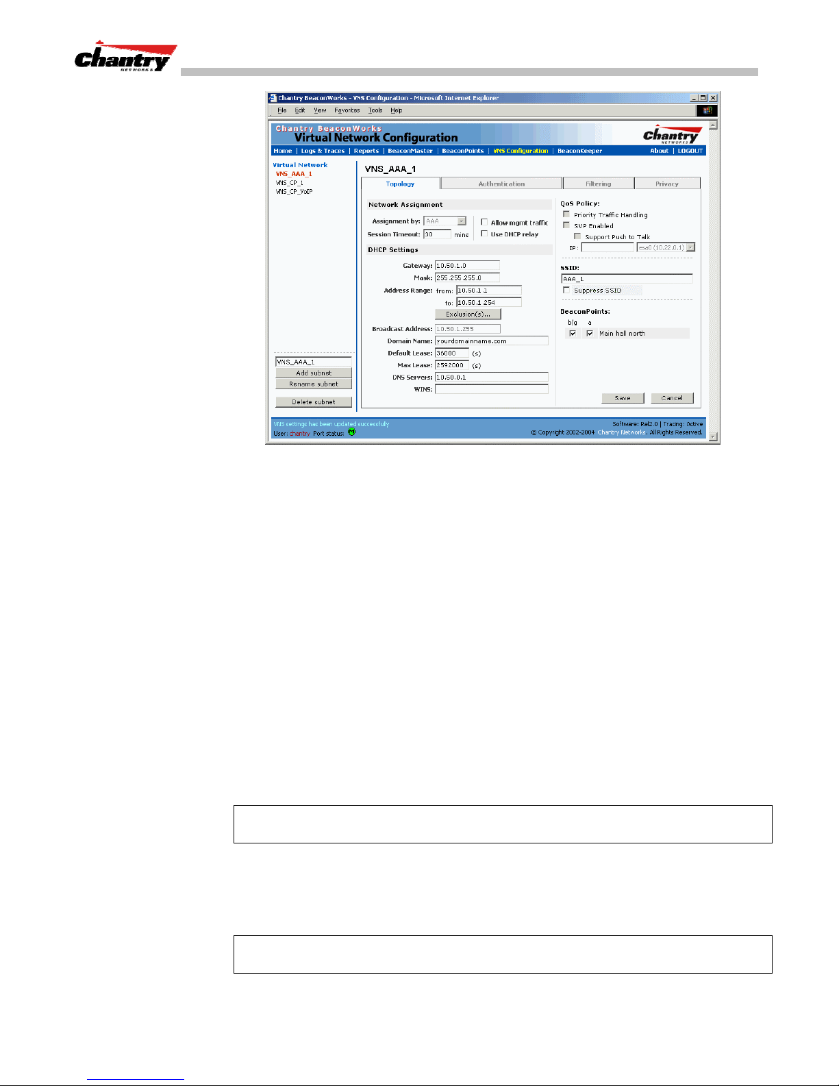
BeaconWorks User Guide – Virtual Network Configuration: A VNS for AAA
Screen 34: Virtual Network Configuration – Topology – AAA Assignment
Create an AAA topology
1. Using the
2. In the
SSID
Assignment by
drop-down list, select
box at the right, key in the SSID that the wireless devices will use to
AAA
.
access the BeaconPoint.
3. Click the
Suppress SSID
checkbox on to prevent this SSID from appearing in the
beacon message sent by the BeaconPoint. The wireless device user seeking
network access will not see this SSID as an available choice, and will need to
specify it.
4. In the
Session Timeout
box, key in the number of minutes that a wireless device
can be inactive before the BeaconMaster closes the session.
Identify the BeaconPoint radios that will be assigned to this VNS
5. From the displayed list of
BeaconPoint Radios
that are available throughout the
network, check the ones to be assigned to this VNS.
Once you have assigned a BeaconPoint radio to four VNSs, it will not appear in
the list for another VNS setup.
Note:
You can view the VNSs that each radio is participating in by clicking on the
appropriate tab for each radio in the
BeaconPoint Configuration
screen
Enable Management Traffic on this VNS
6. To allow Management Traffic on this VNS, click the
checkbox on.
Note:
This choice invokes the built-in port-based filtering rules for Management
Traffic, as described earlier in the “Port Type or Function” topic.
Chantry Networks Inc. Copyright 2004. All rights reserved. BeaconWorks Rel 2.0 (051304) Page 66 of 134
Allow management traffic
Page 67
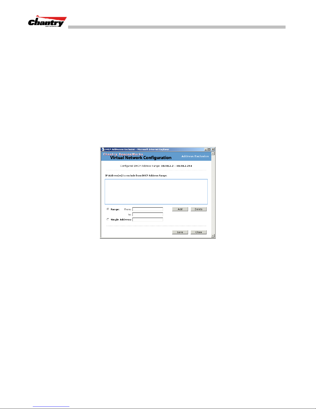
BeaconWorks User Guide – Virtual Network Configuration: A VNS for AAA
Set the IP address for the VNS (for the DHCP server on the BeaconMaster)
7. In the
Network Address
This IP address is the
box, key in the network IP address for the VNS.
default gateway
for the VNS. The BeaconMaster advertises
this address to the wireless devices when they sign on.
Mask
8. In the
box, key in the appropriate subnet mask for this IP address, to
separate the network portion from the host portion of the address (typically
255.255.255.0)
Address Ranges
The
fields populate automatically (based on the IP address you
keyed in) with the range of IP addresses to be assigned to wireless devices using
this VNS.
9. To modify the
Address Ranges,
Key the last available address in the
key the first available address in the
to
box.
from
10. If there are specific IP addresses to be excluded from this range, click on the
Exclusions
field. The
Exclusions
subscreen appears.
box.
Screen 35: Virtual Network Configuration – Exclusions subscreen
11. In the
12. The
Exclusions
Click on the
subscreen, key in the IP addresses or address ranges to exclude.
Add
button after each entry. Click on the
changes and return to the
Broadcast Address
Save
button to save the
Topology
screen.
field populates automatically, based on the IP address of
the VNS. Modify this if appropriate..
13. In the
Set time limits for IP assignments
14. In the
Domain Name
Default Lease
box, key in the external enterprise domain name.
box, accept the default value of 3600 seconds (1 hour), or
modify. This is the default time limit that an IP address would be assigned by the
DHCP server to a wireless device.
In the
Max Lease
box, accept the default value is 24000 seconds (40 hours), or
modify. This is the maximum time that an IP address can be assigned.
Set the name server configuration
15. In the
DNS Servers
box, key in the IP Address of the Domain Name Server(s) to
be used.
Chantry Networks Inc. Copyright 2004. All rights reserved. BeaconWorks Rel 2.0 (051304) Page 67 of 134
Page 68

BeaconWorks User Guide – Virtual Network Configuration: A VNS for AAA
16. If the DHCP server uses WINS (Windows Internet Naming Service), key in the IP
address in the
Use DHCP Relay for the VNS
DHCP Relay
Use
WINS
box. If not, leave it blank.
to force the BeaconMaster to forward DHCP requests to an external
DHCP server on the enterprise network. This function will bypass the local DHCP
server on BeaconMaster (to bypass steps 9 to 18 above). This function allows the
enterprise to manage IP address allocation to a VNS from its existing infrastructure.
17. To use an external DHCP server, click the
DHCP Settings
DHCP Server
and
area of the screen changes to display only the
the enterprise’s external DHCP server.
Note:
The range of IP addresses to be assigned to the wireless device users on this
VNS should also be designated on the external DHCP server.
Save the new VNS for AAA
18. To save this VNS configuration, click on the
When the new Topology has been saved, the screen changes to display tabs for
Authentication, Filtering
Authentication for a VNS for AAA
The next step is to set up the Authentication mechanism for
This type of authentication relies on a RADIUS server on the enterprise network. You
can define more than one RADIUS server for authentication and define the priority of
use in the event of a failover situation.
Set up authentication by AAA (802.1x) method
Use DHCP Relay
checkbox on. The
Gateway IP, Mask
fields. Key in the appropriate IP addresses and mask to reach
Save
button.
Privacy
and
.
AAA (802.1x)
.
1. Highlight the VNS name. Click on the
AAA version of the
Chantry Networks Inc. Copyright 2004. All rights reserved. BeaconWorks Rel 2.0 (051304) Page 68 of 134
Authentication
Authentication
screen appears.
tab. For an AAA VNS, the
Page 69
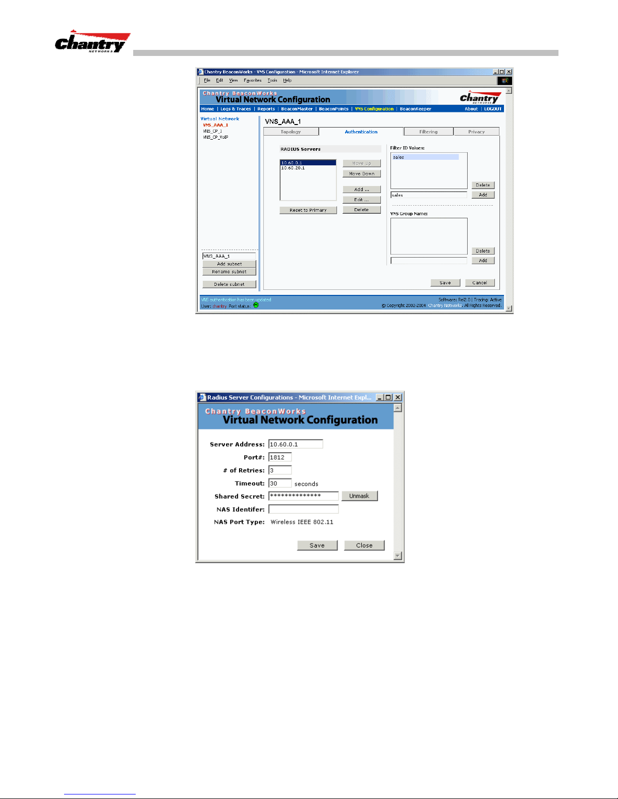
BeaconWorks User Guide – Virtual Network Configuration: A VNS for AAA
Screen 36: Virtual Network Configuration – Authentication – AAA
Define how the BeaconMaster will access the RADIUS Server.
2. For each RADIUS server to be defined, click on the
Server Configuration
Screen 37: Virtual Network Configuration – Authentication AAA – RADIUS Server Configuration
popup window appears.
Add
button. The
RADIUS
3. For each server, fill in the following fields:
Server Address
Port #
The IP address of the RADIUS Server.
The port used to access the RADIUS Server (default: 1812)
# of Retries
Timeout
Chantry Networks Inc. Copyright 2004. All rights reserved. BeaconWorks Rel 2.0 (051304) Page 69 of 134
Number of times the BeaconMaster will attempt to access
the RADIUS Server
The maximum time that a BeaconMaster will wait for a
response from the RADIUS server, before attempting again
(up to the maximum number of retries).
Page 70

BeaconWorks User Guide – Virtual Network Configuration: A VNS for AAA
4. Key in the
Shared Secret
(a password that is required in both directions) that is
set up on the RADIUS Server. This password is used to validate the connection
between the BeaconMaster and the RADIUS Server.
To display the shared secret (in order to proofread your entry before saving the
configuration), click on the
Unmask
click on the button again (the button toggles between
Note:
This precautionary step is recommended at this point in order to avoid an error
button. To mask the shared secret again,
Mask
and
Unmask
).
later when the BeaconMaster attempts to communicate with the RADIUS server.
5. In the
NAS Identifier
field, type in the Network Access Server (NAS) identifier, a
RADIUS attribute that identifies the server responsible for passing information to
designated RADIUS Servers and then acting on the response returned. [Optional]
6. To save these settings and return to the main
Save
button. To return to the main
Close
the
Define the RADIUS server priority for RADIUS Redundancy
button.
Authentication
After setting up a RADIUS server, its IP address appears in the
Authentication
screen, click on the
screen without saving, click on
RADIUS Servers
box.
To allow for RADIUS server redundancy, set up a second server, as described above.
7. To define the priority of the servers, highlight a RADIUS server in the list and use
Move Up
the
Move Down
or
key to change the order.
The first server in the list is the active one.
In the event of a failover of the main RADIUS server (if no response after the set
number of retries), then the other servers in the list will be polled on a round-robin
basis until one responds.
If one of the other servers becomes the active one during a failover, an “A” will
appear after that server name.
Note:
If all defined RADIUS servers fail to respond, a critical message will be
generated in the logs.
8. To remove a defined server from the list, highlight it and click on the
Delete
button.
9. To modify the parameters of a defined server, highlight it and click on the
button. In the RADIUS Server popup screen, follow steps 2 to 6 described above.
Note:
It is recommended that the RADIUS databases with names, logins, and
attributes be kept synchronous on all RADIUS servers.
Define the Filter ID Values on this VNS.
10. In the
Filter ID Values
entry field, key in the name of a group that you want to
define specific filtering rules for, to control network access. Click on the
button. The Filter ID name appears in the list above.
Edit
Add
Repeat for additional Filter ID names.
These Filter ID names will appear in the Filter ID list in the
Chantry Networks Inc. Copyright 2004. All rights reserved. BeaconWorks Rel 2.0 (051304) Page 70 of 134
Filtering
screen.
Page 71
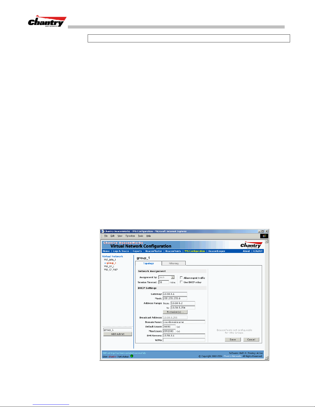
BeaconWorks User Guide – Virtual Network Configuration: A VNS for AAA
Note
: These names must match the Filter ID attribute names in the RADIUS server.
11. To save the authentication parameters for this VNS, click on the
VNS Topology for an AAA group
You can set up a group within a VNS that relies on the RADIUS attribute Login-LATGroup (RFC2865). For each group, you can define filtering rules to control access to
the network.
If you define a group within an AAA VNS, the group (or child) definition acquires the
same authentication and privacy parameters as the parent VNS. However, you need to
define a different topology and filtering rules for this group.
Set up an AAA Group
1. Highlight the VNS name for which you selected
Topology
in the
screen. Click on the
AAA version of the
2. To create and define a VNS Group within the selected parent VNS, key in the
name in the
VNS Group Name
The Group Name that you defined will appear as a child of the parent VNS in the
left-hand list. (To configure the Topology of a group, see the next topic.)
3. To save these settings and create the group VNS definition, click on
Authentication
field. Then click on the
AAA
Authentication
screen appears.
Save
button.
as the Assignment method
tab. For an AAA VNS, the
Add
button.
Save
.
Configure the VNS Topology for an AAA Group
1. To configure the VNS topology for an AAA Group, click on its name in the lefthand list. The Group version of the
Topology
screen appears.
Chantry Networks Inc. Copyright 2004. All rights reserved. BeaconWorks Rel 2.0 (051304) Page 71 of 134
Screen 38: Virtual Network Configuration – Topology – AAA Group
Page 72

BeaconWorks User Guide – Virtual Network Configuration: A VNS for AAA
2. Define the DHCP settings for this VNS, as described above for the parent VNS.
The Gateway and DHCP Ranges must be different than those of the parent VNS.
Save
3. To save the modifications, click on
.
The filtering screen for an AAA Group is described at the end of the
Filtering Rules for a Filter ID group
After setting up RADIUS parameters for Authentication and the Filter ID Values, the
next step is to define the filtering rules for the Filter ID Values on the VNS for AAA.
When the wireless device user enters a login identification, that identification is sent
by the BeaconMaster to the RADIUS server or other authentication server, through a
sequence of exchanges depending on the type of authentication protocol used.
When the server allows this request for authentication (sends an “access-accept”
message), the RADIUS server may also send back to the BeaconMaster a Filter ID
attribute associated with the user, or a Login-LAT-Group identifier for the user.
If the Filter ID attribute (or Login-LAT-Group attribute) from the RADIUS server
matches a Filter ID Value that you have set up on the BeaconMaster, the
BeaconMaster applies to the wireless device user the filtering rules that you defined
for that Filter ID Value.
Note
: The BeaconMaster’s Filter ID Values must match the Filter ID attribute names
in the RADIUS server.
If no Filter ID is returned by the authentication server, or no match is found on the
BeaconMaster, then the Default Filter and its filtering rules will apply to the wireless
device user.
Filtering
topic.
Define filtering rules for a Filter ID group
1. In the
2. Using the
Virtual Network Configuration
and click on the
Filter ID Values
Filtering
Filter ID
field in the
drop-down list, select one of the names you defined in the
tab. The
Filtering
Authentication
screen, highlight the VNS name in the list
screen for this VNS appears.
screen [one of your enterprise’s user
groups, such as Sales, Engineering, Teacher, Guest....]
Chantry Networks Inc. Copyright 2004. All rights reserved. BeaconWorks Rel 2.0 (051304) Page 72 of 134
Page 73
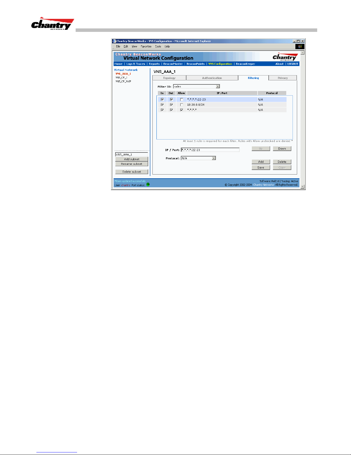
BeaconWorks User Guide – Virtual Network Configuration: A VNS for AAA
Screen 39: Virtual Network Configuration –Filter ID Value filtering rules
The screen automatically provides a “Deny All” rule already in place. This can be
modified to “Allow All”, if appropriate to the network access needs for this VNS.
3. Select one of the following as the basis for each filtering rule you are defining:
IP / Port:
Type in the destination IP address, and if desired, the port
designation on that IP address.
Protocol:
Select from the drop-down list (may include UDP, TCP, IPsecESP, IPsec-AH, ICMP)
Add
4. Click on the
The information appears in a new line in the
button.
Filter Rules
area of the screen.
5. Highlight the new filtering rule and fill in (or leave unchecked) the three
checkboxes in the combinations that define the traffic access:
In:
Click checkbox on to refer to traffic from the wireless device that
is trying to get on the network (“going to” to network)
Out:
Click checkbox on to refer to traffic from the network host that is
trying to get to a wireless device. (“coming from” the network)
Allow
Click checkbox on to
6. Edit the order of a filtering rule by highlighting the line and clicking on the
Down
and
button. The filtering rules are executed in the order defined here
allow
. Leave unchecked to
disallow
..
Up
7. To save the filtering rules, click on the
Filtering Rules by Filter ID: Examples
Below are two examples of possible filtering rules for a Filter ID. The first disallows
only some specific access before allowing everything else.
Chantry Networks Inc. Copyright 2004. All rights reserved. BeaconWorks Rel 2.0 (051304) Page 73 of 134
Save
button.
Page 74
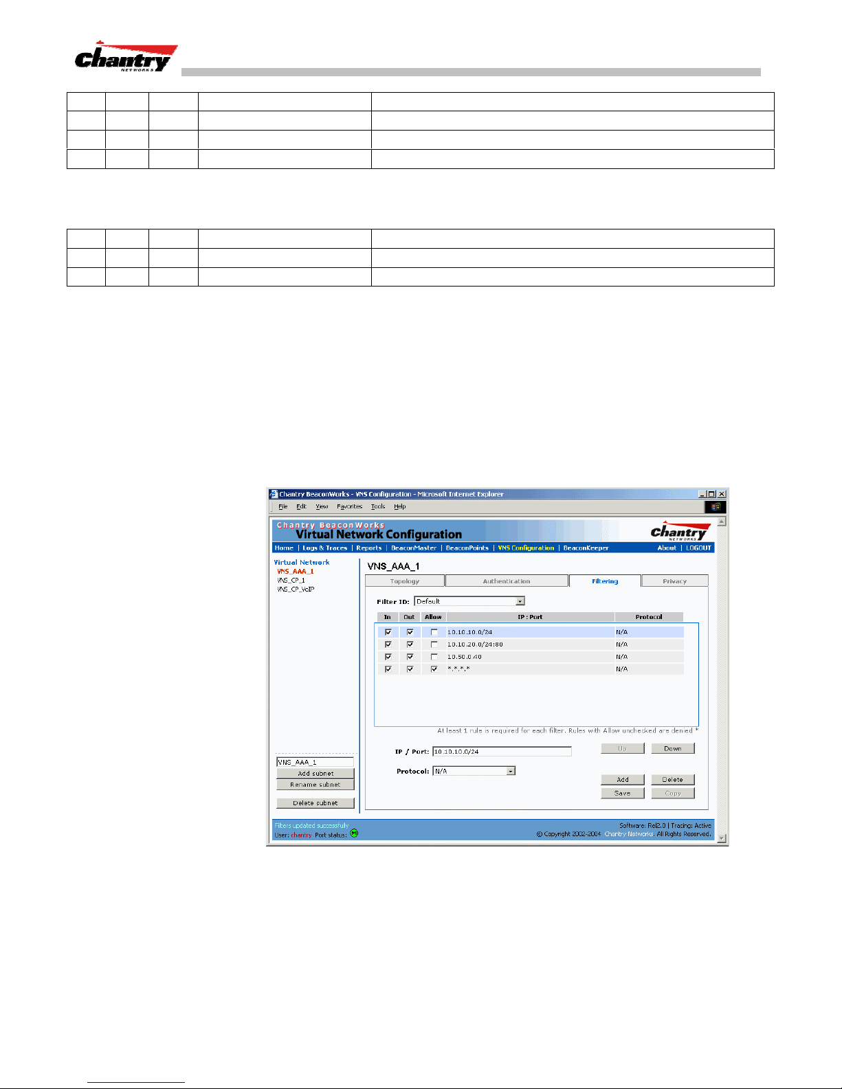
BeaconWorks User Guide – Virtual Network Configuration: A VNS for AAA
In Out Allow IP / Port Description
x x *.*.*.*:22-23 Deny all telnet sessions
x x [specific IP address, range] Deny all traffic to a specific IP address, or address range
x x x *.*.*.*. Allow everything else.
The second example does the opposite of the first example. It allows only some
specific access and denies everything else.
In Out Allow IP / Port Description
x x x [specific IP address, range] Allow all traffic to a specific IP address, or address range
x x *.*.*.*. Deny everything else.
Filtering Rules for a Default Filter
If, after authentication of the wireless device user, no Filter ID attribute is returned by
the authentication server for this user, or no match is found on the BeaconMaster for a
Filter ID Value, then the Default Filter will apply.
Define the filtering rules for a Default Filter
1. In the
Virtual Network Configuration – Filtering
down list, select
Default
screen, using the
Filter ID
drop-
.
2. Follow Steps 2 to 5, as described above.
3. To save the filtering rules, click on the
Default Filter: Examples
Here is an example of filtering rules for a Default Filter:
Chantry Networks Inc. Copyright 2004. All rights reserved. BeaconWorks Rel 2.0 (051304) Page 74 of 134
Screen 40: Virtual Network Configuration – Default Filter
Save
button.
Page 75
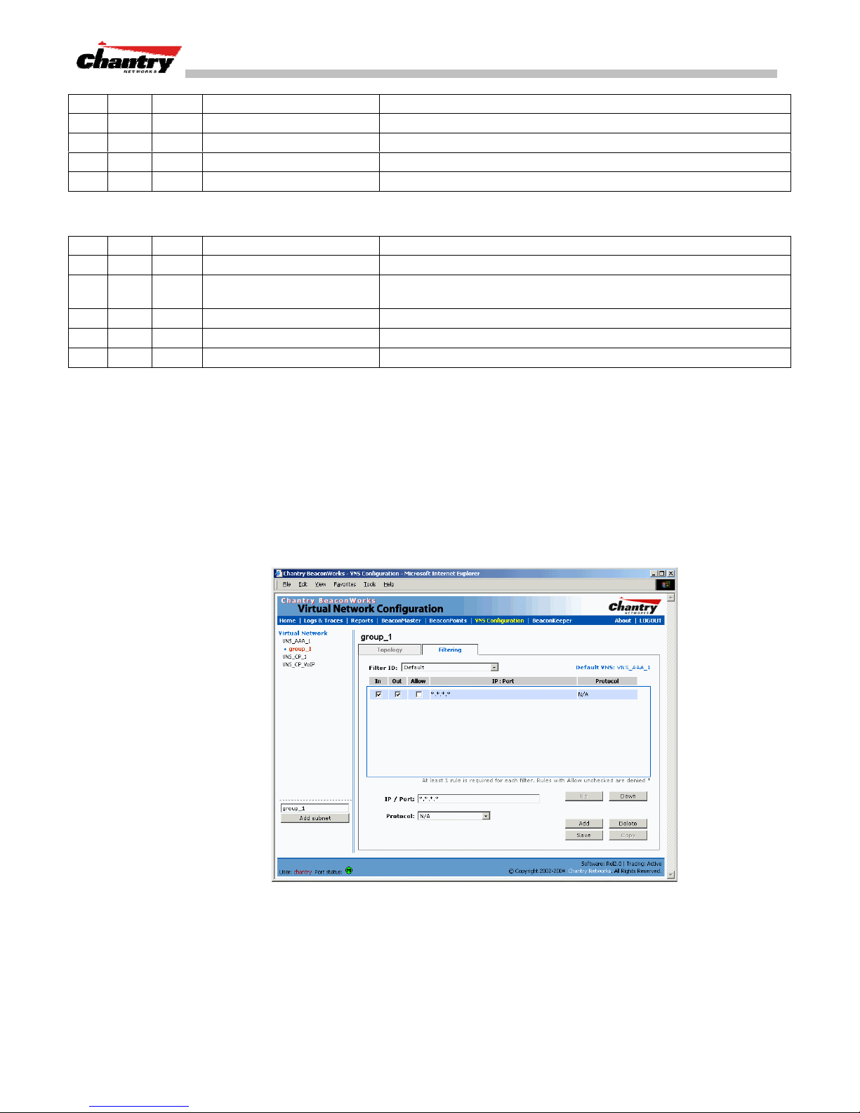
BeaconWorks User Guide – Virtual Network Configuration: A VNS for AAA
In Out Allow IP / Port Description / Purpose
x x Intranet IP, range Deny all access to an IP range
x x Port 80 (HTTP) Deny all access to web browsing.
x x Intranet IP Deny all access to a specific IP
x x x *.*.*.*. Allow everything else.
Here is another example of filtering rules for a Default Filter:
In Out Allow IP / Port Description / Purpose
x Port 80 (HTTP) on host IP Deny all incoming wireless devices access to web browsing the host.
x
x x Intranet IP 10.3.0.20 Allow all other traffic from the wireless devices to the Intranet network.
x x Intranet IP 10.3.0.20 Allow all other traffic from Intranet network to wireless devices.
x x x *.*.*.*. Allow everything else.
Intranet IP 10.3.0.20, ports
10-30
Filtering Rules for an AAA Group VNS
Deny all traffic from the network to the wireless devices on the port
range, such as TELNET (port 23) or FTP (port 21).
If you defined a child group for an AAA VNS, it will have the same authentication
parameters and Filter IDs as the parent VNS. However, you can define different
filtering rules for these Filters IDs in the child configuration than in the parent
configuration.
1. In the
Virtual Network Configuration
list and click on the
Filtering
tab. The
screen, highlight the VNS group name in the
Filtering
screen for this VNS group
appears.
Screen 41: Virtual Network Configuration – Filtering – AAA Group
2. Follow Steps 2 to 5, as described above for a parent VNS.
3. To save the filtering rules, click on the
Chantry Networks Inc. Copyright 2004. All rights reserved. BeaconWorks Rel 2.0 (051304) Page 75 of 134
Save
button.
Page 76
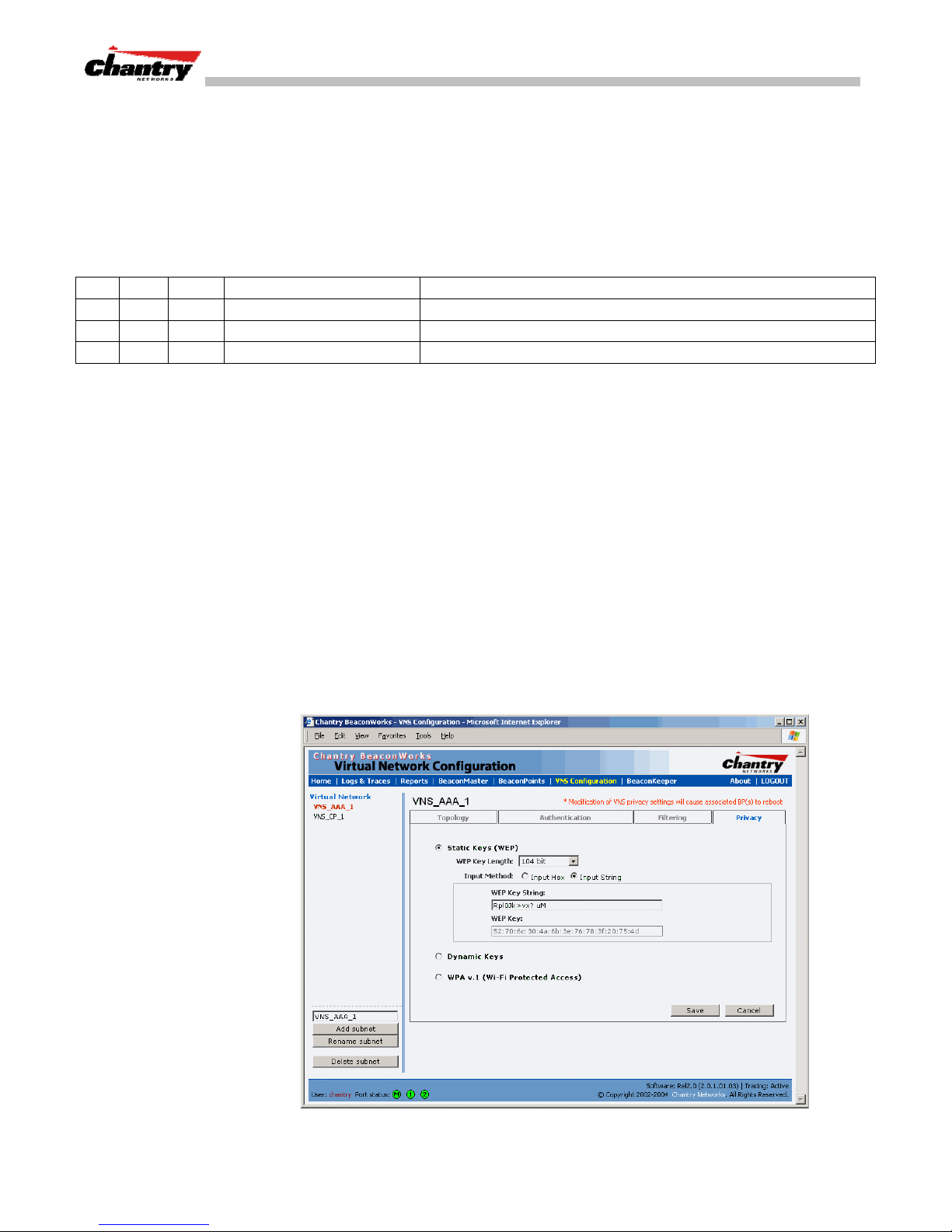
BeaconWorks User Guide – Virtual Network Configuration: A VNS for AAA
Filtering Rules between two wireless devices
Traffic from two wireless devices that are on the same VNS and are connected to the
same BeaconPoint will pass through the BeaconMaster and therefore be subject to
filtering policy.
You can set up filtering rules that allow each wireless device access to the default
gateway, but prevent each device from communicating each other. Add the following
two rules to a Filter ID filter before allowing everything else:
In Out Allow IP / Port Description / Purpose
x x x [Intranet IP] Allow access to the Gateway IP address of the VNS only
x x [Intranet IP, range] Deny all access to the VNS subnet range 0/24
x x x *.*.*.*. Allow everything else.
Privacy for a VNS for AAA
Use the
Privacy
screen to set up privacy mechanisms for a VNS with authentication
by 802.1x (AAA). There are three options
• Static keys (WEP)
• Dynamic keys
• Wi-Fi Protected Access (WPA) version 1, with Temporal Key Integrity Protocol
(TKIP).
Privacy for a VNS for AAA: WEP
Set up static WEP privacy for a selected AAA VNS
1. In the
Virtual Network Configuration
and click on the
Privacy
tab. The
screen, highlight the VNS name in the list
Privacy
screen for the selected VNS appears.
Screen 42: Virtual Network Configuration – Privacy – AAA VNS: Static Keys
Chantry Networks Inc. Copyright 2004. All rights reserved. BeaconWorks Rel 2.0 (051304) Page 76 of 134
Page 77

BeaconWorks User Guide – Virtual Network Configuration: A VNS for AAA
2. To use static keys, click on the
3. From the drop-down list, select the
Static Keys (WEP)
WEP Key Length:
4. Click on the appropriate radio button to select the
Input Hex, Input String.
5. Type in the WEP key input, as appropriate to the technique selected. The key is
generated automatically, based on the input.
6. To save these settings, click on the
Set up dynamic WEP privacy for a selected AAA VNS
Save
button.
The dynamic key WEP mechanism changes to key for each user and each session.
1. To use dynamic keys, click on the
2. To save these settings, click on the
Privacy for a VNS for AAA: Wi-Fi Protected Access (WPA)
Dynamic Keys
Save
button.
The VNS Privacy configuration function now includes Wi-Fi Protected Access
(WPA) privacy, a new security solution that adds authentication to enhanced WEP
encryption and key management.
The authentication portion of WPA has two modes:
radio button.
40-bit, 104-bit, 128 bit
Input Method
:
radio button.
• Enterprise Mode:
• Specifies 802.1x with Extensible Authentication Protocol (EAP)
• Requires a RADIUS or other authentication server
• Uses RADIUS protocols for authentication and key distribution
• Centralizes management of user credentials
• Pre-Shared Key (PSK) Mode: Pre-Shared Key for authentication:
• Does not require an authentication server (suitable for home or small office)
• Uses a Pre-Shared Key (shared secret) used for authentication to the access
point
The encryption portion of WPA is Temporal Key Integrity Protocol (TKIP). TKIP
includes:
• a per-packet key mixing function that shares a starting key between devices, and
then changes their encryption key for every packet or after the specified re-key
time interval.
• a extended WEP key length of 256-bits
• an enhanced Initialization Vector (IV) of 48 bits, instead of 24 bits, making it
more difficult to compromise.
• a Message Integrity Check or Code (MIC), an additional 8-byte code that is
inserted before the standard WEP 4-byte Integrity Check Value (ICV). These
integrity codes are used to calculate and compare, between sender and receiver,
the value of all bits in a message, to ensure that the message has not been
tampered with.
Chantry Networks Inc. Copyright 2004. All rights reserved. BeaconWorks Rel 2.0 (051304) Page 77 of 134
Page 78
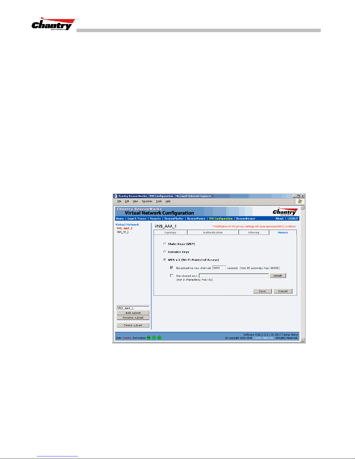
BeaconWorks User Guide – Virtual Network Configuration: A VNS for AAA
The steps in the WPA authentication and encryption process are as follows:
1. The wireless device client associates with BeaconPoint.
2. BeaconPoint blocks the client’s network access while the authentication process is
carried out (the BeaconMaster sends the authentication request to the RADIUS
authentication server)
3. The wireless client provides credentials that are forwarded by the BeaconMaster
to the authentication server.
4. If the wireless device client is not authenticated, the wireless client stays blocked
from network access.
5. If the wireless device client is authenticated, the BeaconMaster distributes
encryption keys to the BeaconPoint and the wireless client.
6. The wireless device client gains network access via the BeaconPoint, sending and
receiving encrypted data. The traffic is controlled with permissions and policy
applied by the BeaconMaster.
Set up Wi-Fi Protected Access privacy (WPA) for an AAA VNS
1. To set up WPA privacy on the VNS, click on the
Screen 43: Virtual Network Configuration – Privacy – AAA VNS: WPA
WPA
radio button.
Specify a re-key interval for WPA Privacy
2. To enable re-keying after a time interval, click the
checkbox on (the default is on). Type in the re-key time interval (the time after
which the broadcast encryption key is changed automatically) in seconds.
If the box is unchecked, the Broadcast encryption key is never changed and the
BeaconPoint will always use the same broadcast key for Broadcast/Multicast
transmissions. Note that this reduces the level of security for wireless
communications.
Chantry Networks Inc. Copyright 2004. All rights reserved. BeaconWorks Rel 2.0 (051304) Page 78 of 134
Broadcast re-key interval
Page 79

BeaconWorks User Guide – Virtual Network Configuration: A VNS for AAA
Enable WPA in PSK mode if there is no authentication server
3. To enable WPA-PSK, for authentication on a network without an authentication
server, click the
Pre-Shared Key
checkbox on.
4. Type in the
Pre-Shared Key
(PSK), or shared secret, to be used between the
wireless device and BeaconPoint. The key should be between 8 and 63 characters.
It is used to generate the 256-bit key.
5. To display the Pre-Shared Key (in order to proofread your entry before saving the
configuration), click on the
Unmask
button again (the button toggles between
Save the privacy parameters for this VNS
6. To save the privacy parameters for the new VNS, click on the
button. To mask the key again, click on the
Mask
and
Unmask
).
Save
button.
Chantry Networks Inc. Copyright 2004. All rights reserved. BeaconWorks Rel 2.0 (051304) Page 79 of 134
Page 80

BeaconWorks User Guide – BeaconMaster Configuration: Availability
BeaconMaster Configuration: Availability
The BeaconWorks system provides a feature that maintains service availability in the
event of a BeaconMaster outage.
The Availability feature links two BeaconMasters as a pair, so that they share
information about their BeaconPoints. If one BeaconMaster in a pair fails, then its
BeaconPoints are allowed to connect instead to the second BeaconMaster. The second
BeaconMaster provides the wireless network and a pre-assigned VNS for the
BeaconPoint.
From the viewpoint of a BeaconPoint, if its home BeaconMaster fails, the
BeaconPoint reboots and begins its discovery process. The BeaconPoint will be
directed to the appropriate second BeaconMaster of the pair.
Note
: The Availability feature relies on SLP and a DHCP server that supports Option
78, as described earlier in the BeaconPoint discovery and registration process. The
Availability feature controls how the paired BeaconMasters register as services with
SLP, in normal operations and in the event of an outage.
The wireless device users that were on the BeaconPoint must log in again and become
authenticated on the second BeaconMaster.
The Availability feature is set up in the
Prepare for setting up the Availability feature
BeaconPoint Registration Mode
screen.
Before you begin, the following preparation should be done:
• choose which BeaconMaster is the primary and which is the secondary
• determine the physical communication link for the TCP/IP connection between the
two BeaconMasters (this is done over TCP port 13907), and ensure that the
interfaces used for this connection are routable
• set up DHCP to support Option 78 for SLP, so that it points to the IP addresses of
both BeaconMasters
Now set up each BeaconMaster separately. One method is as follows:
1. In the
BP Registration
screen, set up each BeaconMaster in “Stand-alone Mode”
and “Secure Mode” (allow only approved BeaconPoints to connect)
2. In the
VNS Configuration, Topology
screen, define a VNS on each BeaconMaster
with the same SSID (but different IP addresses)
3. Associate the appropriate BeaconPoints to each BeaconMaster. The BeaconPoints
will appear on each BeaconMaster as “Pending” in the
Access Approval
screen.
4. In the
described below.
5. On each BeaconMaster in the
relevant BeaconPoints from “Pending” to “Approved”.
Chantry Networks Inc. Copyright 2004. All rights reserved. BeaconWorks Rel 2.0 (051304) Page 80 of 134
BP Registration
screen, now enable the two BeaconMasters as a pair, as
Access Approval
screen, change the status of the
Page 81
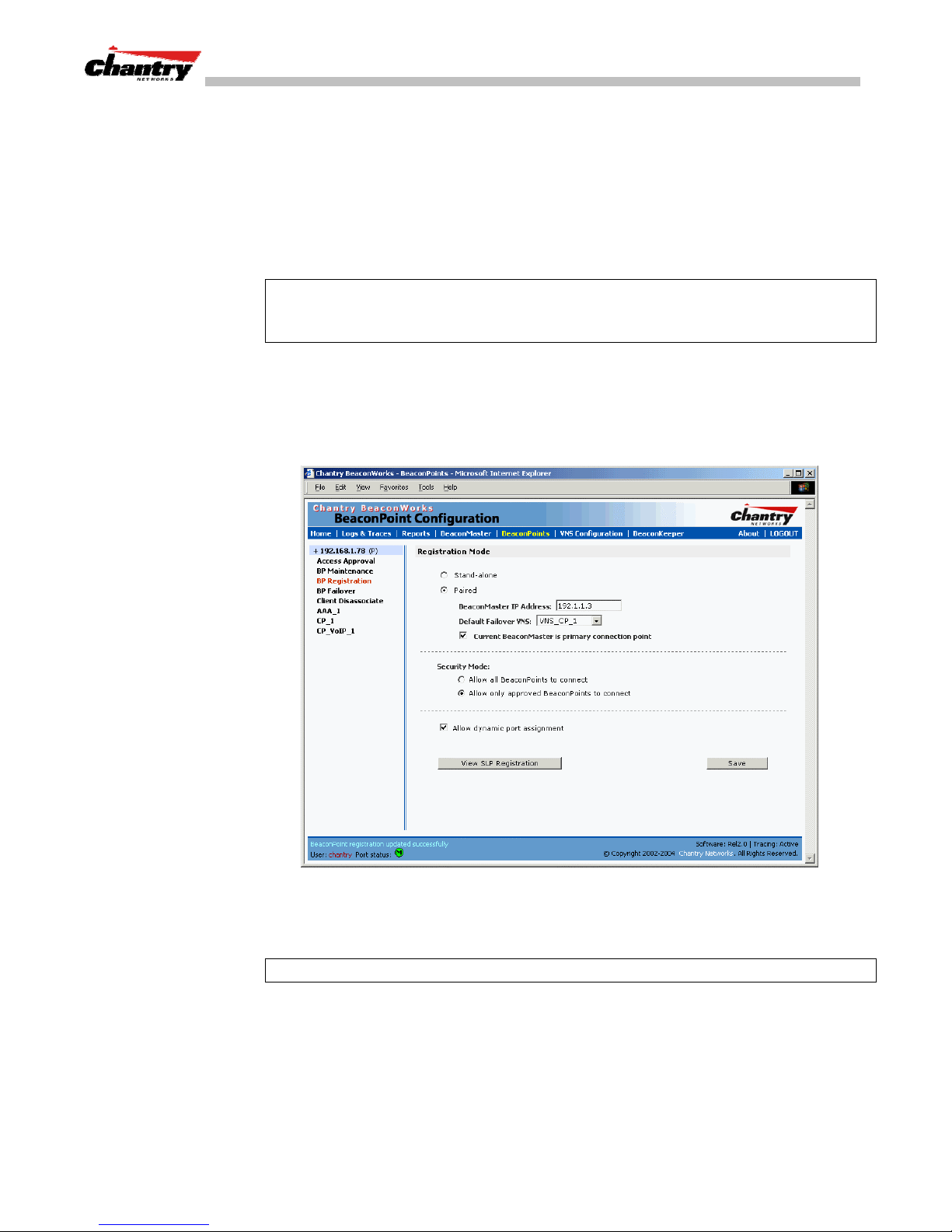
BeaconWorks User Guide – BeaconMaster Configuration: Availability
A second method to set up the BeaconMasters is as follows:
1. In the
BP Registration
screen, enable the two BeaconMasters as a pair, as
described below.
2. Add each BeaconPoint manually to each BeaconMaster. (Select the
tab. In the
BeaconPoint Configuration
The
click on the
Note: Caution:
BeaconPoint Properties
screen, click on the
subscreen appears. Define the BeaconPoint and
Add BeaconPoint
button.)
If two Beacon Masters are paired and one BeaconMaster has the
Add BeaconPoint
BeaconPoint
button.
“Allow All” option set for BeaconPoint registration, all BeaconPoints will register
with that BeaconMaster.
Set up two BeaconMasters as a pair, for availability
1. On the BeaconMaster that is to be the primary, select
screen. Then, in the left-hand list, click on
Registration Mode
screen appears.
BP Registration
BeaconPoints
BeaconPoint
. The
tab in any
Screen 44: BeaconPoint Configuration – Paired BeaconMasters for Availability
2. Click the
3. Enter the
Note:
This IP must be on a routable subnet between the two BeaconMasters.
4. Select a
list of VNS’s (this list will be populated only after a VNS has been defined).
5. Since this BeaconMaster is to be the
checkbox on.
6. Set the
[recommended after initial set up for paired BeaconMasters]
Chantry Networks Inc. Copyright 2004. All rights reserved. BeaconWorks Rel 2.0 (051304) Page 81 of 134
Paired
IP address
Default Failover VNS
Security Mode
radio button.
of the physical port of the secondary BeaconMaster.
to “Allow Approved” by clicking the radio button.
on the other BeaconMaster from the drop-down
primary connection point
, click the
Page 82
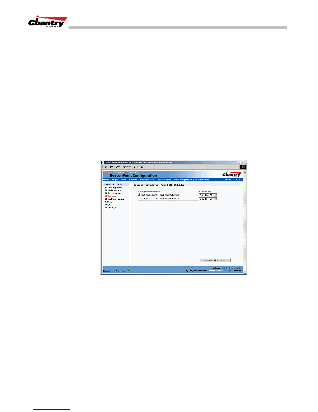
BeaconWorks User Guide – BeaconMaster Configuration: Availability
7. Click the
Allow dynamic port assignment
checkbox on. This ensures that the
BeaconPoint will always find a port for the return connection to its home
BeaconMaster after a failover.
Save
8. To save these settings, click on the
button.
On the BeaconMaster that is to be the secondary one, repeat Steps 1 to 8, with these
exceptions:
• In Step 3, enter the
IP address
of the Management port or physical port of the
primary BeaconMaster.
• In Step 5, leave the
Modifying BP Failover selections for availability
primary connection point
When you have enabled a pair of BeaconMasters as described above,
added as an option in the
1. Click on
BP Failover
BeaconPoint Configuration
option. The
BeaconPoint Failover – Paired BM
checkbox unchecked.
BP Failover
left-hand list.
screen
appears.
is
This screen displays the BeaconPoints registered on the other BeaconMaster of the
pair.
2. For each BeaconPoint, select a
This selection overrides the Default Failover VNS selected in the
Registration Mode
Failover – Paired BM
View the BeaconPoint Availability Report
When the
for the BeaconMaster in Paired Mode, the
the status of both “local” and “foreign” BeaconPoints for that BeaconMaster.
Chantry Networks Inc. Copyright 2004. All rights reserved. BeaconWorks Rel 2.0 (051304) Page 82 of 134
Screen 45: BeaconPoint Configuration – BP Failover for Paired BM
Failover VNS
from the drop-down list.
BeaconPoint
screen. If no VNS is assigned in here in the
BeaconPoint
screen, then the Default Failover VNS will be used.
BeaconPoint Configuration: BP Registration Mode
BeaconPoint Availability
screen has been saved
report will show
Page 83
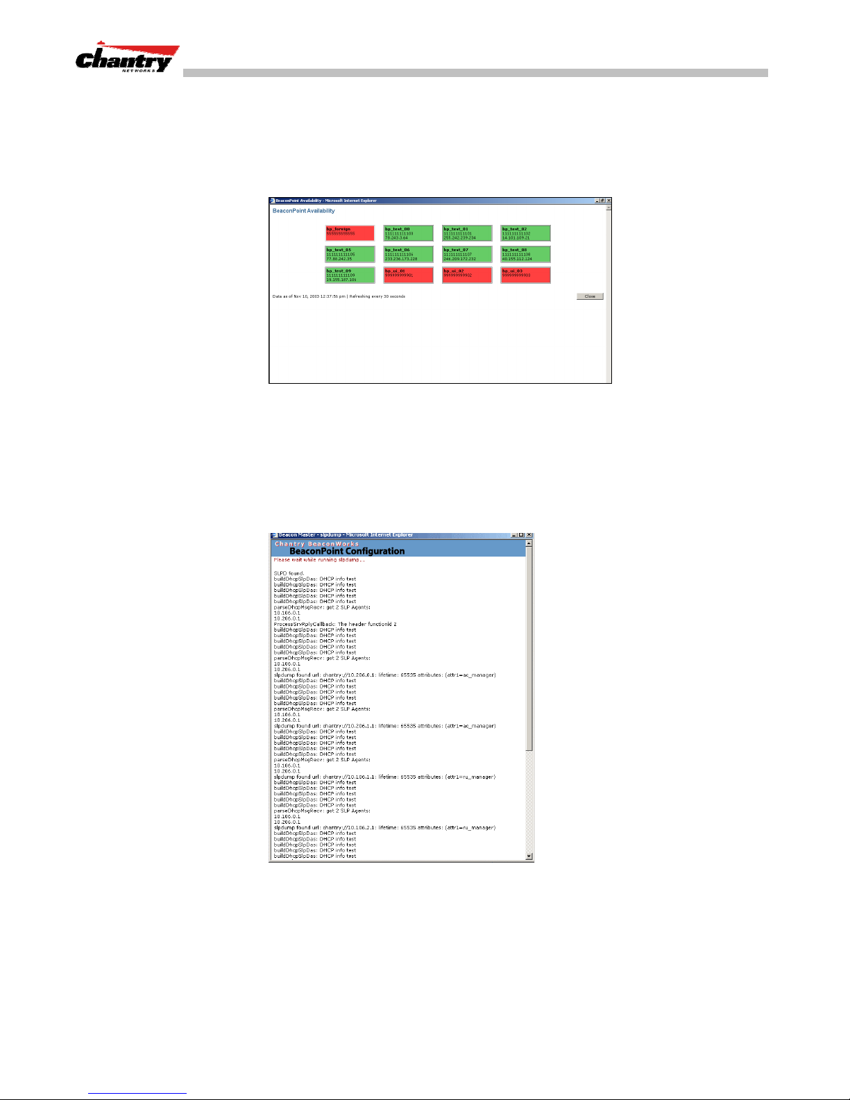
BeaconWorks User Guide – BeaconMaster Configuration: Availability
In normal operations, when Availability is enabled, the “local” BeaconPoints are
green, and the “foreign” BeaconPoints are red. If the other BeaconMaster fails, and
the “foreign” BeaconPoints connect to the current BeaconMaster, then the display will
show all BeaconPoints as green. If the BeaconPoints are not attached they do not
appear in the report.
Screen 46: Report – BeaconPoint Availability
View the SLP activity with the “slpdump tool”
1. Select
2. Click on the
BeaconPoints
Registration
tab in any screen. Then, in the left-hand list, click on
BeaconPoint Registration Mode
. The
View SLP Registration
button. A popup screen displays the results
of the “slpdump tool”, showing the recent SLP activity:
BP
screen appears.
In normal operations, the primary BeaconMaster registers as an SLP service called
“ac_manager” and directs the BeaconPoints to the appropriate BeaconMaster of a
pair. During an outage, if the remaining BeaconMaster is the secondary one, it will
register as an SLP service “ru_manager”.
Chantry Networks Inc. Copyright 2004. All rights reserved. BeaconWorks Rel 2.0 (051304) Page 83 of 134
Screen 47: BeaconPoint configuration – View SLP Registration
Page 84

BeaconWorks User Guide – BeaconMaster Configuration: Availability
Events and actions during a Failover
If one of the BeaconMasters in a pair fails, then the connection between the two
BeaconMasters is lost. This triggers a “Failover mode” condition, and a critical
message appears in the information log of the remaining BeaconMaster.
After the BeaconPoint on the failed BeaconMaster loses its connection, it will attempt
a reboot. Because of the pairing of the two BeaconMasters, the BeaconPoint will then
register with the other BeaconMaster.
Note:
A BeaconPoint connects first to a BeaconMaster registered as “ac_manager”
and, if not found, then seeks an “ru_manager”. If the primary BeaconMaster fails, the
secondary one registers as an SLP service “ru_manager”. This enables the secondary
BeaconMaster to be found by BeaconPoints after they reboot.
When the BeaconPoints connect to the second BeaconMaster, they will be assigned to
the Failover VNS defined in setup in that BeaconMaster. The wireless device users
will log in again and be authenticated on the second BeaconMaster.
When the failed BeaconMaster recovers, each BeaconMaster in the pair goes back to
normal mode. They exchange information that includes the latest lists of registered
BeaconPoints. The administrator will release the BeaconPoints on the second
BeaconMaster, so that they may re-register with their home BeaconMaster.
To support the Availability feature during a “Failover” event, administrator will need
to perform the following actions:
1. Monitor the critical messages in the information log of the remaining
BeaconMaster for the “Failover mode” message (in the
Reports and Displays
area
of the user interface).
2. After recovery, on the BeaconMaster that did not fail, select the “foreign”
BeaconPoints and click on the
– BP Maintenance
screen).
Release
button (in the
BeaconPoint Configuration
Chantry Networks Inc. Copyright 2004. All rights reserved. BeaconWorks Rel 2.0 (051304) Page 84 of 134
Page 85

BeaconWorks User Guide – BeaconMaster Configuration: Mobility and the VN Manager
BeaconMaster Configuration: Mobility and the VN Manager
The BeaconWorks system has a technique by which multiple BeaconMasters on a
network can discover each other and exchange information about a client session. This
enables a wireless device user to roam seamlessly between different BeaconPoints on
different BeaconMasters.
The solution introduces the concept of a “VN Manager”. This means that one
BeaconMaster on the network must be designated as the “VN Manager”. All other
BeaconMasters are designated as “VN Agents”. To define whether the BeaconMaster
is a Manager or an Agent, use the
Configuration area.
The wireless device will keep the IP address, VNS assignment and filtering rules that
it received from the BeaconMaster that it first connected to – its “home”
BeaconMaster. (This information is collected in the
the home BeaconMaster.) The VNS on each BeaconMaster must have the same SSID.
If the VNS has static WEP, it is recommended that the same key be used.
Note:
The “VN Manager” concept relies on SLP and DHCP. Before you begin, you
must ensure that the DHCP server on your network supports Option 78. These are also
used during the BeaconPoint discovery process, and are explained in that topic earlier
in this Guide.
VN Manager
screen in the BeaconMaster
Active Clients by VNS
display on
VN Manager and VN Agent: Background
The BeaconMaster that is the “VN Manager”:
• uses SLP to register itself as a service with the SLP Directory Agent
• listens for connection attempts from “VN Agents”
• if it receives a connection attempt from “VN Agent”, it establishes connection and
sends a message to the “VN Agent” specifying the Heartbeat interval, and the VN
Manager’s IP address.
• sends regular Heartbeat messages (which contain wireless device session changes
and Agent changes) to the VN Agents and waits for an Update message back
• if it fails to receive an Update from the VN Agent after three Heartbeat messages,
it sends a Disconnect message to the VN Agent, removes all wireless device users
associated with that VN Agent BeaconMaster from its tables and closes down the
connection.
The BeaconMaster that is a “VN Agent”:
• uses SLP to find the location of the VN Manager
• attempts to establish a TCP/IP connection with the VN Manager
• when it receives the connection-established message (see above), it updates its
tables, and sets up data tunnels to and between all BeaconMasters it has been
informed of
• after every Heartbeat massage received, it uses the information to update its own
tables and then sends an Update message to the VN Manager, with updates on
wireless device users and data tunnels it is managing.
Chantry Networks Inc. Copyright 2004. All rights reserved. BeaconWorks Rel 2.0 (051304) Page 85 of 134
Page 86
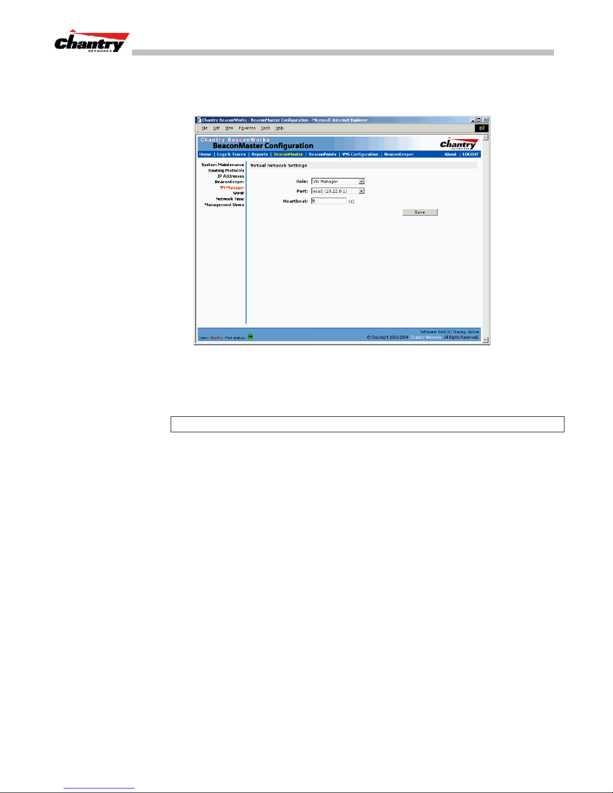
BeaconWorks User Guide – BeaconMaster Configuration: Mobility and the VN Manager
Set up a BeaconMaster as a VN Manager
1. In the
BeaconMaster Configuration
Virtual Network Settings for VN Manager
Screen 48: BeaconMaster Configuration – VN Manager
2. From the
Role
drop-down list, select
screen, click on the
screen appears.
VN Manager
(other options: None, Agent).
VN Manager
option. The
Port
3. From the drop-down list, select the
on the BeaconMaster to be used by the
VN Manager process.
Note:
Ensure that the port selected is routable on the network.
4. In the
Heartbeat
field, type in the time interval at which the VN Manager sends a
Heartbeat message to a VN Agent. The default is 5 seconds.
Save
5. To save these settings, click on the
button.
If you set up one BeaconMaster on the network as a “VN Manager”, then all other
BeaconMasters must be set up as “VN Agents”. In the
Role
drop-down list, select
Agent
. The
Heartbeat
VN Manager
screen, in the
value, for a “VN Agent”, is how
long to wait for a connection establishment response before trying again.
View displays when VN Managers is enabled
When a BeaconMaster has been configured as a VN Manager, three additional
displays are available in the
List of Displays
screen:
Chantry Networks Inc. Copyright 2004. All rights reserved. BeaconWorks Rel 2.0 (051304) Page 86 of 134
Page 87
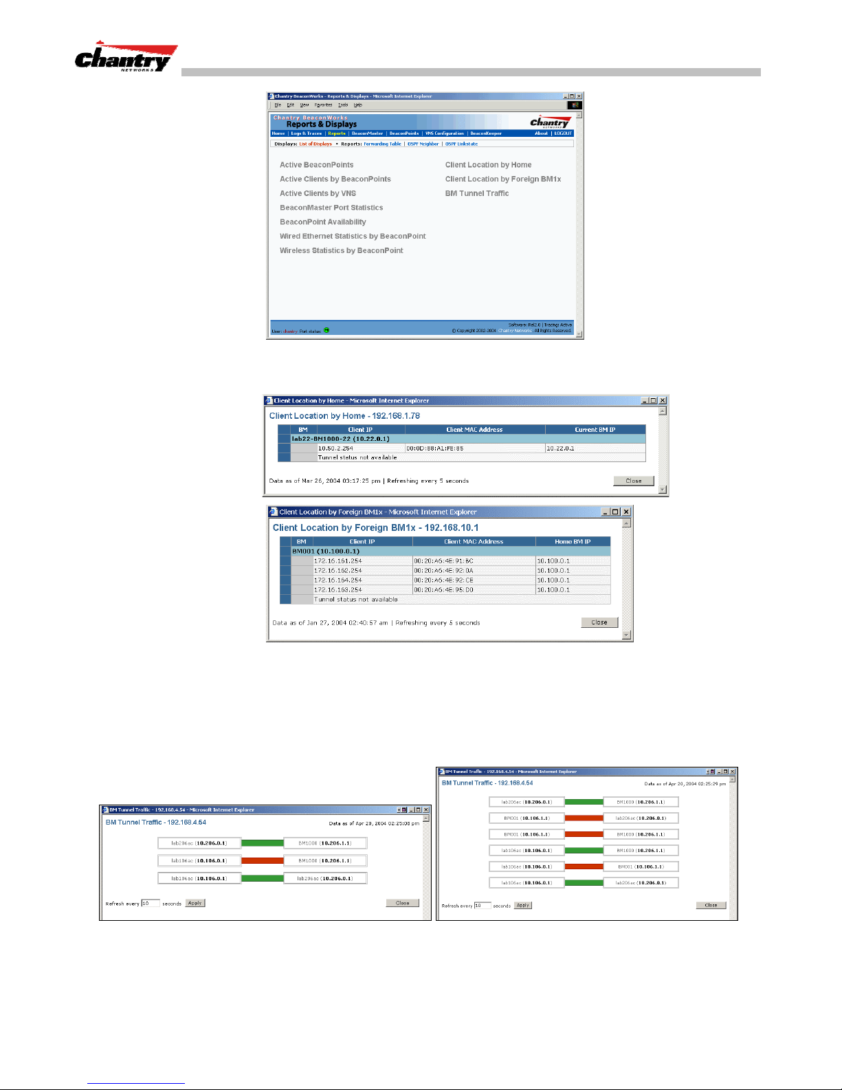
BeaconWorks User Guide – BeaconMaster Configuration: Mobility and the VN Manager
Screen 49: Reports and Displays for a VN Manager: Menu
Screen 50: Reports and Displays for a VN Manager: Examples
To view the status of the tunnels between the BeaconMasters, click on the BM Tunnel
Traffic display option. This screen displays the BeaconMasters known to the VN
Manager. If a tunnel is active, a green band is displayed between BeaconMasters. A
red band indicates that there is no traffic on the tunnel. If the BeaconMasters are not
displayed, the tunnel is inactive.
Screen 51: Reports and Displays for a VN Manager: BM Tunnel Traffic
Active Clients by VNS
The
BeaconMasters of for all BeaconPoints, and for the wireless devices that travel, if they
are on the same SSID.
Chantry Networks Inc. Copyright 2004. All rights reserved. BeaconWorks Rel 2.0 (051304) Page 87 of 134
display also collects information on the VN Manager
Page 88
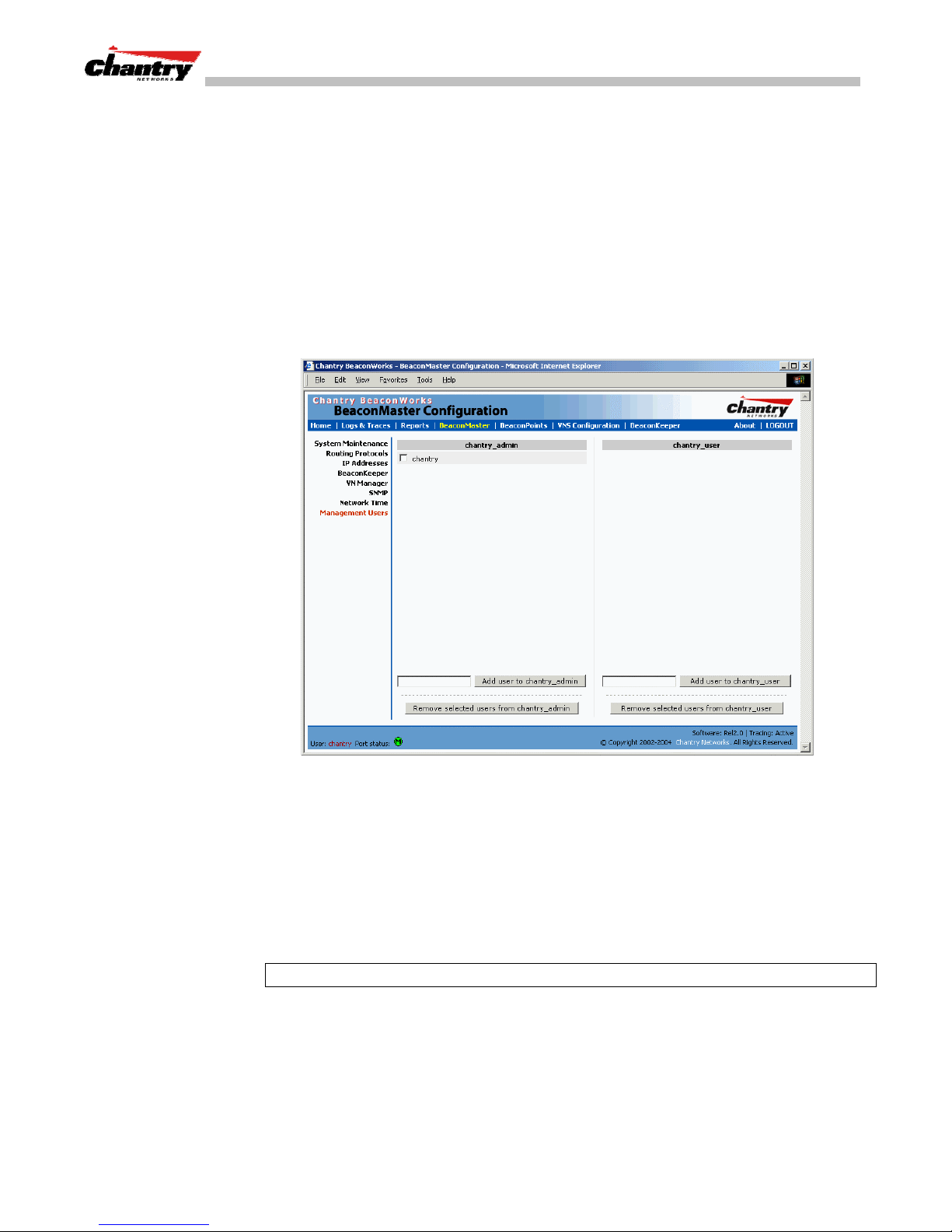
BeaconWorks User Guide – BeaconMaster Configuration: Management Users
BeaconMaster Configuration: Management Users
In this screen you define the login usernames that have access to the GUI, either for
Administrators with “read/write” privileges, or other users with “read only”
privileges.
Designate BeaconMaster management users
1. Click on the
BeaconMaster
tab in any screen. The
screen appears.
2. In the left-hand portion of the screen, click on the
Management Users
The
screen appears. .
BeaconMaster Configuration
Management Users
option.
The list on the left is for “Admin” users who have read/write privileges. The righthand list is for users who have “read only” privileges.
To add a User ID, type it in the entry field (on the appropriate side) and click on the
Add user...
To delete a User ID, click in its checkbox to select it, and then click on the
selected user...
Note:
A User ID can only be used once, in only one of these two lists.
Chantry Networks Inc. Copyright 2004. All rights reserved. BeaconWorks Rel 2.0 (051304) Page 88 of 134
Screen 52: BeaconMaster Configuration – Management Users
button.
Remove
button.
Page 89
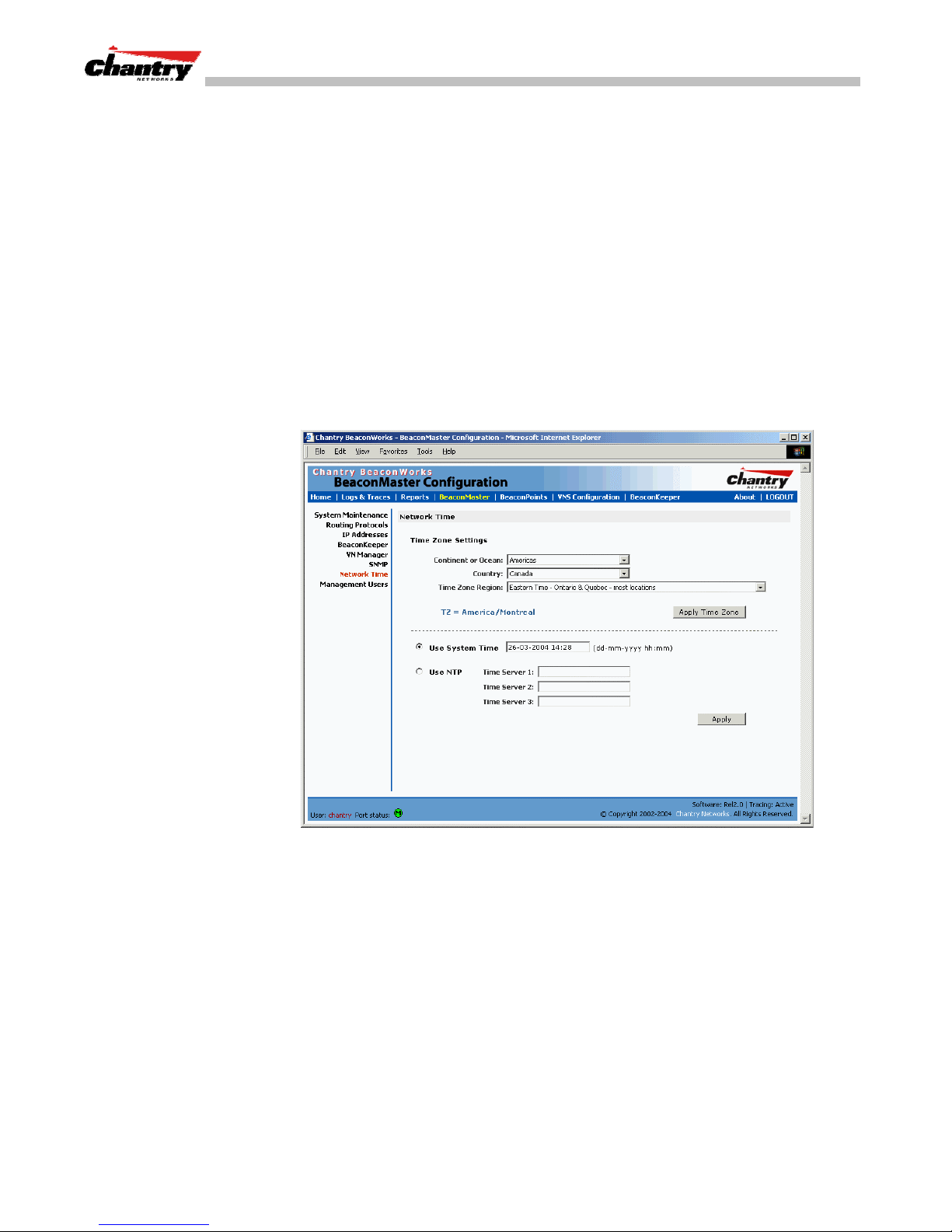
BeaconWorks User Guide – BeaconMaster Configuration: Network Time
BeaconMaster Configuration: Network Time
Use the Network Time screen to synchronize the elements on the network to a
universal clock. This ensures accuracy in usage logs.
The Network Time screen synchronizes in one of two ways:
• using system time
• using Network Time Protocol (NTP), an Internet standard protocol that
synchronizes client workstation clocks.
Set Network Time parameters
1. Click on the
BeaconMaster
tab in any screen. The
screen appears.
2. In the left-hand portion of the screen, click on the
Network Time
screen appears.
BeaconMaster Configuration
Network Time
option. The
3. From the drop-down list, select the
geographic grouping.
4. From the drop-down list, select the
contents of the list will change based on the selection in the previous field).
5. From the drop-down list, select the
6. To apply these time zone settings, click on the
7. To use System Time, click on its radio button. Type in the time setting.
8. To use Network Time Protocol, click on the
location (IP address) of up to three standard NTP Time Servers.
9. To apply these settings, click on the
Chantry Networks Inc. Copyright 2004. All rights reserved. BeaconWorks Rel 2.0 (051304) Page 89 of 134
Screen 53: BeaconMaster Configuration – Network Time
Continent
Country
Time Zone Region
Apply
Ocean
or
, the large-scale
, within the previous group (the
for the country selected.
Apply Time Zone
NTP
radio button. Then fill in the
button.
button
Page 90
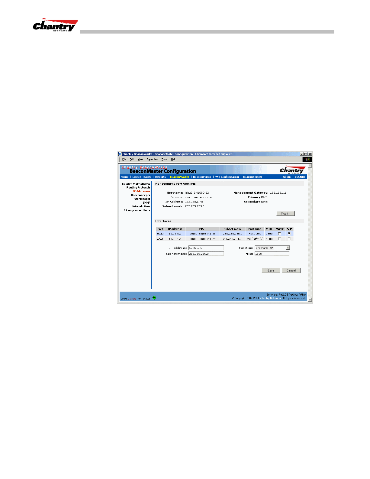
BeaconWorks User Guide – Setting up Third-Party Access Points
Setting up Third-Party Access Points
Your enterprise’s WLAN may have existing third-party access points that you would
like to integrate into the Chantry WLAN solution. You can set up the BeaconMaster
to handle wireless device traffic from third-party access points, providing the same
policy and network access control.
Set up third-party access points on the BeaconMaster
1. Define one data port as a “3rd-party AP” port:
BeaconMaster Configuration
In the
Management Port Settings and Interfaces
appropriate port, and in the
down list. Make sure that Management Traffic and SLP are disabled for this port.
Function
screen, click on the
IP Address
option. The
screen appears. Highlight the
field, select “3rd-party AP” from the drop-
2. Connect the third-party access point to this port, via a switch.
3. Define a static route to the access point:
In the
option. Then click the
Define a static route to the access point (see Routing topic earlier).
4. Set up a VNS for the “3rd-party AP” port:
In the
VNS name in the left-hand list and click on the
Chantry Networks Inc. Copyright 2004. All rights reserved. BeaconWorks Rel 2.0 (051304) Page 90 of 134
Screen 54: BeaconMaster Configuration – IP Addresses / Interfaces
BeaconMaster Configuration
Static Routes
Virtual Network Configuration
screen, click on the
tab. The
Static Routes
screen, add a new VNS. Then highlight the
Topology
Routing Protocols
screen appears.
tab.
Page 91
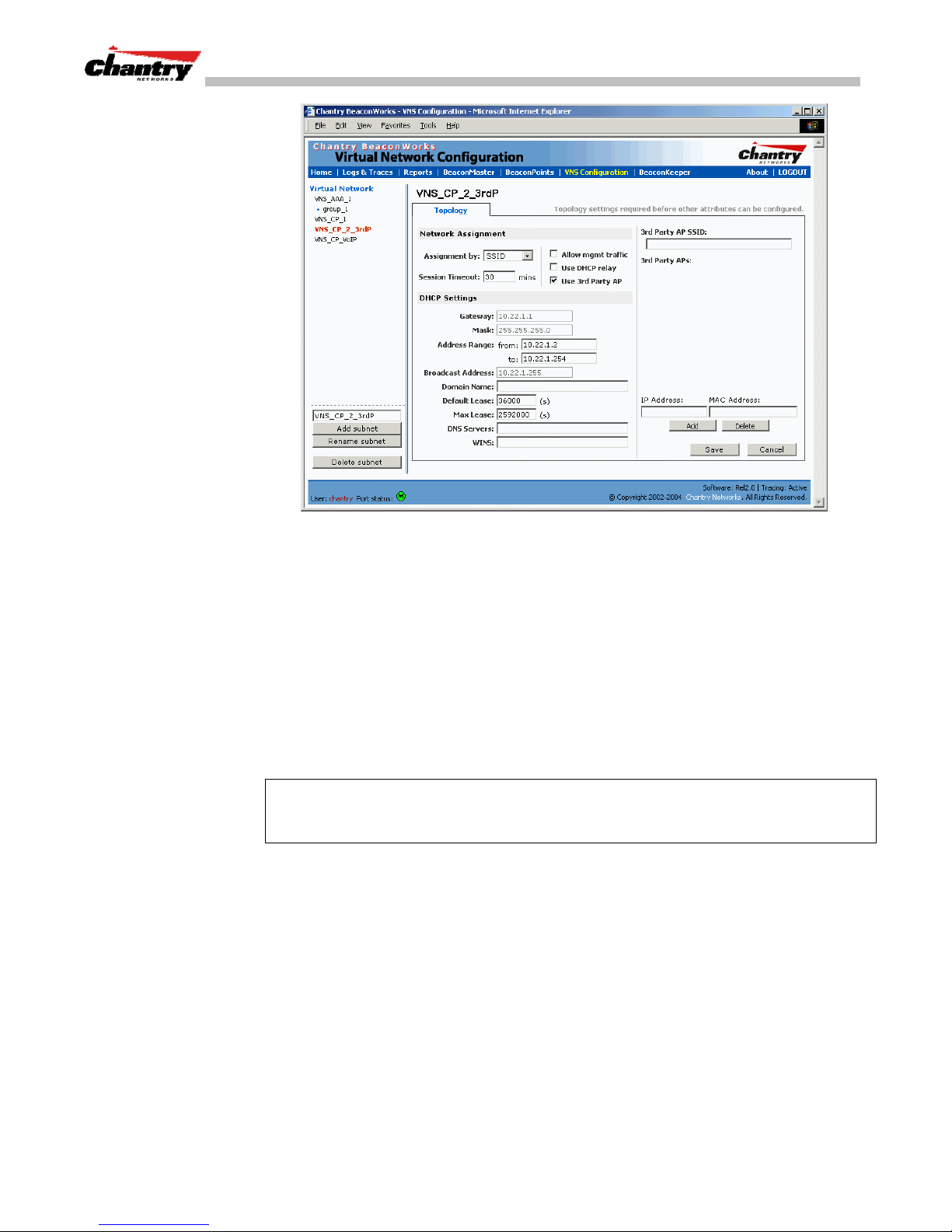
BeaconWorks User Guide – Setting up Third-Party Access Points
Screen 55: Virtual Network Configuration – Topology for Third-Party APs
In the Topology screen, select
Click on the
Fill in the
Use 3rd Party AP
IP Address
and
addresses of the third party access points, and click on the
Assignment by SSID
checkbox to select it.
MAC Address
entry fields that appear on the right (the
.
Add
button. They will
appear in the list of access points known to the BeaconMaster.
Follow the remaining steps described in the setting up a VNS for Captive Portal
earlier in this Guide.
5. Set up Authentication by Captive Portal for the “3rd-party AP” VNS:
Click on the
Captive Portal
the
Authentication
tab. In the
radio button. In the Captive Portal portion of the screen, define
Authentication
configuration screen, click
the RADIUS Attributes and the Filter IDs to match those in RADIUS..
Note:
Alternatively, for third-party APs, you can define network assignment by AAA,
and authentication by 802.1x. The RADIUS requests from the third-party access point
will flow through the BeaconMaster.
6. Set up filtering rules for Filter IDs for the 3rd-Party APs:
Virtual Network Configuration
In the
Filtering
screen appears. Click on the subnet name in the left-hand list.
screen, click on the
Filtering
tab. The
Define filtering rules that allow access to other services and protocols on the
network such as HTTP, FTP, Telnet, SNMP.
In addition, modify the following functions on the third-party access point:
• Disable the access point’s DHCP server, so that the IP address assignment for any
wireless device on the AP is from the DHCP server at the BeaconMaster with VNS
information
• Disable the third-party access point’s layer 3 IP routing capability and set the
access point to work as a layer 2 bridge.
Chantry Networks Inc. Copyright 2004. All rights reserved. BeaconWorks Rel 2.0 (051304) Page 91 of 134
Page 92

BeaconWorks User Guide – Setting up Third-Party Access Points
Here are the differences between third-party access points and BeaconPoints on the
BeaconWorks system:
• An access point exchanges data with the BeaconMaster’s data port using standard
IP over ethernet protocol. The third-party access points do not support the
CAPWAP Tunnelling Protocol (CTP) header for encapsulation.
• For third-party access points, the VNS is mapped to the physical data port and this
is the default gateway for mobile units supported by the third-party access points.
• A BeaconMaster cannot directly control or manage the configuration of an access
point.
• Access points are required to broadcast an SSID unique to their segment. This
SSID cannot be used by any other VNS.
• Roaming from access points to BeaconPoints not supported.
Chantry Networks Inc. Copyright 2004. All rights reserved. BeaconWorks Rel 2.0 (051304) Page 92 of 134
Page 93
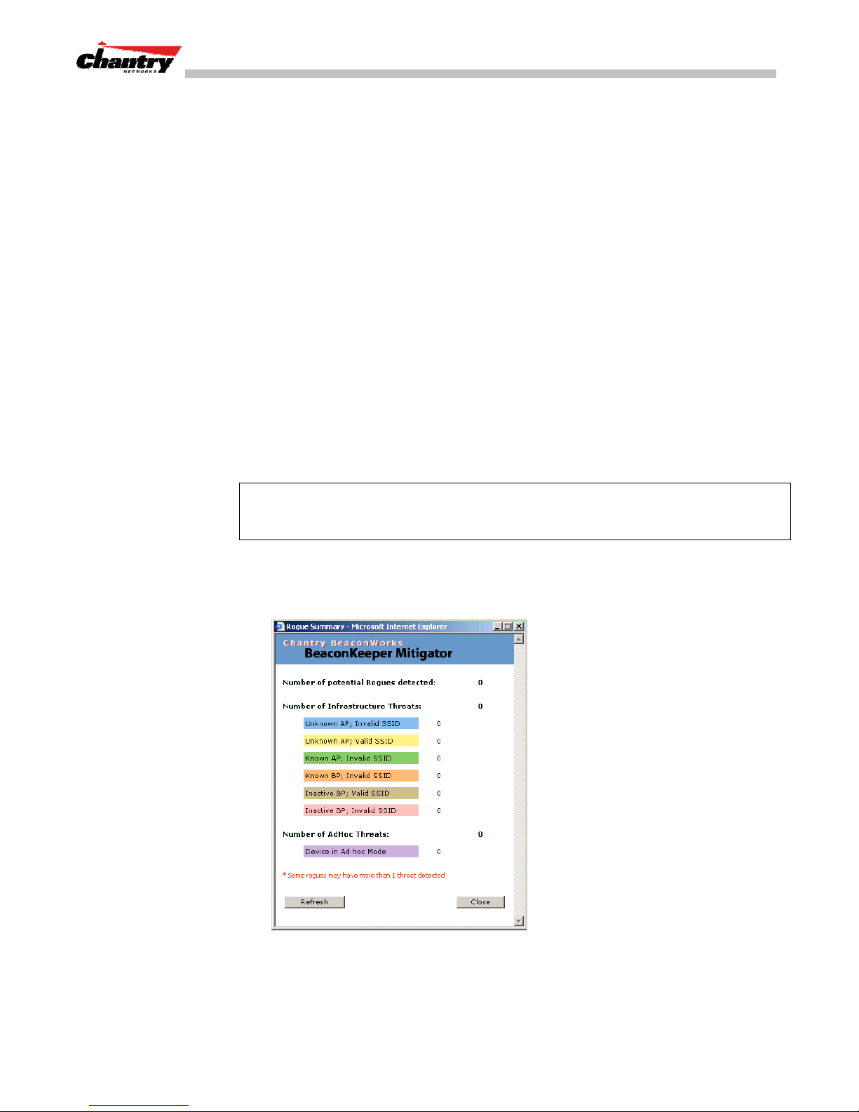
BeaconWorks User Guide – BeaconKeeper Mitigator: Detecting Rogue Access Points
BeaconKeeper Mitigator: Detecting Rogue Access Points
BeaconKeeper Mitigator: Overview
The BeaconWorks system (Release 2.0) includes a mechanism that assists in the
detection of rogue access points. The function is called the BeaconKeeper Mitigator.
Th BeaconKeeper Mitigator feature has three components:
radio frequency (RF) scanning task
•a
BeaconPoint itself functions as a scan device. Its scan function alternates with
providing its regular service the wireless devices on the network. You set up the
scan parameters in the BeaconKeeper user interface.
that runs on the BeaconPoint. The
• an application called the
RF Data Collector (RFDC)
on the BeaconMaster that
receives and manages the RF scan messages sent by the BeaconPoint. The scan
data includes lists of all connected BeaconPoints, third Party APs and other
friendly APs and the RF scan information that has been collected from the
BeaconPoints.
Analysis Engine
•an
on the BeaconMaster that processes the scan data from the
RFDC through algorithms that make decisions about whether a detected access
point is a rogue access point.
Note:
In a network with more than one BeaconMaster, the analysis engine should be
active on only one BeaconMaster that communicates with the RFDC applications
running on itself and on the other BeaconMasters on the network.
The BeaconKeeper Mitigator function must be enabled in the user interface. Before it
is enabled, the
BeaconKeeper
menu item in the main menu, or the
tab in any screen will only access a popup
Rogue Summary
report screen:
BeaconKeeper
To enable the BeaconKeeper Mitigator, use the menu option in the
Configuration
Chantry Networks Inc. Copyright 2004. All rights reserved. BeaconWorks Rel 2.0 (051304) Page 93 of 134
Screen 56: BeaconKeeper Mitigator – Rogue Summary Report
BeaconMaster
area of the user interface.
Page 94
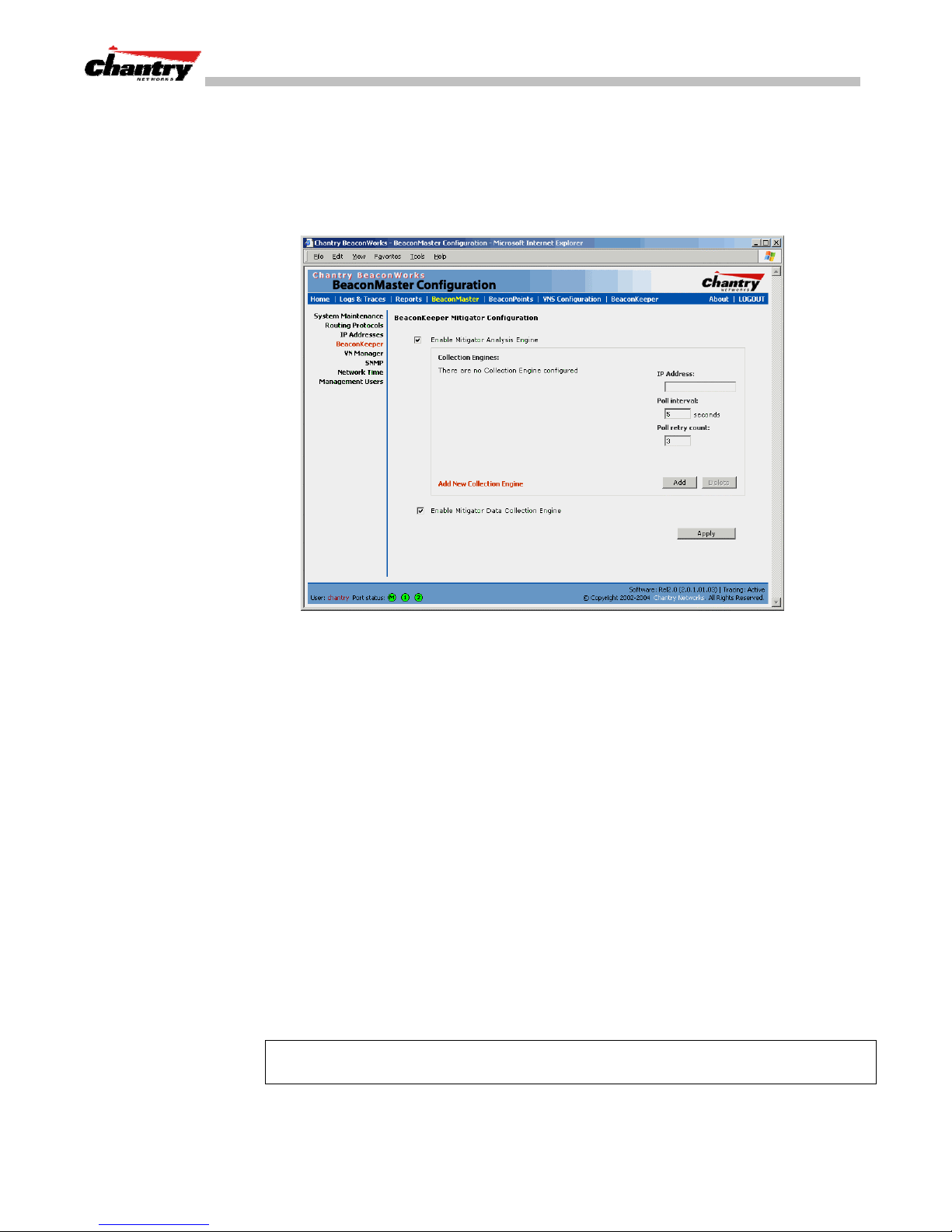
BeaconWorks User Guide – BeaconKeeper Mitigator: Detecting Rogue Access Points
BeaconKeeper Mitigator: Enabling the Analysis and RFDC Engines
Enable and configure the BeaconKeeper Mitigator Analysis Engine
1. Click on
BeaconMaster
tab in any screen. The
of the user interface appears. In the left-hand list, click on the
option. The
Screen 57: BeaconMaster Configuration – BeaconKeeper Mitigator Configuration
BeaconKeeper Mitigator Configuration
BeaconMaster Configuration
BeaconKeeper
screen appears.
area
2. To enable the
Define the BeaconKeeper Mitigator RF Data Collector Engines
3. To enable the
Mitigator Analysis Engine
Mitigator Data Collection Engine
, click the checkbox on.
on this BeaconMaster click the
checkbox on.
4. Identify the remote RF Data Collector Engines that the Analysis Engine will poll
for data: In the
Collection Engine IPs
entry field, key in the IP address of the
BeaconMaster on which the remote RFDC resides. (For this BeaconMaster, the
local IP address is displayed by default.)
5. For each data collection engine, enter:
•In the
Poll interval
field (he interval that the Analysis Engine polls the RF
Data Collector for data), key in the time in seconds. Default is 30 seconds.
•In the
Poll retry count
field, key in the number of times the Analysis Engine
will attempt to poll the RF Data Collector for data before it stops sending
requests. Default is 2 attempts.
Add
6. Click on the
button. The IP address of the Data Collection Engine, with its
Poll Interval and Poll Retry parameters, appears in the list.
Note:
For each remote RF Data Collection Engine you define here, you must also
enable it (click the checkbox on) in the same screen on the remote BeaconMaster.
Chantry Networks Inc. Copyright 2004. All rights reserved. BeaconWorks Rel 2.0 (051304) Page 94 of 134
Page 95
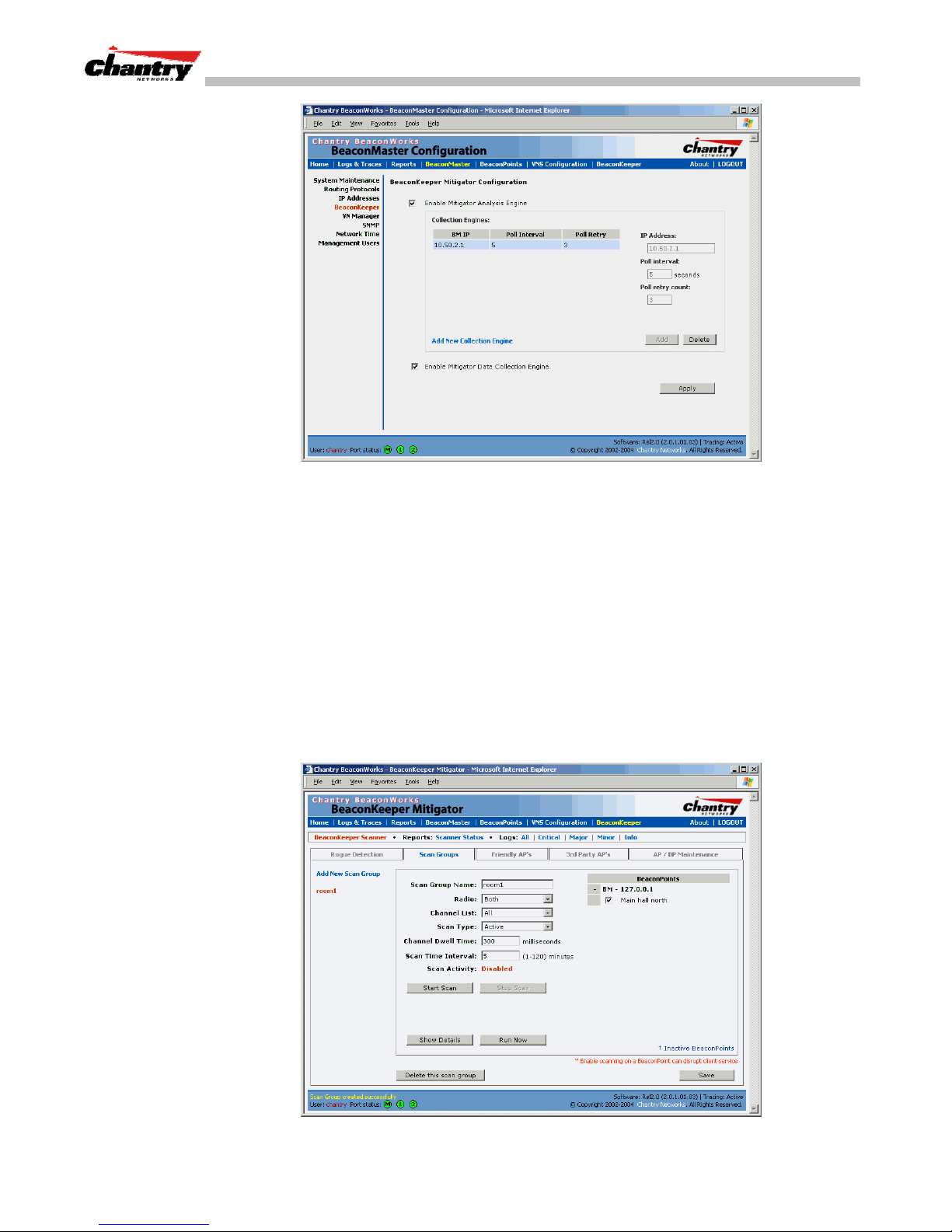
BeaconWorks User Guide – BeaconKeeper Mitigator: Detecting Rogue Access Points
Screen 58: BeaconMaster Configuration – BeaconKeeper Mitigator: Collection Engines
7. To clear the entry fields and add a new Collection Engine, click on the
Collection Engine
option. Repeat steps 4 to 6 above.
8. To save these settings, click on the
BeaconKeeper Mitigator: Running Scans
After enabling the BeaconKeeper engines (as described above), click the
BeaconKeeper
menu item in the main menu, or the
screen. The BeaconKeeper Scanner screen appears, with five tabs.
Set up and run the BeaconKeeper Mitigator scan task mechanism:
1. To set up the parameters of the scan task mechanism, click on the
tab. The
Scan Groups
screen appears.
Apply
button.
BeaconKeeper
Add
tab in any
Scan Groups
Chantry Networks Inc. Copyright 2004. All rights reserved. BeaconWorks Rel 2.0 (051304) Page 95 of 134
Screen 59: BeaconKeeper Mitigator Scanner – Scan Groups
Page 96
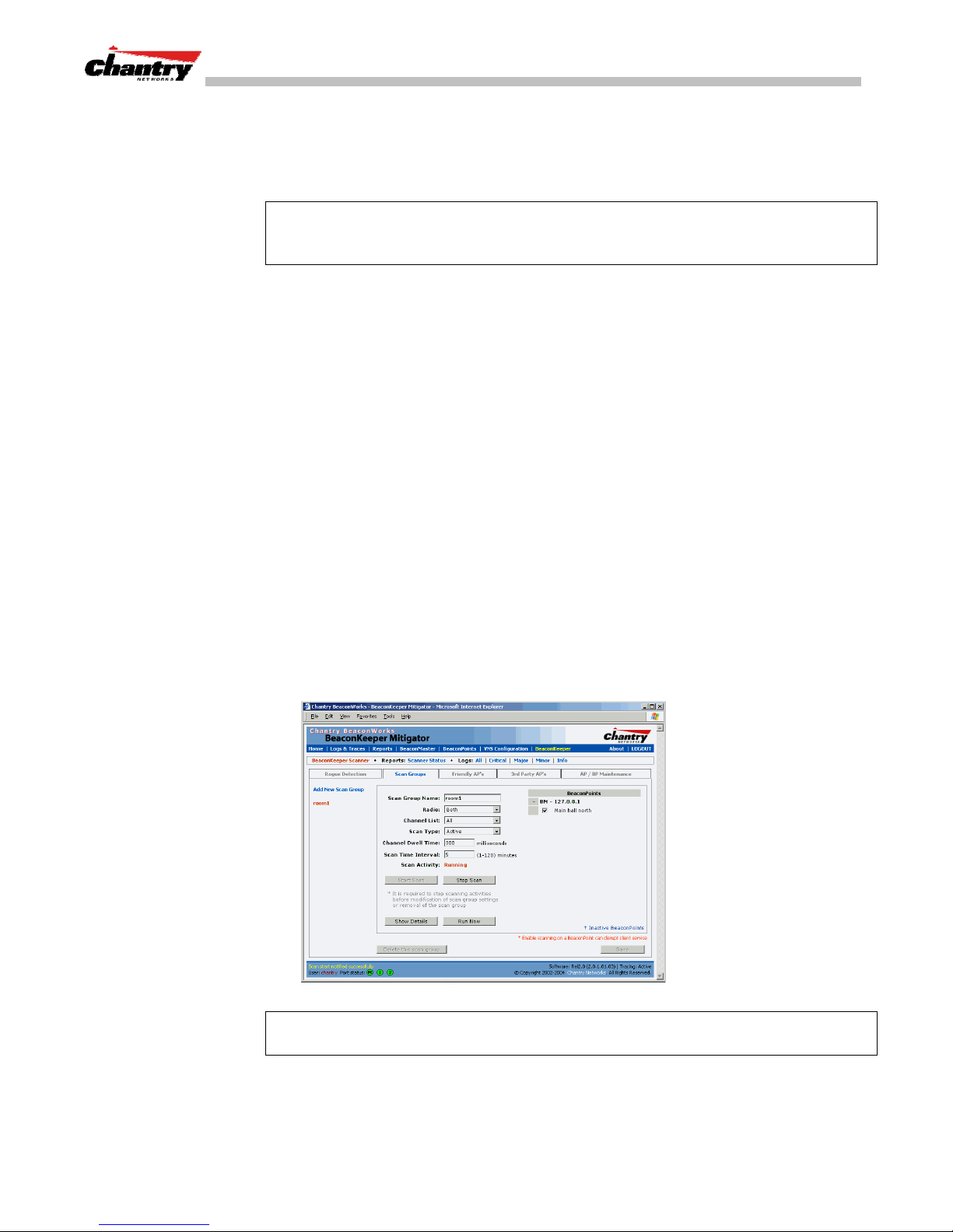
BeaconWorks User Guide – BeaconKeeper Mitigator: Detecting Rogue Access Points
3. In the
4. In the
Scan Group Name
BeaconPoints
area, clicking the checkbox on to select the BeaconPoint (or
entry field, key in a name for this Scan Group.
BeaconPoints) that will be included in this Scan Group and will perform the scan
function.
Note:
A BeaconPoint can participate in only one Scan Group at a time.
It is recommended that the Scan Groups represent geographical groupings of
BeaconPoints.
5. In the
Radio
field, from the drop-down list select which radios on the
BeaconPoint are to perform the scan function Both, A only, B/G only.
6. In the
scan on:
7. In the
Channel List
All
, or
Scan Type
field, from the drop-down list select the radio channels to
Current
.
field, from the drop-down list select either
Active
or
• Active: the BeaconPoint sends out ProbeRequests and waits for
ProbeResponse messages from any access points.
• Passive: the BeaconPoint listens for 802.11 beacons
8. In the
Channel Dwell Time
field, key in the time in milliseconds that the scanner
waits for a response (either for 802.11 beacons in passive scanning, or
ProbeResponse in active scanning).
Passive
.
9. In the
Scan Time Interval
field, key in the time in minutes {1 to 120}, to define
the frequency at which a BeaconPoint within the Scan Group will initiate a scan
of the RF space.
10. To start a scan, using the periodic scanning parameters defined above, click on the
Start Scan
11. To initiate an immediate scan on request, click on the
12. To stop the scan, click on the
button
Stop Scan
button.
Run Now
button.
Note:
You must stop the scan before modifying any parameters of the Scan Group, or
before adding or removing a BeaconPoint from a Scan Group.
13. The
Chantry Networks Inc. Copyright 2004. All rights reserved. BeaconWorks Rel 2.0 (051304) Page 96 of 134
Scan Activity
field displays the current state of the scan engine.
Page 97

BeaconWorks User Guide – BeaconKeeper Mitigator: Detecting Rogue Access Points
14. To view a popup report showing the timeline of scan activity and results, click on
Show Details
the
BeaconKeeper Mitigator: How the Analysis Engine works
button.
The Analysis Engine relies on a database of known devices on the BeaconWorks
system as follows:
• BeaconPoints registered with any BeaconMaster that has its RF Data Collector
enables and has been associated with the Analysis Engine on this BeaconMaster.
• Third-Party Access Points that have been defined and assigned to a VNS (as
described earlier in this Guide).
• Friendly APs, a list created in the BeaconKeeper Mitigator user interface as
potential rogue access points are designated by the administrator as “Friendly”.
The Analysis Engine compares the data from the RF Data Collector with the above
database of known devices.
The Analysis Engine looks for access points with seven conditions:
• unknown MAC address and unknown SSID (critical alarm)
• unknown MAC, with a valid SSID – a known SSID is being broadcast by the
unknown access point (critical alarm)
• known MAC, with an unknown SSID – a rogue may be spoofing a MAC address
(critical alarm)
• inactive BeaconPoint with valid SSID (critical alarm)
• inactive BeaconPoint with unknown SSID (critical alarm)
• known BeaconPoint with an unknown SSID (major alarm)
• in ad-hoc mode (major alarm).
Note:
In Release 2.0, there is no capability to initiate a DoS attack on the detected
rogue access point. Containment of a detected rogue will require an inspection of the
geographical location of its Scan Group area (where its RF activity has been found).
View the BeaconKeeper scan results and build list of Friendly APs
1. Click on the
Detection
tab. The
BeaconKeeper
Rogue Detection
tab in any screen Then click on the
screen appears displaying all access points
Rogue
and BeaconPoints that were found in the scan but are not in the database of known
devices (as defined above).
2. To modify the rate that this information is refreshed, key in a time in seconds and
Apply
click on the
button.
Note: The
described earlier in this Guide.
Chantry Networks Inc. Copyright 2004. All rights reserved. BeaconWorks Rel 2.0 (051304) Page 97 of 134
Rogue Summary
button accesses the
Rogue Summary
popup report
Page 98
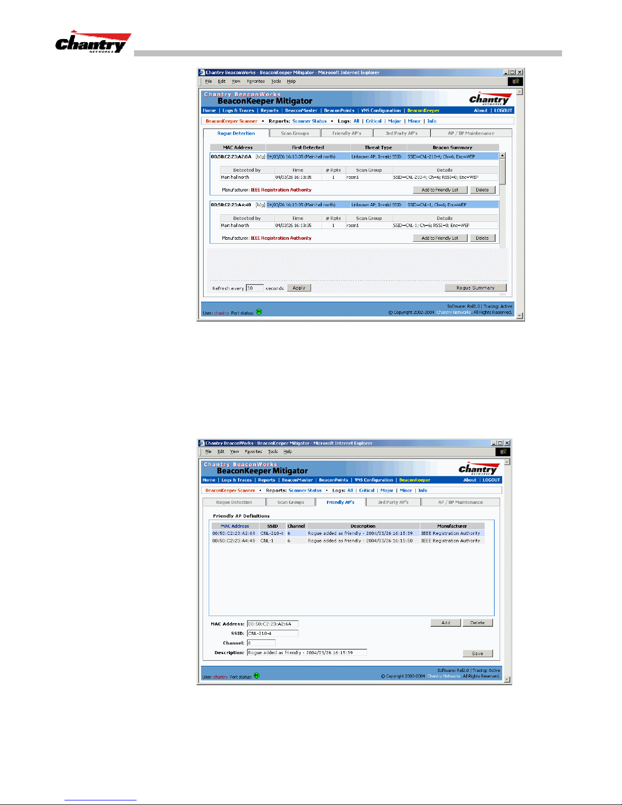
BeaconWorks User Guide – BeaconKeeper Mitigator: Detecting Rogue Access Points
Screen 60: BeaconKeeper Mitigator Scanner – Rogue Detection
3. To remove an access point from this list, click on the
4. To add an access point or BeaconPoint to the
to Friendly List
will appear in the
5. To view the Friendly list, click on the
Definitions
button. The access point item will be removed from this list and
Friendly APs
list.
Friendly APs
screen appears.
Friendly APs
Delete
list, click on the
tab. The
button.
Add
Friendly AP
6. To add friendly access points manually to the
the
Click on the
Chantry Networks Inc. Copyright 2004. All rights reserved. BeaconWorks Rel 2.0 (051304) Page 98 of 134
Screen 61: BeaconKeeper Mitigator Scanner – Friendly APs
MAC Address, SSID, Channel
Add
button. The new access point appears in the list above.
Friendly AP Definitions
list, key in
and a text description of the access point.
Page 99
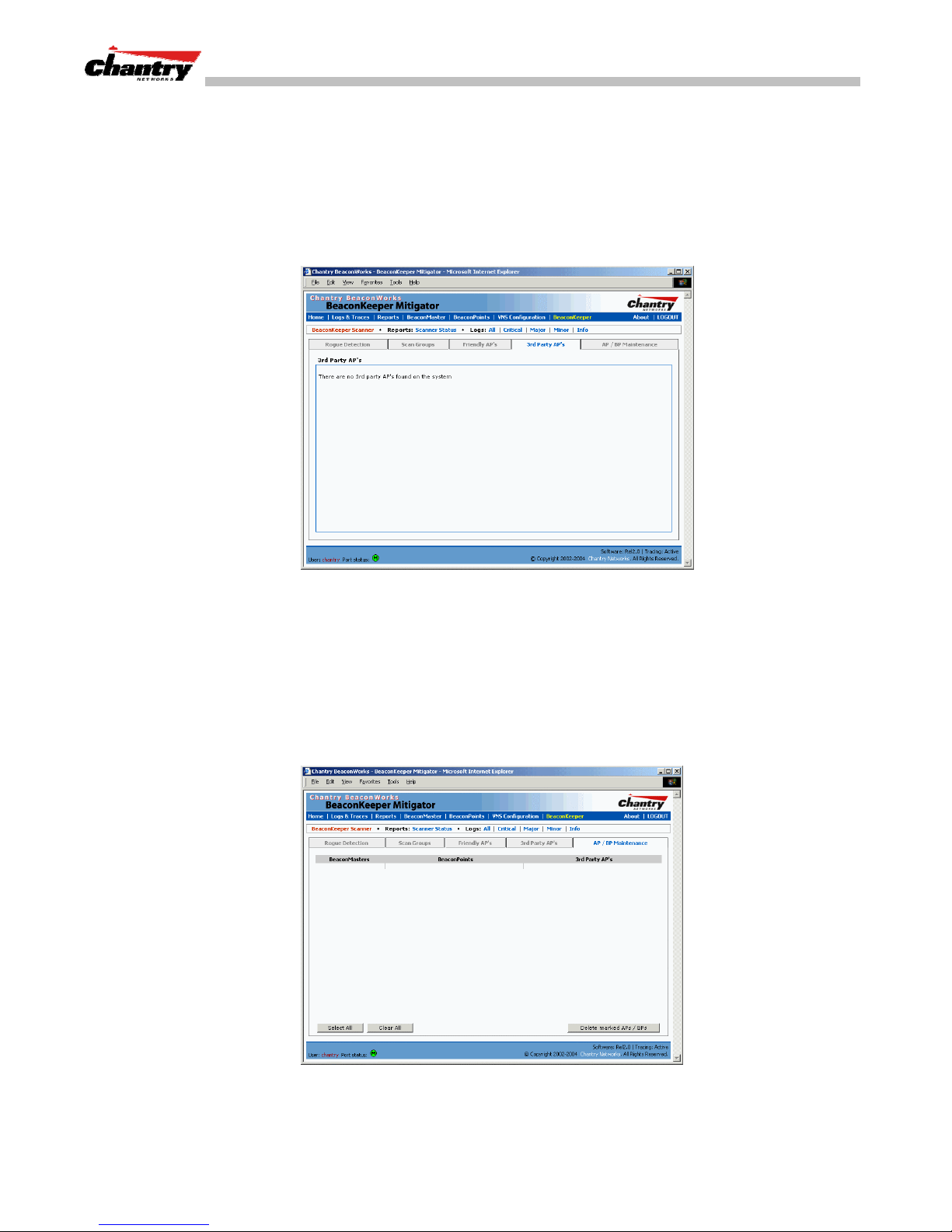
BeaconWorks User Guide – BeaconKeeper Mitigator: Detecting Rogue Access Points
7. To delete an access point from the list, highlight it and click on the
Delete
8. To modify an access point in the list, highlight it and make the appropriate
Save
changes in the entry fields. Click on the
View the BeaconKeeper list of Third-Party APs
To view the list of the known third-party access points, click on the
tab. The
3rd Party APs
screen appears.
button.
3rd Party APs
button.
Screen 62: BeaconKeeper Mitigator Scanner – 3rd Party APs
Maintain the BeaconKeeper list of access points and BeaconPoints
When BeaconPoints or Third-Party Access Points are deleted in the BeaconWorks
user interface on a BeaconMaster has its RFDC running and is in communication with
the Analysis Engine, this information will also be displayed in the BeaconKeeper
Mitigator’s
1. To view the
AP / BP Maintenance
AP / BP Maintenance
screen.
screen, click on the
AP / BP Maintenance
tab..
The deleted access points and BeaconPoints will be marked with a “Deleted” flag
Chantry Networks Inc. Copyright 2004. All rights reserved. BeaconWorks Rel 2.0 (051304) Page 99 of 134
Screen 63: BeaconKeeper Mitigator Scanner – AP / BP Maintenance
Page 100
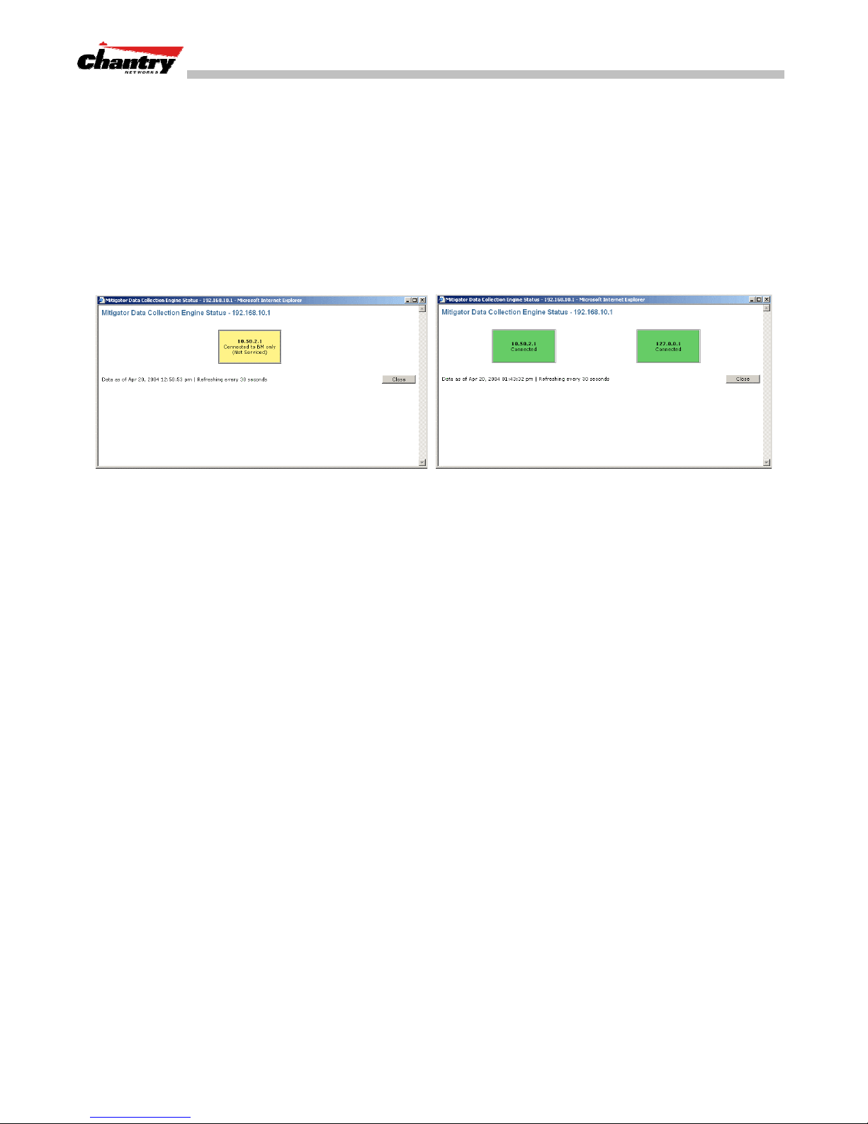
BeaconWorks User Guide – BeaconKeeper Mitigator: Detecting Rogue Access Points
2. To delete the marked access points and BeaconPoints from the BeaconKeeper
Mitigator’s database, click on the
BeaconKeeper Mitigator: Viewing the Scanner Status Report
Delete marked AP / BPs
When the BeaconKeeper Mitigator is enabled, you can view a report on the
connection status of the RF Data Collector Engines with the Analysis Engine.
View the BeaconKeeper scanner engine status display
button.
1. Click the
BeaconKeeper
tab in any screen, and then click on the
Scanner Status
tab. Examples of the connection reports are shown below.
Screen 64: BeaconKeeper Mitigator – Scanner Status Report
The IP address of the RFDC engine is displayed, with its status:
• Connected (green box) – the Analysis Engine has connection with the RFDC on
that BeaconMaster.
• Connected but not serviced (yellow box) – the Analysis Engine has connection
with the RFDC but is not synchronized with it yet.
• Not connected (red box) – the Analysis Engine is aware of the RFDC and
attempting connection.
Chantry Networks Inc. Copyright 2004. All rights reserved. BeaconWorks Rel 2.0 (051304) Page 100 of 134
 Loading...