

Page 1

ST-C5IDS
CAT5 Intercom Door Strike Relay Module
8
Page 2

The ST-C5IDS is a relay module that provides a contact closure whenever
it is activated by the Channel Vision CAT5 Intercom System. The contact
closure can be used to activate an electronic door strike mechanism or
gate opener. This allows the homeowner to answer the door from any
intercom station in the house and gives them the ability to unlock the door
or open the gate with the press of a button.
Features:
!
Compatible with Channel Vision CAT5 intercom system
!
Relay settings for N.O. and N.C. Operation
!
Variable relay times
!
Screw terminal and 110 connectors
!
LED indicator for easy troubleshooting
!
Mounts in a single-gang box
Screw Terminals
Signal, Ground, & Power
110 Connectors
Connections are parallel
(there is no “In” or “Out”)
LED Indicator
Flashes momentarily when
activation signal is received
ST-C5IDS
(Rear View)
S G P
Dip Switches
(see next page)
Programming Chart
(see next page)
Relay Contacts
2
Page 3

Setting the Dip Switches
There are four dip switches on the ST-C5IDS that allow you to set the
duration of the relay’s operation. Use the programming chart shown
next to the switches as a guide to help you choose the best setting for
your application. Note that the settings are labeled in pairs, such as
“On 8” and “Off 8.” If you choose the “On 8” setting, the relay will be
Normally Open (N.O.), and then it will close for 8 seconds when the
relay is activated by the intercom system. If you choose the “Off 8”
setting, the relay will be Normally Closed (N.C.) And then it will open
for 8 seconds when the relay is activated by the intercom system.
Dip Switches - Test Position
By default, the dip switches
are all in the down position.
This is the test position which
will cause the relay to operate
any time the door station call
button is pressed.
Set the switches to the desired
positions for normal operation.
Match the dip switches on the right to the desired setting as shown in
the programming chart on the left.
There are four possible strike durations:
8 seconds
20 seconds
90 seconds
200 seconds
3
Page 4

Wiring Configuration (Option A)
The ST-C5IDS can be connected to the CAT5 Intercom System in two
different ways. The diagram below shows the most typical
configuration in which the ST-C5IDS is installed in-line between the
Intercom Hub (P-0930) and the door station (DP-xxxxC). When the
button is pressed on the DP-xxxxC the ST-2000 Intercom Stations will
generate a door chime. Pressing Answer/End will open communication
with the DP-xxxxC. To activate the ST-C5IDS, press and hold the
direct call button that corresponds to the DP-xxxxC. (Please note that
the ST-C5IDS is also compatible with the IU-xxxxC which is not shown
in the this manual.)
DP-xxxxC
(Rear View)
S G P
500ft.
max
ST-2000
Page
Monitor
DND Answer/End
Press and hold
to activate
Room 1
ST-C5IDS
Room 2
Room 3
Room 4
Room 5
Room 6
Press here to
answer door
ST-C5IDS
P-0930
(Rear View)
Hub
S G P
Strike
Power
Supply
Link
In
A
B
C
D
Page Trigger
Page Out
Room 1 Room 2
Model
P-0930
Room 3
CH ANN EL
CH ANN EL
VI SIO N
VI SIO N
PRO
IR
Emitters
Room 5
Room 4
Whole-House Intercom
TM
TM
Room 6
+15VDC
Link
Out
Power
Door Strike
4
(NOT SOLD BY CHANNEL VISION)
Mechanism
Page 5

Wiring Configuration (Option B)
The diagram below shows another valid wiring configuration in which
CAT5 wire runs directly to the door station (DP-xxxxC) from the Intercom
Hub (P-0930). A separate 3-conductor wire is then used to connect the
ST-C5IDS to the DP-xxxxC using the screw terminals for Signal, Ground,
and Power. When the button is pressed on the DP-xxxxC the ST-2000
Intercom Stations will generate a door chime. Pressing Answer/End will
open communication with the DP-xxxxC. To activate the ST-C5IDS, press
and hold the direct call button that corresponds to the DP-xxxxC.
350ft.
max
DP-xxxxC
(Rear View)
S G P
ST-C5IDS
(Rear View)
S G P
500ft.
max
A
B
C
Link
D
In
Page Trigger
Hub
Room 1 Room 2
Page Out
Monitor
DND Answer/End
Model
P-0930
ST-2000
Page
P-0930
Room 4
Room 3
CH ANN EL
CH ANN EL
TM
TM
VI SIO N
VI SIO N
PRO
IR
Emitters
Press and hold
to activate
Room 1
ST-C5IDS
Room 2
Room 3
Room 4
Room 5
Room 6
Room 5
Room 6
Whole-House Intercom
+15VDC
Press here to
answer door
Link
Out
Power
Strike
Power
Supply
Door Strike
Mechanism
(NOT SOLD BY CHANNEL VISION)
5
Page 6

Troubleshooting
1. The electronic door strike or gate opener, closes when it’s
supposed to be open and opens when it is supposed to be closed.
If the operation of the system is the opposite of what is needed, then
you may have selected a Normally Closed (N.C) relay setting when you
should have selected a Normally Open (N.O.) relay setting. Review the
“Setting the Dip Switches” section of this manual for more details.
2. The gate opener only operates for a short period of time (the gate
only opens half way and then begins to close).
Some gate openers require the activation contact to be closed for the
entire time it takes the gate to open. If the strike duration setting is too
short the gate may not open completely. Using the dip switches, select
a longer time period for the relay to operate. Review the “Setting the
Dip Switches” section of this manual for more details.
3. The electronic door strike or gate opener does not respond to
commands to open.
A) Check the LED on the back side of the ST-C5IDS to make sure that
it is receiving a signal from the intercom system. If the LED does
not light, double check the wiring between the ST-C5IDS and the
intercom system.
B) If the LED on the back side of the ST-C5IDS is lighting up, but door
strike or gate opener is not responding try bypassing the ST-C5IDS
module. To do this, remove the wires from the relay contacts and
try touching them together momentarily. If this triggers the opener
system to operate there may be a problem with the ST-C5IDS.
Please contact Channel Vision Tech support for assistance. If the
opener system does not operate when the ST-C5IDS is bypassed,
please contact the manufacturer of the door strike or gate opener
for assistance.
Specifications: (typical @25º C)
Operating Voltage : 12VDC
Max Current Through Relay: 10 Amps
Cable requirements: CAT5 or 3-conductor 18-24AWG
Specifications subject to change without notice.
6
Page 7
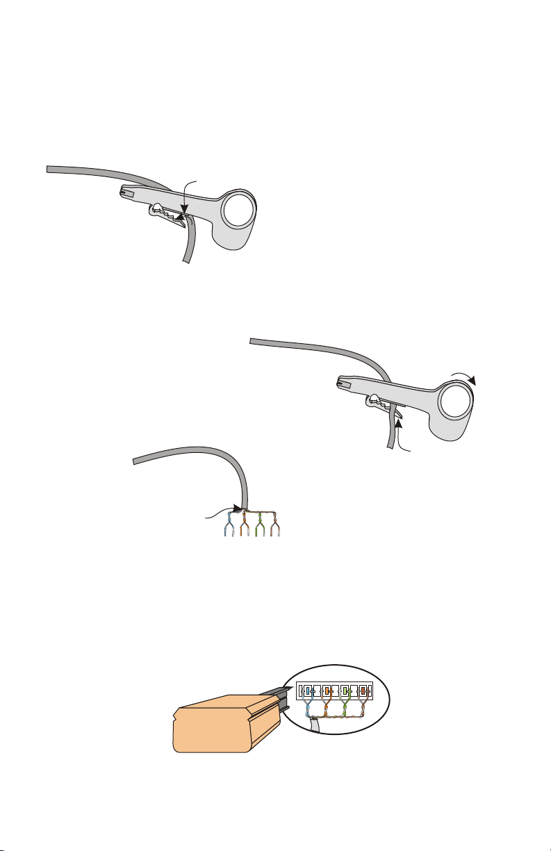
Stripping and Connecting CAT5 Wire
CAT5 cable should be stripped with a proper stripping tool, such as Channel
Vision’s J-110 tool.
1. Place the CAT5 between the blade and the first notch of the J-110 tool.
Cat5
3. Inspect the inner wires for damage.
If any wires are cut start over at step 1.
Check for damage
4. Use any standard 110 punch-down tool to properly seat all wires.
Note: Do NOT use a screwdriver or any other tool that is not specifically
designed for terminating UTP cable. Using improper tools will damage
the connector!
Blade
2. Rotate the tool only once around the CAT5. Multiple
turns will cause you to cut into the inner wires.
Rotate
1 turn only
Slight
pressure
7
Page 8

Channel Vision Technology will repair or replace any defect in
material or workmanship which occurs during normal use of this
product with new or rebuilt parts, free of charge in the USA, for two
years from the date of original purchase. This is a no hassle warranty
with no mail in warranty card needed. This warranty does not cover
damages in shipment, failures caused by other products not supplied
by Channel Vision Technology, or failures due to accident, misuse,
abuse, or alteration of the equipment. This warranty is extended only
to the original purchaser, and a purchase receipt, invoice, or other
proof of original purchase date will be required before warranty
repairs are provided.
Mail in service can be obtained during the warranty period by calling
(800) 840-0288 toll free. A Return Authorization number must be
obtained in advance and can be marked on the outside of the shipping
carton.
This warranty gives you specific legal rights and you may have other
rights (which vary from state to state). If a problem with this product
develops during or after the warranty period, please contact Channel
Vision Technology, your dealer or any factory-authorized service
center.
w ww .c ha nn el vi si on .c om
234 Fischer Avenue, Costa Mesa, California 92626 USA
(714)424-6500 (800)840-0288 (714)424-6510 fax
email: techsupport@channelvision.com
500-180 revC
 Loading...