

Channel Vision SIK-XXXXA-XX, SIK-XXXXC-XX, SIK-XXXXP-XX, SIK-XXXXI-XX, SIK-XXXXSK-XX Instruction Manual

SIK
SIK-XXXXC-XX
SIK-XXXXP-XX
SIK-XXXXI-XX
SIK-XXXXSK-XX
-XXXXA-XX
Elite Telephone Entry Door Intercom
1 / 2
2 / 3
4 / 5
6 / 7
9 / 0
Channel Vision’s SIK-Series door stations can interface with a
variety of telephone entry control products to provide
communication with the front door. They are available in a
variety of configurations including options for an IP or 960H
analog camera and compatibility with Panasonic’s popular KSU
phone systems. A contact closure is provided for connection to
a door strike relay or door strike.
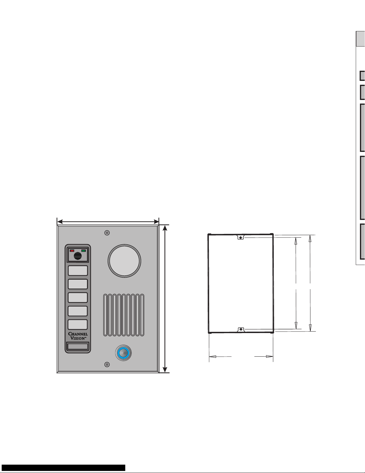
Dimensions: Plate
6.70”
9.70”
8.350” 8.79”
5.84”
0.25”
Plate
Depth
Only
Dimensions: SIK-Rbox
(not included)
Features:
h
h
IP or 960H analog camera
h
h
h
h
Rust-resistant faceplate
Discrete speaker and microphone
Flush or surface mount options
Available in many different finishes
Lit button
1 / 2
2 / 3
4 / 5
6 / 7
9 / 0
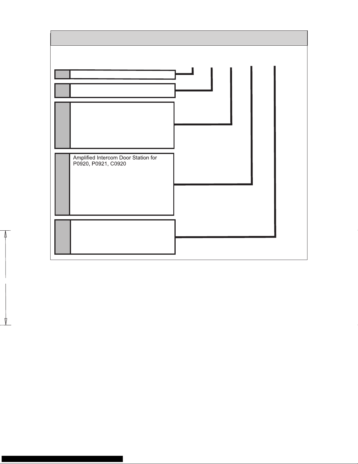
Understanding the model number:
Understanding the compatibility options
Part numbering: SIK door plates
There are three different types of systems that SIK door stations can
be used with. The compatibility for these different types of systems is
indicated by the suffix of the model number which follows the 4-digit
numerical code.
If the suffix is the letter “A”, such as SIK-6212A, that door station is
compatible with Channel Vision’s telephone entry products including
models P-0920 & P-0921.
If the suffix is the letter “C”, such as SIK-7212C, then the door plate is
compatible with Channel Vision’s Whole-House CAT5 Intercom Hub,
model P-0930.
If the suffix is the letter “P”, such as SIK-7212P, then the door plate is
compatible with Panasonic KSUs.
Please double check to be sure that you have purchased the correct
model number for your application.
2
Analog Camera
Megapixel IP Camera
Wiegand 26 Bit Nickel Keypad
Wiegand 26 Bit Black Keypad
Single Door Black Keypad
Single Door Nickel Keypad
SIK Elite Series Faceplate
6
7
SIK
A
Part Number Example:
Oil Rubbed Bronze
Black
Satin Nickel
White**
Polished Brass**
Antique Brass**
252
282
302
212
222
232
P
C
I
SK
Compatible with Panasonic KSU’s
P0930 CAT5 Controller
IP Camera with 2 Way Communication
Door Station
Intercom Door Station with SIP Kit
WN
WB
SB
SN
Understanding the model number:
Understanding the compatibility options
Part numbering: SIK door plates
There are three different types of systems that SIK door stations can
be used with. The compatibility for these different types of systems is
indicated by the suffix of the model number which follows the 4-digit
numerical code.
If the suffix is the letter “A”, such as SIK-6212A, that door station is
compatible with Channel Vision’s telephone entry products including
models P-0920 & P-0921.
If the suffix is the letter “C”, such as SIK-7212C, then the door plate is
compatible with Channel Vision’s Whole-House CAT5 Intercom Hub,
model P-0930.
If the suffix is the letter “P”, such as SIK-7212P, then the door plate is
compatible with Panasonic KSUs.
Please double check to be sure that you have purchased the correct
model number for your application.
3
SIK 7 252 A-WN
Analog Camera
Megapixel IP Camera
Wiegand 26 Bit Nickel Keypad
Wiegand 26 Bit Black Keypad
Single Door Black Keypad
Single Door Nickel Keypad
SIK Elite Series Faceplate
6
7
SIK
A
Part Number Example:
Oil Rubbed Bronze
Black
Satin Nickel
White**
Polished Brass**
Antique Brass**
252
282
302
212
222
232
P
C
I
SK
Compatible with Panasonic KSU’s
P0930 CAT5 Controller
IP Camera with 2 Way Communication
Door Station
Intercom Door Station with SIP Kit
[
[
[
[
[
WN
WB
SB
SN
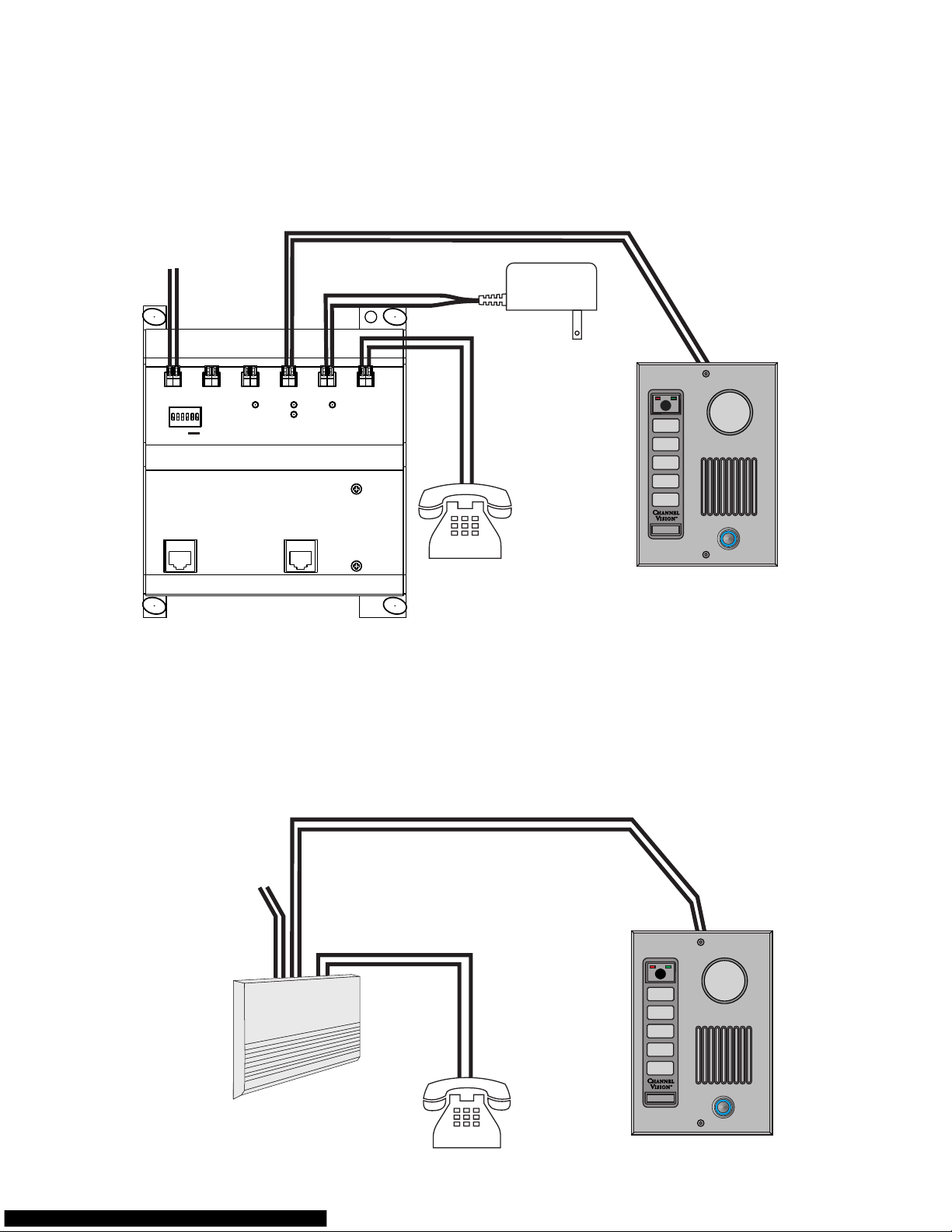
The SIK SIK both interface with the Channel Vision
telephone entry controllers, P-0920 and P-0921 to provide audio and video
communication with the front door. Using a 2-conductor wire, connect the Telephone
Entry Controller to the empty screw terminal block on the door station (see diagram).
For the camera, use CAT5 (POE for power) or a coax for analog video and 18/2 wire
-6xxxA-xx and -7xxxA-xx ’s
Channel Vision Compatible (SIK-xxxxA-xx)
Panasonic (SIK-xxxxP-xx) Compatible
Strike
Active
Ring
Intercom
Active
12VAC
#
or
*
No CO
Strike
Time
3/5 rng
1
2
3
PowerIntercomUnlock
Door
ChimeCO Input
Phones
TELEPHONE ENTRY CONTROLLER
CO Input
Telephones
Model
P-0920
PRO
CH AN NEL
TM
VI SI ON
From Telephone
Service Provider
House
Telephones
12VAC
500mA
Using a 2-conductor wire, connect the door
phone output of your Panasonic KSU to the
empty screw terminal block on the door station
Channel Vision's Panasonic models are a compatible replacement for the Panasonic
KXT30865. They are an attractive alternative to the standard plastic door station sold
by Panasonic. This product interfaces with Panasonic’s KSU phone systems to
provide communication with the front door.
Connect to the
terminals marked
“TO SYS”
From Telephone
Service Provider
System Phones
Panasonic
KSU
4
1 / 2
2 / 3
4 / 5
6 / 7
9 / 0
1 / 2
2 / 3
4 / 5
6 / 7
9 / 0
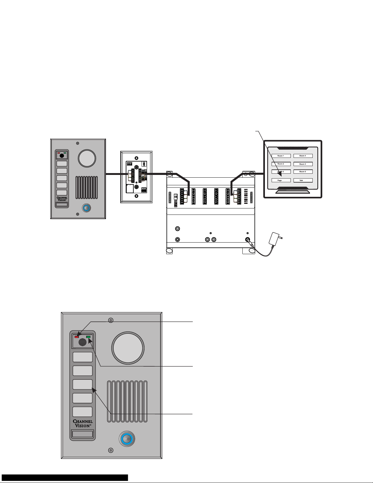
The diagram below shows how to connect the SIK-xxxxC-xx to Channel
Vision’s CAT5 Whole-House Intercom system. When the button is pressed on
the SIK-xxxxC-xx the ST-3000 Intercom Stations will generate a door chime.
Pressing Answer/End will open communication with the SIK-xxxxC-xx. Model
SIK-6xxxC-xx includes an analog 960H color camera and SIK-7xxxC-xx
includes an IP camera.
Channel Vision Compatible
Using CAT5 wire, connect the
P-0930 to the 110 connector
on the door station
SIK-xxxxC
SIK-7xxxA
SIK-7xxxP
1 / 2
2 / 3
4 / 5
6 / 7
9 / 0
1 / 2
2 / 3
4 / 5
6 / 7
9 / 0
5
ST-C5IDS
S G P
500ft.
max
The diagram below shows how to connect the SIK-xxxxC-xx to Channel
Vision’s CAT5 Whole-House Intercom system. When the button is pressed on
the SIK-xxxxC-xx the ST-3000 Intercom Stations will generate a door chime.
Pressing Answer/End will open communication with the SIK-xxxxC-xx. Model
SIK-6xxxC-xx includes an analog 960H color camera and SIK-7xxxC-xx
includes an IP camera.
Channel Vision Compatible
( -xxxx )
CAT5 Intercom
SIK C-xx
P-0930
PRO
CH ANN EL
TM
VI SIO N
Model
P-0930
Whole-House Intercom
Page Out
Page Trigger
IR
Emitters
+15VDC
Power
Link
In
Link
Out
Hub
A
B
C
D
Room 1 Room 2
Room 3
Room 4 Room 5
Room 6
ST-3000
Press here to
answer door
Using CAT5 wire, connect the
P-0930 to the 110 connector
on the door station
SIK-xxxxC
1 / 2
2 / 3
4 / 5
6 / 7
9 / 0
Using the Access Keypad
Power Light: (Green)
IMPORTANT: if power
light does not illuminate,
immediately disconnect
power supply and check
for correct polarity.
Status Light: (Red)
Keypad
1 / 2
2 / 3
4 / 5
6 / 7
9 / 0

SIK Series Keypad Programming
The SIK Series Keypad is an easy to program, easy to use, stand alone, selfcontained entry system with features suitable for basic access control
requirements. Providing either a voltage output or dry contact closure, the SIK
Series Keypad is designed to control any fail-safe or fail-secure electric locking
device. One relay output is available to provide a variety of access control
configurations including single door access control, Gate/Garage Door control.
Overview of System Code Programming
There are two levels of codes for the SIK Series Keypad.
1. The Master Code: Used by the owner to program User Codes.
2. User Codes: Used by guests/personnel to open the door.
Important Notes:
1. The Keypad has two digits on each pad. The system reads these numbers as
the same. For example: “1-3-5-7-9” is the same as “2-4-6-8-0”.
2. All codes must be 3 to 8 digits.
3. All codes must be different from each other.
4. Do not program codes, which are part of other codes.
Example: User Code 1: “1-2-3-4” and User Code 2: “1-2-3”
5. During programming, the system resets after 5 seconds if a number is not
entered. Do not let more than 5 seconds elapse between entries or the system
will reset and you will have to start over.
Overview of the Master Code:
Knowledge of the Master Code is the highest priviledge granted to a user of the
SIK Series Keypad system. There is only one master code, which is used to
program each of the 5 User Codes.
The factory default Master Code, “1-3-5-7-9”, can be used for initial
programming but should be changed to a unique code.
Note: The Master Code does not have the ability to Latch.
Programming or changing the Master Code:
1. Select a 3 to 8 digit code that will be used for the Master Code.
2. Enter the old Master Code (default is “1-3-5-7-9”) followed by the symbol on
the keypad. (The Keypad will beep rapidly 4 times*) Proceed to step 5.
3. If you do not know the Master Code, locate the PINK Program wire on the
harness. (As an alternative, you can momentarily short the two “PGM” pins on
the back of the Keypad. This will take you to step 5)
4. Touch the PINK Program wire to the BLACK wire for one second (The Keypad
will beep rapidly 4 times)*
5. At the Keypad, enter “1-1-1-9” to open the memory (you will hear three rapid
beeps) and immediately enter your new Master code.
(Do NOT let more than five seconds elapse between entries or the system will
reset and you will have to start over.)
6. After entering your new Master Code, wait five seconds for the 3 reset beeps.
* Once in Programming Mode, you have 2 minutes to begin programming.
After 2 minutes, the system resets to Normal operation.
6
3. If you do not know the Master Code, locate the PINK Program wire on the
harness. (As an alternative, you can momentarily short the two “PGM” pins on
the back of the Keypad. This will take you to step 5)
4. Touch the PINK Program wire to the BLACK wire for one second (The Keypad
will beep rapidly 4 times)*
5. At the Keypad, enter “1-1-1-7” to open the memory (you will hear three rapid
beeps) and enter a combination of “5’s” (for every five second increment) and
“1’s” (for every one second increment) that equal your desired Door Open Time.
Each valid key press (a “1” or a “5”) will generate a double beep.
Example: “1-1-1-7 5-5-5-1-1” 17 seconds
6. After entering your Door Open Time, wait five seconds for the 3 reset beeps.
Notes: * Once in Programming Mode, you have 2 minutes to begin programming.
You will hear a double beep with each valid key press. Once you begin entering
the combination of 1’s and 5’s do not let more than five seconds elapse between
entries or the system will reset. Maximum Door Open Time is 120 seconds.
Overview of User Codes:
There are a total of 5 User codes that can be programmed into the SIK Series
Keypad. User Codes can vary in length from 3 to 8 digits. Each User Code is
programmed into one of 5 User Locations. These Locations are as follows:
User # User Location
User Code 1 1-1-1
User Code 2 1-1-3
User Code 3 1-1-5
User Code 4 1-1-7
User Code 5 1-1-9
Once a User Code has been programmed into a User Location, the User Code
can be easily changed or deleted from the system
Programming User Codes:
To Program a New User Code/Change an Existing User Code:
1. Choose a new 3 to 8 digit code that will be used for this User Code.
2. Decide which User Location to place this User Code
3. Enter the Master Code, followed by the User Location (you will hear three
rapid beeps) and immediately enter the new User Code. (Do not let more than
five seconds elapse between entries or the system will reset)
Example: “1-3-5-7-9 1-1-1 1-3-3-5”
This programs the code 1-3-3-5 into User Location #1.
4. After entering your new code, wait five seconds for the 3 reset beeps.
To Delete a User Code:
1. Enter the Master Code, followed by the User Location of the User Code you
want to delete (you will hear three beeps).
Example: “1-3-5-7-9 1-1-5” This deletes the User Location #3 programmed
code.
SIK Series Keypad Programming Cont.
 Loading...