

Page 1

oldHoldH
Ad u
Ad u
EN
CER
3
3
C era 4
C era 4
am
am
C
C
H
H
AN NEL
AN NEL
VI S
VI S
I
I
O
O
PR
3
ut 4p O
ut 4p O
Loo
Loo
VideoVideo
Audio
Aud
r
a 3ame
a 3amerC
C
meraCa 4
meraCa 4
N
N
O
io
RS-232RS-232
MT
MT
1
itor
Mo
itor 1n
Mo
n
IR o
M n 1)
In (
IR o
M n 1)
In (
ut 2
(Mon)
IR O
ut 2
(Mon)
IR O
w
wPo
Po
2
o
2M nitor
o
M nitor
CA
Ca
Ca
m
m
era 1
era 1
L
T
5 C M A
A
Ca
Ca
m
m
O t 1
uoop
O t 1L
uoop
ame 1C ra
ame 1C ra
ER
V o e
V o e
ide
ide
era 2
era 2
Mo
P-6 140
oop Ot 2Luoop Ot 2L
Cam
Tm j st
Tm j st
i e
i e
SE
QU
Pr
Pr
sent
sent
C mera
C mera
a
a
d
e
l
u
Loop Out 3Loop Out
pInutspInuts
e
ra 2
ra 2eCam
P-6014
CAT5 Camera Sequencer
6210
er
er
Color CAT5 Camera
PRO
PRO
8
Page 2
The P-6014 is a 4 input 2 output camera sequencer and switcher for Channel
Vision’s 6210 color CAT5 cameras (sold separately). Easily view any of the
cameras simply by letting them sequence through the screen automatically or
by pressing a button on the optional remote control. The RS-232 interface as
well as audio/video loop out connections make it easy to integrate the P-6014
into any security system - from basic to the most complex.
P-6014 Features:
!
Creates an easy interface for CAT5 cameras
!
Switches both audio and video
!
Monitor output sequences through the camera views automatically
!
IR and Serial Control options
!
Mounts in a structured wire enclosure
!
Cost effective and easy to install
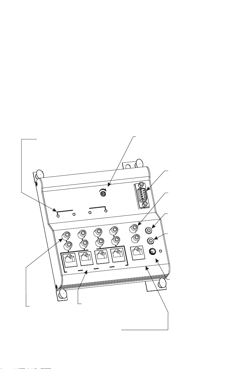
Video Present...
LED indicators light when video
signal is detected.
Loop Out...
Provides
Audio/Video output
from each camera
2
A
C
Camera 1Camera 1
C MER
5 A
T
Out 1
Out 1
o p
o p
L o
L o
Hold
Hold
t
t
sT
s
ju
ju
ime Ad
ime Ad
T
QU C
E EN ER
A S
e
e
s nt
s nt
i
i
V deo Pre
Ca
Ca
meCa ra
me
Ca ra
V deo Pre
r 2
r 2me a
me a
L
Camera
l
e
d
o
M
6 14P- 0
t 2
t 2
OuL
Ou
oop
oop
1
1
In u
In up ts
ra
ra
o p
o p
L
L
p ts
2 Came
2
Came
3Camera
3
o Out 3
o Out 3
meraa 4
meraa 4
C
C
me
me
Ca ra 3
Ca ra 3
p Ou
p Ou
Loo
Loo
EL
EL
NN
NN
A
A
H
H
C
C
TM
TM
N
N
O
O
I
I
S
S
VI
VI
PRO
t 4
t 4
ed o
e
d o
i
i
V
V
dio
dio
Au
Au
4Ca
mera 4Ca
mera
Inputs...
Connect CAT5 cameras here
Monitor 2...
Connect 3112 here to provide a secondary
monitor output, independent from Monitor 1
Time Adjust... Changes the time
period the cameras are viewed
before switching. The maximum
setting will stop cycle mode and
show the current camera.
RS-232...
Connect serial
controller here
Monitor 1...
Connect audio/video
monitor here
IR In (Mon 1)...
Connect an IR receiver
1
1
or an IR system
IR Out (Mon 2)...
2)
2)
Monito
2
2
RS-23
RS-23
r 1
r 1Monito
n )IR In
n )IR In
o
o
(M
(M
Out (Mon
Out (Mon
IR
IR
Outputs IR signals
received via the 3112
connected to Monitor 2
r
r
we
we
Po
Po
n r 2Mo ito
n r 2Mo ito
Power...
Connect power
supply here
Page 3
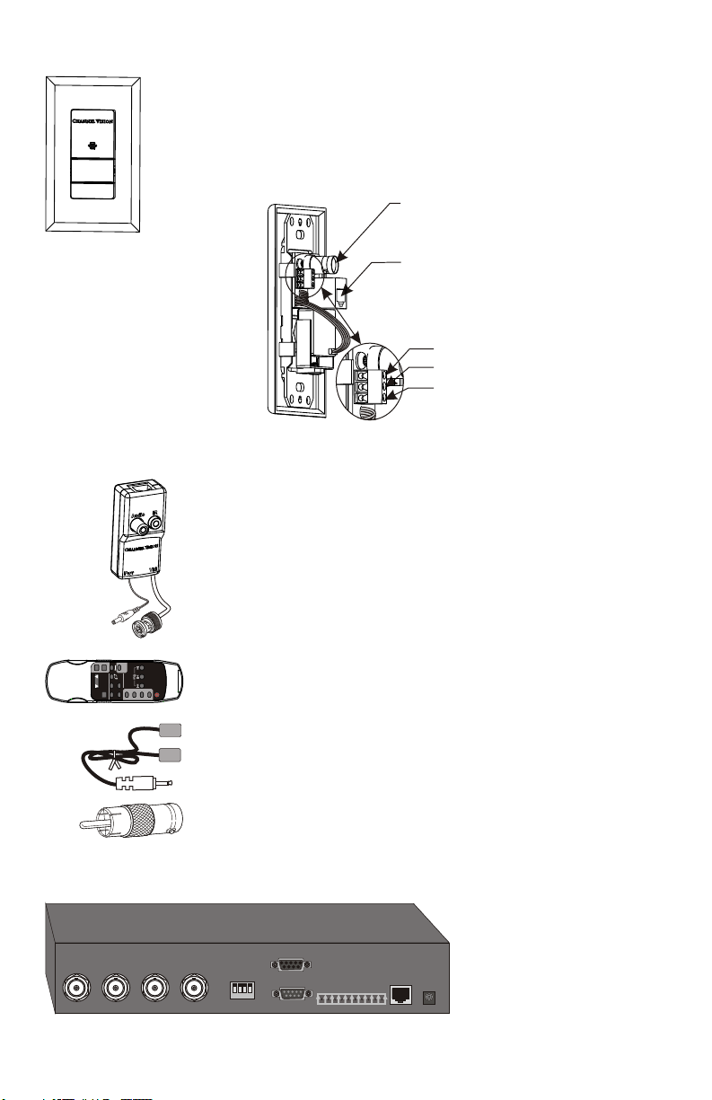
The 6210 Color CAT5 camera with audio mounts in a single
gang J-box or low-voltage ring and is designed to be
connected directly to the P-6014 camera inputs. The P-6014
provides loop out connections that allow the camera signals
to be connected to another device such as a DVR or
modulator.
6210 Features:
!
BNC & CAT5 output
!
Built-in microphone
!
Screwless trim plate
!
Mounts in a 1-gang box
!
Easy to install
Accessories (Sold Separately)
3112 ... CAT5 audio/video interface. Allows audio,
video, power, and IR signals to be connected to the
CAT5 cable. It can be used to transform a traditional
camera into a CAT5 camera, or used to extract audio
and video from the Monitor 2 output of the P-6014.
When used on the Monitor 2 output, the IR input jack
can be used to input IR signals that allow Monitor 2 to
select different camera views than Monitor 1.
BNC Video Output...
Connect coax here to use
as a conventional camera
RJ-45 Output...
Connect CAT5 here to use
with P-6014
Camera Power & Audio Out...
Audio out from microphone
Ground (shared)
+12VDC
MODEL
POWER
ZONE
CATV
A0505
MOD
VOL
MUTE
CHANN EL V ISI ON
CAMERA
1
3
O
URC
E
S
2
4
4
A0505 ... Remote control. Contains IR codes for
POWER
controlling the P-6014 as well as many other Channel
123
Vision audio/video products.
IR-3001 & IR-3002 ... Single and dual head IR flashers.
Use one head per source to control from the remote
room. (IR-3002 shown).
2129 ... RCA to BNC adaptor. Use to adapt video
signals on BNC cables (such as cameras) to the RCA
video input commonly found on TVs and monitors.
Complementary Product (Sold Separately)
W4000 ... Web Camera
Server allows any 4
camera video signals to
be viewed through the
12VDC12VDC
local network or internet
on any computer.
Camera 1Camera 1 Camera 2Camera 2 Camera 3Camera 3 Camera 4Camera 4
11
33
22
11
75 ohm75 ohm
com 2com 2
com 1com 1
44
GPIOGPIO
EthernetEthernet
3
Page 4

P-6014 Camera Sequencer Basic Application...
The primary function of the P-6014 is to sequence through its 4 camera inputs.
The Time Adjust control determines the length of time each camera view is
shown before switching to the next camera view. Unless the RS-232 or IR
remote control features are used, the P-6014 will remain in the Auto Cycle
mode. If only three of the four inputs have an active video signal, only the three
active camera inputs will be shown when in the Auto Cycle mode.
The 6210 camera was specifically designed to work together with the P-6014.
A single CAT5 cable provides power to the camera and delivers video and
audio signals back to the sequencer. These audio/video signals are output
through the monitor connections on the P-6014.
TV (Monitor)
6210
P-6014
HoldHold
sti e Adj
sti e Adj
uT
u
m
m
T
EQUENC R
am
am
C era
ERA S
AM
T5
A C EC
i resentVdeo P
L
L
oop Ou
oop Ou
i resentVdeo P
2Camera
2
Camera
1C era
1
o e
6
-
P
p O
p O
Loo
1
1
t
t
a 1
a 1
r
r
me
me
Ca
Ca
a
a
C mera 4
C mera 4
Camera 3Camera 3
l M d
4
1
0
Loop Out 3Loop Out 3
ut 2Loo
ut 2
uts
utsInp
Inp
2
2
Camera
Camera
Camer
Camer
N
N
AN
AN
H
H
C E
C E
O
O
I
I
IS
IS
R
V
V
P
ut 4
ut 4
p O
p O
Loo
Loo
d
dV
i eo
i eo
V
Audio
Audio
e
e
Cam ra
Cam ra
3
3
a
a
2
2
S
S
R -23
R -23
L
L
TM
TM
O
N
N
r 1
r 1
n 1)
n 1)
Monito
Monito
R I Mo
I n (R I Mo
I n (
on 2)
on 2)
t (M
t (M
Ou
Ou
IR
IR
er
PowerPow
2
2
t
t
i or
i or
Mon
Mon
4
4
Max CAT5 length between
3112 and 6210 is 250ft.
6210
6210
3112
6125
The P-6014 can be used with Channel Vision’s 6210 CAT5 camera or any
conventional camera when used with the 3112 accessory. The 3112 has
multiple applications, but when used in this application the IR connection will
not be used and the Audio connection would only be used if your conventional
camera has a built-in microphone.
4
Page 5

Using The A0505 Remote Control... P-6014 Camera Sequencer
The A0505 is designed to allow you to control the switching functions on your
P-6014. The A0505 allows you to choose any of the 4 cameras or select the
Auto Cycle mode.
P-6014
6210
ol
ol
H d
H d
me dj
i A ustme dj
i A ust
T
T
ER
C
Q EN
SE
U
A
ER
CA
amera
amera
M
CA
T5
C
C
Lo
Lo
resent
resent
o P
o P
deV
deV
i
i
Ca
Camera 2
Camera 2
1
1
l
de
Mo
4
1
0
-
P 6
Out 2
Out 2
L op
o
o
L op
t 1
t 1
O
O
p u
p u
o
o
Ca r
Ca r
1aC mera
1a
C mera
mera 3Ca
mera 3
me a
Lo p u
Lo p u
I unp tsI unp ts
ra 4
ra 4
Came
Came
3o O
3
t
t
o O
Ca
Ca
2me a
2
EL
EL
NN
NN
A
A
H
H
C
C
VI SIO
VI SIO
PR
O t 4
O t 4
p u
p u
o
o
Lo
Lo
d
Vi eo
Vi eod
Au
mera
mera
Ca
Ca
a
a
r 3me
r 3
me
N
N
TM
TM
O
4
4
Monitor 1Monitor 1
iodAu
iod
-232RS-232
RS
)
)
1IR
1
on
on
M
M
(
(
In
In
IR
2)
2)
t (Mon
t (Mon
IR Ou
IR Ou
r
r
Powe
Powe
nitoro 2
nitoro 2
M
M
Note: Only one
camera connection is
shown in this diagram,
but the P-6014 can
IR-2400
support up to 4 CAT5
cameras.
Remote Control Key:
CAMERA
1
3
2
4
I
POWER
NNEL V IS ON
1
H
C A
2
S
L
O
E
U
OD
5
0A05
M
R
3
C
E
4
2
1
4
A
ER
M
A
E
C
3
O
Z N
POWER
UTE
M
TV
CA
L
O
V
OD
M
Camera Next... Changes the Monitor output to the next
active camera in the sequence. If you are viewing camera 1,
pressing it once will show camera 2 and so on. Note: Any
unused camera inputs will be skipped.
Camera Cycle... Causes the Monitor output to sequence
through the cameras. The time adjustment on the P-6014 determines
how long each camera view is displayed before switching to the next one.
Note: Any unused camera inputs will be skipped.
1, 2, 3, 4 Camera Views... Changes the Monitor output directly to the
corresponding camera input.
5
Page 6

Controlling The P-6014 Through The Monitor 2 Connection...
Controlling the P-6014 through the IR Input connection will only affect the
Monitor 1 output. To control the Monitor 2 output, IR signals must come
through the Monitor 2 output RJ-45 connection via the 3112 as shown below.
6210
Note: Only one
camera is shown,
but the P-6014 can
support up to 4
CAT5 cameras.
Home Theater TV (Monitor 2)
Camera
A C
Loo t
Loo t
P-6014
M
A ERA
deo rese
deo rese
Vi
Vi
era 2
era 2
Cam
Cam
1Camera
1
M
oop O
oop O
L
L
1p
1
Ou
Ou
p
ra 1
ra 1
Came
Came
TV (Monitor 1)
ld
ld
Ho
Ho
djT m
dj
A ust
A ust
e
e
i
i
Tm
RC T5
CE
N
UE
SEQ
nt
nt
P
P
el
od
14
0
P-6
ut
ut
a 4
a 4a
mer
mer
a
C
C
3
3
era
era
am
am
C
C
t
t
op
op
Lo
Lo
2
2
Inputs
Inputs
a 2Ca
a 2Ca
r
r
me
me
N
N
A
A
H N
H N
C
C
I
I
V SION
V SION
PR
Ou 4
Ou 4
op
Lo top
Lo t
Ou 3
Ou 3
V
mer
mer
C
ra 3a e
ra 3a e
m
m
C
32
32
S-2
S-2
R
R
L
L
E
E
MT
MT
O
Mo
Mo
ideoV
ideo
oA
o
i
i
ud
ud
A
a 4Ca
a 4Ca
)
)
1
1
i o 1
n
n
nt ri o 1
nt r
R
R
I In (Mo
I In (Mo
o )
o )
(
(
ut M n 2
ut M n 2
R O
R O
I
I
IR-3200
wer
wer
Po
Po
nitor 2Mo
nitor 2
Mo
Connect an IR emitter
to the IR Output to
allow IR pass-through.
Max CAT5 length between
3112 and 6210 is 250ft.
3112
Audio In
Not used
IR-2400
Video In
2129
BNC to RCA adaptor
N
ON V
ISI
WER
O
P
CHAN EL
EL
OD
55
M
A00
In this diagram, when IR signals are received through the IR-2400
they are sent back to the P-6014 through the 3112. These IR
signals will only affect the Monitor 2 output. The Monitor 1 output
can be independently controlled by connecting an IR receiver to
the “IR Input” jack on the P-6014.
In this configuration, the P-6014 allows IR pass through so that IR signals
intended for other devices (such as a whole-house music system) will be
routed out the “IR Output” jack on the P-6014.
6
1
2
S
O
U
3
R
C
E
4
2
4
1
3
AMERA
C
E
N
ZO
E
WR
POE
UT
M
V
T
O
VL
CA
MOD
Page 7

RJ-45 Pin Out Diagram...
For troubleshooting purposes, it may be helpful to know the wire pin out for the
RJ-45 jacks on the P-6014. They are shown below:
RJ-45 Jack
(TIA 568A)
8 7 6 5 4 3 2 11
Camera Inputs
Signal
Pin
8
Gnd
7
Video
6
Gnd
5
N.C.
4
Gnd
3
Audio
2
Gnd
1
+12VDC
Monitor 2 Output
Signal
Pin
8
Gnd
7
Video
6
Gnd
5
IR
4
Gnd
3
Audio
2
Gnd
1
+12VDC
Controlling The P-6014 Through The RS-232 Port...
The RS-232 port is the most flexible way to control the P-6014 because it
provides access to every feature on the unit. This is the preferred way for most
high-end control system to interface with devices such as the P-6014.
Connect serial data controller
to the Serial port
(Hex codes on pages 8-11)
6210
TV (Monitor 1)
P-6014
CAMERA
T
CA 5
era 1
era 1
Cam
Cam
Ou
Ou
p
p
Loo
Loo
Note: Only one
camera is shown,
but the P-6014 can
support up to 4
CAT5 cameras.
Home Theater TV (Monitor 2)
t 1
t 1
Camera
Ca
mera 1Ca
mera 1
oop 2L
oop 2
L
old
old
H
H
ustTime Adj
ust
Time Adj
UENCER
Q
SE
entVideo Pre
sentVideo Pre
s
Cam
Cam
2Camera
2
l M d
o e
4
1
0
6
-
P
t
t
Ou
Ou
Camer
Camer
4mCa era
4m
Ca era
3
3
era
era
o O
o O
Lo p
uts
utsInp
Inp
a 2
a 2
NE
NE
AN
AN
H
H
C
C
ON
ON
I
I
S
S
I
I
R
V
V
P
t
top Ou 4
op Ou 4
Lo
Lo
3Lo p
3
ut
ut
C m ra
C m ra
i odeV
i ode
V
Camer
Camer
3
3
e
e
a
a
2
2
S
S
R -23
R -23
L
L
TM
TM
O
1
1
)
)
r
r
o
o
n 1
n 1
ont
ont
Mo
Mo
M i
M i
R
R
I In (
I In (
) Ou
) Ou
n 2IR ( o
n 2
t M
t M
IR ( o
o
o
ud
ud
A i
A i
er
er
ow
ow
P
P
r 2
r 2
Monito
Monito
4
4
a
a
3112
Audio In
Not used
Video In
2129
BNC to RCA adaptor
7
Page 8
RS-232 Control Code...
For installations requiring more sophistication the P-6014 supports RS-232
making it extremely compatible with automation systems.
Baud Rate: 19200, 8N1 (8Bit Data, No Parity, 1 Stop Bit)
Each transmission = 8 ASCII bytes
Checksum = The sum of the first 7 bytes inverted and truncated.
Note: the checksum for each command is included in the following charts.
For troubleshooting purposes, the letter z can be used in place of the
checksum character.
There are two possible responses generated when a command is received:
ack - This acknowledges that the command was received and it had a valid
checksum.
ZZZ - This means that the command was not understood or could not be
decoded correctly. It could also mean that the checksum was not valid.
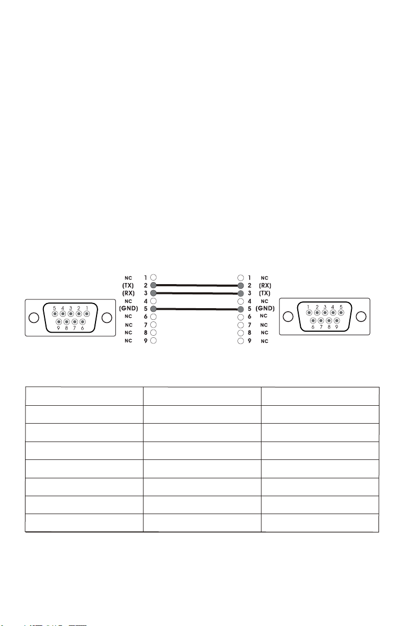
Serial Cable Pin Out
P-6014 RS-232 Pins
DB-9P, Female
PC RS-232 Pins
DB-9P, Male
Monitor 1 Commands
Function
Monitor 1, Select Camera 1
Monitor 1, Select Camera 2
Monitor 1, Select Camera 3
Monitor 1, Select Camera 4
Monitor 1, Select Next Cam
Monitor 1, Auto Cycle
Monitor 1, Request Status
8
ASCII Command
P64Z1S16
P64Z1S25
P64Z1S34
P64Z1S43
P64Z1SN[em]
P64Z1SR[nak]
P64Z1SF!
Hex Command
50 36 34 5A 31 53 31 36
50 36 34 5A 31 53 32 35
50 36 34 5A 31 53 33 34
50 36 34 5A 31 53 34 33
50 36 34 5A 31 53 4E 19
50 36 34 5A 31 53 52 15
50 36 34 5A 31 53 46 21
Page 9

Monitor 2 Commands
Function
Monitor 2, Select Camera 1
Monitor 2, Select Camera 2
Monitor 2, Select Camera 3
Monitor 2, Select Camera 4
Monitor 2, Select Next Cam
Monitor 2, Auto Cycle
Monitor 2, Request Status
Global Commands
Function
Global, Select Camera 1
Global, Select Camera 2
ASCII Command
P64Z2S15
P64Z2S24
P64Z2S33
P64Z2S42
P64Z2SN[can]
P64Z2SR[dc4]
P64Z2SF[sp]
ASCII Command
P64ZAS1&
P64ZAS2%
Hex Command
50 36 34 5A 32 53 31 35
50 36 34 5A 32 53 32 34
50 36 34 5A 32 53 33 33
50 36 34 5A 32 53 34 32
50 36 34 5A 32 53 4E 18
50 36 34 5A 32 53 52 14
50 36 34 5A 32 53 46 20
Hex Command
50 36 34 5A 41 53 31 26
50 36 34 5A 41 53 32 25
Global, Select Camera 3
Global, Select Camera 4
Global, Select Next Cam
Global, Auto Cycle
Global, Request Status
Global, Status Clear
P64ZAS3$
P64ZAS4#
P64ZASN[ht]
P64ZASR[enq]
P64ZASF[dc1]
P64ZASC[dc4]
50 36 34 5A 41 53 33 24
50 36 34 5A 41 53 34 23
50 36 34 5A 41 53 4E 09
50 36 34 5A 41 53 52 05
50 36 34 5A 41 53 46 11
50 36 34 5A 41 53 43 14
Note: these charts contains some ASCII commands that include non-standard
ASCII characters (characters which are not included on a standard keyboard).
When programming a controller with these functions, it may be necessary to
use the Hexadecimal equivalent shown in the far right hand column.
9
Page 10

Time Adjust Commands...
The following Time Adjust commands alter the amount of time each camera
view appears on the screen. Making time adjustments via these RS-232 will
override any physical adjustments made using the “Time Adjust” control on
the P-6014.
You can use either the global commands, which will set the time adjustment
on all the cameras, or you can use commands for the specific camera inputs.
This allows you to set different viewing times for each of the camera inputs.
For example, if camera 1 is the most important camera, you might want to set
it to show for 10 seconds, while cameras 2, 3, and 4 are set for 1 second.
These time settings will remain in the P-6014’s memory. For example, if you
send a command to switch to a specific camera view and then another
command to return back to the cycle mode, time settings for the cycle mode
will be the same as they were before you switched to the specific camera
view. Note: Any movement of the Time Adjust control will cause the unit to
enter the cycle mode and will override the time adjustment settings made via
the serial controller.
Function
Monitor 1, Cam 1, 1 Second
Monitor 1, Cam 1, 2 Seconds
Monitor 1, Cam 1, 3 Seconds
Monitor 1, Cam 1, 4 Seconds
Monitor 1, Cam 1, 5 Seconds
Monitor 1, Cam 1, 7.5 Seconds
Monitor 1, Cam 1, 10 Seconds
Monitor 1, Cam 1, 15 Seconds
Monitor 1, Cam 2, 1 Second
Monitor 1, Cam 2, 2 Seconds
Monitor 1, Cam 2, 3 Seconds
Monitor 1, Cam 2, 4 Seconds
Monitor 1, Cam 2, 5 Seconds
Monitor 1, Cam 2, 7.5 Seconds
Monitor 1, Cam 2, 10 Seconds
Monitor 1, Cam 2, 15 Seconds
Monitor 1, Cam 3, 1 Second
Monitor 1, Cam 3, 2 Seconds
Monitor 1, Cam 3, 3 Seconds
Monitor 1, Cam 3, 4 Seconds
Monitor 1, Cam 3, 5 Seconds
Monitor 1, Cam 3, 7.5 Seconds
Monitor 1, Cam 3, 10 Seconds
Monitor 1, Cam 3, 15 Seconds
Monitor 1, Cam 4, 1 Second
Monitor 1, Cam 4, 2 Seconds
Monitor 1, Cam 4, 3 Seconds
Monitor 1, Cam 4, 4 Seconds
Monitor 1, Cam 4, 5 Seconds
Monitor 1, Cam 4, 7.5 Seconds
Monitor 1, Cam 4, 10 Seconds
Monitor 1, Cam 4, 15 Seconds
10
ASCII Command
P64Z111X
P64Z112W
P64Z113V
P64Z114U
P64Z115T
P64Z116S
P64Z117R
P64Z118Q
P64Z121W
P64Z122V
P64Z123U
P64Z124T
P64Z125S
P64Z126R
P64Z127Q
P64Z128P
P64Z131V
P64Z132U
P64Z133T
P64Z134S
P64Z135R
P64Z136Q
P64Z137P
P64Z138O
P64Z141U
P64Z142T
P64Z143S
P64Z144R
P64Z145Q
P64Z146P
P64Z147O
P64Z148N
Hex Command
50 36 34 5A 31 31 31 58
50 36 34 5A 31 31 32 57
50 36 34 5A 31 31 33 56
50 36 34 5A 31 31 34 55
50 36 34 5A 31 31 35 54
50 36 34 5A 31 31 36 53
50 36 34 5A 31 31 37 52
50 36 34 5A 31 31 38 51
50 36 34 5A 31 32 31 57
50 36 34 5A 31 32 32 56
50 36 34 5A 31 32 33 55
50 36 34 5A 31 32 34 54
50 36 34 5A 31 32 35 53
50 36 34 5A 31 32 36 52
50 36 34 5A 31 32 37 51
50 36 34 5A 31 32 38 50
50 36 34 5A 31 33 31 56
50 36 34 5A 31 33 32 55
50 36 34 5A 31 33 33 54
50 36 34 5A 31 33 34 53
50 36 34 5A 31 33 35 52
50 36 34 5A 31 33 36 51
50 36 34 5A 31 33 37 50
50 36 34 5A 31 33 38 4F
50 36 34 5A 31 34 31 55
50 36 34 5A 31 34 32 54
50 36 34 5A 31 34 33 53
50 36 34 5A 31 34 34 52
50 36 34 5A 31 34 35 51
50 36 34 5A 31 34 36 50
50 36 34 5A 31 34 37 4F
50 36 34 5A 31 34 38 4E
Page 11

Monitor 2 Time Adjust Commands
Function
Monitor 2, Cam 1, 1 Second
Monitor 2, Cam 1, 2 Seconds
Monitor 2, Cam 1, 3 Seconds
Monitor 2, Cam 1, 4 Seconds
Monitor 2, Cam 1, 5 Seconds
Monitor 2, Cam 1, 7.5 Seconds
Monitor 2, Cam 1, 10 Seconds
Monitor 2, Cam 1, 15 Seconds
Monitor 2, Cam 2, 1 Second
Monitor 2, Cam 2, 2 Seconds
Monitor 2, Cam 2, 3 Seconds
Monitor 2, Cam 2, 4 Seconds
Monitor 2, Cam 2, 5 Seconds
Monitor 2, Cam 2, 7.5 Seconds
Monitor 2, Cam 2, 10 Seconds
Monitor 2, Cam 2, 15 Seconds
Monitor 2, Cam 3, 1 Second
Monitor 2, Cam 3, 2 Seconds
Monitor 2, Cam 3, 3 Seconds
Monitor 2, Cam 3, 4 Seconds
Monitor 2, Cam 3, 5 Seconds
Monitor 2, Cam 3, 7.5 Seconds
Monitor 2, Cam 3, 10 Seconds
Monitor 2, Cam 3, 15 Seconds
Monitor 2, Cam 4, 1 Second
Monitor 2, Cam 4, 2 Seconds
Monitor 2, Cam 4, 3 Seconds
Monitor 2, Cam 4, 4 Seconds
Monitor 2, Cam 4, 5 Seconds
Monitor 2, Cam 4, 7.5 Seconds
Monitor 2, Cam 4, 10 Seconds
Monitor 2, Cam 4, 15 Seconds
ASCII Command
P64Z211W
P64Z212V
P64Z213U
P64Z214T
P64Z215S
P64Z216R
P64Z217Q
P64Z218P
P64Z221V
P64Z222U
P64Z223T
P64Z224S
P64Z225R
P64Z226Q
P64Z227P
P64Z228O
P64Z231U
P64Z232T
P64Z233S
P64Z234R
P64Z235Q
P64Z236P
P64Z237O
P64Z238N
P64Z241T
P64Z242S
P64Z243R
P64Z244Q
P64Z245P
P64Z246O
P64Z247N
P64Z248M
Hex Command
50 36 34 5A 32 31 31 57
50 36 34 5A 32 31 32 56
50 36 34 5A 32 31 33 55
50 36 34 5A 32 31 34 54
50 36 34 5A 32 31 35 53
50 36 34 5A 32 31 36 52
50 36 34 5A 32 31 37 51
50 36 34 5A 32 31 38 50
50 36 34 5A 32 32 31 56
50 36 34 5A 32 32 32 55
50 36 34 5A 32 32 33 54
50 36 34 5A 32 32 34 53
50 36 34 5A 32 32 35 52
50 36 34 5A 32 32 36 51
50 36 34 5A 32 32 37 50
50 36 34 5A 32 32 38 4F
50 36 34 5A 32 33 31 55
50 36 34 5A 32 33 32 54
50 36 34 5A 32 33 33 53
50 36 34 5A 32 33 34 52
50 36 34 5A 32 33 35 51
50 36 34 5A 32 33 36 50
50 36 34 5A 32 33 37 4F
50 36 34 5A 32 33 38 4E
50 36 34 5A 32 34 31 54
50 36 34 5A 32 34 32 53
50 36 34 5A 32 34 33 52
50 36 34 5A 32 34 34 51
50 36 34 5A 32 34 35 50
50 36 34 5A 32 34 36 4F
50 36 34 5A 32 34 37 4E
50 36 34 5A 32 34 38 4D
Global Time Adjust Commands
Function
Global, All Cams, 1 Second
Global, All Cams, 2 Seconds
Global, All Cams, 3 Seconds
Global, All Cams, 4 Seconds
Global, All Cams, 5 Seconds
Global, All Cams, 7.5 Seconds
Global, All Cams, 10 Seconds
Global, All Cams, 15 Seconds
ASCII Command
P64ZAT1%
P64ZAT2$
P64ZAT3#
P64ZAT4”
P64ZAT5!
P64ZAT6[sp]
P64ZAT7[us]
P64ZAT8[rs]
Hex Command
50 36 34 5A 41 54 31 25
50 36 34 5A 41 54 32 24
50 36 34 5A 41 54 33 23
50 36 34 5A 41 54 34 22
50 36 34 5A 41 54 35 21
50 36 34 5A 41 54 36 20
50 36 34 5A 41 54 37 1F
50 36 34 5A 41 54 38 1E
11
Page 12

Channel Vision Technology will repair or replace any defect in material or workmanship which occurs
during normal use of this product with new or rebuilt parts, free of charge in the USA, for two years from
the date of original purchase. This is a no hassle warranty with no mail in warranty card needed. This
warranty does not cover damages in shipment, failures caused by other products not supplied by
Channel Vision Technology, or failures due to accident, misuse, abuse, or alteration of the equipment.
This warranty is extended only to the original purchaser, and a purchase receipt, invoice, or other proof
of original purchase date will be required before warranty repairs are provided.
Mail in service can be obtained during the warranty period by calling (800) 840-0288 toll free. A Return
Authorization number must be obtained in advance and can be marked on the outside of the shipping
carton.
This warranty gives you specific legal rights and you may have other rights (which vary from state to
state). If a problem with this product develops during or after the warranty period, please contact
Channel Vision Technology, your dealer or any factory-authorized service center.
Specifications: (typical @25º C)
P-6014
Dimensions: 5.5”W x 6.5”H x 1.5”D
Power Supply: 15VDC @ 1.6A
IR Frequency Range: 30-60kHz
Operating Temp: -10ºC to 50ºC
Audio Bandwidth: 20Hz - 20kHz
Video Crosstalk: -80dB
Video Bandwidth: DC - 20MHz
Video Crosstalk: -60dB
CAT5 Ports:
Max run length: 250ft (Camera input + Monitor output)
Max Camera Power: 12VDC @ 280mA
6210 Camera
Lens: 3.8mm
Resolution: 380 lines
S/N Ratio: More than 48dB
Min Illumination: 0.4 LUX @ F2.0
Power Consumption: 120mA
w ww .channelvi s io n.com
234 Fischer Avenue, Costa Mesa, California 92626 USA
(714)424-6500 (800)840-0288 (714)424-6510 fax
email: techsupport@channelvision.com
500-199 rev D
 Loading...