

Page 1

8x8 1080p COMPONENT VIDEO MATRIX SWITCHER
88
INPUT
POWER
PRO
By CHANNEL VISION
111122223333444455556666777788
OUTPU T OUTPU T
INPUT
P-1488
1080p 8x8 Component Video
Matrix Switcher
PRO
PRO
1
0
P-1488
Page 2
The P-1488 is a 1080p 8x8 Matrix Switcher for HDTV video and digital
audio signals that allows 8 different displays to view any of the 8 different
sources independently. It can be controlled via the front panel buttons, IR
remote control, or RS-232 commands.
Features:
!
RS-232 and IR control capabilities
!
Digital(PCM) & Analog Audio & Component Video switching
!
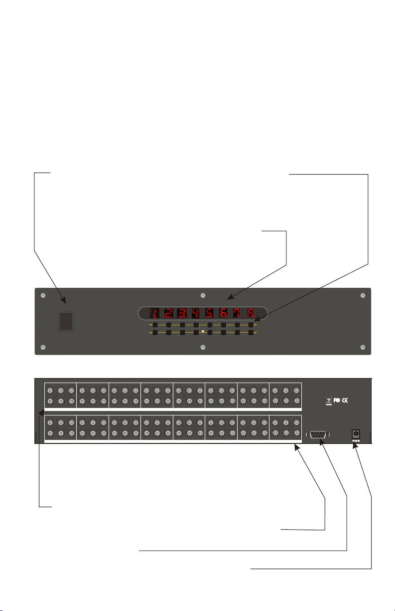
Easy to read LED display
Power switch
Source selection buttons
Route any input to any output
LED display shows
which input is selected
for each of the 8 outputs
By CHANNEL VISION
PRO
111122223333444455556666777788
OUTPU T OUTPU T
POWER
DigitalDigital
L/HL/H
R/VR/V
OUTPUT 8OUTPUT 8 OUTPUT 7OUTPUT 7 OUTPUT 6OUTPUT 6 OUTPUT 5OUTPUT 5 OUTPUT 4OUTPUT 4 OUTPU T 3OUTPUT 3 OUTPUT 2OUTPUT 2 OUTPUT 1OUTPUT 1
DigitalDigital
L/HL/H
R/VR/V
INPUT 8INPUT 8
DigitalDigital
L/HL/H
R/VR/V
OUTPUT 5OUTPUT 5OUTPUT 5OUTPUT 5 OUTPUT 5OUTPUT 5
DigitalDigital
L/HL/H
R/VR/V
INPUT 7INPUT 7 INPUT 6INPUT 6 INPUT 5INPUT 5 INPUT 4INPUT 4
OUTPUT 5OUTPUT 5OUTPUT 5OUTPUT 5 OUTPUT 5OUTPUT 5
INPUT
DigitalDigital
L/HL/H
R/VR/V
DigitalDigital
L/HL/H
R/VR/V
DigitalDigital
L/HL/H
R/VR/V
DigitalDigital
L/HL/H
R/VR/V
DigitalDigital
L/HL/H
R/VR/V
DigitalDigital
L/HL/H
R/VR/V
DigitalDigital
L/HL/H
R/VR/V
DigitalDigital
L/HL/H
R/VR/V
INPUT 3INPUT 3 INPUT 2INPUT 2 INPUT 1INPUT 1
8x8 1080p COMPONENT VIDEO MATRIX SWITCHER
88
INPUT
DigitalDigital
L/HL/H
R/VR/V
DigitalDigital
L/HL/H
R/VR/V
Y/GY/G Pb/BPb/B Pr/RPr/ RY/GY/G Pb/BPb/B Pr/RPr/ RY/GY/G Pb/BPb/B Pr/RPr/ RY/GY/G Pb/BPb/B Pr/RPr/ RY/GY/G Pb/BPb/B Pr/RPr/ RY/GY/G Pb/BPb/B Pr/RPr/ RY/GY/G Pb/BPb/B Pr/RPr/ RY/GY/G Pb/BPb/B Pr/RPr/R
R/VR/V
Y/GY/G Pb/BPb/B Pr/RPr/ RY/GY/G Pb/BPb/B Pr/RPr/ RY/GY/G Pb/BPb/B Pr/RPr/ RY/GY/G Pb/BPb/B Pr/RPr/ RY/GY/G Pb/BPb/B Pr/RPr/ RY/GY/G Pb/BPb/B Pr/RPr/ RY/GY/G Pb/BPb/B Pr/RPr/ RY/GY/G Pb/BPb/B Pr/RPr/R
R/VR/V
P-1488
Mode l: P-14 88Mode l: P-14 88
8x8 1080 pCOMP ONENT M ATRIX SW ITCHE R8x8 1080 pCOMP ONENT M ATRIX SW ITCHE R
RS-232RS-232
RoHS/9 5/ECRoHS/9 5/EC
INPUT
DC 12V
DigitalDigital
L/HL/H
DigitalDigital
L/HL/H
Component Video & Audio Outputs (to 8 zones)
Component Video & Audio Inputs (from 8 devices)
RS-232 Connector
12VDC Power Supply Connection (included)
2
Page 3

What is a Matrix Switcher?
Simultaneous access to multiple sources is what differentiates a matrix
switch from a simple switch which would only allow one source to be
viewed by multiple zones. A matrix switcher allows multiple users to
access signals from multiple source components. This type of
switching is ideal for whole-house application. For example, it may be
necessary to view the DVD player in the bedroom while, at the same
time, viewing the satellite receiver in the home theater. The P-1488 is
perfect for this application, as it allows 8 sources to be accessed by 8
different users simultaneously.
RO
W
F
F
P E
O
-4T
V
ON
TV-3
N
V8-
O
T
ATID
-2
7
N
V
-
I
T
TV
EST
ER8
V-1
T
TV-6
IT
W CH
-5
V-
V
S
T
A 5
ES
TV
RC
H
U
O
V-6
8 D
:
A
S
-1
AV-7
V
A
-8
V
2
A
V
A
MT
MT
A 3V-
n
n
io
io
s
s
4
i
i
-0 21P 1
v
v
AV-
el
el
nn
nn
a
a
h
h
c
c
Included Accessories
P-0121 Remote Control ... The hand held remote
can be used to control the P-1488 from the front of
the unit or from another room through the use of an
IR repeating system. The IR control codes can also
be downloaded from www.channelvision.com.
Power Supply... 12VDC@2000mA
Serial Control Cable... Use when connecting the
P-1488 to a serial control device.
Rack Ears... Use when mounting the P-1488 to a
19” rack.
How do the signals get to other rooms?
We suggest the use of a high quality video distribution system such as
Channel Vision’s P-1400 zero-loss video distribution system. This unit
delivers flawless video signals over a 25 meter pre-made cable. The
cable has been precisely constructed to match the pre-amplification
provided by the P-1400. The cable must not be shortened or the
benefits of the P-1400 will be negated.
P-1400
Pwr
le
b
de
n)
Vi o Ca
5’
7
ot shorte( n
Do
el
d
Mo
-140
P 0
NEL CH
NEL CH
N
N
TM
TM
A
A
O
NV
NV
er
nd
IO
IO
S
S
x
I
I
E te
o
PR
ossVide
ro-L
e
Z
G (Y)
deo
S-Vi
)
C
/
P
B B
B (
si
o te
Comp
)
/C
P
R R
12VDC
(
R
x
Au
500mA
25 meter cable
3
Page 4

Connection Diagram
Make all connections before applying power.
Front Left
Front Left
Center
Component Video
Front Right
Front Right
5.1 Amplifier
Digital Audio
Powered Sub
The P-1488 can allow 8 High Definition sources
to be distributed to 8 remote Home Theater systems.
Each system will have access to any of the 8 sources.
Use the digital audio connection for home theater
applications. The Left/Right analog audio connections can
be used If only stereo audio is needed.
DigitalDigital
L/HL/H
R/VR/V
OUTPUT 8OUTPUT 8 OUTPUT 7OUTPUT 7 OUTPUT 6OUTPUT 6 OUTPUT 5OUTPUT 5 OUTPUT 4OUTPUT 4 OUTPU T 3OUTPUT 3 OUTPUT 2OUTPUT 2 OUTPUT 1OUTPUT 1
DigitalDigital
L/HL/H
R/VR/V
INPUT 8INPUT 8
DigitalDigital
L/HL/H
R/VR/V
OUTPUT 5OUTPUT 5OUTPUT 5OUTPUT 5 OUTPUT 5OUTPUT 5
DigitalDigital
L/HL/H
R/VR/V
INPUT 7INPUT 7 INPUT 6INPUT 6 INPUT 5INPUT 5 INPUT 4INPUT 4
OUTPUT 5OUTPUT 5OUTPUT 5OUTPUT 5 OUTPUT 5OUTPUT 5
DigitalDigital
L/HL/H
R/VR/V
DigitalDigital
L/HL/H
R/VR/V
DigitalDigital
L/HL/H
R/VR/V
DigitalDigital
L/HL/H
R/VR/V
DigitalDigital
L/HL/H
R/VR/V
DigitalDigital
L/HL/H
R/VR/V
DigitalDigital
L/HL/H
R/VR/V
DigitalDigital
L/HL/H
R/VR/V
INPUT 3INPUT 3 INPUT 2INPUT 2 INPUT 1INPUT 1
Connect
Component Video &
Digital Audio
Blu-ray 1
Blu-ray 2
Blu-ray 3
Blu-ray 4
4
HD Sat 1
HD Sat 2
HD Sat 3
HD Sat 4
Y/GY/G Pb/BPb/B Pr/RPr/ RY/GY/G Pb/BPb/B Pr/RPr/ RY/GY/G Pb/BPb/B Pr/RPr/ RY/GY/G Pb/BPb/B Pr/RPr/ RY/GY/G Pb/BPb/B Pr/RPr/ RY/GY/G Pb/BPb/B Pr/RPr/ RY/GY/G Pb/BPb/B Pr/RPr/ RY/GY/G Pb/BPb/B Pr/RPr/R
DigitalDigital
L/HL/H
R/VR/V
DigitalDigital
L/HL/H
R/VR/V
DigitalDigital
L/HL/H
R/VR/V
Y/GY/G Pb/BPb/B Pr/RPr/ RY/GY/G Pb/BPb/B Pr/RPr/ RY/GY/G Pb/BPb/B Pr/RPr/ RY/GY/G Pb/BPb/B Pr/RPr/ RY/GY/G Pb/BPb/B Pr/RPr/ RY/GY/G Pb/BPb/B Pr/RPr/ RY/GY/G Pb/BPb/B Pr/RPr/ RY/GY/G Pb/BPb/B Pr/RPr/R
DigitalDigital
L/HL/H
R/VR/V
Mode l: P-14 88Mode l: P-14 88
8x8 1080 pCOMP ONENT M ATRIX SW ITCHE R8x8 1080 pCOMP ONENT M ATRIX SW ITCHE R
RoHS/9 5/ECRoHS/9 5/EC
RS-232RS-232
INPUT
DC 12V
Connect
serial controller to
the RS-232 port
Page 5
Control Codes
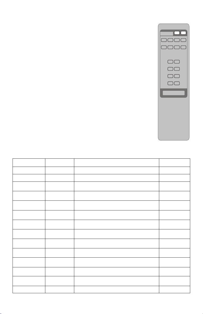
Using the Remote:
The model P-0120 remote control comes with the P-1488
Matrix Switcher to allow easy source selection without having
DES TINATI ON
TV-1
TV-5 TV-6 TV-7 TV-8
POWER
ON OFF
TV-2 T V-3 TV- 4
to use the buttons on the front the P-1488.
Choose a signal destination by pressing one of TV buttons,
then select a source by pressing one of the AV buttons. For
example, to select source 6 to be output to TV-4, press “TV-4”
then press “AV-6”.
Using advanced control systems:
For installations that require more sophistication the P-1488
also supports RS-232 making it well suited for use with
8:8 H DTV SWI TCHER
SOU RCES
AV-1
AV-2
AV-3
AV-4
P-01 21
channel vision
channel vision
AV-5
AV-6
AV-7
AV-8
Creston, AMX, and other automation systems that support
RS-232.
RS-232 Control Code:
Baud Rate: 9600, No Parity, 8Bit Data, 1 Start bit, 1 Stop bit.
Each transmission = 8 ASCII bytes
Note: When the P-1488 receives a command it will respond to the controller
with a confirmation code.
Command
SBSYSMON
SBSYSMOF
SBIxxO01
SBIxxO02
SBIxxO03
SBIxxO04
SBIxxO05
SBIxxO06
SBIxxO07
SBIxxO08
SBSYSMLK
SBSYSMUK
SBALLRST
SBASKSTA
Function Description
Power on
Power off
Channel 1
setting
Channel 2
setting
Channel 3
setting
Channel 4
setting
Channel 5
setting
Channel 6
setting
Channel 7
setting
Channel 8
setting
Locked toggle
on
Locked toggle
off
reset
System power on
System power off
Changes the 1st output signal. xx is
the selected source. xx=(01,02, ..., 06).
Changes the 2nd output signal. xx is
the selected source. xx=(01,02, ..., 06).
Changes the 3rd output signal. xx is
the selected source. xx=(01,02, ..., 06).
Changes the 4th output signal. xx is
the selected source. xx=(01,02,...,06).
Changes the 5th output signal. xx is
the selected source. xx=(01,02, ..., 06).
Changes the 6th output signal. xx is
the selected source. xx=(01,02, ..., 06).
Changes the 7rd output signal. xx is
the selected source. xx=(01,02, ..., 06).
Changes the 8th output signal. xx is
the selected source. xx=(01,02,...,06).
When locked on, only RS232 control is
enabled (front panel buttons are disabled)
When locked off, RS232, IR, and front
panel buttons are enabled
Unit is reset and every output comes
from the 1st input
Ask status
Request status information.
Response
SBALONAK
SBALOFAK
SBUDxxO1
SBUDxxO2
SBUDxxO3
SBUDxxO4
SBUDxxO5
SBUDxxO6
SBUDxxO7
SBUDxxO8
SBSYSLOK
SBSYSULK
SBRSTACK
SBSTATAK
TM
TM
5
Page 6

Parsing the Status Response
Many advanced control systems may require status feedback from the
matrix switcher. When the switcher responds to a status request, it will
show all of the current input and output settings.
The following example is a response to the status request command:
SBASKSTA
Example:
Response
SBSTATAK
SBALONAK
SBUD00000301
SBUD00000102
SBUD00000103
SBUD00000104
SBUD00000105
SBUD00000806
SBUD00000507
SBUD00000408
SBSYSULK
Parsing the Response
Each of the channels will report back their input/output settings. The
input/output data will be preceded by the prefix: SBUD0000.
Programmers can store the 4 characters that follow the prefix. The first
two characters indicate the input and the last two characters indicate
the output.
{
{
{
Meaning
Acknowledge the request for status
System Power On
SBUD0000{input-3}{output-1}
SBUD0000{input-1}{output-2}
SBUD0000{input-1}{output-3}
SBUD0000{input-1}{output-4}
SBUD0000{input-1}{output-5}
SBUD0000{input-8}{output-6}
SBUD0000{input-5}{output-7}
SBUD0000{input-4}{output-8}
System control is unlocked
SBUD0000{input-3}{output-1}SBUD00000301
Prefix
Input-3
6
Output-1
Page 7

Note: Some controllers may not accept ASCII strings. The HEX equivalents
for each command are listed below.
Function
Power On
Power Off
Channel 1
Setting
Channel 2
Setting
Channel 3
Setting
Channel 4
Setting
Channel 5
Setting
Channel 6
Setting
Channel 7
Setting
Channel 8
Setting
Locked Toggle
On
Locked Toggle
Off
Reset
Ask Status
HEX Command Description
53,42,53,59,53,4D,4F,4E System power on
53,42,53,59,53,4D,4F,46
53,42,49,30,xx,4F,30,31
53,42,49,30,xx,4F,30,32 Set output 2. Input is xx.
53,42,49,30,xx,4F,30,33 Set output 3. Input is xx.
53,42,49,30,xx,4F,30,34
53,42,49,30,xx,4F,30,35
53,42,49,30,xx,4F,30,36 Set output 6. Input is xx.
53,42,49,30,xx,4F,30,37 Set output 7. Input is xx.
53,42,53,59,53,4D,4C,4B
53,42,53,59,53,4D,55,4B
53,4241,4C,4C,52,53,54
System power off
Set output 1. Input is xx.
xx=(31,32, 33, 34, ..., 38).
xx=(31,32, 33, 34, ..., 38).
xx=(31,32, 33, 34, ..., 38).
Set output 4. Input is xx.
xx=(31,32, 33, 34, ..., 38).
Set output 5. Input is xx.
xx=(31,32, 33, 34, ..., 38).
xx=(31,32, 33, 34, ..., 38).
xx=(31,32, 33, 34, ..., 38).
Set output 8. Input is xx.
xx=(31,32, 33, 34, ..., 38).
When locked on, (disables
buttons) only RS232 works
When locked off, RS232, IR
& front buttons are enabled
Sets all outputs to input 1
Request status information.
HEX Response
53,42,41,4C,4F,4E,41,4B
53,42,41,4C,4F,46,41,48
53,42,55,44,30,xx,30,31
53,42,55,44,30,xx,30,32
53,42,55,44,30,xx,30,33
53,42,55,44,30,xx,30,34
53,42,55,44,30,xx,30,35
53,42,55,44,30,xx,30,36
53,42,55,44,30,xx,30,37
53,42,55,44,30,xx,30,3853,42,49,30,xx,4F,30,38
53,42,53,59,53,4C,4F,4B
53,42,53,59,53,55,4C,4B
53,42,52,53,54,41,43,4B
53,42,53,54,41,54,41,4B53,42,41,53,4B,53,54,41
Specifications: (typical)
Video Supported: 480i/p, 720p, & 1080i/p
Video Bandwidth: 325MHz (-3dB), 200mVp-p
Video Crosstalk: <80dB @ 5MHz
Audio Supported: Digital(PCM) & Analog Audio, 20Hz~20kHz
Control Method: RS-232 and hand held remote
Power Supply: 12VDC @ 2A
Power Consumption (max): 1.6A
Safety Approvals: CE, FCC, RoHS(2002/95/EC)
Dimensions: 3.46"H x 17.37”W x 7.87”D
Shipping Weight 3.25Kgs / 5.42lbs.
Specifications subject to change without notice.
7
Page 8

1
Channel Vision Technology will repair or replace any defect in
material or workmanship which occurs during normal use of this
product with new or rebuilt parts, free of charge in the USA, for one
year from the date of original purchase. This is a no hassle warranty
with no mail in warranty card needed. This warranty does not cover
damages in shipment, failures caused by other products not supplied
by Channel Vision Technology, or failures due to accident, misuse,
abuse, or alteration of the equipment. This warranty is extended only
to the original purchaser, and a purchase receipt, invoice, or other
proof of original purchase date will be required before warranty
repairs are provided.
Mail in service can be obtained during the warranty period by calling
(800) 840-0288 toll free. A Return Authorization number must be
obtained in advance and can be marked on the outside of the shipping
carton.
This warranty gives you specific legal rights and you may have other
rights (which vary from state to state). If a problem with this product
develops during or after the warranty period, please contact Channel
Vision Technology, your dealer or any factory-authorized service
center.
Channel Vision products are not intended for use in medical,
lifesaving, life sustaining or critical environment applications.
Channel Vision customers using or selling Channel Vision products
for use in such applications do so at their own risk and agree to fully
indemnify Channel Vision for any damages resulting from such
improper use or sale.
w ww .c ha n ne lv is io n. co m
234 Fischer Avenue, Costa Mesa, California 92626 USA
(714)424-6500 (800)840-0288 (714)424-6510 fax
email: techsupport@channelvision.com
500-252 revB
 Loading...