

Page 1
Zone 1
i eAct v
Zo e n
2
Link
In
Model
P-1044
i eAct v
PRO
CH AN NEL
CH AN NEL
VI SI ON
VI SI ON
TM
TM
A i
Z ne 3
o
A i e
ct
oZ ne 4
v
ect v
Li kn
Out
Source 2 IRSource 1 IR
Source 1 Source 2
Source 3 IR
Source 3
Source 4 IR
Source 4
Common IR
IR Data
Power
+24VDC
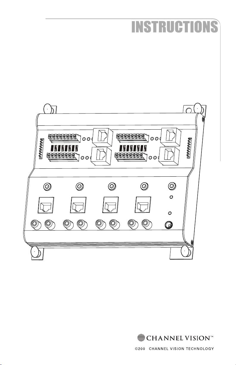
P-1044
4-Source/4-Zone CAT5 Audio Matrix
By
6
Page 2
The P-1044 is a 4-source, 4-zone matrix switcher for Channel Vision’s
CAT5 audio system. It allows up to four different sources to be played in
four different zones simultaneously, making it perfect for families with a
variety of listening interests. Controlling your music is easy with the
P-1044’s source specific IR repeating which allows independent control
of identical source components. For example, two identical CD players
can be controlled independently.
Features:
!
LED status indicators
!
Source specific IR routing
!
Input connections: RJ-45 or RCA
!
Output connections: RJ-45 or 110 punchdown
!
Compatible with Channel Vision’s AB-124 amplified keypad
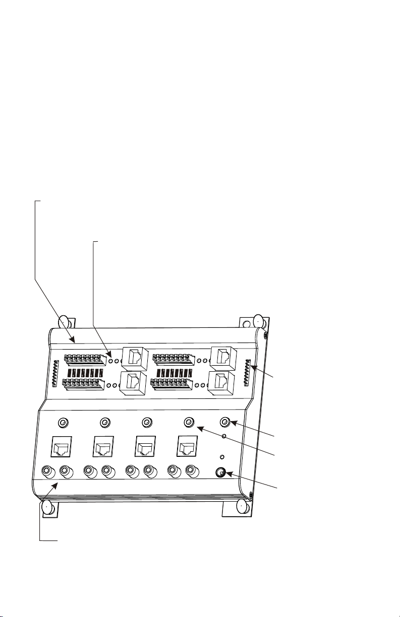
4 Zone Outputs
Allows connection of AB-124 keypads
Provides for either 110 or RJ-45 (see note under LED Indicators)
LED Indicators
Blue LED indicates that the zone is active.
Red LED indicates which connector is being used.
Note: Each zone will only support 1 keypad.
If keypads are connected to both the RJ-45 and 110 connectors, only
the keypad connected to the RJ-45 will be active and the red LED
near the RJ-45 connector will be illuminated.
Zon 1
L
in
k
nI
Source 1 Source 2
Model
P-1044
Source 2 IRSource 1 IR
e
ivAct e
Zone 2
ivAct e
CH ANN EL
CH ANN EL
VI SIO N
VI SIO N
PRO
Source 3 IR
Source 3
TM
TM
Source 4 IR
Source 4
Zone 3
Act
Zone 4
iv
e
ivAct e
Lin
Link In/Link Out
k
Allows for easy expansion
tOu
by transferring IR signals to
multiple units.
Common IR
IR Data
Power
+24VDC
Common IR output
IR output from all zones
Source specific IR outputs
Only emits IR when a zone has
this source selected
Power Connector
Use AB-T2454 power supply
Audio Source inputs
Use RCA inputs to connect conventional audio sources.
Use RJ-45 inputs to connect input modules such as AB-202, AB-301, and AB-311.
2
Page 3
Compatibility
The P-1044 adheres to the same protocols as Channel Vision’s other CAT5
audio hubs to ensure maximum compatibility. However, some amplified
keypads (such as the AB-114) will not provide control of source selection. If
the keypad provides IR pass through (as does the AB-114), you can use an
A0501 remote control to make source selections. For best results we
recommend using the AB-124 amplified keypad.
How it Works
The P-1044 is a matrix switcher for Channel Vision’s CAT5 audio system. Any
zone can independently select and listen to any source at any time. Source
selection can be done either from an AB-124 amplified keypad or by using the
A0501 remote control. For details on the A0501 remote control, please refer to
the section of this manual titled “Using the A0501 Remote Control.” The basic
operation of the AB-124 is described below.
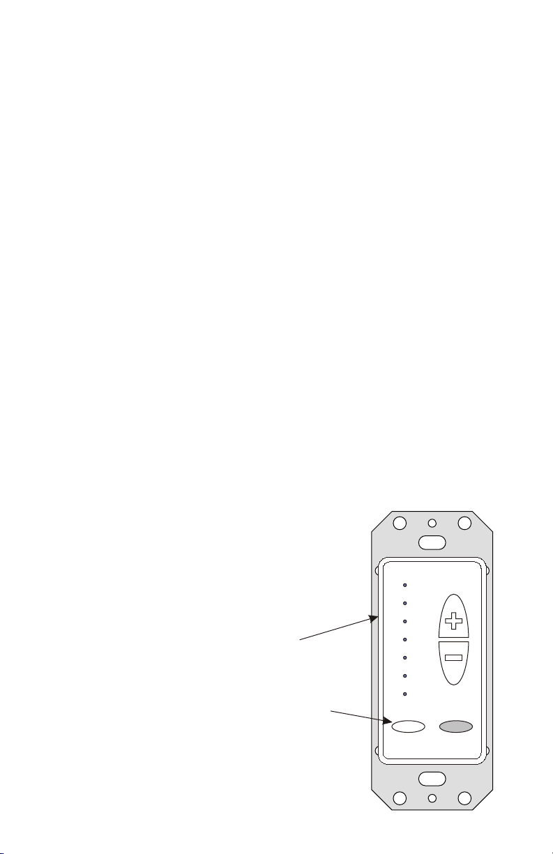
Using the AB-124 Amplified keypad...
The Pwr (power) button located at the lower left of the keypad is also used for
source selection. When the AB-124 is powered on, press and release the
power button to scroll through the input sources. As you change sources,
you’ll notice that the top 4 LEDs illuminate corresponding to the source you
have selected. When source one is selected, the first LED is illuminated,
when source two is selected, the second LED is illuminated, and so on.
After a source is selected the LED will stay lit for 5
seconds, then it will return to showing the current
volume level.
Volume adjustments can be made using the
up/down buttons to the right hand side of the
keypad. The keypad can be controlled from the
A0501 remote control (see the section titled: Using
the A0501 remote control for more details).
C HA NN E L V I SIO N
{
These four LEDs illuminate to indicate
which source input is selected.
The Pwr button is used for source selection.
Pwr
Source
3
Page 4
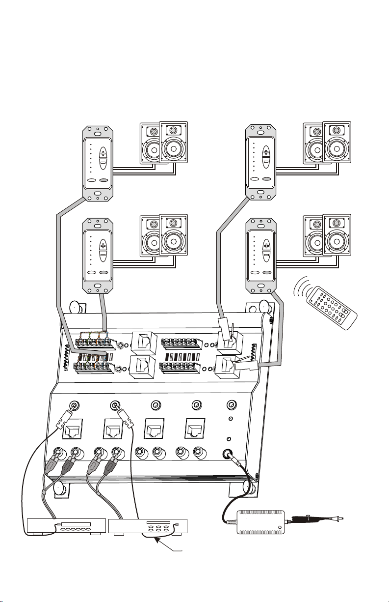
Basic Application
A basic system can be created with four amplified keypads (model AB-124)
and four pairs of speakers. The source components can be controlled by
pointing their remote control at the IR sensor in the AB-124 keypad.
CHA NNE L VI SI ON
Pwr
Source
CHA NNE L VI SI ON
Pwr
Source
ink L
In
Source 1 Source 2
Model
P-1044
Source 2 IRSource 1 IR
Zone 2
oZ
ne 1
ivAct
ivAct e
e
CH ANN EL
CH ANN EL
VI SIO N
VI SIO N
PRO
Source 3 IR
Source 3
CHA NNE L VI SI ON
Pwr
Source
CHA NNE L VI SI ON
Pwr
Source
3
6
2
9
5
1
8
4
0
7
e
wr
o
P
Zone
3
Act
i
ve
Zone 4
iAct
ve
TM
TM
Source 4 IR
Source 4
Common IR
IR Data
Power
+24VDC
Li
n
k
O
u
t
Integrated IR repeating
allows sources to be
controlled from any
room.
Sat radio
4
CD player
(Optional) IR emitters
(Optional) IR emitters
AB-T2454
power supply
(included)
Page 5

Expanding The System
Larger systems consisting of more than 4 zones can be created by
adding a second P-1044. Use RCA ‘Y’ connectors to split the audio
sources into both units. Use the provided ribbon cable to connect the
“Link” terminals. This will allow IR signals received through one P-1044 to
be transmitted to the other P-1044.
1 of 8 possible Amplified keypads
CHAN NEL VIS IO N
Pwr
Use the ribbon cable provided to
connect “Link Out” from one unit to the
“Link In” of the other unit. This will
transfer IR signals between units.
Source
Integrated IR repeating
allows sources to be
3
6
2
9
5
1
controlled from any
8
4
0
7
r
we
o
P
room.
Ln
i
k
In
Model
P-1044
Source 1 Source 2
Model
P-1044
Zone 1
Active
Zon
e
2
Active
CHA NN EL
CHA NN EL
TM
TM
VIS ION
VIS ION
PRO
Source 3 IR
Source 2 IRSource 1 IR
Source 3
eZon
1
Active
Z n
o e 2
Active
CHA NN EL
CHA NN EL
TM
TM
VIS ION
VIS ION
PRO
Source 3 IR
Source 2 IRSource 1 IR
Source 3
Source 4 IR
Source 4
Zo
n
e 3
Active
Zo e 4n
Active
Common IR
IR Data
Power
+24VDC
kLin
Out
i kL
n
In
Source 1 Source 2
Source 4 IR
Source 4
o
e3Z n
Active
Z
o e
n
4
Active
Common IR
+24VDC
Use RCA ‘Y’ connectors (such as the 3104)
to split the audio feeds into both units.
CD player
1 of 4 possible source devices.
Note: both units shown above must be powered by an AB-T2454 power supply.
These power supplies are not shown in the diagram above.
i kL
n
Out
IR Data
Power
5
Page 6

Using Different Input Devices Integrating the P-1044 with other products
The P-1044 can accept signals from either a standard analog audio
output (via RCA inputs) or a CAT5 audio output from one of Channel
Vision’s CAT5 audio input modules.
AB-311
Note: the AB-311 is compatible
with many different iPods . The
iPod mini is shown for reference only.
R
AB-301
IR emitters
Line level inputs
CD player
nLink I
Model
P-1044
Source 2 IRSource 1 IR
Source 1 Source 2
AB-202
AB-202
OUTPUT
Ac
Zone 2
Acit
o
e1Z n
t
i
ve
ve
AUDIO
L
CHA NN EL
CHA NN EL
VIS ION
VIS ION
PRO
Source 3 IR
Source 3
R
By CH ANN EL V ISI ON
TM
TM
STATUS
12VDC
TM
IR EMITTERS
STATUS
Source 4 IR
Source 4
IR
Zone 3
Active
Zone 4
Active
Common IR
IR Data
Power
+24VDC
CD player
Receiver
L
n Oui k
t
CD player
Receiver
Use Left/Right Audio RCA Outputs
from the “Tape Out” or “Monitor Out”
on the A/V receiver
Left/Right Audio RCA Outputs
from any standard component
Use Left/Right Audio RCA
Outputs from the “Tape Out”
or “Monitor Out”
on the A/V receiver
6
Page 7

Many different components can be integrated together. The system below
integrates a single-source CAT5 audio hub (model P-1014) as well as
telephone paging modules. The keypads connected to the P-1014 will act
as sub-zones to the P-1044. These sub-zones will all play the same audio
which is perfect for common areas such as hallways, bathrooms, kitchen,
or dinning room. Adding the C-0920 and P-0925 allows paging to occur
in these common areas.
CHANN EL V ISI ON
Pwr
Source
AB-124
From TELCO
CHANN EL V ISI ON
Pwr
Source
Bedroom 1
Sat radio
DVD player
Hallway
C-0920
CHANN EL V ISI ON
Pwr
Source
Bathroom
k In
Lin
CHANN EL V ISI ON
Pwr
Source
Dining Room
o
M
n
tc r
a
r l e
i
ol
n
a
V
o
j
l
o
e
ud
d
M
l e
s t
u
t
m
me
5
092
-
P
n
tg
u
p
t
u
O
e
a
P
o
n
o
m
25
P-09
44
P-10
ne 1
e
v
i
Act
ne 2
ive
Act
ANN EL
ANN EL
H
H
C
C
IO
IO
S
S
VI
VI
del
o
PRO
M
44
0
1
-
P
2IR
ce
our
S
R
1 I
ouS rce
2
Source
rce 1
u
So
Model
014
P-1
e 1n
Zo
em
yst
S
t
pu
n
I
AT5 udio D
x
1 4 C
em
yst
S
Signal
ri r yP o it
Local
la
c
R
Lo
L
Input
ne 3
vAct
i e
e
n 4
uk O t
v
ti e
Ac
TM
TM
N
N
Common IR
ourS ce 4 IR
3 IR
rce
ou
S
3
r
Sou ce
IR Data
er
Pow
4VDC
+2
4
ce
uro
S
Zone 2
A
CHANN EL V ISI ON
Zone 3
s
i tributio
IR
ers
ittm
E
1
P- 014
CHANN EL V ISI ON
Pwr
Source
CHANN EL V ISI ON
Pwr
Source
Pwr
Source
4
e
n
Zo
ule
n Mod
Bedroom 2
Bedroom 3
Kitchen
Expansion
utputO
Power
s
Statu
+ VD24
+12VDC
C
CD player
AM/FM radio
7
Page 8

Using the A0501 remote control
The A0501 is designed to allow you to control your P-1044 without having to
touch the buttons on the AB-124. Simply point the A0501 remote control at the
IR sensor located at the bottom of the AB-124 and press the desired button.
Zone Power - Turns off the output of the P-1044.
Power - Turns off the AB-124.
C
H N NE N
A
MODEL
A0501
Z NE
O
POWER
VOL
L V
T
M
IS I
O
PO
WER
S
O
U
R
C
E
1
2
3
4
MUTE
LED indicators
on the AB-124
will light when
source buttons
are pressed on
the A0501.
VOL - Controls volume
for the keypad
C H AN NE L V I SI ON
Pwr
Source
TM
HANNE L
V
IC
SI
ON
POWER
M
O EL
D
A 5010
1
S
O
2
U
R
C
3
E
4
ZONE
POWER
MUTE
VOL
Downloading IR commands...
If you don’t have access to the A0501 remote and you need to program a
learning remote, you can download the IR codes from the internet. IR codes
compatible with the Philips Pronto remote controls can be downloaded from
the following websites:
www.channelvision.com (codes in Hex format)
www.remotecentral.com (codes in Pronto format)
8
Page 9

Mounting Options
The P-1300 from Channel
Vision’s Pro-series product line is
the perfect home for the P-1044.
The P-1300 is a hinged plate
designed to fit into a standard 19”
rack.
The P-1300 hinges open to
Zo e
n 1
Active
Zone 2
L
i
nk
ctiveA
In
M
od l
e
P
-1
04
4
o
e1 IS urc R
r
2
ISouce
R
S
o
uc
r
e 1
So
e2urc
Zone 3
Active
Zo e 4
n
Active
iL
nk
A
A
NNE
NNE
LCH
LCH
MT
MT
P
V
V
I
I
S
S
R
I
I
O
O
N
N
O
S urce IRo
3
Source 3
tOu
Sou
ce 4 Rr
I
Co mon Im R
I
R t
Da
a
Power
Source 4
+24VDC
The P-1044 can also be mounted in a standard structured wiring enclosure
or screwed to a wall or flat surface as shown below.
maintain a clean look and
provide easy access for
servicing equipment.
For wall mounting:
Link
Out
Power
IR Data
+24VDC
Common IR
ActiveActive
Zone 4
Zone 3
Zone 1
Zone 2
Source 4
Source 4 IR
TM
TM
Source 3
Source 3 IR
VISI ON
VISI ON
CHAN NEL
CHAN NEL
PRO
Active Active
Source 2 IRSource 1 IR
Model
P-1044
Source 1 Source 2
In
Link
Cut or remove the
nylon snap pins.
Zone 1
Act e
iv
Z
o 2
ne
inL
k
Active
In
M
ode
l
C
C
H
H
A
A
NN
NN
L
L
E
E
TM
TM
-
104
4P
PRO
V
V
I
I
S
S
O
O
NI
S rce 1 IR
ou
Sou
re 1
c
NI
S
rce 2 IRou
S
ou
rce 3 IR
S
So
u
rce 2
Source 3
Sou
re 4
Zone 3
Act
eiv
Zone 4
Active
Link
Out
rce 4 IRou
Common IR
aIR D ta
Power
c
+24VDC
Install screws in empty holes.
9
7
Page 10

Connection Tips and Troubleshooting
1) Be sure you have connected the CAT5 cable correctly. Note that the
stripe/solid pattern should match the labels on the product. Misswiring can cause distorted sound or prevent the system from working
at all!
2) Be sure you have connected the speakers in phase. Follow the label
on the product. Out of phase speakers can rob the system of its bass,
especially when driving dual-voice-coil speakers.
3) Be sure IR emitters are directly over the IR sensor for all devices you
wish to control.
4) If no audio is heard in a zone... inspect the status LEDs for that zone.
The red LED next to the output you are using should be illuminated
and so should the blue LED labeled “Active”. Note that there are two
red LEDs for each zone output, one for RJ-45 connector and one for
the 110 connector. These red LEDs indicate which output connector
is being used (only one can be used at a time). If you connect
keypads to both of these connectors simultaneously, only the RJ-45
output will be activated.
5) If no audio is heard and the blue LED labeled “Active” is not lit...
Make sure that audio is playing (it must be playing for the Active light
to come on). If music is playing, re-issue the source command (i.e.
re-select the source using the remote or keypad).
6) If a CAT5 wire is connected to the P-1044, make sure the other end is
terminated with a keypad. If the CAT5 wire is left un-terminated while
the other end is attached to the P-1044, it may be possible for the
conductors in the rough end of the CAT5 to short together and cause
problems for the system.
7) If one of the source inputs is not working try connecting that source
into one of the working source inputs. If the problem persists check
the cabling between the source and the P-1044.
10
Page 11

Stripping and Connecting CAT5 Wire
CAT5 cable should be stripped with a proper stripping tool, such as Channel
Vision’s J-110 tool.
1. Place the CAT5 between the blade and the first notch of the J-110 tool.
CAT5
Blade
2. Rotate the tool only once. Multiple
turns will cause you to cut into the
inner wires.
3. Inspect the inner wires for damage.
If any wires are cut start over at step 1.
Check for damage
TIA-568A RJ-45 Modular Plug
Side view:
Top view:
Specifications: (typical @25º C)
Operating Voltage : 24±.5VDC
Cable requirements: CAT5 or better
Speaker impedance: 6-8 ohm
IR repeating: 30-60kHz
IR sensor range (AB-124): 40’@40kHz, 25’@56kHz
Operating Temperature: -10ºC to +50ºC
Specifications subject to change without notice.
Rotate
1 turn only
Slight
pressure
Green/White
Green
Orange/White
Blue
Blue/White
Orange
Brown/White
Brown
iPod is a trademark of Apple Computer, Inc., registered in the U.S. and other countries.
11
Page 12

Channel Vision Technology will repair or replace any defect in
material or workmanship which occurs during normal use of this
product with new or rebuilt parts, free of charge in the USA, for two
years from the date of original purchase. This is a no hassle warranty
with no mail in warranty card needed. This warranty does not cover
damages in shipment, failures caused by other products not supplied
by Channel Vision Technology, or failures due to accident, misuse,
abuse, or alteration of the equipment. This warranty is extended only
to the original purchaser, and a purchase receipt, invoice, or other
proof of original purchase date will be required before warranty
repairs are provided.
Mail in service can be obtained during the warranty period by calling
(800) 840-0288 toll free. A Return Authorization number must be
obtained in advance and can be marked on the outside of the shipping
carton.
This warranty gives you specific legal rights and you may have other
rights (which vary from state to state). If a problem with this product
develops during or after the warranty period, please contact Channel
Vision Technology, your dealer or any factory-authorized service
center.
500-129 revB
 Loading...