

Page 1
INSTRUCTIONS
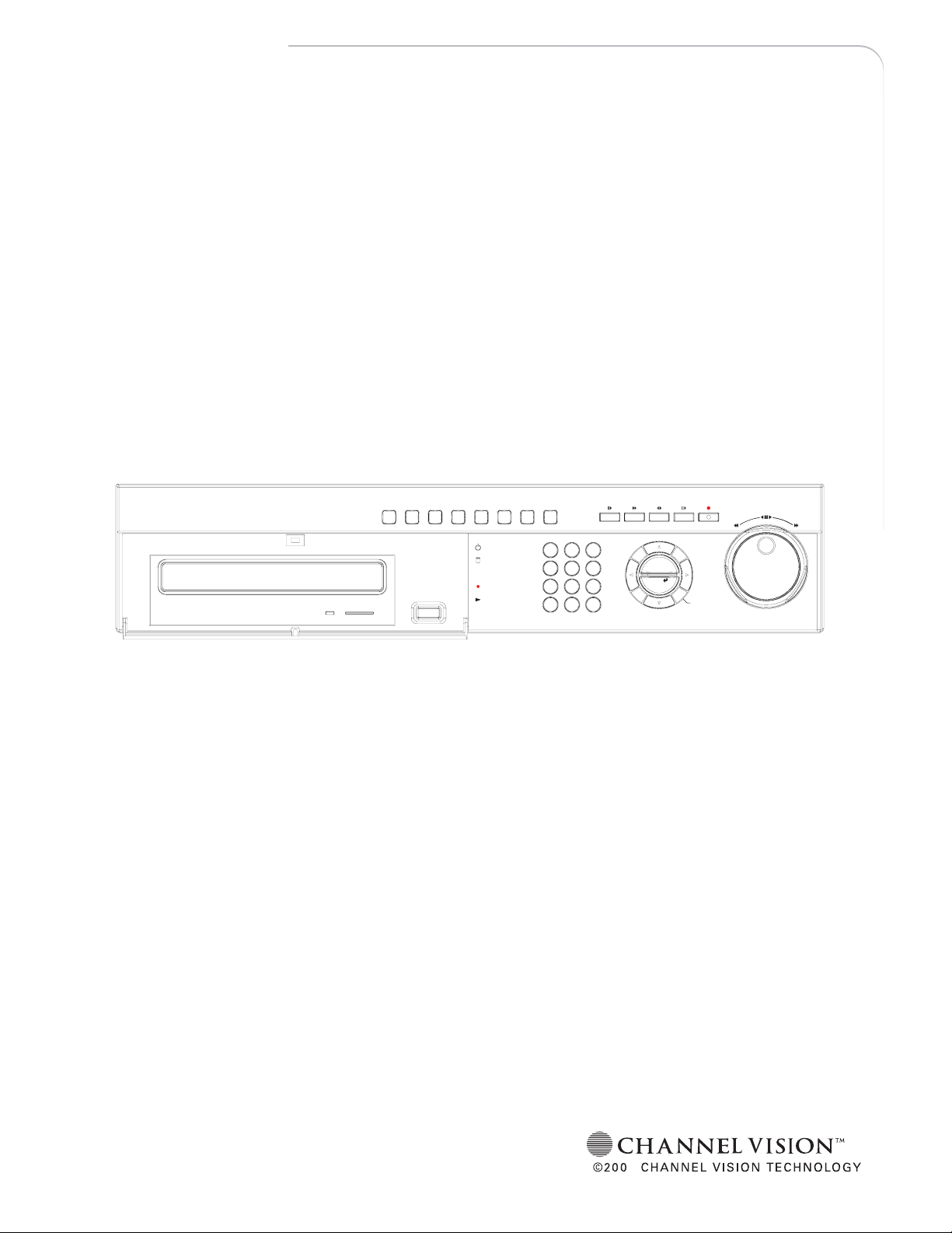
DVR-4N
DVR-8N
PRESET"'''
SPOT SEARCHFREEZEFUNCTION AUTO PTZ COPY LIVE/PB
STANDBY
HDD
RX/TX
!
REC
PLAY
CAMERA /NUMBER INPUT
41526
+10
0
FF
;
D-ZOOM
HOME
REW
;
DIRSLOW FAST PLAY/PAUSE REC
ALARM
RESET
MENU
ESC
STATUS
PIP
3
978
MULTI
DVR-16N
4/8/16CameraDVR
6
Page 2

W
ARNING
This symbol is intended to alert the user to the presence of unprotected
“Dangerous voltage" within the product's enclosure that may be strong
enough to cause a risk of electric shock.
This symbol is intended to alert the user to the presence of
important operating and mainten ance (servicing) instructions in the literature
accompanying the appliance.
WARNING
TO REDUCE THE RISK OF FIRE OR ELECTRIC SHOCK, DO NOT EXPOSE THIS
APPLIANCE TO RAIN OR MOISTURE.
NOTE: This equipment has been tested and found to comply with the limits for a class digital
device, pursuant to part 15 of the FCC Rules. These limits are designed to provide
reasonable protection against harmful interference when the equipment is operated in
a commercial environment. This equipment generates, uses, and can radiate radio
frequency energy and, if not installed and used in accordance with the instruction
manual, may cause harmful interference to radio communications. Operation of this
equipment in a residential area is likely to cause harmful interference in which case the
user will be required to correct the interference at his own expense.
Disposal of Old Electrical & Electronic Equipment (Applicable in the European
Union and other European countries with separate collection systems)
This symbol on the product or on its packaging indicates that this product shall not be treated as
household waste. Instead it shall be handed over to the applicable collection point for the
recycling of electrical and electronic equipment. By ensuring this product is disposed of correctly,
you will help prevent potential negative consequences for the environment and human health,
which could otherwise be caused by inappropriate waste handling of this product. The recycling
of materials will help to conserve natural resources. For more detailed information about
recycling of this product, please contact your local city office , your household waste disposal
service or the shop where you purchased the product.
1
Page 3

PRECAUTION
All the safety and operating instructions must be read before the unit is operated.
• Make sure to switch the power off before you install the DVR.
• There is the danger of an electric shock if the DVR is opened by an unqualified service
engineer or installer.
• Avoid using the DVR outside of the reference temperature and humidity indicated in the
specification.
• Avoid exposing the DVR to violent movement or vibration.
• Do not use or store the DVR in direct sunlight or near to any source of heat.
• Do not place any object into the holes used for air circulation.
• Always use the DVR in a well ventilated location to prevent overheating.
• Risk of explosion if battery is replaced by an incorrect type.
• Dispose of used batteries according to the instructions.
• When the system is overheated, the below warning message will be displayed at the
monitor.
“ SYSTEM IS OVERHEATED, TURN THE POWER OFF AND CHECK COOLING FAN” In this
case, do the power off right away and check the cooling fan working.
• The HDD is recommended to use enhanced IDE Hard Disc Drive type made by Maxtor,
Western Digital, Hitachi and IBM.
2
Page 4

CONTENTS
CONTENTS
CHAPTER 1 FEATURES..............................................................................4
CHAPTER 2 PACKING DETAIL....................................................................6
CHAPTER 3 LOCATION AND CONTROL .....................................................7
3.1 FRONT PANEL CONTROLS............................................7
3.2 REAR PANEL CONNECTORS.........................................8
CHAPTER 4 INSTALLATION........................................................................ 9
4.1 TOTAL CONNECTION LAY-OUT........................................9
4.2 INDIVIDUAL CONNECTION............................................. 10
CHAPTER 5 OPERATION.......................................................................... 14
5.1 FACTORY DEFAULT.....................................................14
5.2 FRONT PANEL CONTROLS..........................................17
5.3 REMOTE CONTROLLER...............................................35
5.4 MOUSE CONTROL ....................................................... 36
CHAPTER 6 MENU SETUP........................................................................37
6.1 QUICK SETUP.............................................................. 37
6.2 SCREEN.......................................................................39
6.3 RECORD ...................................................................... 46
6.4 EVENT..........................................................................53
6.5 SYSTEM.......................................................................57
6.6 LINK.............................................................................65
6.7 SEARCH.......................................................................72
6.8 COPY ...........................................................................72
6.9 EXIT.............................................................................73
CHAPTER 7 EXTERNAL TERMINAL INFORMATION..................................74
7.1 RS-422/485...................................................................74
7.2 T.ADJ ........................................................................... 74
7.3 RELAY OUT..................................................................75
7.4 ALARM .........................................................................75
7.5 VGA..............................................................................76
7.6 SERIAL.........................................................................76
7.7 ETHERNET / USB.........................................................77
7.8 REMOTE ......................................................................77
CHAPTER 8 SPECIFICATIONS..................................................................78
8.1 INSTALLL THE INTERNAL HARD DISK DRIVE(S).........81
CHAPTER 9 NETWORK VIEWER...............................................................82
9.1 INSTALLATION OF NETWORK VIEWER SOFTWARE...82
9.2 CONNECTING TO DVR.................................................82
9.3 DVR Search..................................................................84
9.4 HDD Search..................................................................84
9.5 File Search ...................................................................85
9.6 ARRANGE THE SCREEN..............................................85
9.7 Option...........................................................................86
9.8 Control..........................................................................87
9.9 Key Information.............................................................93
The author assumes no responsibility for any errors or omissions that may appear in this
document nor does the author make a commitment to update the information herein.
VER.: 0.1, P/N: 040136
3
Page 5

FEATURES
Chapter 1 Features
Operation
Playback, recording, backup and transmission simultaneously
Real time single or multi-screen display
Pan & Tilt, 2X/4X digital zoom and PIP display
Easy operation by Jog shuttle, IR remote controller, external keypad controller and
USB 2.0 Mouse
Hidden camera option (covert)
User-friendly setup menu and operation
Playback
Multi-screen playback (Full, Quad,4/ 9/16 split)
Search by date, time and camera
Preview window on event search mode
Playback mode(frame/ field) setup automatically
Recording
Select of the recording quality grade for each channel
Individual camera frame rate can be set by user
The recording speed of max.120 images per second (NTSC)
Manual, schedule and event recording
Pre & Post-alarm recording
Select of the recording image size for each channel
4 channels audio recording
Select of the event mode for each channel
Network
Live and playback viewing
Remote control on a networked PC with the exclusive client viewer
(The viewer software is supplied for free.)
Flexible connections - 10/ 100 Mbps Ethernet/ ADSL
Up to 16 network users access simultaneously
Audio transmission between DVR and Client
Dynamic IP is available
4
Page 6

FEATURES
Audio
4 channels audio recording in real time
Copy
USB 2.0 external HDD
USB 2.0 memory stick
CD-RW/ DVD-RW (option)
General
Software downloading facility via network and USB memory stick
Auto detection of PAL / NTSC
Built-in hardware Watchdog
Automatic time adjustment through Network
VGA output for PC monitor(Option)
Optional Removable HDD,CD-RW or DVD-RW
Loop-through connections
Graphic User Interface for the MENU screen
5
Page 7
PACKING DETAIL
Chapter 2 Packing Detail
SPOT SEARCHFREEZEFUNCTION AUTO PTZ COPY LIVE/PB
1. DVR
2. Network Viewer Program CD
3. User’s Manual
5. R-HDD Rack Key (option)
7. Battery 6. Power Cord
1. DVR
2. Network Viewer Program CD
3. User’s Manual
4. Remote Controller
5. R-HDD Rack Key(option)
6. Power Cord
7. Batteries
(PRESET)(AF)F(+)F(-)
STANDBY
HDD
41526
RX/TX
@
REC
PLAY
+10
0
CAMERA / NUMBER INPUT
DIRSLOW FAST PLAY/PAUSE REC
MENU
3
ESC
ALARM
RESET
978
MULTI
D-ZOOM
STATUS
(HOME)
PIP
FF
REW
Z(-)
Z(+)
4. Remote controller
6
Page 8
LOCATION AND CONTROL
Chapter 3 Location and Control
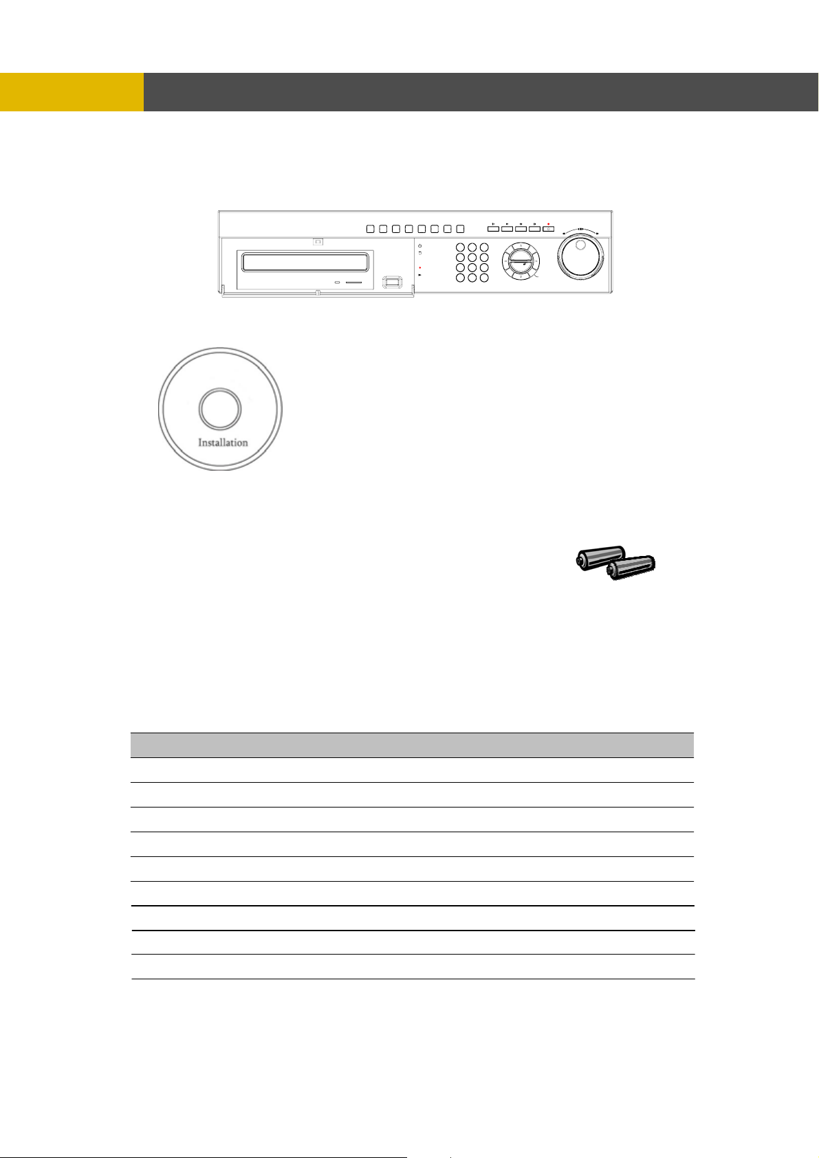
3.1 FRONT PANEL CONTROLS
1 SPOT / ESC Button to control spot monitor/ return to the previous menu
2 FUNCTION Using this button when you select “USER” in Relay 4
3 AUTO / F / ( - ) Button to begin the auto sequence mode/ decrease the value/ focus in PTZ mode
4 LED Display
5 PTZ Button to control PTZ camera
6 SEARCH(PRESET) Button to display the search menu/ preset in PTZ mode
7 LV / PB Button to convert the screen into real view mode or into playback mode
8 SLOW( ) Button to slow down the playback speed
9 FAST( ff ) Button to speed up the playback speed
10 DIRECTION( ef )
11 PLAY / PAUSE( ) Button to start the playback. If press again, a still picture is displayed during
12 REC( ) Button to begin and stop recording
13 R.HDD RACK Removable HDD rack (Option: Built-in Removable HDD or CD-RW or DVD±RW)
14 USB port USB 2.0 port to use a USB memory stick, Mouse or USB external devices
15 FREEZE / F / ( + ) Button freeze image/ increase the value/ focus in PTZ mode
16 COPY(AF) Button to display the copy menu/ automatically focus in PTZ mode
17 CHANNEL SELECT Buttons to select the camera or input the password
18 MULTI Multi-channel select button
19 ALARM RESET / § Button to release the event signal/ move the left direction/ PAN left in PTZ mode
20 «/ STATUS / ( HOME ) Button to enter the next step/ display the status/ return to home position in PTZ mode
21 PIP / ª Button to control PIP function/ move to the lower direction/ TILT down in PTZ mode
22 D-ZOOM / ¨ Button to control the digital zoom/ move to the right direction/ PAN right in PTZ mode
23 MENU / © Button to display the setup menu/ move to the upper direction/ TIL T up in PTZ mode
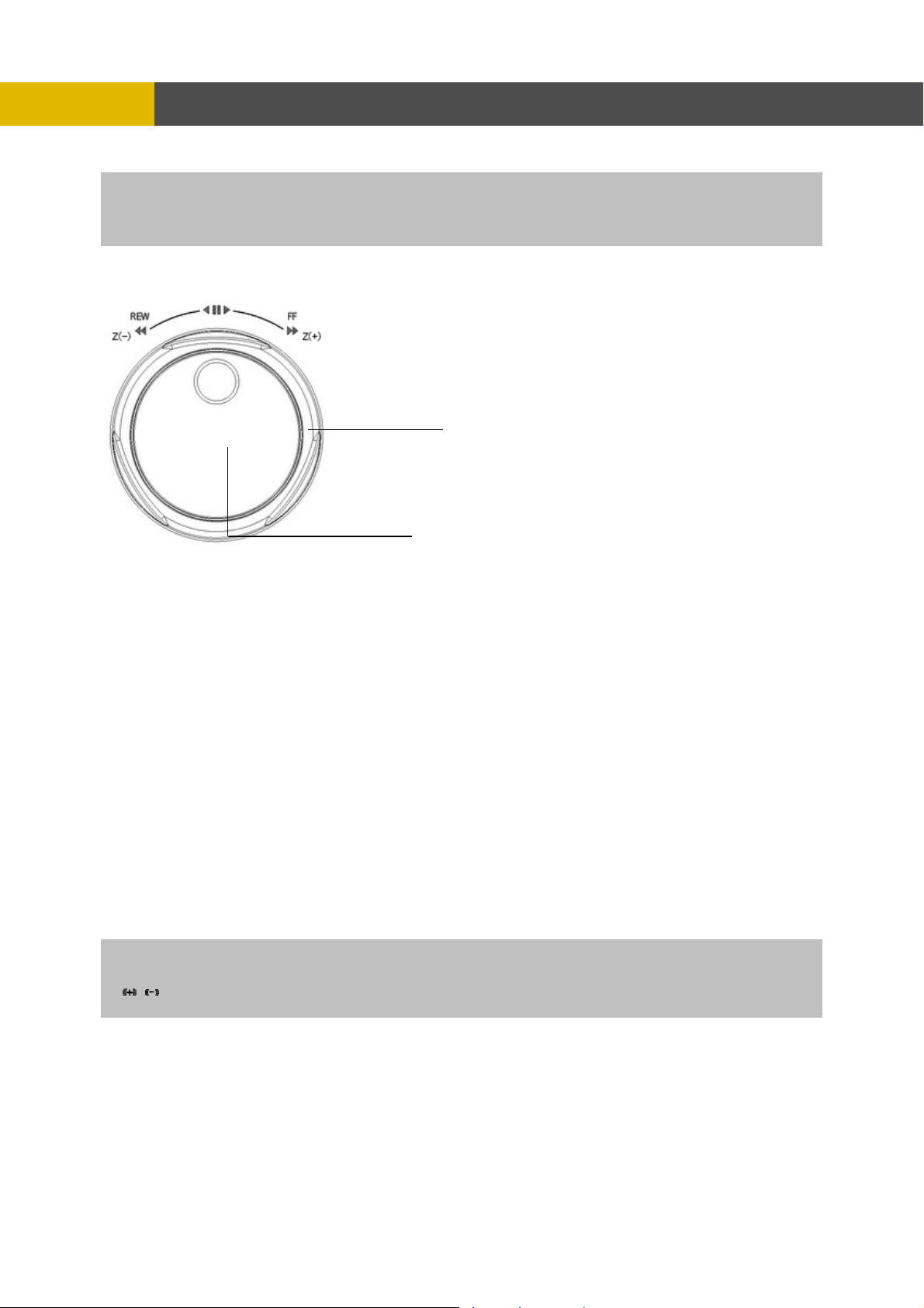
24 JOG SHUTTLE
Display of the status of power(STANDBY), HDD(HDD) , network(RX / T X),REC,P
LAY(PLAYBACK)
Button to release the event signal/ move the left direction/ PAN left in PTZ
mode
playback.
To make easy search in playback and menu setup/ control the playbac k speed/
control the zoom of PTZ camera
7
Page 9
LOCATION AND CONTROL
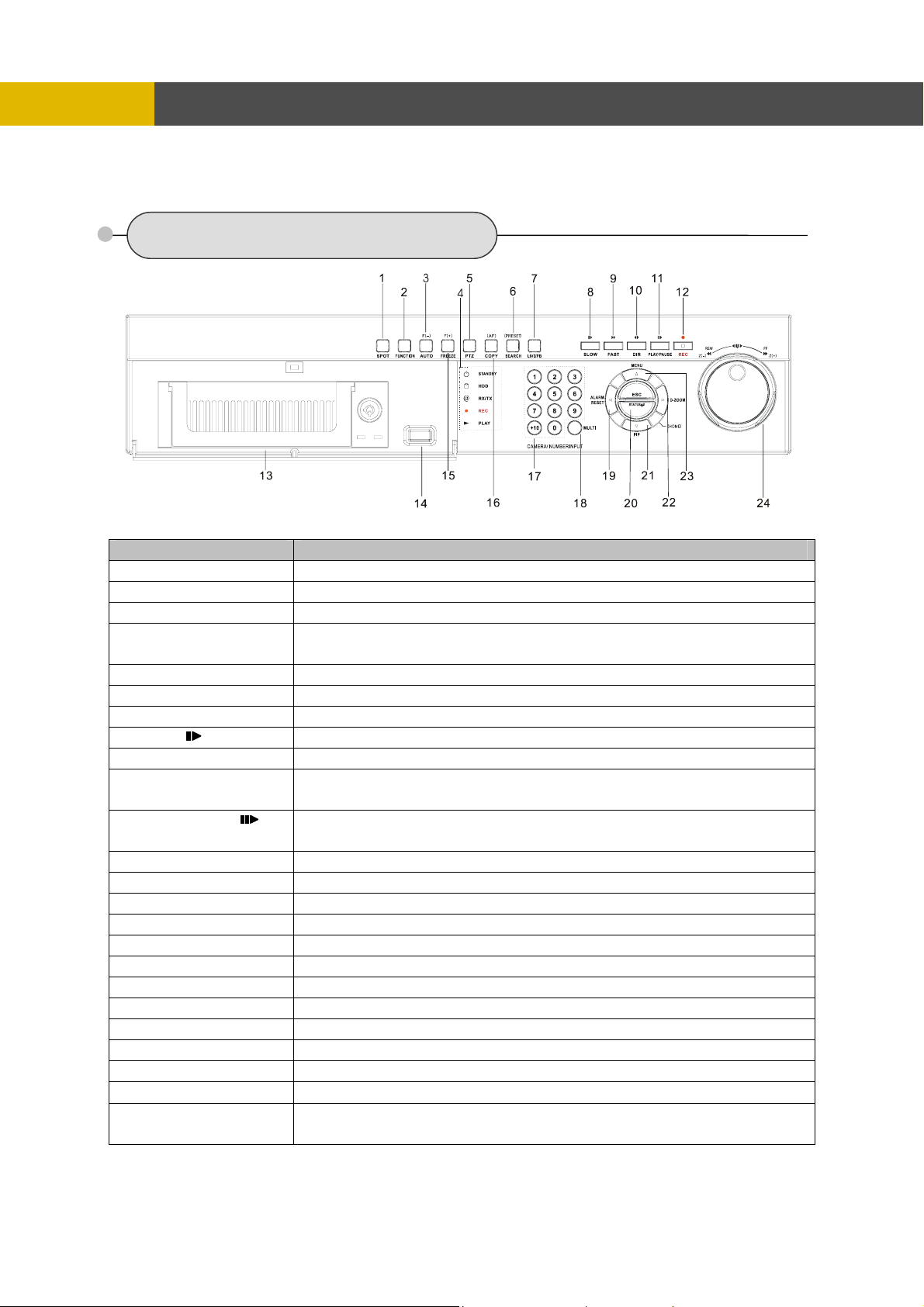
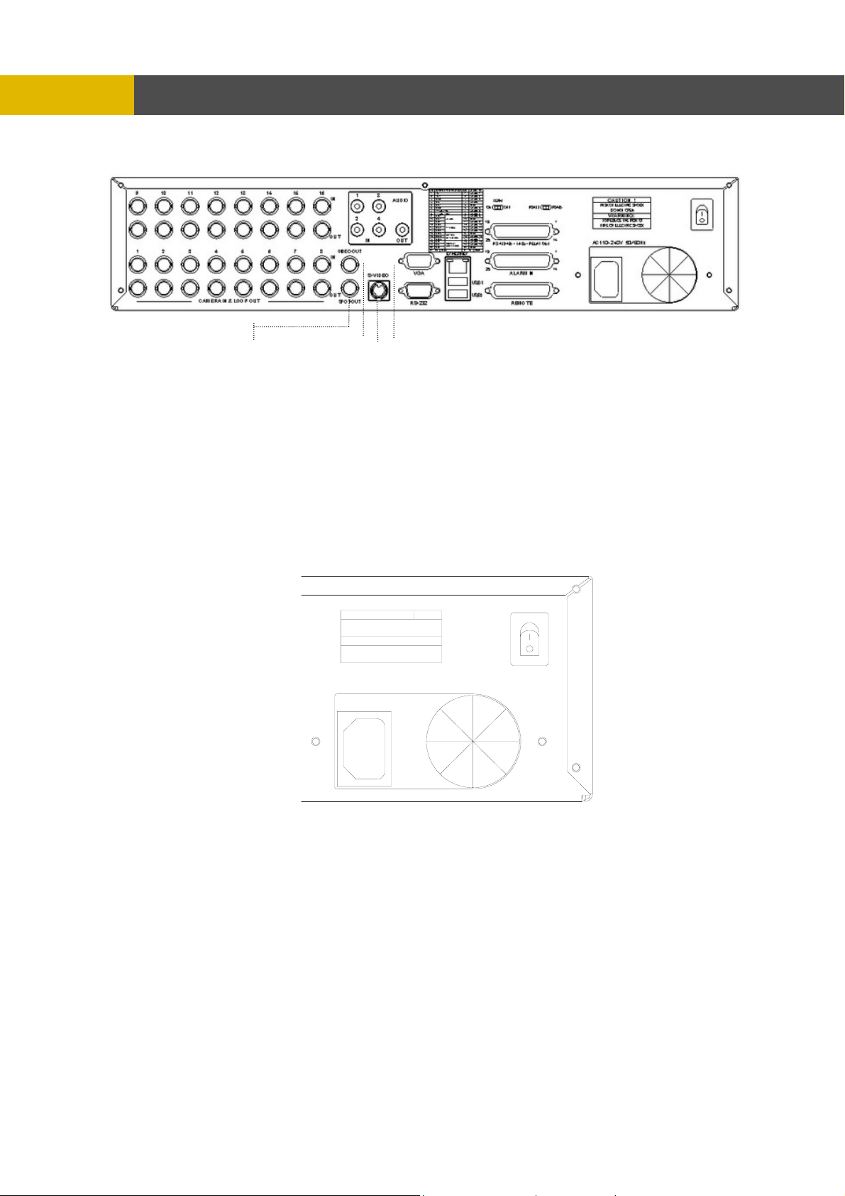
3.2 REAR PANEL CONNECTORS
Port Name Description
1 CAMERA IN
2 AUDIO IN
3 AUDIO OUT
4 TERM ON / OFF
5 T-ADJ
6 RS-422 / 485
7 422 / 485
8 RELAY OUT 4 relay output terminal blocks
9 POWER
10 CAMERA OUT
11 SPOT OUT
12 VIDEO OUT(Option)
13 S-VIDEO OUT
14 SERIAL
15 VGA OUT
16 ETHERNET
17 USB1 / USB2
18 REMOTE Reserved
19 ALARM IN
20 POWER IN
BNC input ports for cameras
RCA input ports for an audio signal(4CH Line input)
RCA output port for an audio signal
Switch to use the terminal block connectors of RS-422 or RS-485
Input and output terminal blocks for time synchronization among DVR
Terminal blocs of RS-422 or RS-485
Switch to convert into RS-422 or RS-485
POWER ON/OFF
BNC output(looping) ports for cameras
BNC input port for spot monitor(Not used in all DVR models)
BNC output port for the main monitor
(Same as the RCA video output of the front panel)
Connector for debugging. This DVR can be controlled by the other device
through this connector(RS-232C).
Input and output terminal blocks for time synchronization among DVRs
Output port for the VGA monitor
This DVR is compatible with TFT LCD monitor in PAL mode.
Port for 10/ 100Mbps Ethernet/ xDSL
USB 2.0 ports to use USB memory stick, Mouse or the external devices
Input terminal blocks for alarm signals
Socket for a 220/ 110VAC power cord
8
Page 10

INSTALLATION
Chapter 4 Installation
4.1 TOTAL CONNECTION LAY-OUT
9
Page 11

INSTALLATION
4.2 INDIVIDUAL CONNECTION
4.2.1 Camera
* Connect a female BNC connector of each camera to a male BNC connector, “CAMERA IN” port.
* Connect the looping BNC output to other inputs as required.
10
Page 12

INSTALLATION
4.2.2 Audio (*Refer to the specification)
Audio Input
- AUDIO IN : Connect the RCA Line Jack of the relevant equipment (for example, a camera with
a built-in microphone) to the AUDIO IN port.
Audio Output
- AUDIO OUT : Connect the RCA Line output to a monitor with a built-in speaker.
NOTE
This DVR can be connected only with a line audio and not support a microphone for audio input and output.
To record audio should be enable in the AUDIO setup at the MENU setup.
As the audio is linked to a camera, it is required that linked camera viewed, either in multi-screen view during
playback to hear the audio.
11
Page 13
INSTALLATION
4.2.3 Monitor
- Connect the female BNC for monitor output.
- Connect the male Y/C cable socket for S-VID
EO monitor output.
.2.4 Power
4
CAUTION
RISK OF ELECTRIC SHOCK
DO NOT OPEN
WARNING:
TO REDUCE THE RISK OF
FIRE OR ELECTRIC SHOCK
AC110~240V 50/ 60 Hz
- Auto-detect the correct voltage of power (110~240 VAC)
- Connect the power cord.
12
Page 14

4.2.5 USB 2.0 ports
1
○
2
○
Installation Process
Connect the desired device to the DVR, as shown above.
( For example, USB memory stick, mouse, external storage device etc.)
Note: 1. Most USB memory stick brands are compatible, problem occurs only to some brands.
2. Most CD-RW disks are compatible using CD-RW device, problem occurs only to some
INSTALLATION
Three USB ports are provided to connect a USB memory stick, external storage devices and
CD-RW/DVD-RW for video clip copying. One USB port is on the front panel and the other two
are on the rear panel.
A USB mouse can be connected to one of the ports. You can use the mouse to navigate
through the screens and menus much like you would on a computer.
Therefore, when data is unable to be achieved from the USB memory stick, please try
again using other brands.
brands. Therefore, when data is unable to be achieved from the CD-RW DVR, please try
again using other brand CD-RW disks.
3. When compatibility problem occurs using DVD-RW device, please try again using other
brand DVD-RW disks (CDs not supported: DVD-R, DVD+R, and DVD+RW).
13
Page 15

OPERATION
Chapter 5 Operation
5.1 FACTORY DEFAULT
MENU Setup>
QUICK SETUP>
QUICK SETUP…………………………..………OFF
IMAGE SIZE………………………………………720x240
RECORD FRAME…………………………………60
EVENT……………………….…..…………...........ALL
PRE RECORD TIME……….……………………..5 sec
POST RECORD TIME………………………..…..10 sec
IMAGE QUALITY.. ………………………………FINE
AUDIO RECORD ………………………………….OFF
REMOTE CONTROL ID.…………….………..… ..ALL
SCREEN>
POSITION
HORIZONTAL POSITION………………….0
VERTICAL POSITION.……………………..0
AUTO SEQUENCE
QUAD-A~E/ SIX/ SEVEN/ NINE-A~B/
TEN/ THIRTEEN/ SIXTEEN.…….. ……...3SEC
ADD AUTO SINGLE….…………………...OFF
AUTO-SINGLE CH1~16………………..…3SEC
DISPLAY
HDD FREE SPACE.………………………..ON
HDD FREE SPACE MODE..…...………….PERCENT
RECORD STATUS..…..…………………...ON
CLOCK DISPLAY…….………………….…ON
DATE & TIME MODE..………………….….NUMBER
TITLE DISPLAY………………………….….ON
TITLE MODE…..……………………….…...TEXT
BORDER COLOR.…………………….……WHITE
REMOTE CONTROL ID..…………….……OFF
SPOT DISPLAY……………………….…….ON
TITLE
CH 1~CH 16………………………………....CH 1~CH16
MULTI SCREEN
LIVE 4E………………………………… ....2/ 4/ 6/ 8
LIVE 7……………………………………….1/ 2/ 3/ 4/ 5/ 6/ 7
LIVE 9B………………………………… ....10/11/12/13/14/15/16/1/2
LIVE 10………………………………………1/ 2/ 3/ 4/ 5/ 6/ 7/ 8/ 9/ 10
LIVE 13………………………………………1/ 2/ 3/ 4/ 5/ 6/ 7/ 8/ 9/ 10/ 11/ 12/ 13
COVERT
CH 1~16……………………………………....OFF
SELECT…………………………………..…..LV&PB&NW
SPOT
SPOT MODE……………………………………..MANUAL
SPOT SEQ. TIME….…………………………....3SEC
14
Page 16

ADD SPOT MULTI……………………………....OFF
REC HDD INITIALIZE
BACKUP HDD INITIALIZE
DATE & TIME
INTERNET TIME ADJUST...…………………OFF
DAYLIGHT SAVING TIME..…….………..…..OFF
PASSWORD
MASTER PASSWORD…..…………….……………..11111111
SUPERVISOR PASSWORD.………….……………..22222222
MENU DISPLAY CHECK.……………….……………OFF
POWER OFF CHECK...………………….……………OFF
OPERATION
RECORD>
RECORD SETUP
RECORD PROGRAM..………………….……......6
RECORD PROGRAM (Refer to page 52)
IMAGE QUALITY
RECORD QUALITY……………………….…….....FINE
AUDIO RECORD
AUDIO 1………………..…………………….…...... OFF
AUDIO 2………………..…………………….…...... OFF
AUDIO 3………………..…………………….…...... OFF
AUDIO 4……………..……………………….…...... OFF
REPEAT RECORD
REPEAT RECORD..………………………………..ON
REPEAT RECORD ALARM.…………………..…..5%
PLAY MODE.…………………………………….……........FRAME
BACKUP MODE..……………………………….……........OFF
HOLIDAY
HOLIDAY RECORD…………………………….….OFF
HOLIDAY SETUP(MM/DD) ………………………..00/00
EVENT>
MOTION DETECTION
CHANNEL……………………………………..1
SENSITIVITY………………………………….5
AREA SETUP
TEST MOTION
EVENT SCREEN MODE………………………….…SCREEN HOLD
EVENT CHECK.………………………………………OFF
EVENT MESSAGE..………………………………....OFF
EVENT MESSAGE RESET……………………..…..5SEC
EVENT BUZZER..……………………………….…...OFF
SENSOR INPUT
SENSOR 01~16 INPUT TYPE..……………..NOT USED
RELAY OUTPUT
CH 1~16: ALARM/ V-LOSS/ MOTION..….…1/ 2/ 3
RELAY 1~3 OUTPUT TIME..…………………1SEC
RELAY 4 SELECT.….…………………………POWER
SYSTEM>
HDD
HDD CONFIGURATION
REMOVABLE/ FIXED-01~04……..……….….NO HDD
CLOCK
TIME ADJUST
15
Page 17

REC/PLAY CHECK…..………………….……………....…OFF
VIDEO STANDARD…………….…………………………..AUTO
LANGUAGE……………….………..………………….…….ENGLISH
REMOTE CONTROL ID.…………….………..…………….ALL
KEY ECHO…..………………….……………………………ON
DVR INITIALIZE.………………….………..………………..NO
FIRMWARE UPGRADE………………….…………………NO
RS-422/485
SYSTEM ID……..…………………………………….1
OUTPUT MODE.…………………………………….RS-485
CH 1~16: MODEL/ ID….………………….…….... NONE/ 9600/ 1
E-mail
EVENT SEARCH
BLOCK SEARCH
FILE SEARCH
MEDIA………………………………………………...USB_FRONT
BOOKMARK SEARCH
LOG FILE SEARCH
COPY
COPY START/ END/ CUR TIME.…………………2000/00/00 00:00:00
MEDIA FORMAT
FORMAT MEDIA..…………………………………..USB_FRONT
OPERATION
LINK>
NETWORK
DHCP……..……………………………………………OFF
RS-232
BAUD RATE..………………….……………………..115200
DATA BIT……..……………………………………….8
PARITY BIT….……..…………………………………NONE
STOP BIT……..……………………………………….1
BAUD RATE..………………….……………………..115200
DATA BIT……..……………………………………….8
PARITY BIT….……..…………………………………NONE
STOP BIT……..……………………………………….1
PTZ
SEARCH>
CALENDAR SEARCH
HDD ID………………………………………………..NORMAL
CHANNEL…………………..………………….…….ALL
SEARCH & COPY
HDD ID………………………………………………..NORMAL
CHANNEL…………………..………………….…….ALL
TIME SEARCH
HDD ID………………………………………………..NORMAL
CHANNEL…………………..………………….…….ALL
HDD ID………………………………………………..NORMAL
CHANNEL…………………..………………………..ALL
EVENT…………………..……………………………ALL
HDD ID………………………………………………..NORMAL
COPY>
COPY STATUS
EXIT> ………………………………………………………....SAVE ONLY
………………………………………………………....SAVE AND EXIT
………………………………………………………....EXIT WITHOUT SAVE
16
Page 18
OPERATION
5.2 FRONT PANEL CONTROLS
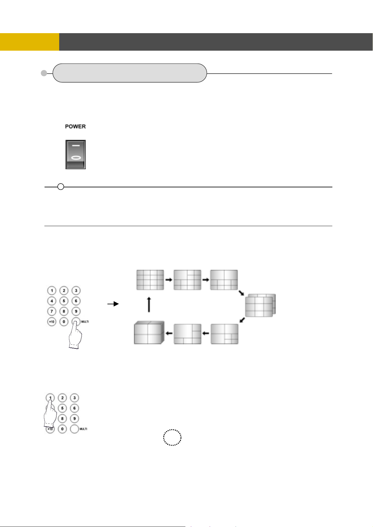
5.2.1 POWER ON/ OFF SWITCH(located in rear panel)
After the connection of power cord and other devices(HDDS) with this DVR, turn the power on.
a. The video signal system (NTSC or PAL) is automatically
detected.
b. Power Failure Recovery
This DVR automatically reverts back to programmed record
parameters upon power restoration.
c. If the power key is protected by password, the power on/off
cannot be executed before input the correct password.
(Refer to the PASSWORD in the SYSTEM menu).
• If there is no video signal, the video signal system is set to NTSC. Do not input the PAL type video signal or it may
cause the DVR’s malfunction. In this case, turn off and on again.
5.2.2 SCREEN DISPLAY
5.2.2.1 Multi-Display & Full Screen display
a. Multi display
The example is display by 16CH DVR
To change a single camera display to the multi camera, press the MULTI button.
b. Full screen display
Press the desired camera number button to display on the monitor.
17
Page 19
OPERATION
Use the +10 Button when you select two digit camera numbers.
EX) Camera Number 12 = Press the +10 Button, and then press the No. 2 Button.
CAMERA/NUMBER INPUT buttons are used to input the password in the password lock function.
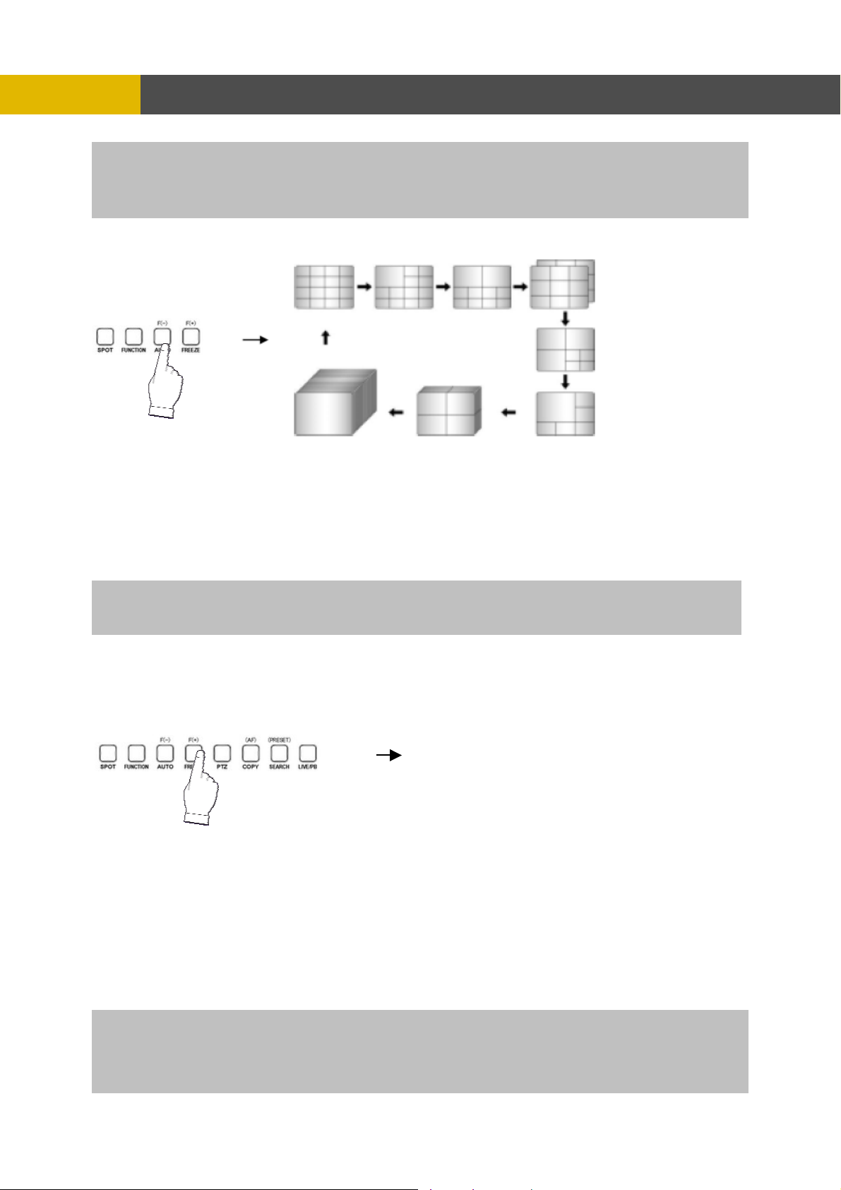
5.2.2.2 Auto Sequence Display
<ADD AUTO SINGLE : ON> example for 16CH
- Press the AUTO button, each screen display will be automatically switching
according to the
AUTO SEQUENCE setup.
- OFF” in the AUTO SEQUENCE setup menu, the single
If you set up “ADD AUTO SINGLE :
display will be skipped.
- ay, set up “ADD AUTO SINGLE : ON” in the AUTO SEQUENCE setup
To view the single displ
menu and the single display will be included in the auto sequence display.
-
Press the AUTO button again to exit the AUTO mode.
If an event t
Please refer to the AUTO SEQUENCE of Chapter 6 MENU setup for mo
akes place, the AUTO SEQUENCE mode will be cancelled.
re information.(Page 40)
.2.2.3 Freeze
5
MULTI SCREEN MODE
At the Multi display mod
e, press the FREEZE button and then select the desired camera
number.
Press the F
REEZE button again to release the FREEZE mode.
INGLE SCREEN MODE
S
Press the FREEZE button af
ter the desired channel is selected.
Press the FREEZE button again to release the FREEZE mode.
- If you press the MULTI button after pressing the FREEZE button, all the channels will display
still images.
- FREEZE function is not available, when auto mode is selected.
formation) (Refer to AUTO SEQUENCE in the SCREEN menu for further in
18
Page 20
OPERATION
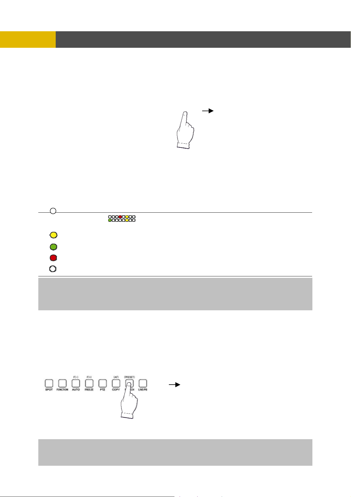
5.2.3 RECORD
Press the REC button and the following message will be displayed as below;
MANUAL MODE
Press the REC button to begin recording.
To stop recording, press the REC button again. The screen will be turned into real time display
mode.
SCHEDULE MODE
When Schedule mode is selected, the recording will be automatically executed according to the
recording schedule. (Please refer to the RECORD PROGRAM in the RECORD setup, page 47.)
The color of record indication ( ) on the screen will be changed according to the type of
recording and refer to the following.
- “ (Yellow) ” : Manual recording status.
- “ (Green) ” : Schedule recording status.
- “ (Red) ” : Event recording status. (Motion detection/ Video loss/ Sensor)
- “ (White) ” : Not recording.
All channels will be displayed by red lights even if an event happened just on one channel. Red light will be
displayed because this unit enters the event record mode when event happened. If a channel has an event,
all channels will be recorded by event recording frame rate to be set in RECORD PROGRAM menu.
5.2.4 SEARCH & PLAYBACK
Press the SEARCH button, the SEARCH menu screen appears.
TIME SEARCH
If you press the PLAY button in the real time screen mode, playback will be executed from the end of
the previous time search and press the desired channel select button.
To exit the playback mode and see the live screen again, press LV/PB button.
19
Page 21

-
5.2.4.1 CALENDAR SEARCH
At the SEARCH menu;
① Move the cursor to CALENDAR SEARCH using © or ª button.
② Press the ENTER button and CALENDAR SEARCH screen appears.
OPERATION
③ Select the desired HDD ID using the (-) or (+) button.
④ Move the cursor to CHANNEL using the © or ª button and select the desired channel using the
(-) or (+) button.
⑤ Move the cursor to the desired position using the © , ª , § , ¨ buttons, and then select the
desired date.
⑥ Press the ENTER button, and the following screen appears.
⑦ Move the cursor to the desired position of during HOUR, MIN and SEC using the © , ª , § , ¨
buttons, and select the desired time using the (-), (+) buttons.
⑧ Press the ESC button to exit this menu.
20
Page 22

-
5.2.4.2 SEARCH & COPY
At the SEARCH menu;
① Move the cursor to SEARCH & COPY using © or ª button.
② Press the ENTER button and SEARCH & COPY screen appears.
OPERATION
③ Select the desired HDD ID using the (-) or (+) button.
④ Move the cursor to CHANNEL using the © or ª button and select the desired channel using the
(-) or (+) button.
⑤ Move the cursor to the desired position of SEARCH TIME using the © , ª , § , ¨ buttons, and
then set up the desired time using the(-), (+) buttons or turn the wheel scroll of mouse to set the
search time.
⑥ Press the ENTER button and you can playback.
⑦ Move the cursor to START COPY and then press the ENTER button to copy.
⑧ Press the ESC button to exit this menu.
5.2.4.3 TIME SEARCH
At the SEARCH menu;
① Move the cursor to TIME SEARCH using © or ª button.
② Press the ENTER button and TIME SEARCH screen appears.
③ Select the desired HDD ID using the (-) or (+) button.
④ Move the cursor to CHANNEL using the © or ª button and select the desired channel using the
(-) or (+) button.
⑤ Move the cursor to the desired position of SEARCH TIME using the © , ª , § , ¨ buttons, and
then set up the desired time using the(-), (+) buttons or turn the wheel scroll of mouse to set the
search time.
⑥ Press the ENTER button and you can playback.
⑦ Press the ESC button to exit this menu.
21
Page 23

-
OPERATION
5.2.4.4 EVENT SEARCH
At the SEARCH menu;
① Move the cursor to EVENT SEARCH using © or ª button.
② Press the ENTER button and the EVENT SEARCH menu screen appears.
③ Select the desired HDD ID using the (-) or (+) button.
④ Move the cursor to CHANNEL using the © or ª button and select the desired channel using the
(-) or (+) button.
⑤ Move the cursor to EVENT using the © or ª button and select the event type to search using the
(-) or (+) button.
⑥ Move the cursor to the desired position of SEARCH TIME using the © , ª , § , ¨ buttons, and
then set up the desired time using the(-), (+) buttons.
(Or turn the wheel scroll of mouse to search the event list.)
⑦ Press the ENTER button or turn the wheel scroll of mouse, and the event list searched appears.
⑧ When the event list appears on the screen, select the desired list using © or ª buttons or wheel
scroll of mouse and press the ENTER button for the playback.
- When video loss is detected, up to five seconds of pre-recording data is stored on the HDD and the details
will be listed in the EVENT LIST. The beep sounds and the LED of the ALARM RESET button will flicker.
Press the ALARM RESET button to remove this signal.
- When the unit receives a signal from the sensor input, DVR begins to record the input data according
to the PRE/POST TIME in the RECORD setup and the details will be listed in the EVENT LIST.
CAUTION
ⓐ If the internal HDD(s) is initialized, all of the event images will be deleted.
ⓑ When the unit is in normal recording status, the pre-recording will not be executed.
5.2.4.5 BLOCK SEARCH
At the SEARCH menu;
① Move the cursor to BLOCK SEARCH using © or ª button.
② Press the ENTER button and the BLOCK SEARCH menu screen appears.
22
Page 24

-
③ Select the desired HDD ID using the (-) or (+) button.
④ Move the cursor to the desired position of SEARCH TIME using the © , ª , § , ¨ buttons, and
⑤ Press the ENTER or turn the wheel scroll of mouse, and the list searched appears.
⑥ When the list appears on the screen, select the desired list using © or ª buttons or wheel scroll
5.2.4.6 FILE SEARCH
At the SEARCH menu;
① Move the cursor to FILE SEARCH using © or ª button.
② Press the ENTER button and the FILE SEARCH screen appears.
OPERATION
then set up the desired time using the(-), (+) buttons. (Or turn the wheel scroll of mouse to search
the block list.)
of mouse and press the ENTER button for the playback.
③ Select the desired type of MEDIA using the (-) or (+) button.
④ Press the ENTER button or turn the wheel scroll of mouse, an
⑤ When the list appears on the screen, select the desired list using © or ª buttons or wheel s
of mouse.
⑥ TER button for the playback.
Press the EN
.2
.4.7 BOOKMARK SEARCH 5
At the SEARCH menu;
OOKMAR① Move the cursor to B
② Press the ENTER button and the BOOKMARK SEARCH screen a
K SEARCH using © or ª button.
d the list searched appears.
ppears.
croll
23
Page 25

-
Press the ENTER button, and the list searched appears.
③
When the list appears on the screen, select the desired list using © or ª buttons or wheel scroll
④
⑤ Press the ENTER button for the playback.
<H e Bookmark list>
① Press the “PB/PAUSE” button to playback.
② Find the desired image using s
③ Press the “PB/PAUSE” button to see the stil
④ Press the “PTZ” button to add the BOOKM
5.2.4.8 LOG FILE SEARCH
t the SEARCH menu;
A
① Move the cursor to LOG FIL
② Press the ENTER bu
OPERATION
of mouse
ow to mak
huttle ring.
l picture of the desired image.
ARK list.
E SEARCH using © or ª button.
tton and the LOG FILE SEARCH screen appears.
③ Move the cursor to the desired position of SEARCH TIME using the © , ª , § , ¨ buttons, and
then set up the desired time using the(-), (+) buttons.
(Or turn the wheel scroll of mouse to search the desired list.)
④ use, and the list searched appears.
Press the ENTER button or turn the wheel scroll of mo
⑤ ing © or ª buttons or the wheel
When the list appears on the screen, select the desired list us
scroll of mouse.
24
Page 26

-
OPERATION
5.2.5 SEARCH BUTTON INFORMATION
○
1
.1.5.1 SLOW ( )
5
Press this button to make th
the upper left side of screen as below;
(If you press this button again, the playb
speed level)
i. 1/2 - 2
times slower than normal playback speed
ii. 1/4 - 4 times slower than normal playback speed
iii. 1/8 - 8 times slower than normal playback speed
iv. 1/16 - 16 times slower than normal playback speed
v. 1/32 - 32 times slower than normal playback speed
vi. 1/64 - 64 times slower than normal playback speed
vii. 1/128 - 128 times slower than normal playback spee
.2 PLAY / PAUSE ( )
5 .5.2
Press this button to begin playback at n
Press this button again to pause the playback.
NOTE
ress the “PLAY/ PAUSE” button to playback, it will playback from the end of played final image. If you p
How to playback a section repeatedly>
<
① Press the “AUTO” button to set up the A
upper right of the screen.
② ZE” button to set up the B position(ending position) and “(A-B)” will be
And then press the “FREE
displayed on upper right of the screen and played between A to B repeatedly.
How to release the section repetition playback>
<
Press the “PIP(CLEAR)” button and section repetition
.2.5.3 FAST ( ) 5
Press this button to mak
displayed at the upper left side of screen as below:
i. 2 - 2 times faster than normal playback speed
ii. 4 - 4 times faster than normal playback speed
iii. 8 - 8 times faster than normal playback speed
iv. 16 - 16 times faster than normal playback speed
v. 32 - 32 times faster than normal playback speed
vi. 64 - 64 times faster than normal playback speed
vii. 128 - 128 times faster than normal playback speed
(However much data may be recorded can be searched in 3
.2.5.4 DIRECTION ( ) 5
Press this button to change direct
○
2
○
3
○
4
e speed level which is slower than normal speed (X1) and displayed it at
ack speed will be changed in the order of the below seven
d
ormal speed (X1).
position(starting position) and “(A- )” will be displayed on
playback will cancel.
e faster the speed level which is higher than normal speed (X1) and
seconds)
ion to forward ( X ) or backward ( W ) in playback mode.
25
Page 27
-
OPERATION
NOTE
Press DIR
during the real time display mode (Instant Playback).
button to make a reversed playback from the end of recorded or played images
.2.6 JOG SHUTTLE INFORMATION
5
.2.6.1 Normal Playback Mode
5
① Turn the SHUTTLE ring to the d
esired playback direction and speed level according to the above
drawing during the playback.
② mode when the SHUTTLE ring is returned to the center position.
The DVR will go back to pause
5.2.6.2
① Press the PB/PAUSE button to get a still
② Turn the
Frame by Frame Playback Mode
image while the DVR is in the playback mode.
JOG DIAL in either direction continuously for playback of consecutive frames.
③ Press the PB/ PAUSE button again to return to the previous mode.
.2.6.3 Digital Zoom of PTZ camera
5
① Select a pre-set single camera, and t
hen press the PTZ button.
② Turn the SHUTTLE RING to zoom in or out.
③ Turn the SHUTTLE RING to iris close/open o
.2.6.4 Using the JOG DIAL in the MENU setup
5
① Turn the JOG DIAL to modify the displayed setup
② Turn the shuttle ring to set up the “SCHEDULE” in RECORD SETUP of th
TE Not All Functions can used by JOG DIAL
NO
In the MENU setup, below buttons can be used
: Press this button to modify the setup value.
SHUTTLE RING
JOG DIAL
f PTZ.
value in MENU setup.
instead of the JOG DIAL.
e MENU setup.
26
Page 28
-
OPERATION
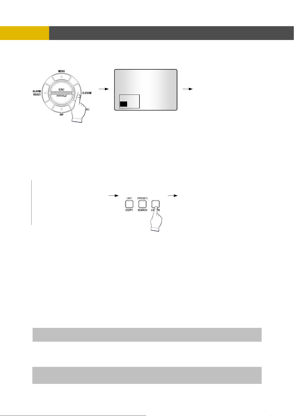
5.2.7 DIGITAL ZOOM
Press the desired camera number button you wish to display on the monitor.
①
② Press the D-ZOOM button. The indication screen appears on the main screen.
③ Turn wheel scroll of mouse or press the © , ª , § , ¨ buttons to select the desi
④ Press the ENTER button to change the zoom x2 ~ x4.
⑤ Press the ESC button to exit this screen.
CH1
.2.8 SCREEN SELECT(LV/PB)
5
► PLAY CH1
uring the playback, press the LV/PB button to convert the screen into real time display mode.
D
(Press this button again to return to the playback mode.)
.2.9 SPOT MONITOR
5
Set up the desired mode in “SPOT” of “SCREEN MENU” before executing the SPOT mode.
5.2.9.1 MANUAL MODE
① Press the “SPOT” button
② Press a camera button to display that camera on the spot monitor.
③ OSD of the selected channel will be indicated at the upper left of sc
5.2.9.2 EVENT MODE
Press the “SPOT” button a
NOTE: If you press the “SPOT” button after setting this mode, you can control the spot monitor manually.
5.2.9.3 SEQUENCE MODE
Press the “SPOT” button and ea
in sequence.
NOTE: If you press the “SPOT” button after setting this mode, you can control the spot monitor manually.
4CH version don’t have this function.
on the front panel to toggle “SPOT” mode indicated on the main monitor.
reen in live mode.
nd the Spot monitor will display the channel which an event happened.
ch channel and split channel will be displayed on the Spot monitor
red location.
27
Page 29

-
OPERATION
** Please refer to 6.2.7 SPOT of SCREEN
.2
5 .10 COPY
Press the COPY button to copy the recorded images into other media and the COPY MENU screen
appears.
.2.10.1 COPY
5
.2.10.1-1 COPY TO EXTERNAL HDD (USB)
5
At the COPY menu,
① Move the cursor t
② Press the ENTER button and the following screen app
Select the desired MEDIA(USB port 3 select the correct USB position for HDD) (-), (+) buttons ③
or wheel scroll of mouse.
28
o COPY using the © or ª buttons.
ears.
Page 30

-
OPERATION
④ using the © or ª buttons and select the desired HDD to copy among
Move the cursor to HDD ID
HDD IDs using the (-), (+) buttons or wheel scroll of mouse.
⑤ E/ COPY END TIME using the © ,
Move the cursor to the desired position of COPY START TIM
ª , § , ¨ buttons and press the (-) or (+) button to set up the time to set up the COPY START
TIME and COPY END TIME.
** S g to the right to move the cursor of COPY END TIME or to the left
croll bar: - Turn the shuttle rin
to move the cursor of COPY START TIME and the cursor will be yellow. And then turn the wheel
scroll of mouse to move the cursor to the desired time.
- I
t can operate with just Mouse click.
⑥ Press the ENTER button to copy.
TE
NO
When th
the monitor. You can search and playback the copied images in HDD with DVR itself
(Please refer to 5.2.4.6 FILE SEARCH, page 23.)
** You have to format in case of the media to be
e copy is in process, the copying status(ex. “COPY 30%”) will be displayed on the right side of
used in DVR for the first time.
.2.10.1-2 COPY TO USB memory stick
5
At the COPY menu,
① Move the cursor t
② Press the ENTER button and the following screen app
o COPY using the © or ª buttons.
ears.
Select the desired MEDIA(select three of USB port) (-), (+) buttons or wheel scroll of mouse.
③
④ Move the cursor to HDD ID using the © or ª buttons and select the desired HDD to copy am
ong
HDD IDs using the (-), (+) buttons or wheel scroll of mouse.
⑤ E/ COPY END TIME using the © ,
Move the cursor to the desired position of COPY START TIM
ª , § , ¨ buttons and press the (-) or (+) button to set up the time or turn the wheel scroll of
mouse to set up the COPY START TIME and COPY END TIME.
29
Page 31

** Scroll bar: - Turn the shuttle ring to the right to move the cursor of COPY END TIME or to the left
- It can operate with just Mouse click.
⑥ Press the ENTER button to copy.
5.2.10.1-3 COPY TO CD-RW/ DVD-RW
OPERATION
to move the cursor of COPY START TIME and the cursor will be yellow. And then
turn the wheel scroll of mouse to move the cursor to the desired time.
When the copy is in process, the copying status(ex. “COPY 30%”) will be displayed on the right side
of the monitor.
You can search and playback the copied images in USB stick memory with DVR itself as well as PC.
(Please refer to 5.2.4.6 FILE SEARCH, page 23.)
At the COPY menu,
① Move the cursor to COPY using the © or ª buttons.
② Press the ENTER button and the following screen appears.
③ Select the desired MEDIA(CD-RW/DVD) (-), (+) buttons or wheel scroll of mouse.
④ Move the cursor to HDD ID using the © or ª buttons and select the desired HDD to copy among
HDD IDs using the (-), (+) buttons or wheel scroll of mouse.
⑤ Move the cursor to the desired position of COPY START TIME/ COPY END TIME using the © ,
ª , § , ¨ buttons and press the (-) or (+) button to set up the time or turn the wheel scroll of
mouse to set up the COPY START TIME and COPY END TIME.
** Scroll bar: - Turn the shuttle ring to the right to move the cursor of COPY END TIME or to the left
to move the cursor of COPY START TIME and the cursor will be yellow. And then
turn the wheel scroll of mouse to move the cursor to the desired time.
- It can operate with just Mouse click.
⑥ Press the ENTER button to copy.
30
Page 32

OPERATION
When the copy is in process, the copying status(ex. “COPY 30%”) will be displayed on the right side of
the monitor.
NOTE
- CD-RW or DVD-RW is option and this DVR need the interface board to install a built-in CD-RW or
DVD-RW.
- If you want a built-in CD-RW or DVD-RW, must purchase it from a authorized dealer.
- You can search and playback the copied images in CD or DVD with DVR itself as well as PC.
(Please refer to 5.2.4.6 FILE SEARCH, page 23.)
** You have to format in case of the media to be used in DVR for the first time.
5.2.10.1-4 STOPPING COPY
Press the COPY button to stop copying and the following screen appears.
Move the cursor using the © or ª buttons and
select “YES” or “NO” and then press the ENTER button.
5.2.10.2 COPY STATUS
At the COPY menu,
① Move the cursor to COPY STATUS using the © or ª buttons.
② Press the ENTER button to see the current copying status and the following screen appears.
③ Press the ESC button to exit this menu.
CUR TIME : Indicate current copying situation among the total copying data.
31
Page 33

5.2.10.3 MEDIA FORMAT
At the COPY menu,
① Move the cursor to MEDIA FORMAT using the © or ª buttons.
② Press the ENTER button and the following screen appears.
③ Select formatting media using the (-), (+) button.
④ Move the cursor to MEDIA FORMAT and then press the “ENTER” button.
⑤ The message, “FORMATTING” will be displayed while formatting.
OPERATION
NOTE
If you don’t connect any media device, you can see the message, “Fail”.
5.2.11 DVR STATUS
Press the “STATUS” button or double-click the left button of Mouse, The SYSTEM INFOMATION
screen will appear. To see the next page, press the § , ¨ or use the wheel scroll of Mouse.
Press the STATUS button again to move on next information screen or press the “ESC” button to
exit the menu.
5.2.12 PTZ CONTROL
5.2.12.1 PTZ control in live view
① Press the desired camera button to be displayed and the PTZ channel, model name and ID will
be displayed on the left side of the monitor as the following picture.
32
Page 34

OPERATION
② Press the “PTZ” button to control pan, tilt and zoom functions of PTZ camera.
③ Use the § , ¨ button to pan left and right and the © or ª button to tilt up and down.
④ Turn the SHUTTLE ring to zoom in and out.
⑤ Use the (-) or (+) button to focus. Or press the (AF) button for auto focusing.
⑥ Press the PTZ button again to exit the PTZ mode.
** Please refer to 6.6.4 PTZ setup of LINK menu, page 74.
5.2.12.2 PTZ PRESETTING
① Press the “PTZ” button to enter PTZ mode.
② Press the “PRESET” button to enter PRESET mode and “PTZ(PRESET)MOVE”, OSD will be
displayed on the left side of the monitor.
③ Move to the desired preset location using the “NUMBER” buttons.
④ Press the “PRESET” button again and “PTZ(PRESET)SET”, OSD will be displayed on the left
side of the monitor.
⑤ Make the desired setting of the PTZ camera using the © , ª , § , ¨, (-), (+) buttons.
⑥ Press the “NUMBER” button to set up the revised presetting.
PRESETS
- A preset is a user-defined camera position using pan and tilt, zoom, and focus commands.
This DVR has the Programming capacity for 16 preset locations for 16CH.
This DVR has the Programming capacity for 8 preset locations for 8CH.
This DVR has the Programming capacity for 4 preset locations for 4CH.
- This DVR has RS-422/485 terminal block telemetry port on the rear panel.
33
Page 35

OPERATION
5.2.13 FUNCTION BUTTON
<Audio select >
You can select audio channels regardless of monitoring screen.
Press the “function(audio select)” button and then press the desired number button and you can
hear audio of selected channel regardless of monitoring screen.
< Link of audio and camera >
Press the “function(audio select)” button and then press the “MULTI” button and you can hear audio
of selected camera.
That is to say, you can hear CH 1 audio when viewing CH 1,
CH 2 audio when viewing CH 2,
CH 3 audio when viewing CH 3 and
CH 4 when viewing CH 4.
You need this button to control “USER” mode of RELAY 4 SELECT.
Please refer to 6.4.8 RELAY OUTPUT, page 56.
5.2.14 PIP CONTROL
① Select a single camera in live view, and then press the PIP button and the following screen will
be displayed.
② Select the desired camera that will be displayed on the PIP screen.
③ Press the ENTER button to make the bigger PIP screen and use the © , ª , § , ¨ buttons to
move the position of PIP screen.
④ Press the ESC button to exit this mode.
34
Page 36

○
-
-
OPERATION
5.3 REMOTE CONTROLLER
Button Name Description
○1 FUNCTION
○
○
1
2
○
13
○
14
○2 Z○3 IRIS ○4 COPY
○5 RECORD ( ● )
3
○6 ALARM RESET
15
○
○7 PLAY / PAUSE( )
○8 SLOW ( )
○9 MULTI
○10 ( ▲ )/(MENU)
○11 ( ◀ )
○12 AUTO / ( - ) / F(-)
○13 (PTZ)
○
16
20
○
○
○
○
24
17
22
○
○
○
18
○
19
○
21
○
23
25
4
○
5
○
6
○
7
○
8
9
○
10
○
11
○
12
○
○14 Z+
Refer to 5.2.13 FUNCTION BUTTON
Zoom out of PTZ
Iris close of PTZ
Display the copy menu
Begin and stop recording
Release the event signal
Press this button to begin playback. If
press again during the playback, a still
picture is displayed
Press this button to slow-down playback
speed
Display multi-screen
Move the cursor up to the next line in the
setup menu
Enter setup menu mode
Move the cursor in left direction in the
setup menu.
Frame by Frame(field by field) playback
Auto sequence / Downward value /
Focus control of PTZ
Select the PTZ mode
Zoom in of PTZ
26
○
27
○
○15 IRIS+
○16 SEARCH
○17 LV/PB
○18 DIGITAL ZOOM
○19 DIR ( )
○20 FAST( ▶▶ )
Iris open of PTZ
Display the search menu
Change screen mode
Control of zoom in and out
Change the direction of playback
Press this button to speed-up playback
speed
○21 SPOT / ESC
Enter the spot mode / Return to the
previous mode
○22 ENTER ( )/(HOME)
○23 ( ▶ )
Enter / Go home in PTZ mode
Move the cursor in right direction in the
setup menu.
Frame by Frame(field by field) playback
○24 ( ▼ ) / (PIP)
○25 FREEZE / ( + ) / F(+)
Move the cursor down to the next line /
Enter PIP mode
Freeze / Up-going value /
Focus control of PTZ
○26 CAMERA BUTTONS
○27 REMOTE
CONTROLLER ID
Camera number select button
Please refer to Remote controller ID in the
system setup
35
35
Page 37

-
MENU SETUP
5.4 MOUSE CONTROL
Doubl
○1 Status d
* You n c on the M
* ca ca lick the below keys lick the below keys ENU screen with a moENU screen with a mouse. use.
○
2
○
1
○
3
○1 Status d
○3 Menu dis
○3 Exit
○2 Value ch
○1 Select
You n c on the M
isplay
isplay
play
ange
Double-clicke-click e left button e left button
One-c ight button
ouble-click of thD e right button
urning the whee
T l scroll
of th
of th
lick of the r
k on thDouble-clic e item or icon
36
Page 38

-
NTRANCE OF THE MENU SETUP
E
ress the MENU button for the desired DVR setting.
P
Simply click the desired icon or item in case of using the mouse.
MENU SETUP
Ch tup
apter 6 MENU Se
You can use the mouse instead of buttons on the front panel of DVR.
6.1 QUICK SE
T P U
Press the MENU button and the QUICK SETUP menu appears as the following picture.
This menu is simply used when user want to change just a few important settings.
**
Note: If you select QUICK SETUP setting is “ON”,the DVR System will according to this Setup
Page setting to record the recording data,If you select QUICK SETUP setting is “OFF”, the
DVR System will recording data according to the Record Setup Page setting.
Select the desired item using the © or ª buttons and set up the value using the (-), (+) buttons or
wheel scroll of mouse.
37
Page 39

-
6.1.
Select “ON” or “OFF” using the (-), (+) buttons or wheel scr
setting.
.1.2
6 IMAGE SIZE
elect the desired IMAGE SIZE for recording using the (-), (+) buttons or wheel scroll of mouse.
S
6.1.3
Select the desired frame rate for normal recording using the (-), (+) buttons or wheel scro
All event channels will be recorded by the setting RECORD FRAME/16.
For example, if you set RECORD FRAME to 120, 16 each channel will be recorded by 7 ips.
** Please refer to chapter 6.3 RECORD.
MENU SETUP
1 QUICK SETUP
oll of mouse to use the QUICK SETUP
arded. NOTE : If you select “ON”, RECORD MENU will be disreg
RECORD FRAME
ll of mouse.
6.1.4 EVENT
Select a kind of EVENT using the (-), (+) buttons or wheel scroll of mouse.
If you want to select all kind of event, choose “ALL” and if you don’t want event recording, choose
“OFF”. The default is “ALL”.
Note: Except for schedule recording, to trigger event recording QUICK SETUP option must be set to
ON and the EVENT option must be setup.
6.1.5 PRE RECORD TIME
Select the desired time for pre-recording using the (-), (+) buttons or wheel scroll of mouse. When
video loss, alarm or motion is detected, the DVR wi store pre-recorded data during the selected
time. The pre-recording time can be set from 0 second to 5 second and the default is “5”.
6.1.6
POST RECORD TIME
Select the desired time for post-re rding using the (-), (+) buttons or wheel scroll of mouse. When
ideo loss, alarm or motion is detected, the DVR will store post-recorded data during the selected
v
eriod. The post-recording time can be set from 0 second to 60 second and the default is “10”.
p
NOTE: The pre- and post- recording is not valid in normal recording mode.
co
ll
.1.7 IMAGE QUALITY
6
elect the desired image quality using the (-), (+) buttons or wheel scroll of mouse. There are 3
S
inds of image quality. Please refer to chapter 6.3 RECORD.
k
38
Page 40

-
MENU SETUP
6.1.8 REMOTE CONTROL ID
At the SYSTEM menu,
① Move the cursor to the REMOTE CONTROL ID using the © or ª buttons.
et the REMOTE CONTROL ID using the (-), (+) buttons or wheel scroll of mouse.
② S
If you are operating more than one DVR in the same place and wish to use the remote controller, the remote
controller ID setup is required
Creates the Remote controller ID
Select one of the numbers from 11~14、21~24、31~34、41~44, and then press the same number butto
supplied remote controller before the operation.
. Otherwise, do not change the default set value and “ON” should be selected.
6.2 SCREEN
o set up the SCREEN menu, T
① Move the cursor to the SCREEN icon using the
② Press the ENTER
button when the cursor is on the SCREEN icon and the following items appear.
§ , ¨ buttons in the MENU screen.
n on the
6.2.1 POSITION
At the SCREEN menu,
ress the ENTER button when the cursor is on the POSITION and the following items appear.
① P
39
Page 41

-
MENU SETUP
② Change the value of the HORIZONTAL
mouse to adjust the horizontal position of the screen.
* The value is from -4
③ Change the value of the VERTICAL POSITION using the (-), (+) buttons or w
to adjust the vertical position of the screen.
* The value is from -4 to +4 and the default is “0”.
④ To exit this POSITION menu, press the ESC button.
to +4 and the default is “0”.
POSITION using the (-), (+) buttons or wheel scroll of
heel scroll of mouse
.
6 2.2 AUTO SEQUENCE
t
A the SCREEN menu,
Move the cursor to the AUTO SEQUENCE using © or ª buttons.
①
Press the ENTER button when the cursor is on the AUTO SEQUENCE and the following 4 pages
②
screen appears.
③ Move the cursor to each single or split channel using the § , ¨ buttons.
④ When the desired channel is selected, change the value of AUTO SEQUENCE duration using
the (-), (+) buttons or wheel scroll of mouse to set the length of time for switching each channel in
sequence.
* The value is from 0SEC to 60SEC and the default is “3SEC”.(Not suggest to select 0SEC)
⑤ To exit this AUTO SEQUENCE menu, press the ESC button.
ADD AUTO SINGLE: If selected OFF, every single channel will be skipped in the AUTO SEQUENCE mode.
Note: You can select 0 sec to Skip the auto-split type, but the quad-A the most basic split function,
40
The default is “OFF”.
so quad-A the smallest split value is 1.
Page 42

-
MENU SETUP
6.2.3 DISPLAY
At
the SCREEN menu,
① Move the cursor to the DISPLAY using © or ª buttons.
②
Press the ENTER button when the cursor is on the DISPLAY and the following items appear.
③ To exit this DISPLAY menu, press the ESC button.
6.2.3.1 HDD FREE SPACE
At the DISPLAY menu,
① Move the cursor using the © or ª buttons to select the HDD FREE SPACE.
② Use the (-), (+) buttons or wheel scroll of mouse to choose “ON” or “OFF”.
* The default is “ON”.
ON: Remaining capacity of the fixed(not backup) HDDs will be displayed on the screen.
6.2.3.2 HDD FREE SPACE MODE
At the DISPLAY menu,
① Move the cursor using the © or ª buttons to select the HDD FREE SPACE MODE.
② Use the (-), (+) buttons or wheel scroll of mouse to choose “PERCENT” or “GIGABYTE”.
* The default is “PERCENT”.
PERCENT: Remaining capacity of the fixed HDDs will be displayed on the screen in percent.
GIGABYTE: Remaining capacity of the fixed HDDs will be displayed on the screen in gigabyte.
6.2.3.3 RECORD STATUS
At the DISPLAY menu,
① Move the cursor using the © or ª buttons to select the RECORD STATUS.
② Use the (-), (+) buttons or wheel scroll of mouse to choose “ON” or “OFF”.
* The default is “ON”.
ON: Displaying the recording status of each channel on the screen.
6.2
.3.4 CLOCK DISPLAY
At
the DISPLAY menu,
se the (-), (+) buttons or wheel scroll of mouse to choose “ON② U
The default is “ON”.
K DISPLAY. ① Move the cursor using the © or ª buttons to select the CLOC
” or “OFF”.
41
Page 43

-
MENU SETUP
ON: The date and time
will be displayed on the screen.
6.2.3.5 DATE&TIME MODE
At the DISPLAY menu,
① Move the cursor using the © or ª buttons to sele the DATE&TIME MODE.
ct
② Use the (-), (+) buttons or wheel scroll of mouse to choose “NUMBER” or “INITIAL”.
* The default is “NUMBER”.
NUMBER: All date and time will be displayed in numbers.
Ex. 2005/01/01 00:00:00
INITIAL : the month section will be displayed in character.
Ex. JAN. 01 2005 00:00:00
6.2.3.6 TITLE DISPLAY
① At the DISPLAY menu, move the cursor using the or ª buttons to select the TITLE DISPLAY.
©
② Use the (-), (+) buttons or wheel scroll of mouse to choose “ON” or “OFF”.
* The default is “ ON”.
ON: Each channel title will be displayed on the screen. (Please refer to 2-4, TITLE setup)
.2.3.7 TITLE MODE
6
① At the DISPLAY menu, mov
② Use the (-), (+) button
e the cursor using the © or ª buttons to select the TITLE MODE.
s or wheel scroll of mouse to choose “TEXT” or “BITMAP”.
* The default is “ TEXT”.
A bitmap is a type of graphi
cs file on a computer.
.2.3.7 BORDER COLOR
6
t the DISPLAY menu,
A
① Move the cursor using the © or ª b
② Use the (-), (+) button
* The default is “WHITE”.
BLACK: The color of the border line
s or wheel scroll of mouse to choose “WHITE” or “BLACK”.
uttons to select the BORDER COLOR.
will be displayed on the multi-channel screen in white. WHITE: The color of the border line
will be displayed on the multi-channel screen in black.
.2
6 .3.8 REMOTE CONTROL ID
t the DISPLAY menu,
A
① Move the cursor using the
② Use the (-), (+) button
© or ª buttons to select the REMOTE CONTROL ID.
s or wheel scroll of mouse to choose “ON” or “OFF”.
* The default is “OFF”.
O ID will be displayed on the screen. N: The remote controller
.2
6
.3.9 SP T TITLE DISPLAY O
At the DISPLAY menu,
g the ©① Move the cursor usin
or ª buttons to select the SPOT TITLE DISPLAY.
② Use the (-), (+) buttons or wheel scroll of mouse to choose “ON” or “OFF”.
* The default is “OFF”.
ON: Each channel title will be displayed on the spot monitor screen.
42
Page 44

-
MENU SETUP
6.2.4 TITLE
At the SCREEN menu,
① Move the cursor to the TITLE
tton whe② Press the ENTER bu
appears.
using © or ª buttons.
n the cursor is on the TITLE and the following 2 pages screen
③ Use the § , ¨ buttons to see the next page.
④ Press the ENTER button after selecting desired channel using the © or ª buttons and the
following screen appears.
⑤ Select the character using the © , ª , § , ¨ buttons and then press the ENTER b
⑥ To exit this CHARACTER TABLE screen, press the ESC button.
CHANNEL TITLE MODE: There are “TEXT” and “BITMAP”.
TEXT: Using the CHARACTER TABLE
BITMAP: It is possible to download new characters using the s
oftware (DVR Viewer) if you want.
utton.
6.2.5 MULTI-SCREEN
You can select the desired channels and make a 4、7、9、10、13 split scre
this menu.
en(for 16CH) using
43
Page 45

-
MENU SETUP
At the SCREEN me
Move the cursor to the MULTI SCREEN using
①
② Select the character
③ Press the ENTER button when the cursor is on the
appears.
To exit this MULTI SCREEN menu, press the ESC button.
④
nu,
© or ª buttons.
using the © , ª , § , ¨ buttons and then press the ENTER button.
MULTI SCREEN and the following screen
6.2.5.1 LIVE 4E / LIVE 7/ LIVE 9B/ LIVE 10/ LIVE 13
① er selecting “LIVE 4E、7、9B、10、13” using the © or ª buttons.
Press the ENTER button aft
[LIVE4E] [LIVE 7]
[LIVE9B] [LIVE 10]
44
Page 46

-
MENU SETUP
[LIVE 13]
② Set the desired number of camera in each channel screen using the (-), (+) buttons or wheel scroll of mouse.
③ Use the © , ª , § , ¨ buttons to set the other channel screen.
④ To exit this screen, press the ESC button.
Note:
In the each of LIVE SPLIT, same camera numbers should not be selected.
8CH have a 4、6、7 split screen using this menu.
4CH version don’t have this option.
6.2.6 COVERT
At the SCREEN menu,
① Move the cursor to the COVERT using the © or ª buttons.
② Press the ENTER button when the cursor is on the COVERT and the following 2 pages screen appears.
③ Move the cursor and select the desired item using the © or ª buttons.
④ Use the (-), (+) buttons or wheel scroll of mouse to choose “ON” or “OFF”.
⑤ Use the § , ¨ buttons to see the next page.
ON: Selected channel will be displayed in black screen (Hidden camera).
SELECT: It is possible to select among “LV&PB&NW”, “PB&NW”, “LV&NW”, “LV&PB”, “NETWORK”, “PLAY” and “LIVE”.
- LV(LIVE): To covert selected channels on live screen
- PB(PLAY): To covert selected channels on playback screen
- NW(NETWORK): To covert selected channels on network viewer screen
45
Page 47

-
MENU SETUP
6.2.7 SPOT
At the SCREEN menu,
① Move the cursor to the SPOT using © or ª buttons.
② Press the ENTER button when the cursor is on the SPOT and the following screen appears.
T
o exit this SPOT menu, press the ESC button. ③
.
6.2 7.1 SPOT MODE
Use the (-), (+) buttons or wheel scroll of mouse to select the SPOT MODE.
①
- MANUAL: Manually select t
- EVENT: Event channe
- SEQUENCE: Every single channel will be switching and displaying in sequence.
Note: 4CH Version doesn’t hav
6.2.7.2 SPOT SEQ. TIME
① Use the (-), (+) buttons or wheel scro
The duration of spot sequence c
Note: 4CH Version doesn’t hav e this function.
6.2.7.3 ADD SPOT MULTI
① Use the (-), (+) buttons or wheel scro
You can see the multi-channel screen on spot monitor if you set “ON”.
Note: 4CH Version doesn’t hav e this function.
It is possible to support OSD and not to roll off because of digital spot.
he channel of spot monitor.
l will be displayed automatically on spot monitor.
e this function(SEQUENCE).
ll of mouse to set the SPOT SEQ. TIME.
an be set from 1SEC to 60SEC.
ll of mouse to set the ADD SPOT MULTI.
6.3 RECORD
To set up the RECORD menu,
① Move the cursor to the RECORD icon using the § , ¨ in the MENU screen
② Press the ENTER button when the cursor is o
n the RECORD icon and the following items appear.
.
46
Page 48

-
MENU SETUP
6.3.1 RECORD SETUP
At the RECORD menu,
① Move the cursor to the RECORD SETUP using ©
② Press the ENTER button when the cursor is on
appears.
Move the cursor to choose the desired time using the © , ª , § , ¨ buttons.
③
Select the desired program among PROGRAM 0~9 and POWER OFF using the (-), (+) buttons
④
or wheel scroll of mouse.
Turn right the shuttle ring to set up the schedule of programmed time and the program number
⑤
will be green. Turn the left the shuttle ring to release the schedule mode.
Or move the cursor to the desired position and then click the green square next to “SCHEDULE”
us
ing the Mouse.
Press the UP menu or press the ENTER button to enter
the RECORD PROGRAM menu.
ESC button to exit this RECORD SET⑥
or ª buttons.
the RECORD SETUP and the following screen
6.3.2 RECORD PROGRAM
t the RECORD menu,
A
Move the cursor to the RECORD PROGRAM using © or ª buttons.
①
47
Page 49

-
② Press the ENTER button when the cursor is on the RECORD PROGRAM and the following screen appears.
MENU SETUP
Use the © , ª③ , § , ¨ buttons to move the cursor to the desired item.
④ Select the desired RECORD TYPE using the (-), (+) buttons or wheel scroll of mouse.
- SINGLE : Only one event channel will be record d by setting event recording frame rate and
the other channels will be recorded by rest event recording fps/N(channel number)
when an event happened. For example, if you connect 16 cameras and set EVENT
RECORD of all channels to “30”, one event channel will be recorded by 30 ips and
the other channel will be recorded by 90(Max. 120 – 30)/15 = 6 ips.
You can set the more recording frame te for one channel.
(This type is good for the place where the event is rarely happened.)
- COMPLEX : All event channels will be recorded by max. event recording frame rate/N(channel
number) when the event happened.
For example, if you connect 16 cameras and set EVENT RECORD of all channels
to Max. frame rate, 120, 16 each channel will be recorded by 120/N = 7 ips.
(This type is good for the place where the event is often happened.)
e
ra
48
Page 50

-
MENU SETUP
< Result table of total frame rate >
Record Type Image Size Normal Record
Event Channel Other Channel
Event Record
Unit
Single 360 x 240 Normal Frame ES_Frame RS_Frame CIF/1 SEC
720 x 240 Normal Frame ES_Frame RS_Frame CIF/1 SEC
720 x 480 Normal Frame ES_Frame RS_Frame CIF/1 SEC
Complex 360 x 240 Normal Frame EC_Frame EC_Frame CIF/1 SEC
720 x 240 Normal Frame EC_Frame EC_Frame CIF/1 SEC
720 x 480 Normal Frame EC_Frame EC_Frame CIF/1 SEC
- ES_Frame : Event single frame rate.
- EC_Frame : Event complex frame rate.
- RS_Frame : Remain single frame rate = ( Max. Frame Rate – ES_Frame) / 15.
⑤ Select the desired RECORDING INTERVAL using the (-), (+) buttons or wheel scroll of mouse.
RECORDING INTERVAL means at what-second intervals you want to record.
If you set “RECORDING INTERVAL” to “1SEC”, each channel will be recorded by setting frame
rate per “1SEC”.
⑥ Set the IMAGE SIZE of each channel using the (-), (+) buttons or wheel scroll of mouse. There
are the 3 types of 720x480(D
* The default is 720x240.
⑦ You can set the frame rate of each channel using the (-), (+) buttons or
), 720x240(Half-D1) and 360x240(CIF).
1
wheel scroll of mouse.
- N : Frame rate for normal recording
E : Frame rate for event recording -
⑧
Set the IMAGE QUALITY for normal recording and for event recording of each channel using the
(-), (+) buttons or wheel scroll of mouse.
There are 3
⑨ Set the PRE
event is dete cted period.
T value o seconds.
he
T
he
default of pre-recording time is 5 seconds and post-recording is 10 seconds.
N
ote: The pre- and post- recording is not valid in normal recording mode.
⑩
Choose the type of the EVENT using the (-), (+) buttons or wheel scroll of mouse and © , ª , § ,
¨ buttons if yo eans
that the event
types, Fine(F)/ Superfine(S)/ Low(L).
TIME and POST TIME using the (-), (+) buttons or wheel scroll of mouse. When the
cted, the DVR will store pre- and post-recorded data during the sele
f “PRE TIME” is from 0 to5 seconds and the value of “POST TIME” is from 0 to 60
u want the event recording(Motion detection/ Video loss/ Alarm) or not. “O” m
recording is “ON” and “-“ means that the event recording is “OFF”.
49
Page 51

MENU SETUP
< PROGRAM DEFAULT>
These are 10 kinds of program and you can change the program setting.
PROGRAM 0 1 2 3 4 5 6 7 8 9
RECORD
TYPE
RECORDING
INTERVAL
IMAGE
SIZE
NORMAL Max 4 7 7 2 3 3 1 1 1
EVENT
SINGLE
EVENT
COMPLEX
QUALITY
NORMAL
QUALITY
EVENT
PRE-ALARM
RECORDING
POST-
ALARM
RECORDING
EVENT
ON/OFF
COM
PLE
X
1 1 1 1 1 1 1 1 1 1
720
x480
720
x240
360
x240
0 15 30 0 15 30 0 15 30 0
Max 0 0 7 0 0 3 0 0 1
F L F S L F S L F S
F L F S L F S L F S
5 5 5 5 5 5 5 5 5 5
10 10 10 10 10 10 10 10 10 10
V-Loss
ON
SIN SIN COM SINGLE COMPLEX
SINGLE GLE COMPLEX GLE SINGLE PLEX SINGLE
360x24
V-Loss
360x 720 720x 720x
0
ON
240 360x240 x240 720x240 240 720x480 480 720x480
V-Loss
ON ON
V-Loss V-Loss V-Loss V-Loss V-Loss V-Loss V-
ON ON ON ON ON
Loss
ON
6.3
.3 IMAGE QUALITY
At the RECORD menu,
© , ª buttons. ① Move the cursor to the IMAGE QUALITY using
Press the②
ENTER button when the cursor is on the IMAGE QUALITY and the following screen
appears.
NOTE: This function is only operative, when the recording condition is OFF.
③ Select the desired RECORD QUALITY using the (-), (+) buttons or wheel scroll of mouse.
④ And you can see the size of each image quality and how long you can record in the installed
HDDs by the image quality.
⑤ To exit this IMAGE QUALITY menu, press the ESC button.
50
Page 52

6 AU E
.3.4 DIO R CORD
At the RECORD menu,
① e the cur r to th UDIO ECORD using th © , ª buttons.
Mov
② s the ENTER button when the cursor is on AUDIO RECORD and the followi
Pres
MENU SETUP
NOTE
RECORD TIME: A period how long you can record in free space of installed HDD(s) by setting of Max.
frame rate.
TOTAL A period how yo co l in se Ma e r
** The r the im
appea
TIME: long u can re rd in tota stalled HDD(s) by tting of x. fram ate.
bette age quality is, the bigger the file size is and the worse the image quality,
the smaller the file size is.
so e A R e
rs.
the ng screen
③ Select the recording channel for each audio channel using the
mouse.
NOTE : 16CH、8CH、4CH DVR has 4CH Audio inputs.
(-), (+) buttons or wheel scroll of
6.3.5 REPEAT RECORD
At the RECORD menu,
① Move the cursor to the REPEAT RECORD using , ª buttons.
② Press the ENTER button when the cursor is on the REPEAT RECORD and the following screen appears.
©
51
Page 53

MENU SETUP
③ Use the (-), (+) buttons or wheel scroll of mouse to set “ON” or “OFF”.
It is possible to set a point of time to work the REPEAT RECORD ALARM.
④
ursor to ”REPEAT RECORD ALARM” using © , ª buttons and then select the desired
Move the c
value using (-), (+) buttons or wheel scroll of mouse.
The value is from 5% to 10%.
To exit this REPEAT RECORD menu, press the ESC button.
⑤
ON: The recorded data will be o
REPEAT RECORD ALARM is
If you set “REPEAT REC
ORD ALARM” to 5%, alarm will work when the rest capacity of the HDD is 5%.
verwritten when it is a point of time to work the REPEAT RECORD.
the rest capacity of the HDD.
6.3.6 PLAY
MODE
At the RECORD menu,
① Move the cursor to the PLAY MODE using © , ª
② Select the PLAY MODE using the (-), (+
FRAME : It will playback images in frame mode which i eful for recorded images in high frame rate. T his
FIELD : It will playback images in field mode. This reduces the resolution, but is suitable for recorded images
may occur moving artifact with recorded images in low frame rate.
in low frame rate.
) buttons or wheel scroll of mouse.
buttons.
s us
6.3.7 BACKUP MODE
At the RECORD menu,
① Move the cursor to the “BACKUP MODE” using © , ª buttons.
②
Select the “BACKUP MODE” using the (-), (+) buttons or wheel scroll of mouse.
E
VENT: Backup only when the event occurs.
MIRROR : Recording the same images in backup HDD.
OFF : Not backup.
.3.8 HOLIDAY
6
At the RECORD menu,
① Move the cursor to the “HOLIDAY” using © , ª buttons.
②
Press the “ENTER” button to set up “HOLIDAY” and the HOLIDAY menu screen appears.
52
Page 54

③ Set up “ON” or “OFF” of HOLIDAY RECORD using the (-), (+) buttons or wheel scroll of mouse.
④ Move the cursor using © , ª buttons and set up the value using the (-),
⑤
MENU SETUP
(+) buttons or wheel
scroll of mouse.
To exit this HOLIDAY menu, press the ESC button.
6.4 EVENT
t up the EVENT menu,
To se
①② Move the cursor to the EVENT icon using the § , ¨ in the MENU screen.
Press the ENTER button when the cursor is on the EVENT icon and the following items appear.
6.4.1 MOTION D
At the EVENT menu,
① Move the cursor to the MOTION DETECTION using
② Press the ENTER button when the cursor is on the MOTIO
screen appears.
ETECTION
© , ª buttons.
N DETECTION and the following
53
Page 55

6.4.1.1 CHANNEL 6.4.1.1 CHANNEL
At the MOTION DETECTION menu,
At the MOTION DETECTION menu,
① o CHANNEL using © , ª buttons.
② Select the desired channel using the (-), (+) buttons ② Select the desired channel using the (-), (+) buttons
③④③
④
6
.4.1.2 SENSITIVITY
.4.1.2 SENSITIVITY
6
AAt the MOTION DETECTION
t the MOTION DETECTION
① Move the cursor to SENSI
① Move the cursor to SENSITIVITY using © , ª buttons.
② Select the sensitivity level using the (-), (+) buttons or wheel scroll of mous
② Select the sensitivity level using the (-), (+) buttons or wheel scroll of mouse. e.
SENSITIVITY: The higher the number is, the more sensitive. 1(lowest) ~ 5(highest)
6.4.1.3 AREA SETUP
6.4.1.3 AREA SETUP
At the MOTION DETECTION menu,
At the MOTION DETECTION menu,
① Move the cursor to AREA SETUP using © , ª buttons.
① Move the cursor to AREA SETUP using © , ª buttons.
② Press the ENTER button to set the motion detection area.
② Press the ENTER button to set the motion detection area.
③ Select the motion detection area using the © , ª , , ¨ buttons and then press the ENTER
③ Select the motion detection area using the © , ª , , ¨ buttons and then press the ENTER
④ Turn the shuttle ring to the right to select all cells for motion detection and turn the shuttle ring to
④ Turn the shuttle ring to the right to select all cells for motion detection and turn the shuttle ring to
⑤ To exit this AREA SETUP, press the ESC button.
⑤ To exit this AREA SETUP, press the ESC button.
Mouse operation:
Enable Cell Setup by Mouse: Left button click (without releasing the button) and drag from the left
top to the right bottom cell.
Disable Cell Setup by Mouse: Right b
left top to the right bottom cell. AREA S
6.4.1.4 TEST MOTIO6.4.1.4 TEST MOTION
At the MOTION DETECTION menu,
At the MOTION DETECTION menu,
① Move the cursor to TEST MOTION using the © , ª buttons.
① Move the cursor to TEST MOTION using the © , ª buttons.
② button to test the motion detecti n.
② button to test the motion detecti n.
③ To exit this TEST MOTION, press the ESC button
③ To exit this TEST MOTION, press the ESC button
MENU SETUP
MENU SETUP
Move the cursor t
Move the cursor t① o CHANNEL using © , ª buttons.
or wheel scroll of mouse.
or wheel scroll of mouse.
Under Event option, move the cursor to the EVENT MESSAGE using © , ª buttons.
Under Event option, move the cursor to the EVENT MESSAGE using © , ª buttons.
Select “ON” or “OFF” using the (-), (+) buttons or wheel scroll of mouse.
Select “ON” or “OFF” using the (-), (+) buttons or wheel scroll of mouse.
menu,
menu,
TIVITY using © , ª buttons.
§§
button to save the area.
button to save the area.
the left to reset all area.
the left to reset all area.
utton click (without releasing the button) and drag from the
ETUP GRID: 30 x 24
N
Press the ENTER
Press the ENTER oo
. .
6.4.2 EVENT SCREEN MODE
6.4.2 EVENT SCREEN MODE
At the EVENT menu,
At the EVENT menu,
① Move the cursor to the EVENT SCREEN MODE u ing © , ª buttons.
① Move the cursor to the EVENT SCREEN MODE u ing © , ª buttons.
② Select the EVENT SCREEN MODE using the (-), (+) buttons or wheel scroll of mouse.
② Select the EVENT SCREEN MODE using the (-), (+) buttons or wheel scroll of mouse.
SCREEN HOLD: Keeping the current screen even if the event occurs.
EVENT FULL : Display the full screen of the channel wh h the event occurs.
EVENT MULTI : Display the multi-screen when the event occurs.
6.4.3 EVENT CHECK
6.4.3 EVENT CHECK
ss
ic
t the EVENT menu,
t the EVENT menu,
AA
Move the cursor to the EVENT CHECK using © , ª buttons.
Move the cursor to the EVENT CHECK using © , ª buttons.
①②①
Select “ON” or “OFF” using the (-), (+) buttons or wheel scroll of mouse
Select “ON” or “OFF” using the (-), (+) buttons or wheel scroll of mouse
②
54
54
Page 56

MENU SETUP
6.4.4 EVENT MESSAGE
At
the EVENT menu,
Move the cursor to the EVENT MESSAGE using © , ª buttons.
①
Select “ON” or “OFF” using the (-), (+) buttons or wheel scroll of mouse ②
ON: The warning messag
e will be displayed when the event occurs.
6.4.5 EVENT MESSAGE RESET
At the EVENT menu,
① Move the cursor to the EVENT MESSAGE RESET using © , ª buttons.
② Set the time to reset t
scroll of mouse.
he event message from 1SEC to 30SEC using the (-), (+) buttons or wheel
6.4.6 EVENT BUZZER
At the EVENT menu,
① VENT BUZZER using © , ª buttons.
Move the cursor to the E
② Select “ON’ or “OFF” using the (-), (+) buttons or w
heel scroll of mouse to set the event buzzer.
6.4.7 SENSOR INPUT
At the EVENT menu,
Move the cursor to the SENSOR INPUT using the © , ª buttons. ①
② Press the ENTER button when the cursor is on the SEN
screen appears.
Select the desired channel using the © , ª buttons.
③
④ Select the type of sensor whi
mouse.
⑤ To exit this SENSOR INPUT
Select the right sensor type according to the type of installed sensor with the unit.
NORMAL OPEN : The sensor is open in normal times.
NORMAL CLOSE : The sensor is close in normal times.
NOT USED: No sensors are connected to the DVR unit
ch is connected with DVR using the (-), (+) buttons or wheel scroll of
menu, press the ESC button.
SOR INPUT and the following 2 pages
55
Page 57

MENU SETUP
6.4.8 RELAY OUTPUT
At the EVENT menu,
① Move the cursor to the “RELAY OUTPUT” using the © , ª buttons.
② Press the ENTER button when the cursor is on the “RELAY OUTPUT” and the
following screen appears.
③ Move the cursor using the © , ª , § , ¨ buttons and set up the value using the (-), (+) buttons or
wheel scroll of mouse.
④ Press the § button to see the next page.
⑤ To exit this screen, press the “ESC” button.
NOTE
- It is possible to set the RELAY OUTPUT of each channel in the type of event.
- Relay output is from 1 to 4 and it is possible to set the period of the relay output.
<RELAY 4 SELECT>
There are POWER,
POWER: The relay is working when power is off.
USER: User can operate the relay manually.
Please r
efer to 7.3 Relay Out .
USER, NOT USED and HDD ERROR.
Press the “FUNCTION” button to operate RELAY 4 manually.
NC→NO: And then press the (+) button.
NO→NC: And then press the (-) button.
Press the “FUNCTION” button again if you want to exit this mode.
56
Page 58

-
MENU SETUP
6.5 SYSTEM
To set up the SYSTEM menu,
① Move the cursor to the SYSTEM icon using the § , ¨ in the MENU screen.
② Press the ENTER button when the cursor is on the SYSTEM icon and the following items appear.
6.5.1 HDD
At the SYSTEM menu,
① Move the cursor to the HDD using the © , ª buttons.
② Press the ENTER button when the cursor is on the HDD and the following screen appears.
③ To exit this HDD menu, press the ESC button.
.
6 5.1.1 HDD CONFIGURATION
t
A the HDD menu,
① Move the cursor to HDD CONFIGURATION u
Press the GURATION and the following
②
screen app
ENTER button when the cursor is on the HDD CONFI
ears.
sing the © , ª buttons.
57
Page 59

③ Use the © , ª , § , ¨ buttons to move the cursor and use the (-), (+) buttons or wheel scroll of
HDD MODE
- REC: Normal and Event recording
- BACKUP: Only for backup
6.5.1.2 REC HDD INITIALIZE
At the HDD menu,
① Move the cursor to REC HDD INITIALIZE using the © , ª buttons.
② Press the ENTER button when the cursor is on the REC HDD INITIALIZE and the following
③ If you want to initialize, move the cursor to “YES” and then press the “ENTER” button. If not,
④ To exit this screen, press the ESC button.
⑤ To exit this HDD menu, press the “ESC” button again.
6.5.1.3 BACKUP HDD INITIALIZE
At the HDD menu,
① Move the cursor to “BACKUP HDD INITIALIZE” using the © , ª buttons.
② Press the “ENTER” button when the cursor is on the “BACKUP HDD INITIALIZE” and the
MENU SETUP
mouse to change the value.
screen appears.
move the cursor to “NO” and then press the “ENTER” button.
following screen appears.
58
Page 60

-
③ If you want to initialize, move the cursor to “YES” nd then press the ENTER button. If not, move
the cursor to “NO” and then press the ENTER button.
④ To exit this screen, press the ESC button.
⑤ To exit this HDD menu, press the “ESC” button again.
MENU SETUP
a
6.5.2 CLOCK
At the SYSTEM menu,
Move the cursor to the CLOCK using the © , ª buttons.
①
② Press the ENT
6.5.2.1 DATE&TIME
At the CLOCK menu,
① Move the cursor to the DATE&TIME using the © , buttons.
② Press the ENTER button when the cursor is o the DATE&TIME and the following screen
appears.
ER button when the cursor is on the CLOCK and the following screen appears.
ª
n
59
Page 61

-
③ Use the © , ª , § , ¨ buttons to move the cursor to the desired position of date or time.
④ Use the (-), (+) buttons or wheel scroll of mouse to modify the current date and time.
- DATE: YYYY/MM/DD YEAR/MONTH/DAY
- TIME : HH:MM:SS HOUR:MINUTE:SECOND
⑤ To exit this DATE & TIME screen, press the ESC button.
6.5.2.2 TIME ADJUST
At the CLOCK menu,
① Move the cursor to the TIME ADJUST using the , buttons.
② Press the ENTER button when the cursor is on the TIME ADJUST and the following screen
appears.
③ Select “ON” or “OFF” using the (-), (+) buttons or wheel scroll of mouse when the cursor is on
“INTERNET TIME ADJUST”. If the INTERNET TIME ADJUST is “ON”, the time of DVR will be
adjusted to the tim
④ Move the cursor using the © , ª , § , ¨ buttons and then set the IP address of SELECT TIME
SERVER using the (-), (+) buttons or wheel scroll of mouse.
⑤ Set the correct TIME ZONE standardizing GMT(Greenwich Mean Time).
⑥ Move the cursor to the DAYLIGHT SAVING TIME(Summer time) using the © , ª buttons and
then select “ON” or “OFF” using the (-), (+) buttons or wheel scroll of mouse.
⑦ If the DAYLIGHT SAVING TIME set “ON”, set u time and end date and
time. Use the © , ª buttons to move the cursor and use the (-), (+) buttons or wheel scroll of
mouse to change the value.
⑧ To exit this TIME ADJUST menu, press the ESC button.
MENU SETUP
e offered by the internet server.
p the starting date and
6.5.3 PASSWORD
MENU ISPLAY C CK REC/PLAYBA CHECK
D HE CK
60
Page 62

-
MENU SETUP
POWER OFF CHECK
At the SYSTEM menu,
① Move the cursor to the PASSWORD using the © , ª buttons.
② PASSWORD and the following screen
Press the ENTER button when the cursor is on the
appears.
③ To exit this PASSWORD menu, press the ESC button.
6.5.3.1 MASTER PASSWORD
At the PASSWORD menu,
① Move the cursor to the MASTER PASSWORD us
② Press the ENTER button when the curs
screen appears.
③ Insert the current password in the eight digits ******** beside OLD PASSWORD using the
CAMERA/ NUMBER INPUT buttons.
④ And then insert 8 numbers of NEW PASSWORD using the CAMERA/ NUMBER INPUT buttons.
or is on the MASTER PASSWORD and the following
ing the © , ª buttons.
marked
61
Page 63

-
MENU SETUP
⑤ And you have to insert the same numbers again to verify the password after entering the NEW
PASSWORD.
⑥ he ESC button.
To exit this MASTER PASSWORD menu, press t
6.5.3.2 SUPERVISOR PASSWORD
t the PASSWORD menu,
A
① Move the cursor to th
② Press the ENTER button when the cursor is on the
e SUPERVISOR PASSWORD using the © , ª buttons.
SUPERVISOR PASSWORD and the
following screen appears.
Insert the current password in the eight digits marked ******** beside OLD PASSWORD using the
③
CAMERA/ NUMBER INPUT buttons.
④
And then insert 8 numbers of NEW PASSWORD using the CAMERA/ NUMBER INPUT buttons.
⑤ And you have to insert the same numbers again to verify the password after entering the NEW
PASSWORD.
⑥ To exit this SUPERVISOR PASSWORD menu, press the ESC button.
NOTE: Supervisor can’t change or setup the MENU
You can use only 0~9 number buttons to setup the PASSWORD.
Master ‘s def ault password is 11111111,Supervisor ‘s default password is 22222222.
.5.3.3 MENU DISPLAY CHECK 6
t the PASSWORD menu,
A
① Move the cursor to the MEN
U DISPLAY CHECK using the © , ª buttons.
② Select “ON” or “OFF” to set up the MENU DISPLAY CHECK using the (-), (+) buttons or wheel
scroll of mouse.
If MENU DISPLAY CHECK is “ON”, the password (only Master password is applicable) will be required when
you display or set the MENU. The default is “OFF”.
6.5.3.4 POWER OFF CHECK
At the PASSWORD menu,
① Move the cursor to the POWER OFF CHECK using the © , ª buttons.
② Select “ON” or “OFF” to set up the POWER OFF CHECK using the (-), (+) buttons or wheel scroll
of mouse.
If POWER OFF CHECK is “ON”, the password will be required when the system power is turned off.
The default is “OFF”.
62
Page 64

-
6.5.3.5 REC/PLAY CHECK
At the PASSWORD menu,
① © , ª buttons.
Move the cursor to the REC/PLAY CHECK using the
② CK using the (-), (+) buttons or wheel scroll of
Select “ON” or “OFF” to set up the REC/PLAY CHE
mouse.
If REC/PLAY CHECK is “ON”, the password will be required when you start/stop to record or playback.
The default is “OFF”.
MENU SETUP
6.5.4 VIDEO STANDARD
At the SYSTEM menu,
① Move the cursor to the VIDEO STANDARD using the © , ª bu
② Select the desired value using the (-), (+) buttons or wheel scroll of mouse.
If you select “
The default is “AUTO”.
AUTO”, this DVR can detect NTSC/PAL automatically.
ttons.
6.5.5 LANGUAGE
At the SYSTEM menu,
① Move the cursor to the LANGUAGE using th © , ª buttons.
Note: System has only English for user to select time.
e
this
6.5.6 REMOTE CONTROL ID
At the SYSTEM menu,
① e cursor to the REMOTE CONTROL
Move th ID using the © , ª buttons.
EMOTE CONTROL ID using the (-), (+) buttons or wheel scroll of mouse.
Set the R②
controller ID setup is required. Otherwise, do not change the default set value and
Creates the Remote controller ID
Select one of the numb
the supplied remote controller before the operation.
an one DVIf you are operating more th R in the same place and wish to use the remote controller, the remote
“ON” should be selected.
ers from 11~14、21~24、31~34、41~44, and then press the same number button on
6.5.7 KEY ECHO
At the SYSTEM menu,
① Move the cursor to the KEY ECHO using the , ª buttons.
② Set “ON” or “OFF” using the (-), (+) buttons or wheel scroll of mouse.
ON : The beep sounds when you press any buttons on the front panel.
OFF : The beep does not sound.
©
63
Page 65

-
MENU SETUP
6.5.8 DVR INITIALIZE
At the SYSTEM menu,
① Move the cursor to the DVR INITIALIZE using the © , ª buttons.
Press the ENTER button when the cursor is on the DVR INITIALIZE and the following screen
②
appears.
③ If you want to initialize, move
the cursor to “NO” and then pr
④ To exit this DVR INITIALIZE
the cursor to “YES” and then press the ENTER button. If not, move
ess the ENTER button. Use the © , ª buttons to move the cursor.
screen, press the ESC button.
6.5.9 FIRMWARE UPGRADE
At
the SYSTEM menu,
① Move the cursor to the FIRMWARE UPGRADE using the © , ª buttons.
② Press the ENTER button when the cursor is on the FIRMWARE UPGRADE and the following
screen appears
RONT port, move the cursor to “YES” and then
If you want to update firmware using the USB_F
③
press the ENTER button. If not, move the cursor to “NO” and then press the ENTER button.
Use the © , ª buttons to mov
④ To exit this FIRMWARE U
NOTE: It is possible to upload the menu setting only with a front USB port.
.
e the cursor.
PGRADE screen, press the ESC button.
64
Page 66

-
MENU SETUP
6.6 LINK
To set up the LINK menu,
Move the① cursor to the LINK icon using the § , ¨ in the MENU screen.
② Press the ENTER button when the cursor is on the LINK icon and the following items appear.
6.6.1 NETWORK
At the LINK menu,
① Move the cursor to the NETWORK usin
Press the ENTER button when the cursor is on the NETWORK and the following screen appears.
②
③ To exit this NETWORK menu, press the ESC button.
Fixed IP>
<
.6
6 .1.1 DHCP
t
A the NETWORK menu,
Move the cursor to the DHCP using the ①
Select “OFF” using the (-), (+) buttons or wheel scroll of mouse.
②
g the © , ª buttons.
© , ª buttons.
65
Page 67

-
MENU SETUP
6.6.1.2 IP ADDRESS
At the NETWORK menu,
① Move the cursor to the IP ADDRESS using the © , ª buttons.
② Select the desired position using the §
, ¨ buttons and set the data value using the (-), (+) buttons or
wheel scroll of mouse.
6.6.1.3 SUBNET MASK
At the NETWORK menu,
① Move the cursor to the SUBNET MASK using the © , ª buttons.
② Select the desired position using the §
, ¨ buttons and set the data value using the (-), (+) buttons or
wheel scroll of mouse.
6.6.1.4 GATEWAY
At the NETWORK menu,
① Move the cursor to the GATEWAY using the © ª buttons.
② Select the desired position using the
§ , ¨ buttons and set the data value using the (-), (+) buttons or
,
wheel scroll of mouse.
6.6.1.5 DNS
At the NETWORK menu,
①
Move the cursor to the DNS using the © , ª buttons.
② Select the desired position using the §
, ¨ buttons and set the
data value using the (-), (+) buttons or
wheel scroll of mouse.
6.6.1.6 PORT
At the NETWORK menu
,
① Move the cursor to the PORT using the © , ª buttons.
② Select the desired position using the §
wheel scroll of mo
NOTE: Port setting on DVR and client viewer softw e must be matched. ar
use.
, ¨ buttons and set the data value using the (-), (+) buttons or
<Dynamic IP>
At the NETWORK menu,
① Move the cursor to the DHCP using the © , ª
buttons.
② Select “ON” using the (-), (+) buttons or wheel scroll of mouse.
③ Move the cursor to the DYNAMIC SVR using the © , ª buttons.
④ Input the dynamic server IP using the (-), (+) buttons or wheel scroll of mouse to change the
value and
the © , ª buttons to move the cursor.
NOTE: DHCP is a protocol for assigning dynamic IP addresses to devices on a network.
a PPPOE protocol.
** You have to connect with Router in case of using a network of PPPOE type because this unit doesn’t have
66
Page 68

-
MENU SETUP
67
Page 69

-
MENU SETUP
6.6.2 RS-232
At the LINK menu,
Move the cursor to the RS-232 using the © , ª buttons.
①
② Press the ENTER bu
③ Use the © , ª buttons to choose the item and use the (-), (+) buttons or wheel scroll of mouse to
set the data value.
④ To exit this R
S-232 menu, press the ESC button.
tton when the cursor is on the RS-232 and the following screen appears.
6.6.3 RS-422/485
At
the LINK menu,
Move the cursor to the RS-422/485 using the © , ª buttons.
①
② Press the ENTER butto
③ Use the © , ª buttons to choose the item and use the (-), (+) buttons or wheel scroll of mous
set the data
④ ESC button.
To exit this RS-422/485 menu, press the
NOTE
B
AUD RATE : Data transmission speed per second.
DATA BIT : Data transmission bit.
PA mission error checking.
RITY BIT : Data trans
STOP BIT : Data transmission ending bit
# CAUTION:
Turn off the power not to damage this unit when you connect RS-232 connector.
value.
n when the cursor is on the RS-422/485 and the following screen appears.
e to
68
Page 70

-
MENU SETUP
6.6.4 PTZ
At the LINK menu,
① Move the cursor to the PTZ using © , ª buttons.
② Press the ENTER button when the cursor is on the PTZ and the following 2 pages screen
appears.
③ Select the desired channel using © , ª buttons.
④ Use the (-), (+) buttons or wheel scroll of mouse to
⑤ Press the ¨ button to set up a ID of the PTZ camera.
⑥ Use the (-), (+) buttons or wheel scro
⑦ Press the § button to see the next page.
⑧ To exit this PTZ menu, press the ESC button.
ll of mouse to select the desired ID.
select the right model of installed PTZ camera.
6.6.5 E-mail
At the LINK menu,
① Move the cursor to the E-mail using © , ª buttons.
② Press the ENTER button when the cursor is on
appears.
the E-mail and the following pages screen
69
Page 71

-
6.6.5.1 SEND E-MAI
t the E-MAIL menu,L
A
Move the cursor to
bu tt ons to send a e-mail when an event happened.
MENU SETUP
the SEND E-MAIL using the © , ª buttons and select “ON” using the (-), (+)
MENU
.6
.5.2 SMTP SERVER 6
At the E-MAIL menu,
① Move the cursor to the SMTP SERVER using the © , ª buttons to input the e-mail sever address
to be used by DVR.
② Press the ENTER button and the following screen appears.
③ Select the character using the
④ To exit this CHARACTE
6.6.5.3 USER ID
At the E-MAIL menu,
① Move the cursor to the USER ID using the , buttons to input the e-mail account to be used by
DVR.
② Press the ENTER button and the following screen appears.
Select the character using the © , ª , § , ¨ buttons a③
④ To exit this CHARACTER TABLE screen, press
© , ª , § , ¨ buttons and then press the ENTER button.
R TABLE screen, press the ESC button.
nd then press the ENTER button.
the ESC button.
MEN
70
Page 72

-
.6.5.4 PASSWO6 RD
At the E-MAIL menu
① Move the cursor to the PASSWORD using the © ,
used by DVR.
②
Press the ENTER button and the following screen appears.
Select the character using the © , ª , § , ¨ buttons and then press the ENTER button.
③
To exit this CHARACTER TABLE screen, press the ESC button.
④
6.6.5.5 DVR E-MAIL ADDR
At the E-MAIL menu,
① Move the cursor to the DVR E-MAIL ADDR using the © , ª buttons to in
to receive the e-mail when an event happe
② Press the ENTER button and the following scre
③ Select the character using the © , ª , § , ¨
④ To exit this CHARACTER TABLE screen, press the ESC button
MENU SETUP
,
ª buttons to input the account password to be
put the e-mail address
ned.
en appears.
buttons and then press the ENTER button.
71
Page 73

-
MENU SETUP
6.7 SEARCH
To set up the SEARCH m
① Move the cursor to
② Press the ENTER button when the cursor is on the SEARCH icon and the following items appear.
** Please, refer to Search & Playback of Chapter 5 Operation.
enu,
the
SEARCH icon using the § , ¨ in the MENU screen.
6.8 COP
To set up the COPY menu,
① Move the cursor to the COPY icon using the § , ¨
② Press the ENTER button when the cursor is on the COPY icon and the following items appear.
** Please
, refer to Copy of Chapter 5 Operation.
Y
in the MENU screen.
72
Page 74

-
MENU SETUP
6.9 EXIT
At the MENU screen,
① Move the cursor to the EXIT icon using the § , ¨ buttons.
② Press the ENTER button when the cursor is on the EXIT icon and the following items appear.
the des③ Move the cursor to
- SAVE ONLY : Select this item if you want only to save the changed setup.
- SAVE AND EXIT : Select this item if you want to save the changed setup and exit this screen.
- EXIT WITHOUT SAVE : Select this item if you want not t
exiting this screen.
ired item using the © , ª buttons and press the ENTER button.
o save the changed setup before
73
Page 75

EXTERNAL TERMINAL INFORMATION
Ch
apter 7
External Terminal Information
7.1 RS-422/48
This port can be used to connect the external controller.
5
7.2 T.ADJ
This function is not supported.
74
Page 76

EXTERNAL TERMINAL INFORMATION
7.3 RELAY OUT
For controlling alarm
output by relay.
7.4 ALARM
16C
H for alarm 1 to alarm 16
CH fo
r alarm 1 to alarm 88
CH for alarm 1 to alarm 4
4
113
25
RS-422/485 / T-ADJ / RELAY OUT
RS-422/485 / T-ADJ / RELAY OUT
NO.
9
NC 1
CM 1
NO 1
NC 2
CM 2
NO 2
NC 3
CM 3
NO 3
NC 4
CM 4
NO 4
ALARM
V - LOSS
MOTION
DETECTION
POWER /
HDD ERROR
10
11
12
13
14
15
16
17
18
19
20
14
75
Page 77

EXTERNAL TERMINAL INFORMATION
7.5 VGA
This DVR is compatible with TFT LCD monitor in PAL mode.
s DVR lution & 70Hz refreshed rate in NTSC/PAL mode.
T supports 1024 x 768 resohi
VGA
No DESCRIPTION
1 RED(Red Video [75ohm, 0.7Vp-p] )
2 GREEN(Green Video [75ohm, 0.7Vp-p] )
3 BLUE(Blue Video [75ohm, 0.7Vp-p] )
4~12 Reserved
13 HSYNC or CSYNC(Horizontal or Composite Sync.)
14 VSYNC(Vertical Sync.)
15 Reserved
7.6 SERIAL
his DVR is compatible with TFT LCD monitor in PAL mode.
T
No Description
1 DCD Data Set Ready Data Carrier Detect 6 DSR
2 RxD RS232C: RX/TX data Receive data 7 RTS
3 TxD Transmit data 8 CTS RS232C: RX/TX data
4 DTR Da
5 GND Signal Ground
Description No
ta Terminal Ready 9 RI Ring Indicator
(Reserved function, only to technical personnel for debug use.)
SERIAL
76
Page 78

-
EXTERNAL TERMINAL INFORMATION
7
.7 Ethernet / USB
For both 10Base-T and 100 Base-TX.
ETHERNET
USB2
USB1
Note: Definition (under Menu o
USB1 = USB_REAR1
USB2 = USB_REAR2
ption):
7.8 REMOTE
eserved Function
R
/C : Not Connected
N
13, 14, 17, 18, 19, 20, 23 N/C
No DESCRIPTION
1, 2, 3, 4, 5, 6, 7, 8 Input Data 1~8
9, 10, 11, 12 Output Data 1~4
15 Time adjust input(slave)
16 Time adjust output(master)
21, 22 DC +5V Output
24, 25 GND
No DESCRIPTION
1 N/C (Not Connected)
2 N/C (Not Connected)
3 RX-(Receive Data-)
4 N/C (Not Connected)
5 N/C (Not Connected)
6 RX+(Receive Data+)
7 TX-(Transmit Data-)
8 TX+(Transmit Data+)
No DESCRIPTION
1 VCC
2 USB DATA 3 USB DATA +
4 GND
REMOTE
77
Page 79

SPECIFICATIONS
Cha pecifications pter 8 S
1. VIDEO
Input Level
Video Standard NTSC(525 lines)/ PAL(625 lines)/ AUTO
Display Speed
Display Resolution
Monitor Output
2. AUDIO
LINE Input Level
Output Level
3. RECORDING
*1 Compression Method MPEG4 (Refer to the below table) Motion JPEG (MJPEG)/
*2 Recording speed Refer to the below table
Quality User Define Low/ Fine/ Superfine
Scheduling r/ each channel Available per hou
Mode
Water Marking Support
4. HDD
Capacity
Spe Min. 5400RPM, 7200RPM ed
DMA 45MHz DMA
Type EIDE compatible
Seek time Faster than 9.0ms avg.
External Bay Interface USB 2.0
5. ALARM
Sensor Input 16/ 8/4CH (DSUB-25)
Alarm Output 4 Relay out (Programmable), DSUB-25
Motion Detection Available per each camera/ Multi-detection level
6. CONNECTORS
Video Input Main 6/ 8/4ports BNC 1
Loop Output BNC 16/ 8/4ports
Monitor Outp
Audio Input A 4 CH RC : Rear 4 port
Audio Outpu RCA 1 CH : Rear 1 port t
USB 2.0
ut
NTSC 240/120 (16/ 8/ 4CH Real Time) 480/
PAL 200/100 fps (16/ 8/ 4CH Real Time) 400/
NTSC 720(H) X 480(V)
PAL 720(H) X 576(V)
Main
Spot
VGA
Internal Storage 1 Removable HDD(option) + 4 HDDs
External Storage 40 HDDs (10 HDDs in an external bay x 4) (option)
Main BNC 1 por t
Spot BNC 1 port
S-Video BNC 1 p ins minort (4 p i DIN)
VGA BN ort (15 male DSUB)
1.0 Vp-p±10% Composite, 75Ω Balanced
1.0Vp-p Composite, 75Ω Balanced (YC Output)
1.0Vp-p Composite, 75Ω Balanced
Analogue non-interlaced RGB.
LCD monitor that support 50Hz VGA mode in PAL
0.5~1.4Vp-p@20kΩ
-10dB 1KΩ
Manual/
Schedule
HDD extension/ Mouse/ USB memory stick/ CD-RW/
DVD-RW (Fro
Event(Motion detection, Video loss, Sensor)/
C 1 p pins fe
nt 1 port, Rear 2 ports)
This DVR is compatible with TFT
78
Page 80

-
SPECIFICATION
Remote Reserved
Serial
PTZ control RS-485
Alarm Input 16/ 8/4CH
Alarm Output
Ethernet RJ45 connector, 10/100 Mbps
7. ELECTRICAL
Power Source 110~220VAC (50~60Hz) : Auto-detection
Power Consumption App. 70W(Including 1 HDD)
8. ENVIRONMENTAL
Operating Temperature
Storage Temperature
Humidity 30 ~ 90%RH (non-condensing)
9. PHYSICAL
Construction iron case + front plastic panel
Color Silver
Dimension 420(W) x 88(H) x 410(D) mm
Weight App. 8kg (Not Including HDD)
10. BACKUP & COPY
Digital Backup Event Backup/ Mirroring
Copy External HDD/ CD-RW/ DVD-RW/ USB Stick (2.0)
11. SEARCHING & PLAYBACK
Searching Method Time/ Event/ File/ Bookmark/ Log file
12. MULTI-REMOTE SURVEILLANCE
Monitoring Environment Client software/ Central monitoring system/ Web
Max. connection DVR 16 DVRs accessible
Max. client Supporting multi-client (16 clients accessible)
13. SYSTEM MONITORING & RECOVERY
System Power failure checkable logging
Monitoring
Recovery Auto-Reboot by Watchdog/ Automatic database recovery
14. Others
OS Linux Embedded
Duplexer or Triplexer Triplexer
Control Device Front key/ Mouse/ Network viewer
File compatibility with PC (Windows) Compatible
Number of event list/ Log file list 20,000/ 20,000
External control (RS-232C) /
For debugging : 9 pins male DSUB
4 Relay output : 3 pins terminal block
(Normal-Open, Normal-Close, Common) x 4
5℃ ~ + 40℃
-10℃ ~ + 60℃
2 independent Watchdog
(Reliable Hardware Watchdog + Software Watchdog)
79
Page 81

-
SPECIFICATION
< Recording Speed T
Model 8-CH DVR 4-CH DVR
360 x 240 120 120 120
R
ecording
S
peed
Compression Method MPEG4 G4 MPEG4 MPE
NTSC
PAL
720 x 240 60 60 60
720 x 480 30 30 30
360 x 288 100 100 100
720 x 288 50 50 50
720 x 576 25 25
16-CH DVR
able >
Unit : fps
25
< ording Ti
Rec me Table >
1. RECORDING CONDITIONS
Based on 120GB of storage with the installation of 1 camera.
This DVR can support up to 22TB wi
th external HDD storage devices..
2. RECORDING TIME TABLE
V D
IDEO RECOR
SIGNAL SIZE
IMAGE
Color Bar
NTSC*
Cross
Hatch
IMAGE
IMAGE
QUALITY
SUPERFINE 8448
Bytes
FINE
LOW
SUPERF
6688
Bytes
5344
Bytes
IN 37300
E Bytes
FINE
LOW
29400
Bytes
22208
Bytes
1 s(CIF) 30fps(CIF) 15fps(CIF)
20fps(CIF) 60fp
69 Hours 138 Hours 276 Hours 552 Hours
s 170 Hours 340 Hours 680 Hours85 Hour
1 4 Hours 888 Hours
11 Hours 222 Hours 44
15 Hours 120 Hours
30 Hours 60 Hours
38 Hours 76 Hours 152 Hours19 Hours
urs 100 Hours 200 Hours25 Hours 50 Ho
* The NTSC signal mode is used for most of televisions produced in the U.S.
• The figures in the Re estimated under ideal recording cond
may vary fro
• In the R recording hours
recording
• The comple
m your actual recording situation.
ecording Time Table, multiply by 2 for with an 240 GB HDD and 3 for
hours with a 360 GB HDD.
xity of the image and the amount of mo ed greatly influences the recording
capacity of your hard drive (HDD). The higher the f per second and the higher the video
ting, the lower your recording c be. In the same manner, the lower the
frames per second setting and the lower the vid gher your HDD recording
cording Time Table were itions and
tion record
rames
apacity will quality set HDD
eo quality setting, the hi
capacity will be.
• Note tha a lower video quality.
the same per se g is set high or low. O
t the lower frame rate does not mean The image quality remains
whether the frames cond settin ne frame per second is the
same as taking a photo every second.
• There in
are several factors that fluence the recording capacity of your hard drive.
(a) The number of cameras used
(b) The complexity of the recording image
(c) The number of frame recorded per second
(d) The image quality setting – Superfine, Fine or Low
80
Page 82

8 STALL the INTE NAL HARD DRIVE(s).
8 STALL the INTE NAL HARD DRIVE(s).
.1 IN.1 IN RR DISK DISK
HDD INSTALLATION PROCESS
DD INSTALLATION PROCESS
Note: Note:
er or slave of HDD before fixing the HD into DVR. Refer to HDD jumper settin
(Set the mast
(Set the mast
g inform
g inform
Note: SeNote: Se aa d 4 by slave. d 4 by slave.
When installing the HDD, format it before operation (It is suggested, once the HDD
has been in
ore install the Hard Di k Drive(s), ple etting information
Bef s ase read the jumper s
on the label.
Please visit following web sites of Hard Disk Drive manufacturer for more
information et
HITACHI : www.hita
MAXTOR : www.maxtor.com
SAMSUNG : www.samsunghdd.com
SEAGATE : www.seagate.com
WESTERN DIGITAL : www.westerndigital.com
er or slave of HDD before fixing the HD into DVR. Refer to HDD jumper settin
ation.)
ation.)
t up no. 1 and 3 by m ster and no. 2 an
t up no. 1 and 3 by m ster and no. 2 an
I SLOT
I SLOT
PCPC Description Description Jumper Setting Jumper Setting
A For Removable HDD (Optional) Master
B For Fix d HDD (1 and 2 for Slavee 2) No.1 for Master and No.
C For Fix d HDD (3 and r and No.4 for Slavee 4) No.3 for Maste
stalled, unless necessary, do not replace the HDD).
HDD Jumper Setting Information
D(s)D(s)
If the jumper is not set properly, the system will be disordered.
ing is differen according to
ettJumper s t HDD model.
about jumper s ting.
chi.com
81
Page 83

-
NETWORK VIEWER INSTALLATION
Chap
9 TA T NETWO VIEWER FTWARE
.1 INS LLA ION of RK SO
9.1.1 Syste qu
- Pentium III or above recommended
- dows 2000 / XP
O/S : Microsoft Win
128MB RAM or above recommended
Super VGA 16M or above recommended
-
10/100 base T network card for LAN operation
-
.1.2 Network Environment
9
Minimum More than 1Mbps More than 0.5Mbps
Recommended
(16 Frames/Sec)
∗ Transfer rate of image varies with the number of client accessed to DVR.
NOTE : The , Dvrv software iewer® is comp th Microsoft Windows 2000 / XP. atible wi
m re irement
Client PC DVR
More than 3Mbps More than 3Mbps
ter 9 Network Viewer
9.1.3 Inst
To start the in
1
○
St art Windows 2000 or XP
2
○
Insert Dv
3
○
Install Dvrviewer
PC screen.
4
○
Simply double-click the icon to start.
5
○
Dvrviewer main menu controller will appear on the screen.
9
.2 CONNECTING to DVR
Please double-click the icon of Dvrviewer, and then the following main menu controller will appear
o
n the PC screen.
allation
stallation,
rviewer Softw into th OM
are CD e CD-R drive
and lo rv e file
cate the Dv iewer.ex on your
82
Page 84

-
9
.2.1 ADD a NEW SITE INFORMATION
1
○
Click the “Select a DVR” button to display the DVR List on the screen.
2
○
Fill out Type, DVR Name, IP address and Password to add the desired units into the DVR
in
9.2.2
○1 In case of any changes, type new information into the box after selecting the de the
list.
2
Click the “Cha e” bu
○
9.2.3 D
○1 Select t
the list.
NETWORK VIEWER INSTALLATION
formation box, and then click on the “Add” button to save the information.
CHANGE the SITE INFORMATION
sired DVR on
ng tton to save the changes.
ELETE the SITE INFORMATION
he desired DVR on the list, and then click the “Delete” button to erase the information on
9.2.4 CONNECT to a DVR.
○1 Select the desired DVR that you want to connect in the “DVR list”.
2
○
S e.
elect the necessary Information according to the connection typ
3
○
Click the “Connect” button or to access t
NOTE
You can connect 16 x 16(16 users x 16 units) windows at the same time but Master viewer is only one by
user.
PASSWORD
- assword).
- he PASSWORD setup in Chapter 6 Set up MENU.
To hange the password, please refer to t c
- ame as the registered site password.
The password must be the s
he DVR and the images screen will be displayed.
1(Master password) and 22222222(Supervisor p The default password is ei ther of 1111111
9 2.5
. VIEWER SCREEN
1
Click the button to see the full view window with control bar.
○
○2 Alarm Status
○3 LIVE
4
○
Playback
83
Page 85

-
NETWORK VIEWER INSTALLATION
9.3
DVR SEARCH
his menu allows you to detect all the units on the local network.
T
1
○
Click “Search DVR” button to display the “Search” menu window.
2
○
Click the “Search” bu he twork will be detected and listed
on the screen.
3
○
Click the desired , and then click the d to list” button to a
.4 HDD SEARCH
9
onnect DVR’s HDD with local PC, and then please double-click the Dvrviewer icon and the main
C
menu controller will appe
1
Click the “HDD search” button and the view screen of HDD detected will appear on the PC
○
screen.
2
Click the desired one of he “SEARCH” buttons and SEARCH window will appear on the PC
○
screen.
3
○
Click the Play button after select of the desired Channel and Search Time in Time Search window.
4
○
Click the Search button after select of the desired Channel, Event type and Search Time in Event
Search window and then click the Play button after select of the desired list.
If you want to see the next list, click the Next button before playing.
5
○
Click the Search button after input of the desired Search Time in Block Search window and then
click the Play button after select of the desired list.
If you want to see the next list, click the Next button before playing.
NOTE
- You can directly install the removable HDD rack from DVR to PC if compatible rack guide is installed on
the PC. In this case, please check the jumper setting for proper operation.
- You can also simply use external IEEE1394 HDD reader.
Search DVR
tton, and then all t units on the local ne
unit “Ad dd the unit into the “DVR list”.
ar on the PC screen.
HDD search
t
84
Page 86

A
NETWORK VIEWER INSTALLATION
9.5 FILE SEARCH
At the above main menu controller,
1
○
Click the “File Search” button and the “File list” window will appear on the PC screen.
○2 If you want to search images saved in CD-RW, DVD-RW or PC, insert the CD or DVD into your
PC and click the “File Search” button and the File Search window will appear.
3
○
Click the “Folder Select” button and then select the desired folder and then click the “OK” button.
4
○
S
elect the desired list and then click the “Play” button.
9 6
. ARRANGE the SCREEN
U e
s this button when you want to arrange the view screens.
Shown above ain menu controlle
1
○
Click the “Arrange” bu ccess more than one DVR and the windows are arranged
in a grid on your PC scre
rrange
is the m r,
tto an when you
en.
85
Page 87

-
* 1 site windows * 2 ~ 4 site windows
*5 ~ 9 site windows *10~16 site windows
- With the windows arranged in a grid, double-click the desired to make it the full screen
NETWORK VIEWER INSTALLATION
NOTE - You can connect up to 16 DVRs with your PC simultaneously.
(16 users x 16 units: Master connection is only one.)
.7 OPTION
9
sert the CD into the CD-ROM drive, and then please double-click the icon of Dvrviewer and the
In
llowing main menu controller will appear on the PC screen.
fo
Option
○1 Click the “Option” button to change the other MENU setups.
2
○
Check the desired Option and then click the OK button.
- Channel Title: If you check “Channel Title”, the title of each chan
viewer screen.
- Event:
- Date Time: If you check “Date T ime”, OSD of date and time will be displayed on the viewer screen.
- ll be displayed on the under
If you check “Event”, red OSD will be indicated on the event channel screen when any event detected.
Frame Rate: If you check “Frame Rate”, transmitted frame rate wi
bar of viewer screen.
nel will be displayed on the
86
Page 88

NETWORK VIEWER INSTALLATION
9.8 CONTROL
9.8.1 Screen Display
ages can be viewed in a full or multi format on each screen.
Im
. Full screen display
a
Click the desired channel button and the full screen of the channel will be displayed.
-
.
b. Multi-screen display
1
Click the “MULTI” button and the multi-screen will be displayed.
○
2
○
Click the “MULTI” button again to view other multi-screen.
NOTE
Selecting a Multi-display may slow down the updates as m ultiple connections are made to the DVR at the
same time.
. Auto Sequence display
c
1
Click the “AUTO” button to view the full screen in sequence.
○
2
○
Change the interval time using the ▲,▼ buttons.
3
○
Click the “AUTO” button again to exit this mode.
.8.2 Controller
9
lick the “Controller” button and the control keys same as front panel of DVR will be displayed.
C
87
Page 89

-
NETWORK VIEWER INSTALLATION
NOTE
If you need some more information about the control keys, please refer to Chapter 5 Operation.
9.8.3 PTZ
his menu allows you to control the PTZ camera through the network.
T
1
Click the “PTZ” button to display the following PTZ controller.
○
2
○
Click t and button to tilt up or down.
3
○
Click t and button to pan left or right.
4
Click the “ZOOM(- or +)” button to zoom in or out.
○
5
Click the “FOCUS(- or +)” button to obtain the clearest picture.
○
6
○
And then select the speed.
- Preset setup
A preset is user-defined camera position using pan and tilt, zoom, and focus commands. The DVR
has programming capacity for 16 preset locations.
-
Program a preset
1
○
Move the camera to a desired position using the PTZ control buttons.
2
○
After setting the PTZ camera, click one of the desired “Set” buttons, 1~16 of Preset.
3
To continue setting the preset camera, click another “Set” but
○
Move to a preset
-
1
○
Click one of the “Move” buttons to move to the desired setting.
2
The camera will move to the programmed preset position.
○
.8.4 SETUP
9
ou can modify DVR MENU setup through the network.
Y
he
he
NOTE
You can enter the PTZ mode only while connecting the PTZ camera.
ton after ○1. (Repeat ○1 and ○2)
88
Page 90

NETWORK VIEWER INSTALLATION
○1 Click the “SETUP” bu
connecting the view screen. (It is po
2
○
Click the “Save to file” butt
3
○
Click the “Read from file” button to reload the stored setup v
4
○
Click the “Load from DVR” button to call the current setup values from connected DVR.
5
○
Once the setup value
the DVR.
.8.4.1 How to download firmware
9
1
Click the “SETUP” button on the control menu bar to display the DVR setup screen after
○
connecting the view screen. (It is possible only for master connection.)
2
Click the DOWNLOAD tap and you can see the “Firmware Download” button.
○
3
○
Click this “Firmware Download” button and browser window to find the desired file will be
displayed.
4
lect the downloading file and click the “OPEN” button to download.
Se
○
NOTE
tt he control menu bar to display the DVR setup screen after
on on t
ssible only for master connection.)
on to store the current setup values.
alues.
s are modified, click the “Update to DVR” button to update those values into
MENU setup for more information about DVR menu setup. Please refer to Chapter 6
.
8.5 STATUS
9
1
Click the “STATUS” button on the control menu bar to display the DVR status after connecting
○
the view screen.
9.8.6 PRINT
89
Page 91

After connecting the view screen,
1
○
2
○
And the preview window will be displayed as the above picture.
3
○
Set up the de
NETWORK VIEWER INSTALLATION
Click the “PRINT” button on the control menu bar to print the desired image.
sired option and then click the Print button of the preview window.
9.8.7 COPY
After connecting the view screen,
1
○
Click the “COPY” button on the control menu bar to copy the de
2
○
The Copy control window will appear.
3
○
Click the “Copy” button of th
e control window after setting the desired HDD and the time.
The copying percentage (%) is shown on the
status bar.
sired image.
9.8.8 AUDIO IN
After connecting the view screen,
1
○
Click the “Audio In” button on the control menu bar to input
2
○
Sound of your PC will travel into the DVR.
the audio.
9.8.9 AUDIO OUT
fter connecting the view screen,
A
1
Click the “Audio Out” button on the control menu bar to output the audio.
○
90
Page 92

NETWORK VIEWER INSTALLATION
2
○
You can hear the DVR sound from the speaker of your PC.
9.8.10 TIME SEARCH
You can search and playback the images by the time.
fter connecting the view screen,
A
1
○
Click the “TIME” but he Time Search window.
2
○
Select the desired HDD mode in the HDD dropdown list, and then click the “Search” button.
3
○
When the reco
set the “Search Ti
4
○
Click the “Play” button to display the images on the screen.
.8.11 EVENT SEARCH
9
ou can review the event list that was triggered on the DVR.
Y
fter connecting the view screen,
A
1
Click the “EVENT” button on the control menu bar to display the Event Search window.
○
2
○
Select the desired HDD mode, Channel and the Event type in Event Search window, and then
set the Search Time
3
○
And then click the “Search” button.
4
When the recorded event list appears, select the desired list.
○
5
○
Click the “Play” button to display the images on the screen.
ton on the control menu bar to display t
rded time information appears, select the desired “HDD” and the “Channel” and
me” for playback.
91
Page 93

NETWORK VIEWER INSTALLATION
9.8.12 BLOCK SEARCH
You can search and playback the images by the block.
After connecting the view screen,
1
○
Click the “BLOCK” button on the contr window.
2
○
Select the desired HDD mode and set the Search Time, and then click the “Search” button
3
○
When the list appears, select the desired list.
4
○
Click the “Play” button of Block Search window to
5
○
Click the “Next” button to search the next list.
ol menu bar to display the Block Search
display the images on the screen.
9.8.13 LOG SEARCH
ou can search and playback the images by logging.
Y
1
○
Click the “LOG” button on the control menu bar to display
Log Search window.
2
○
Set the Search Time, and then click the Search button.
3
○
Click the “Next” button to search the next list.
NOTE: When the DVR is in Setup mode, this search function will not be performed.
- Backup HDD: Hard Disk Drive installed in the DVR to backup(Event backup or Mirroring).
- R-HDD: Removable Hard Disk Drive installed in the DVR
alled in the DVR - Normal HDD: Hard Disk Drive inst
.
the
92
Page 94

NETWORK VIEWER INSTALLATION
9.9 KEY INFORMATION
9.9.1 PAUSE
1
Click this button to pause the images during the playback or live.
○
9.9.2 PLAY (Reverse & Forward)
1
○
Use these buttons to playback images at normal speed in either direction.
9.9.3 FAST (Reverse & Fo
1
○
s faster than normal speed in either direction.
Use these buttons to playback image
2
○
Multiple clicks of these buttons will increase the fast forward &
3
○
arious fast speed from x2 up to x128.
V
9.9.4 SLOW (Reverse & Forward)
1
○
Use these buttons to playback images faster than normal speed in either direction.
2
○
Multiple clicks of these buttons will decrease the fast forward & the reverse speed.
3
Various slow speed from x2 up to x128.
○
.9.5 RECORD
9
rward)
the reverse speed.
1
○
To store the still image of a channel into the remote site PC, click this Record button.
2
○
Click the Record button again t
3
The images will be stored in the save folder of your PC (Saved in the “save” folder under
○
o stop recording.
directory
“Dvrviewer” (…/ Dvrviewer/ save)).
4
○
button to find the saved images (Please refer to 9.5 File Search, page 90).
Click the FILE Search
- During the playback mode, click the LIVE button to convert the screen into the live display
mode.
- You must use this Dvrviewer to replay the stored images in the PC.
93
Page 95

Channel Vision Technology will repair or replace any defect in material or workmanship
whichoccursduringnormal use ofthisproductwith new orrebuiltparts,free of chargeinthe
USA, for two years from the date of original purchase. This is a no hassle warranty with no
mail in warranty card needed. This warranty does not cover damages in shipment, failures
caused by other products not supplied by Channel Vision Technology, or failures due to
accident,misuse,abuse,oralterationof the equipment.Thiswarrantyisextendedonly to the
original purchaser, and a purchase receipt, invoice, or other proof of original purchase date
willberequired beforewarrantyrepairsareprovided.
Mail in service can be obtained during the warranty period by calling (800) 840-0288 toll
free.AReturnAuthorization number must be obtained in advance and can be marked onthe
outsideofthe shippingcarton.
Thiswarrantygivesyou specificlegalrightsand youmayhaveother rights (whichvaryfrom
state to state). If a problem with this product develops during or after the warranty period,
please contact Channel Vision Technology, your dealer or any factory-authorized service
center.
500-147 rev A
 Loading...