

Page 1
CHANNEL VISION
Limited Warranty
Channel Vision Technology will repair or replace any defect in material or workmanship which occurs
during normal useof this product with new or rebuiltparts, free of charge in theUSA, for two years from
the date of original purchase. This is a no hassle warranty with no mail in warranty card needed. This
warranty does not cover damages in shipment, failures caused by other products not supplied by
Channel Vision Technology, or failures due to accident, misuse, abuse, or alteration of the equipment.
This warranty is extended only to the originalpurchaser, and a purchase receipt, invoice, or other proof
of original purchasedate will be required before warranty repairs are provided.
Mail in service can be obtainedduring the warranty period by calling (800) 840-0288 toll free.AReturn
Authorization number must be obtained in advance and can be marked on the outside of the shipping
carton.
This warranty gives you specific legal rights and you may have other rights (which vary from state to
state). If a problem with this product develops during or after the warranty period, please contact
Channel VisionTechnology, your dealer orany factory-authorized service center.
500-006 rev B
Specifications:
Gain Stage:
Gain: (
Gain Control:
Tilt Control:
Noise Figure:
Return Loss:
Input/output Impedance:
Input and Output Tests Points:
Connectors:
Power supply:
Power Consumption:
Operating Temperature:
AC fuse:
Reverse path:
Insertion loss:
(typical @25º C)
Push-Pull Hybrid
38dB 54 ~ 550MHz)
36dB (550 ~ 860MHz)
0-18dB
0-16dB
7.7dB
8dB
75 ohm
-20dB
F type female
110VAC internal
20 W
-10ºC to +60ºC
1A
5-42MHz
<5dB
Output Frequency Range:
Output Level:
54 ~ 860MHz
50dBmV
(2 chs, spurs -55dBC)
(max gain, min tilt)
Specifications subject to change without notice.
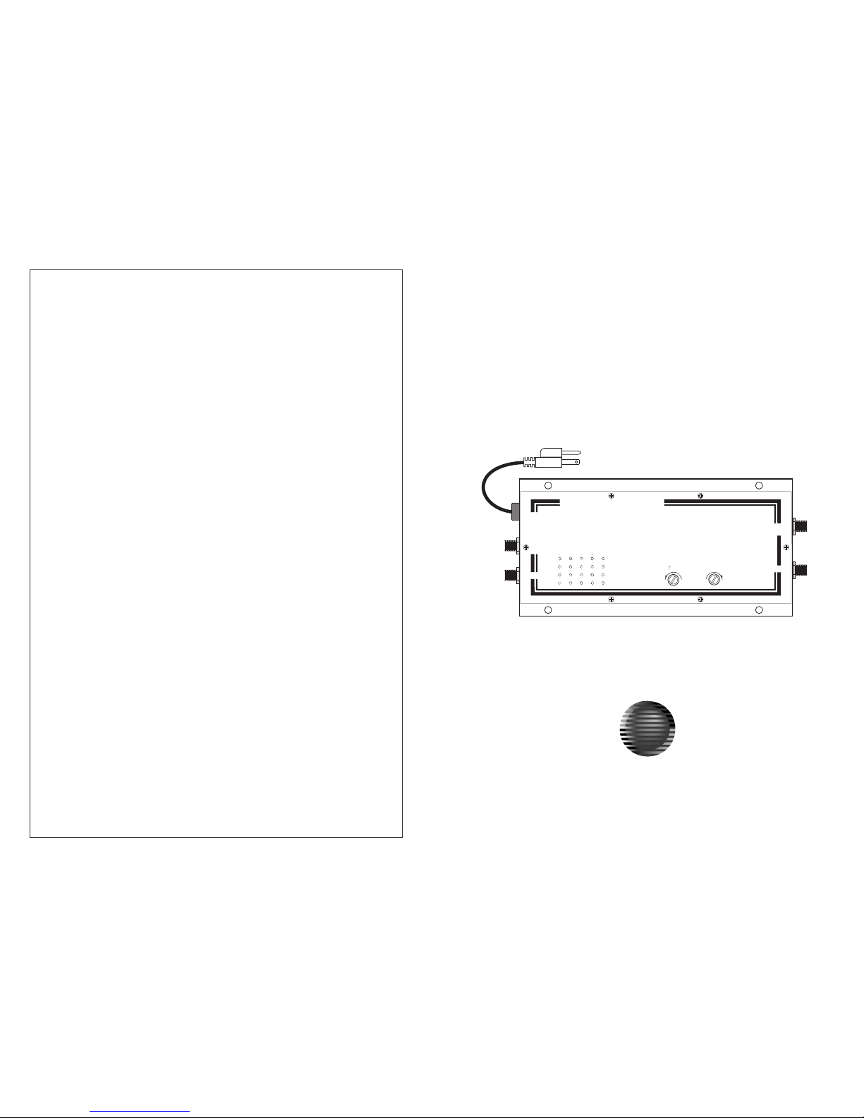
Bi-directional Broadband
RF amplifier
CVT-38BID
CVHANNEL ISION
TM
© 2003 Channel Vision Technolo
gy
234 Fischer Avenue Costa Mesa, CA 92626
(714) 424-6500 (800) 840-0288 (714) 424-6510 fax
www.channelvision.com email: sales @ channelvision.com
·
··
·
CHANNEL ISIONV
POWER IN
AC 110V
OUTPUT TEST
-20dB
OUTPUT
MODEL CVT-38BID
CATV DISTRIBUTION AMPLIFIER
REVERSE 5-42MHz
FORWARD 54-860MHz
38dB GAIN
TILT
MAX
GAIN
MAX
INPUT TEST
-20dB
INPUT
TM
Page 2
2
Basic system
The RF amplifier that covers all TV bands and provides a 542MHz reverse channel for CATV upstream information. The CVT-38BID includes a variable
input attenuator to reduce the possibility of over driving. The CVT-38BID also includes variable
tilt compensation to allow large systems to be properly balanced.
CVT-38BID is a high gain
The CVT-38BID is suitable for use with CATV or antenna systems.
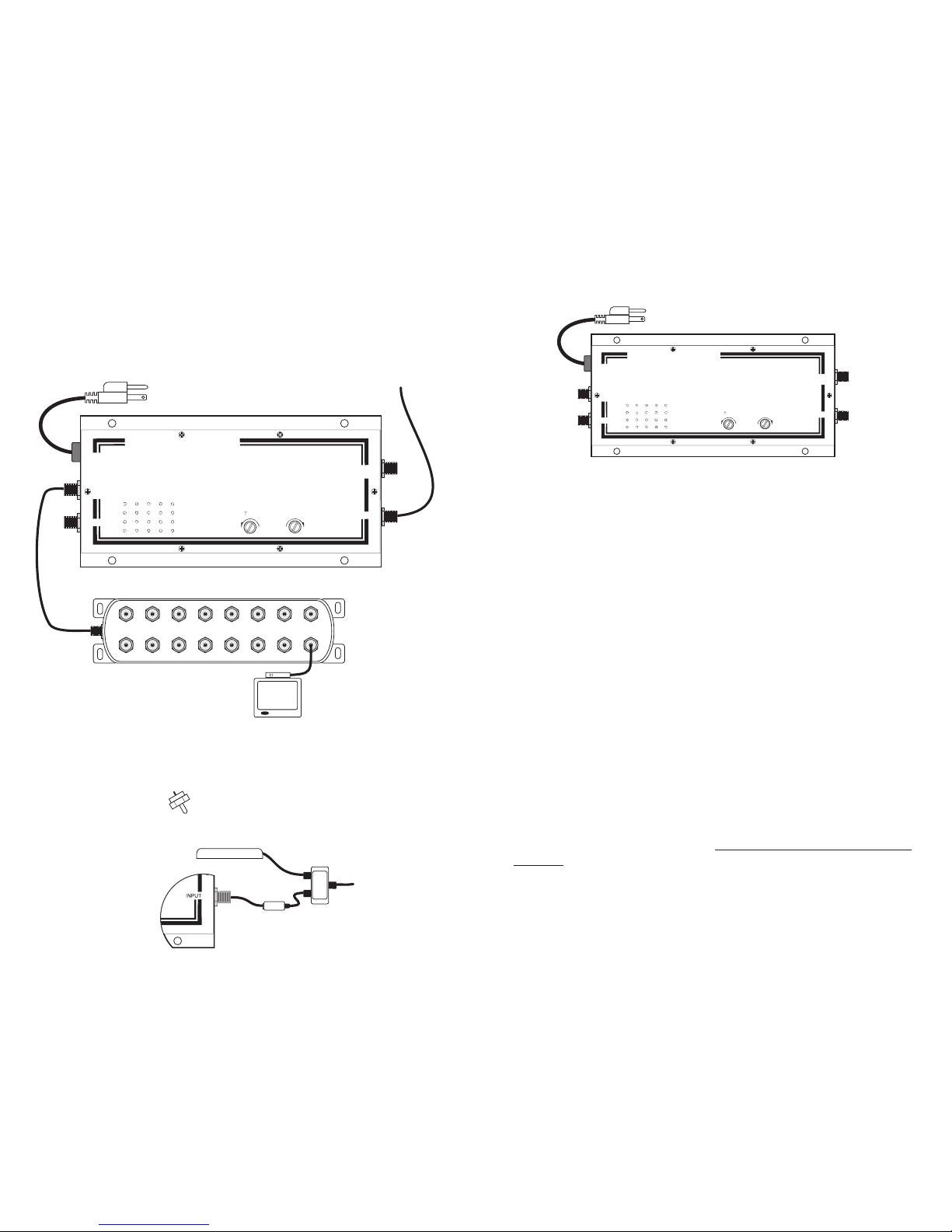
Input from
Cable system
HS-16
The
CVT-38BID is powerful enough to
feed a large number of TVs. Here we
show using an HS-16 16 way splitter
to distribute video in a large house.
Individual set-top boxes can send information to the cable company on
the 5-42MHz reverse channel.
Unused splitter ports should be terminated with a model 2101 75 ohm
terminator.
1of16TVs
with set-top boxes
Model 2101
Cable modem
Cable modems should
be fed from a splitter
ahead of the CVT-38BID.
From Cable
company
Using a Cable modem
Filter (usually supplied
by cable company)
HS-2
CHANNEL ISIONV
POWER IN
AC 110V
OUTPUT TEST
-20dB
OUTPUT
MODEL CVT-38BID
CATV DISTRIBUTION AMPLIFIER
REVERSE 5-42MHz
FORWARD 54-860MHz
38dB GAIN
TILT
MAX
GAIN
MAX
INPUT TEST
-20dB
INPUT
TM
3
Adj
usting gainandtilt controls
Gain control ... The gain control is a variable attenuator that will reduce
the level of the signal before the gain stage of the CVT-38BID. The number
one problem with video distribution systems is inter-modulation (IM)
distortion caused by over driven amplifiers. The symptom of IM is a
herringbone pattern on one or more channels.
1) Connect the CVT-38BID to the incoming cable signal and view a TV
connected to the output test jack.
2) Set the gain to MAX.
3) Examine all channels for herringbone patterns.
4) While viewing a herringbone pattern on one channel, decrease the gain
until the pattern goes away. (If the pattern does not change, the CVT38BID is not the cause of this problem.)
5) Examine all channels to be sure this gain setting is appropriate.
The ideal gain setting is one that eliminates IM distortion, but is not so low
as to introduce noise into the system.
. The goal of RF distribution systems is to distribute all
channels at equal amplitude. However, coaxial cable attenuates high
frequencies more than low. At the end of several hundred feet of coax, a
UHF channel can suffer over 10dB more loss than a VHF channel. The tilt
control introduces opposite losses into a system to compensate. The tilt
control is useful when you have long runs and multiple amplifiers. But
setting the tilt control correctly is not simple.
1) Using a field strength meter or spectrum analyzer, adjust the tilt control
so all signals are the same amplitude
.
2) If you do not have this instrumentation, leave the tilt control at the
minimum setting. Do not attempt to adjust tilt without the proper
equipment. You will probably create more problems than you will solve.
3) When feeding TVs rather than another amp, the tuned front-end of a TV
usually makes tilt unnecessary and the tilt control should be left at
minimum.
Tilt control ..
at the point where the coax feeds the
next amp
CHANNEL ISIONV
POWER IN
AC 110V
OUTPUT TEST
-20dB
OUTPUT
MODEL CVT-38BID
CATV DISTRIBUTION AMPLIFIER
REVERSE 5-42MHz
FORWARD 54-860MHz
38dB GAIN
TILT
MAX
GAIN
MAX
INPUTTEST
-20dB
INPUT
TM
 Loading...