

Page 1
DC1 2V
DC1 2V
INP UT
INP UT
RF IN PUTRF IN PUT
CHA NNEL V I SION
TM
CVT-15WB
CATV F orw ard Pat h (54-8 60MHz ):+15 dB
CATV R etu rn Path ( 5-42M Hz): Pa ssive
Wid eBand C ATV Path ( 975 -1525 MHz): Passi ve
OUT +POWE ROUT +POWE R
CVT-15WB
15dB Amplifier for Standard & Wide-Band
CATV Systems
1
0
Page 2
The CVT-15WB is a 15dB Amplifier for standard and advanced digital
CATV systems. The wide bandwidth design allows 2-way communications
in the RF spectrum from 975-1525MHz which is required by some newer
digital cable boxes.
Features:
!
15dB Amplifier
!
Passive return path from 5-42MHz
!
Compatible with Advanced Wide-Bandwidth Digital CATV systems
!
Built-in 6KV surge protection for superior durability
!
Phantom powered using model CVT-PI
!
Easy installation
!
Dimensions: 4.70” x 4.35” x 1.06”
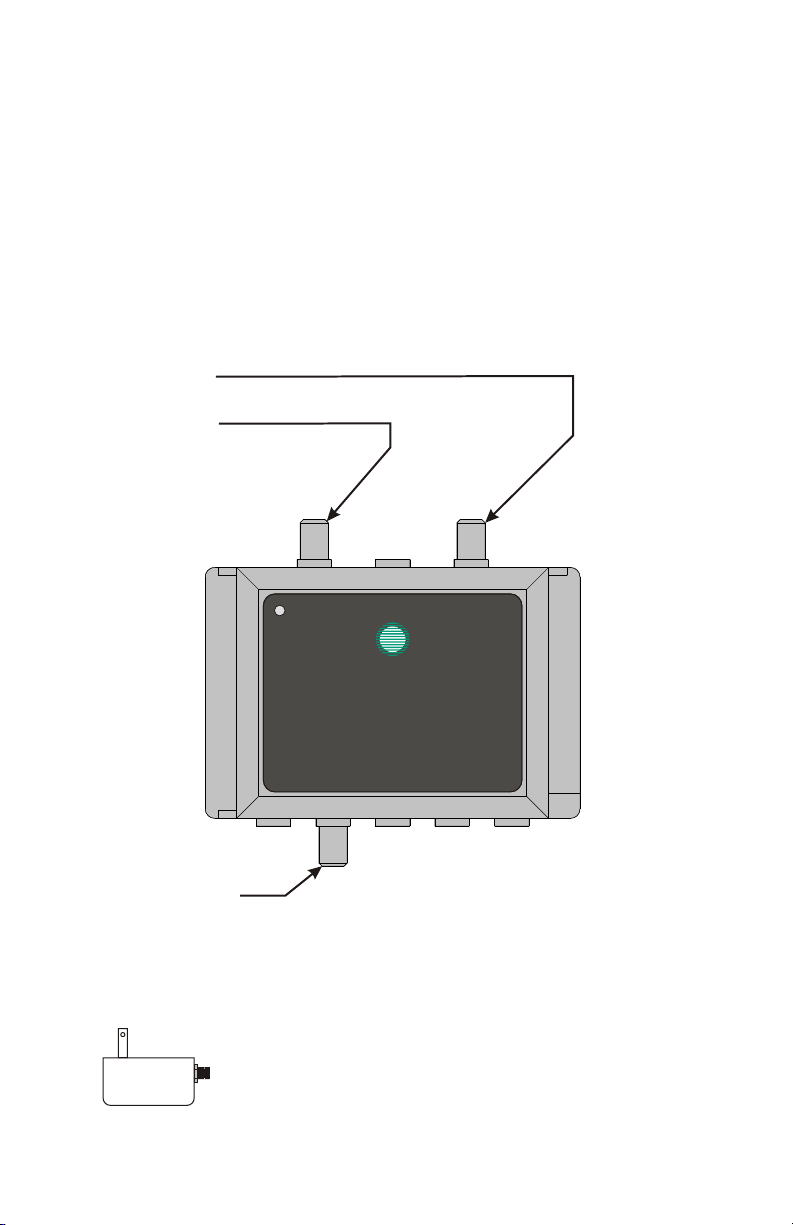
CABLE IN
Connect the antenna or cable service feed here
POWER IN
Connect power supply here
TV OUTPUTS
Connect TVs here
Accessories Included:
Power Supply
12VDC, 500mA
2
DC1 2V
DC1 2V
INP UT
INP UT
RF IN PUTRF IN PUT
CH ANN EL VI SIO N
CVT-1 5W B
CATV Fo rward P ath (54 -860M Hz):+ 15dB
CATV Re turn Pa th (5-4 2MHz) : Passi ve
Wid eBand C ATV Path (9 75-15 25MHz ):Pas sive
OUT +POWE ROUT +POWE R
TM
Page 3
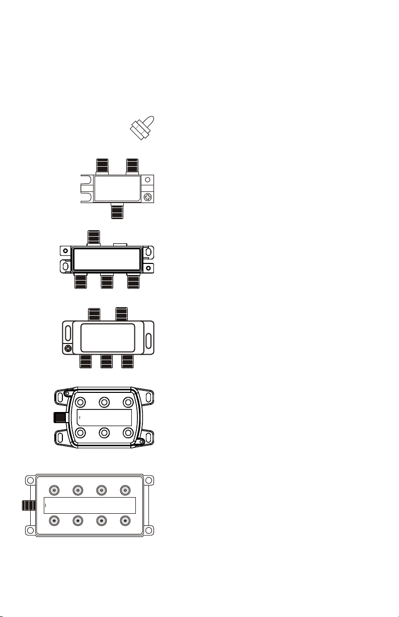
Accessories & Complementary Products (sold separately)
RF distribution systems require splitters and other accessories to deliver
the amplified signals to the TV.
2120 ... 75ohm RF terminator. Use to
terminate unused outputs of splitters.
OUT/inOUT/in
CHA NN EL V ISI ON
Part No. HS-2
2-WAY SPLITTER/COMBINER
5MHz-1GHz All Port DC passing
/out
IN
/out
IN
CH ANN EL V ISI ON
3-WAY SPLITTER/COMBINER
5MHz-1GHz All Ports DC passing
OUT/in OUT/in OUT/in
CHA NN EL V ISI ON
4-WAY SPLITTER/COMBINER
5MHz-1GHz All Port DC passing
Part No. HS-3
Part No. HS-4
/outOUT/in OUT/in
IN
TM
OUT/inOUT/in
TM
TM
HS-2 ... 2-way RF splitter for cable TV and
antenna signals.
HS-3 ... 3-way RF splitter for cable TV and
antenna signals.
HS-4 ... 4-way RF splitter for cable TV and
antenna signals.
OUT OUT OUT
CHA NNE L V ISIO N
IN
OUT OUT OUT
OUT OUTOUT OUT
IN
CH ANN EL V ISI ON
OUT OUTOUT OUT
TM
Part No. HS-6
6-WAY SPLITTER 5MHz-1GHz
All ports DC passing
Part No. HS-8
TM
8-WAY SPLITTER 5MHz-1GHz
All ports DC passing
HS-6 ... 6-way RF splitter for cable TV and
antenna signals.
HS-8 ... 8-way RF splitter for cable TV and
antenna signals.
3
Page 4

Basic RF System Design
Knowing how much amplification is needed for a system is essential to
designing a successful RF distribution system. This section explains how to
calculate the losses in your system. You should provide enough amplification
to overcome all of the insertion losses of all the system components. If the
signal splits into two branches, each branch must be calculated separately.
System Component
100ft. of RG6
HS-2 (2-way Splitter)
HS-3 (3-way Splitter)
HS-4 (4-way Splitter)
HS-6 (6-way Splitter)
HS-8 (8-way Splitter)
HS-16 (16-way Splitter)
CVT-15WB
Gain:
+15dB
Typical Insertion Loss
Antenna
or CATV
DC12V
DC12V
INPUT
INPUT
CH ANN EL V ISI ON
CATV For ward Pa th (54- 860MH z):+1 5dB
CATV Ret urn Pat h (5-42 MHz): P assiv e
WideB and CATV P ath (97 5-152 5MHz) :Pass ive
OUT+P OWEROUT+P OWER
RF INPU TRF INPU T
CVT- 15WB
+25dBmV
~5.0dB
3.5dB
5.5dB
7.5dB
9.0dB
11.0dB
15.5dB
+10dBmV
TM
Example: Assume a CATV input
signal of 10dBmV. Next, calculate
all the gains and losses of the
components.
Primary Branch Calculation:
CATV Input: 10dBmV
CVT-15WB: +15dB
HS-2: -3.5dB
Main total: +21.5dBmV
4-Way Branch:
Main: +21.5dBmV
HS-4: -7.5dB
+14.5dB
6-Way Branch:
Main: +21.5dBmV
HS-6: -9.0dB
+11.5dB
Insertion Loss:
IN
TM
OUT/inOUT/in
/out
Part No. HS-2
-3.5dB
5MHz-1GHz All Port DC passing
2-WAY SPLITTER/COMBINER
CH ANN EL V ISI ON
+21.5dBmV +21.5dBmV
Insertion
Loss:
-7.5dB
IN
/outOUT/in OUT/in
5MHz-1GHz All Port DC passing
4-WAY SPLITTER/COMBINER
Part No. HS-4
CH ANN EL V ISI ON
TM
OUT/inOUT/in
4
+14.5dBmV
Insertion Loss: -9dB
OUT OUT OUT
CH ANN EL V ISI ON
IN
OUT OUT OUT
TM
Part No. HS-6
6-WAY SPLITTER 5MHz-1GHz
All ports DC passing
+11.5dBmV
Page 5

Basic Amplified Splitter Application
Connect the CVT-15WB as shown and locate it at the main distribution point in
the house. The CVT-15WB will supply the amplified TV signal to the splitter
which may be conned to several TV locations.
Power
Supply
Input from
Antenna or CATV
CVT-15WB
TV set
DC12 V
DC12 V
INPU T
INPU T
RF INP UTRF INP UT
CH AN NE L VI SI ON
CVT-15 WB
CATV Fo rward P ath (54 -860M Hz):+ 15dB
CATV Re turn Pa th (5-4 2MHz) : Passi ve
Wide Band CAT V Path (9 75-15 25MHz ):Pas sive
OUT+ POWEROUT+ POWER
IN
/outOUT/in OUT/in
5MHz-1GHz All Port DC passing
4-WAY SPLITTER/COMBINER
Part No. HS-4
TM
OUT/inOUT/in
CH ANN EL V ISI ON
TM
TV set
TV set
TV set
5
Page 6

Basic RF System Design
Knowing how much amplification is needed for a system is essential to
designing a successful RF distribution system. This section explains how to
calculate the losses in your system. You should provide enough amplification
to overcome all of the insertion losses of all the system components. If the
signal splits into two branches, each branch must be calculated separately.
System Component
100ft. of RG6
HS-2 (2-way Splitter)
HS-3 (3-way Splitter)
HS-4 (4-way Splitter)
HS-6 (6-way Splitter)
HS-8 (8-way Splitter)
HS-16 (16-way Splitter)
CVT-15WB
Typical Insertion Loss
Antenna
or CATV
DC12V
DC12V
INPUT
INPUT
CH ANN EL V ISI ON
CATV For ward Pa th (54- 860MH z):+1 5dB
CATV Ret urn Pat h (5-42 MHz): P assiv e
WideB and CATV P ath (97 5-152 5MHz) :Pass ive
OUT+P OWEROUT+P OWER
RF INPU TRF INPU T
CVT- 15WB
+25dBmV
~5.0dB
3.5dB
5.5dB
7.5dB
9.0dB
11.0dB
15.5dB
+10dBmV
TM
Example: Assume a CATV input
signal of 10dBmV. Next, calculate
all the gains and losses of the
components.
Primary Branch Calculation:
CATV Input: 10dBmV
CVT-15WB: +15dB
HS-2: -3.5dB
Main total: +21.5dBmV
4-Way Branch:
Main: +21.5dBmV
HS-4: -7.5dB
+14.5dB
6-Way Branch:
Main: +21.5dBmV
HS-6: -9.0dB
+11.5dB
IN
/out
5MHz-1GHz All Port DC passing
2-WAY SPLITTER/COMBINER
Part No. HS-2
OUT/inOUT/in
CH ANN EL V ISI ON
TM
+21.5dBmV +21.5dBmV
IN
/outOUT/in OUT/in
5MHz-1GHz All Port DC passing
4-WAY SPLITTER/COMBINER
Part No. HS-4
CH ANN EL V ISI ON
TM
OUT/inOUT/in
6
+14.5dBmV
OUT OUT OUT
CH ANN EL V ISI ON
IN
OUT OUT OUT
TM
Part No. HS-6
6-WAY SPLITTER 5MHz-1GHz
All ports DC passing
+11.5dBmV
Page 7

Specifications: (typical @25º C)
ITEM MIN. MAX.TYP.
Gain
(Passive) 975-1525MHz
Flatness
Return Loss (I/O)
Noise Figure@70 degrees F
Group Delay (54 to 66MHz)
Group Delay (66 to 88MHz)
Group Delay (88 to 1000MHz)
Composite Second Order Distortions
Composite Triple Beat Distortions
Cross Modulation Distortions
Second Hum Modulation
Rated Output Level @160 channels, 6MHz each
Power Consumption
CATV FORWARD PATH
54-60MHz
60-860MHz
+14.0dB
+14.0dB
-4.0dB
54-1525MHz
+15.0dB
+15.5dB
-2.5dB
+1.0dB
>15dB
3.0dB
60ns
22ns
12ns
60dBC
60dBC
60dBC
70dBC
+23.0dBmV
150mA
+16.0dB
+16.0dB
-1.5dB
Frequency Range
Flatness
Return Loss (I/O)
RFI Shielding
Nominal Impedance “F” Female
Supply Voltage (DC)
CATV RETURN PATH
5-42MHz
975-1000MHz
1000-1525MHz
GENERAL SPEC
5-42 + 975-1525MHz
-3.0dB
-5.0dB
-3.5dB
Specifications subject to change without notice.
-2.0dB
-4.0dB
-2.5dB
+1.0dB
>15dB
>110dB
75 ohm
12-15VDC
-1.0dB
-3.0dB
-1.5dB
7
Page 8

1
Channel Vision Technology will repair or replace any defect in
material or workmanship which occurs during normal use of this
product with new or rebuilt parts, free of charge in the USA, for one
year from the date of original purchase. This is a no hassle warranty
with no mail in warranty card needed. This warranty does not cover
damages in shipment, failures caused by other products not supplied
by Channel Vision Technology, or failures due to accident, misuse,
abuse, or alteration of the equipment. This warranty is extended only
to the original purchaser, and a purchase receipt, invoice, or other
proof of original purchase date will be required before warranty
repairs are provided.
Mail in service can be obtained during the warranty period by calling
(800) 840-0288 toll free. A Return Authorization number must be
obtained in advance and can be marked on the outside of the shipping
carton.
This warranty gives you specific legal rights and you may have other
rights (which vary from state to state). If a problem with this product
develops during or after the warranty period, please contact Channel
Vision Technology, your dealer or any factory-authorized service
center.
Channel Vision products are not intended for use in medical,
lifesaving, life sustaining or critical environment applications.
Channel Vision customers using or selling Channel Vision products
for use in such applications do so at their own risk and agree to fully
indemnify Channel Vision for any damages resulting from such
improper use or sale.
w ww .c ha nn elv isi on .c om
234 Fischer Avenue, Costa Mesa, California 92626 USA
(714)424-6500 (800)840-0288 (714)424-6510 fax
email: techsupport@channelvision.com
500-253 rev A
 Loading...