

Page 1
C
C
H
H
A N N E L
A N N E L
T
T
M
PRO
V
V
V
I uT
np
M
I S
I S
I O
I O
N
N
t
I O t
R u
Pat.
g
Pe
ndin
o
eP w r
CA
P-0321
Digital Cable Combiner
M do
e
l
P
-
0
32
1
uMOD Inp t
O
u
t ut
p
PRO
PRO
7
Page 2
The P-0321 allows you to integrate modulated signals into a digital cable
system without using an RF filter. This allows several modulated channels
to be integrated with a full digital cable feed without requiring any digital
programming to be filtered out.
Features:
!
Enables modulation into a digital cable system without using a filter
!
Built-in IR repeating system
!
Easy installation
!
Remote control and IR coax adaptor with IR receiver included
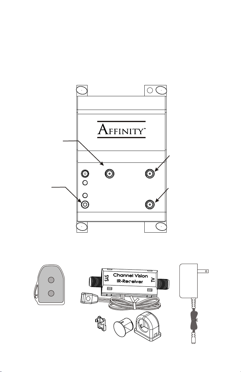
CATV Input
Connect the
digital cable
service feed
here
Pat. Pending
Power
C HA NN EL
C HA NN EL
TM
TM
V IS IO N
V IS IO N
PRO
CATV Input
Model
P-0321
MOD Input
MOD Input
Connect modulator
here
IR Out
Output for IR
emitters. This
can be used
to control
other devices
Included Accessories:
Remote Control
Channel
TM
Vision
Modulator
CATV
A0511
2
IR Out
IR Coax Adaptor
with IR Receiver
IR Receiver
Mounting Accessories
Output
Output
Connect TVs here
Power Supply
Page 3
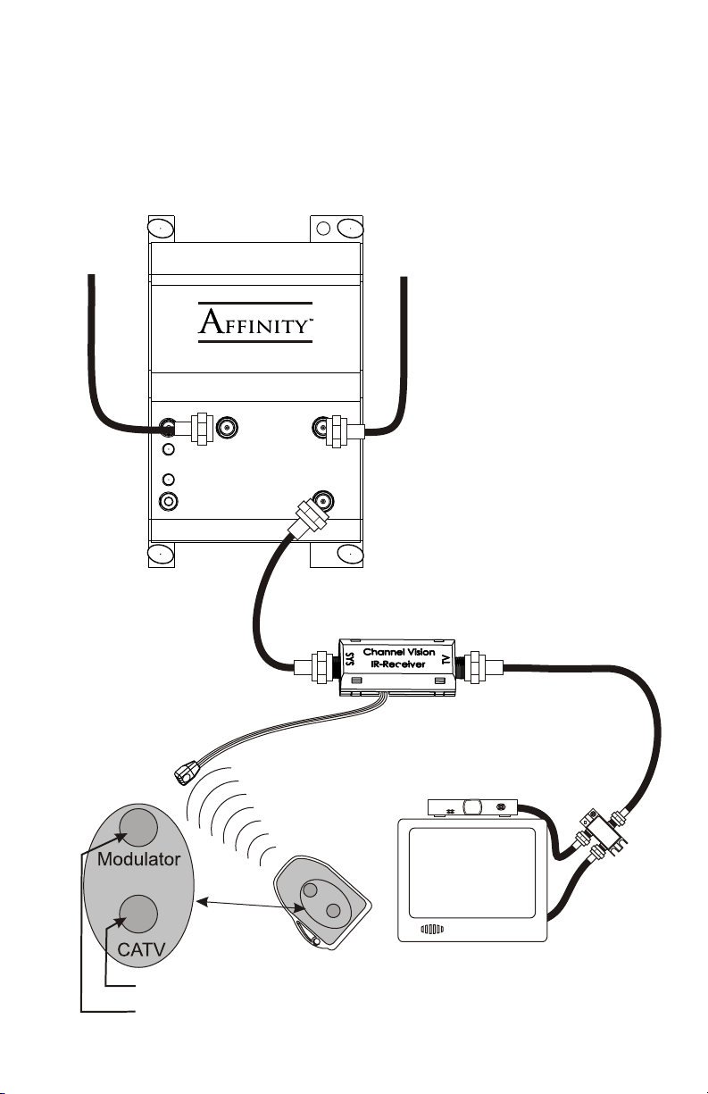
Basic Application
Connect the P-0321 as shown and locate it at the main distribution point in the
house. The output of the P-0321 will send both CATV and the modulator’s
output to the TV location over a single coax cable. Switching between the
CATV and modulator signals is simple: just point the remote at an IR receiver
connected to the coax-based IR system and the IR signal will travel back to the
P-0321 and change it to the desired input.
Input from
CATV
Pat. Pending
Power
IR Out
P-0321
CH AN NEL
CH AN NEL
TM
TM
VI SI ON
VI SI ON
PRO
CATV Input
Input from
Modulator
Model
P-0321
MOD Input
Output
IR Coax Adaptor
with IR receiver
Note: See TV connection
details on the following page
Digital CATV Box
TM
on
i
s
i
r
Channel
V
to
a
l
odu
M
VC
AT
1
A0 15
TV set
MOD - Selects the modulator input on the P-0321
CATV - Selects the CATV input on the P-0321
C
HA
2
-W
NNE
IN
AY
/
5
ot
M
Pa
u
OU
S
H
L VIS
z
rt N
P
-1G
L
T
ITTE
/i
H
o
n
z
.
All P
H
ION
R
S
-2
/C
o
rt
TM
O
D
M
C pa
B
IN
ss
E
in
R
g
OUT
/i
n
3
Page 4

Connecting the Digital Cable Box to the TV
For best results, use a 2-way RF splitter to feed the RF inputs of the CATV box
and the TV set. Then use RCA cables to connect the audio/video outputs from
the CATV box to the audio/video inputs of the TV.
CATV Box
Connections
From
IR coax adaptor
with IR receiver
Digital CATV Box
Input
Video
RF
Outputs
Left
Right
HS-2
2-way
splitter
OUT/in
2-WAY SPLITTER/COMBINER
CHA NNE L V ISIO N
5MHz-1GHz All Port DC passing
Part No. HS-2
IN
/out
OUT/in
TM
TV set
RCA
cables
Video
Aux. Input
RF
Input
Left
Right
TV Connections
How to Use the System
To watch the CATV box, select “CATV” on the remote control and then select
the A/V input on the TV.
To watch the modulated channels, select “Modulator” on the remote
control, then select the RF input on the TV and tune to the modulated channel
with the TV remote control.
4
Page 5

Using the P-0321 with the E-Series IR Modulators
When connected as shown below, IR signals will pass through the P-0321 and
travel back to the IR emitter outputs on the E4200IR. This allows you to utilize
the built-in IR repeating system to control source components such as satellite
receivers and DVD players.
Input from
CATV
Pat. Pending
Power
IR Out
IR Emitter
P-0321
CH AN NEL
CH AN NEL
TM
TM
VI SIO N
VI SIO N
PRO
CATV Input
Sat Receiver
BB
OUTPUT
OUTPUT
AA
IR
IR
RF OUTRF OUT
L RL R
AUDIOAUDIO
VIDEOVIDEO
L RL R
AUDIOAUDIO
Camera
Model
P-0321
MOD Input
Output
S
g alIR i n
s
IR Coax Adaptor with IR receiver
DD
CC
VIDEOVIDEO
Camera
11223344
OUTPUT
OUTPUT
IR
IR
VCR
CABLECABLE
ANTENNAANTENNA
ANTENNA + CABLEANTENNA + CABLE
33
44
11
22
E4200IR
DC 15V INDC 15V IN
Digital CATV Box
CH
ANN
2
-W
IN
A
/ou
5
Y
M
Part No.
EL
O
S
H
t
z
UT
P
1G
VISION
L
ITT
/in
H
zA ot C
H
E
ll
R
S-2
P
/C
r D
TM
OMB
p
a
IN
s
s
E
in
R
g
OU
T
/i
n
M
T
n le
n
sion
r
Cha
Vi
ato
u
d l
o
M
V
T
A
C
51
0 1
A
TV set
5
Page 6

Systems with Multiple Digital CATV Boxes
To create systems with multiple locations, simply split the output of the
modulator and the CATV feed, then connect the outputs of the splitters to each
P-0321. For larger systems, use splitters with more outputs.
Input
From CATV
CHA NNE L
CHA NNE L
TM
TM
Pat. Pending
VIS ION
VIS ION
PRO
CATV Input
Power
IR Out
P-0321
Model
MOD Input
Sat Receiver
BB
OUTPUT
OUTPUT
AA
IR
IR
RF OUTRF OUT
L RL R
AUDIOAUDIO
Camera
IN
IN
/out
5MHz-1GHz All Port DC passing
2-WAY SPLITTER/COMBINER
Part No. HS-2
CHANNE L VI SI ON
TM
OUT/inOUT/in
/out
5MHz-1GHz All Port DC passing
2-WAY SPLITTER/COMBINER
Part No. HS-2
CHANNE L VI SI ON
TM
OUT/inOUT/in
L RL R
VIDEOVIDEO
AUDIOAUDIO
VIDEOVIDEO
Camera
This splitter must be DC
VCR
CABLECABLE
OUTPUT
OUTPUT
IR
IR
ANTENNAANTENNA
ANTENNA + CABLEANTENNA + CABLE
11223344
33
44
11
22
DC 15V INDC 15V IN
DD
CC
and IR passing.
CHA NNE L
CHA NNE L
Model
TM
TM
Pat. Pending
Power
IR Out
Output
VIS ION
VIS ION
PRO
CATV Input
P-0321
MOD Input
Output
Room 1
C
H
ANN
2-WA
IN
/o
5MHz-1
Y
P
EL
u
OU
SP
art No. H
t
VISI
LI
T
GHz Al
/in
TT
ER
l P
ON
S-2
/C
ort DC pa
MT
O
M
B
INE
ss
ing
R
O
U
T
l
e
TM
n
n
a
io
is n
r
Ch
o
V
at
ul
d
Mo
V
T
A
C
511
6
A0
/in
Room 2
el
M
T
n
n
a
h
sion
i
r
C
o
V
t
l
ua
d
o
M
ATV
C
1
1
5
A0
C
H
AN
2
-WA
IN
N
/o
5Hz- zAl ort DC pssng
Y
M
Par
EL
u
O
SITE / OMBIER
t
U
P
V
t N
1GH
LT
T
/in
o.
ISI
H
lP
ON
RC N
S-2
TM
ai
O
UT
/in
Page 7

Troubleshooting
If your IR system is not working, check to see if the P-0321 is feeding
approximately 12 Volts DC onto the coax between the shield and center
pin. (Any voltage between 8-12VDC is OK). If there is no voltage
between the center pin and shield, check the connectors on each end of
the coax.
CH AN NEL
Pat. Pending
Power
CH AN NEL
VI SIO N
VI SIO N
PRO
CATV Input
Model
TM
TM
P-0321
MOD Input
IR Out
Output
VDC
If you are using an RF splitter between the modulator and the P-0321 or
between the P-0321 and the IR coax adaptor (IR-4101), check to make
sure you have approximately 8-12 Volts DC on the coax going into the
IR-4101. If there is no voltage at that point, check the following items:
1. Make sure you are using a DC passing splitter. Traditional splitters will
short out DC voltage traveling on the coax and prevent your IR system
from working.
2. Make sure that there are DC blocks (model 3109) on any output from
the RF splitter that will not be connected to an IR-4101. If outputs
from the splitter are connected directly to TV sets without going
through a IR-4101 or DC block, the system voltage will be shorted out
by the input of the TV set.
3. Double check the fittings at the end of your coax cables. If a little bit of
shielding is touching the center pin, the voltage will be shorted out and
the system will not work.
4. Don’t worry. The IR engine has a current limiting circuit. If the engine
is shorted (due to a bad connection or a non-DC passing splitter)
nothing will be harmed.
7
Page 8

Channel Vision Technology will repair or replace any defect in material or
workmanship which occurs during normal use of this product with new or rebuilt
parts, free of charge in the USA, for two years from the date of original purchase.
This is a no hassle warranty with no mail in warranty card needed. This warranty
does not cover damages in shipment, failures caused by other products not
supplied by Channel Vision Technology, or failures due to accident, misuse, abuse,
or alteration of the equipment. This warranty is extended only to the original
purchaser, and a purchase receipt, invoice, or other proof of original purchase date
will be required before warranty repairs are provided.
Mail in service can be obtained during the warranty period by calling (800) 840-
0288 toll free. A Return Authorization number must be obtained in advance and
can be marked on the outside of the shipping carton.
This warranty gives you specific legal rights and you may have other rights (which
vary from state to state). If a problem with this product develops during or after the
warranty period, please contact Channel Vision Technology, your dealer or any
factory-authorized service center.
Specifications: (typical at 25 degrees C)
Forward Gain
CATV in to out 54-1000MHz +4dB
MOD in to out 54-1000MHz -13dB
Reverse Channel
Out to CATV in
5-42MHz <-7dB
Isolation:
CATV in to TV output 54-1000MHz >50dB (60dB typical)
MOD in to TV output 54-1000MHz >50dB (60dB typical)
IR Over Coax
Compatible with Channel Vision IR-4100 and IR-4101 only.
Power Supply 15VDC, 450mA unregulated
Specifications subject to change without notice
w ww .c ha nn elv is i on .c om
234 Fischer Avenue, Costa Mesa, California 92626 USA
(714)424-6500 (800)840-0288 (714)424-6510 fax
email: techsupport@channelvision.com
500-161 rev C1
 Loading...