

Page 1
AB-313
® ®
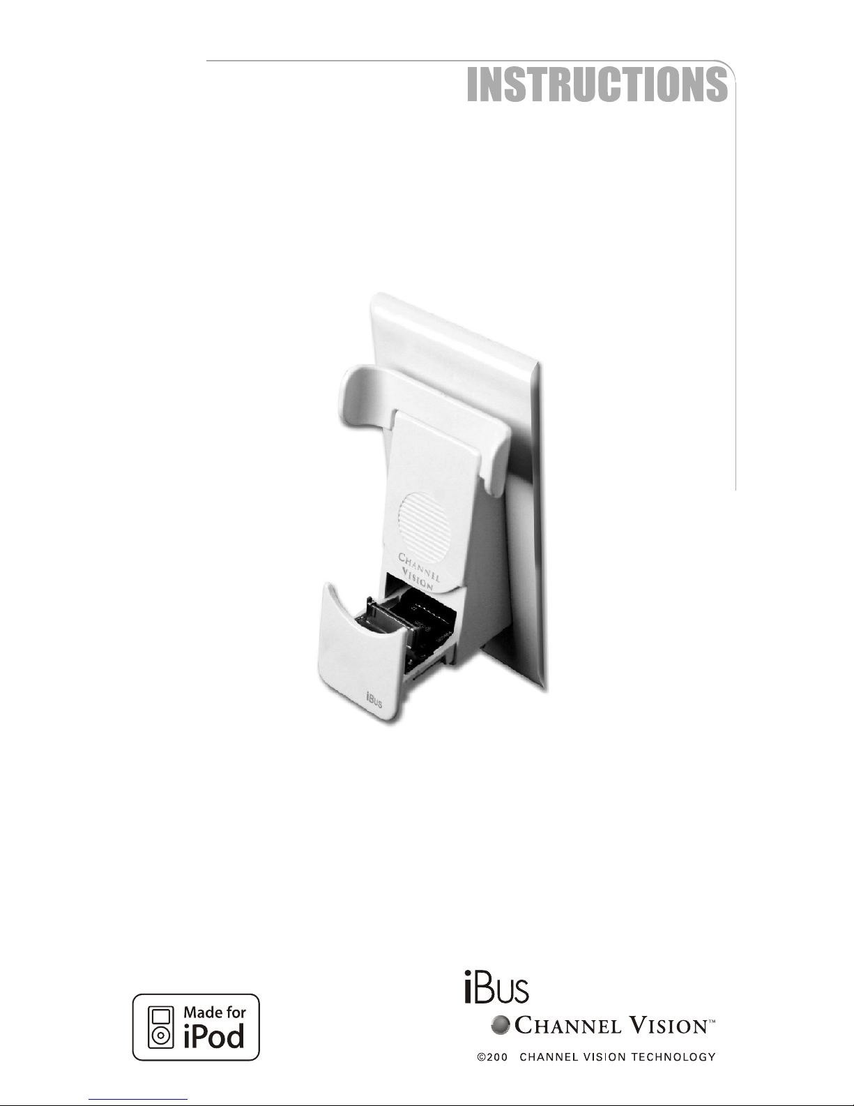
iBus Wall-Dock for A-BUS Audio Systems
By
®
7
Page 2
2
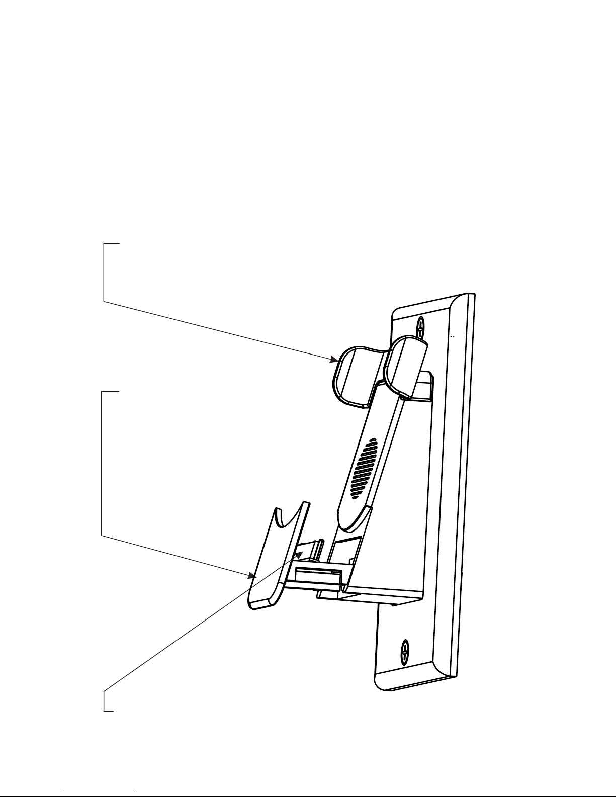
Slide-out Cradle
Provides support for the iPod
and holds the dock connector.
The support ledge slides into
the AB-313 when not in use.
Support Clip
Holds the top of the iPod securely.
3 support clips are supplied:
1 for iPod mini, 1 for iPod nano, and 1 for other iPod models
AB-114 AB-124
Amplified Keypad:
Speakers:
In-ceiling, In-wall and free-standing 8 ohm speakers are acceptable.
Dock Connector
Delivers power to the iPod for charging and provides audio to the
Channel Vision’s A-BUS whole-house audio system.
Features:
!
Compatible with all A-BUS audio systems
!
Charges the iPod
!
Senses audio to automatically override the main audio source
!
Supports IR control: compatible with A0501, A0502 or Apple Remote
!
Uses CAT5 cabling
Made For iPods with dock connector:
!
iPod video
!
IPod nano
!
iPod photo
!
IPod mini
!
4th Generation iPod with omni (dock) connector
!
3rd Generation iPod with omni (dock) connector*
The AB-313 is not a standalone device. It must be installed as part of an
audio system which requires the following components:
®
The AB-313 is a local input module for A-BUS audio systems that was
® ®
specially designed for the Apple iPod and iPod mini. The attractive wall
mount remains unobtrusive while not in use, yet its support ledge with
integrated dock connector slides out easily, ready to dock your iPod at all
times. (See Made For section on page 3 for a list of compatible iPods.)
Hub with Power Supply:
This product is compatible with all Channel Vision A-BUS products as
well as all 3rd party products that carry the A-BUS Logo.
TM
CHANN EL V ISI ON
byby
ININ
OUTOUT
11
22
*3rd Generation iPods are not capable of being charged by this product, but audio playback will function normally.
Page 3
3
OR
AB-114 AB-124
Or
Amplified Keypad:
Speakers:
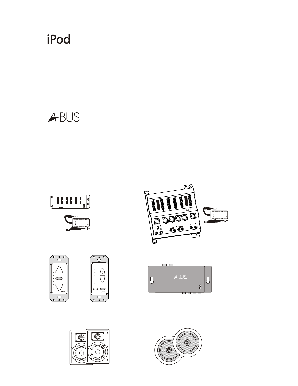
In-ceiling, In-wall and free-standing 8 ohm speakers are acceptable.
Made For iPods with dock connector:
!
iPod video
!
IPod nano
!
iPod photo
!
IPod mini
!
4th Generation iPod with omni (dock) connector
!
3rd Generation iPod with omni (dock) connector*
The AB-313 is not a standalone device. It must be installed as part of an
audio system which requires the following components:
Compatibility
Other Required Components
Hub with Power Supply:
AB-404
P-1014
(power supply included)
AB-T2454
AB-202
Single Source Input Module:
This product is compatible with all Channel Vision A-BUS products as
well as all 3rd party products that carry the A-BUS Logo.
®
TM
CHANN EL V ISI ON
byby
ININ
OUTOUT
11
22
33
44
BRN
WHT/BRM
BLU
WHT/BLU
GRN
WHT/GRN
ORG
WHT/ORG
1 - i u o Mo u4 A BUS Distr b ti n d le
odel
M
P-1 14
0
+2 VD4 C
Pow re
+1 V2 DC
tusSta
steSy m
S stey m
Input
calLo
uInp t
one 1Z
2Zone Zone 3
one 4
Z
x nsionE pa
O p tut u
Local
Priority Signal
L R
mitters
E
PRO
N
NECHA L
TM
S
VI ION
IR
x
TM
By C HAN NEL VIS IO N
AUDIO
L
R
STATUS
12VDC
AB-202
A-BUS OUTPUT
STATUS
IR
IR EMITTERS
Source
CHA NN EL V ISI ON
Pwr
*3rd Generation iPods are not capable of being charged by this product, but audio playback will function normally.
Page 4
1 A- r Modul
4 BUS Dist ibution e
Mod l e
1 14P- 0
V+24 DC
Power
12V+ DC
S statu
Sys em
t
Sys emt
Input
L aloc
I unp t
Zone 1
e Zon 2
Z e 3on
Zone 4
E s
xpan ion
p
Out ut
cLo al
Priority
Signal
L R
Em ttersi
P OR
HA NE L
C N
MT
S O NVI I
IR
x
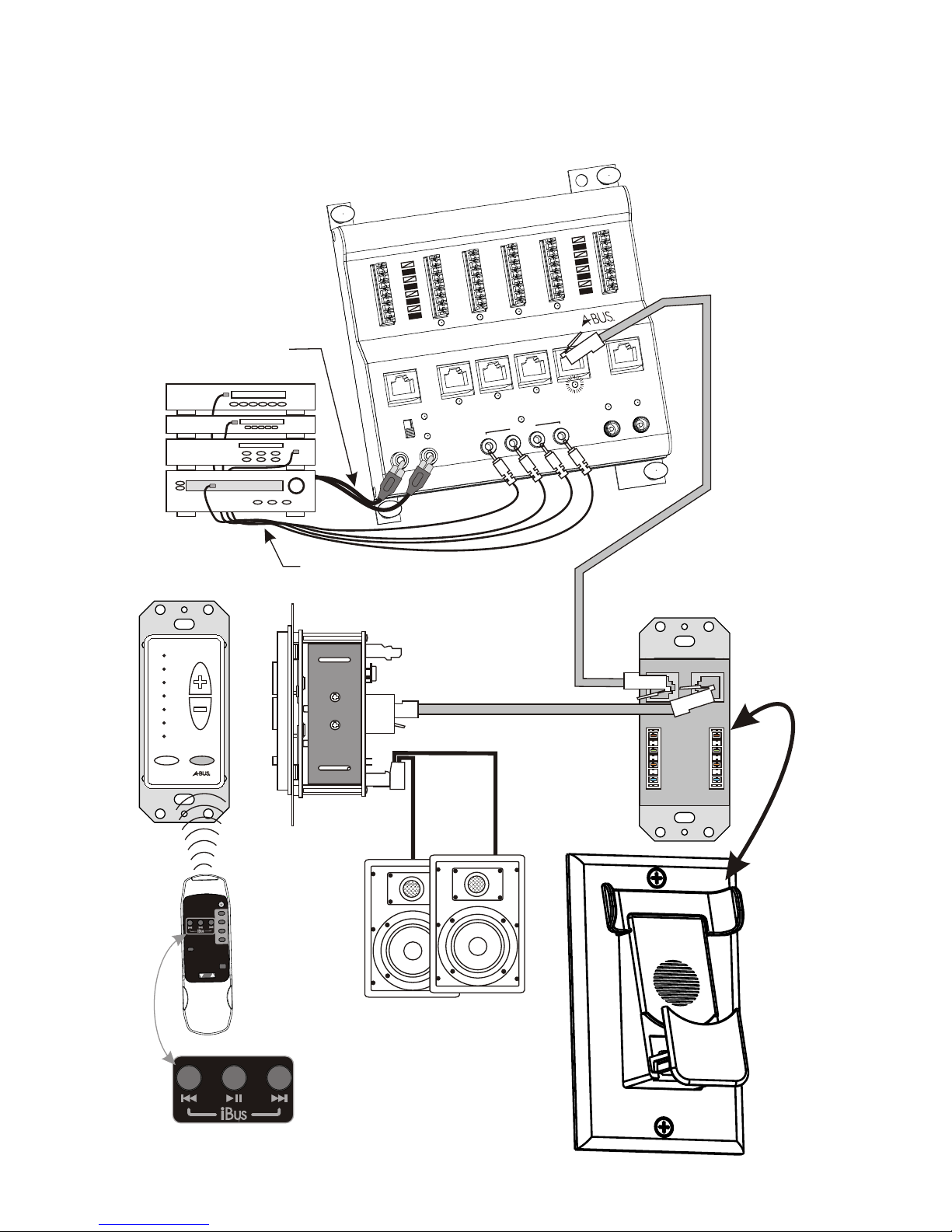
System Wiring Diagram
Using the AB-313 as a local source input module
Using the AB-313 as a main source input module
4
AB-124
P-1014
A0501
or
A0502
AB-313
(Rear)
AB-313
(Front)
Speakers
The shuttle control buttons
on the A0501 & A0502
remotes can be used
to control the iPod.
OUT
TOU
IN
IN
OUT
IN
NI
Tape Monitor or
Room 2 output
Tape Monitor or
Room 2 output
(Optional) IR emitters
Sat radio
Sat radio
DVD player
DVD player
CD player
CD player
Receiver
Receiver
Source
CH ANN EL V ISI ON
Pwr
TM
CH N NEL I I NA V S O
S
O
U
R
C
E
Z N
O E
ERPOW
MUTE
VOL
1
2
3
4
MO ELD
A0501
P
WER
O
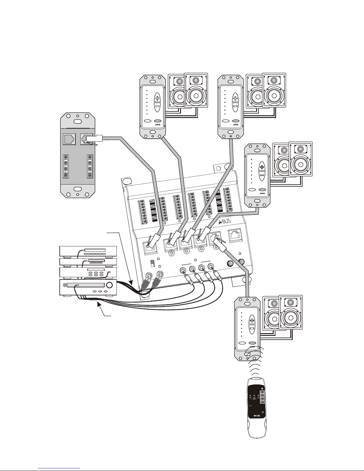
In this configuration, an iPod docked in the
AB-313 will override the other audio source
whenever the iPod is playing (note the
position of the priority switch on the P-1014).
The iPod can be controlled by pointing an
A0501 or A0502 remote control at any of the
amplified keypads.
Page 5
1 - odul 4 A BUS Distribution M e
Model
1 4P- 01
+24V CD
Power
V+12 DC
S atus
t
Sys emt
ys emS t
npI ut
L aoc l
I unp t
Zo e 1
n
Zone 2
e Zon 3
Zo e 4n
E p nsionx a
Output
cLo al
P o tyri ri
Si nal
g
L R
m ttersE i
PRO
EL CH AN N
TM
O
VI SI N
IR
x
System Wiring Diagram
Using the AB-313 as a main source input module
5
P-1014
AB-124
A0501
or
A0502
AB-313
(Rear)
OUT
TOU
IN
NI
Tape Monitor or
Room 2 output
(Optional) IR emitters
Sat radio
DVD player
CD player
Receiver
Source
CH ANN EL V ISI ON
Pwr
Source
CH ANN EL V ISI ON
Pwr
Source
CH ANN EL V ISI ON
Pwr
Source
CH ANN EL V ISI ON
Pwr
TM
C N I IHA NEL V S ON
S
O
U
R
C
E
Z NO E
POWER
TMU E
VOL
1
2
3
4
OM DEL
0A 501
WER
PO
In this configuration, an iPod docked in the
AB-313 will override the other audio source
whenever the iPod is playing (note the
position of the priority switch on the P-1014).
The iPod can be controlled by pointing an
A0501 or A0502 remote control at any of the
amplified keypads.
Page 6
IN
OUT
6
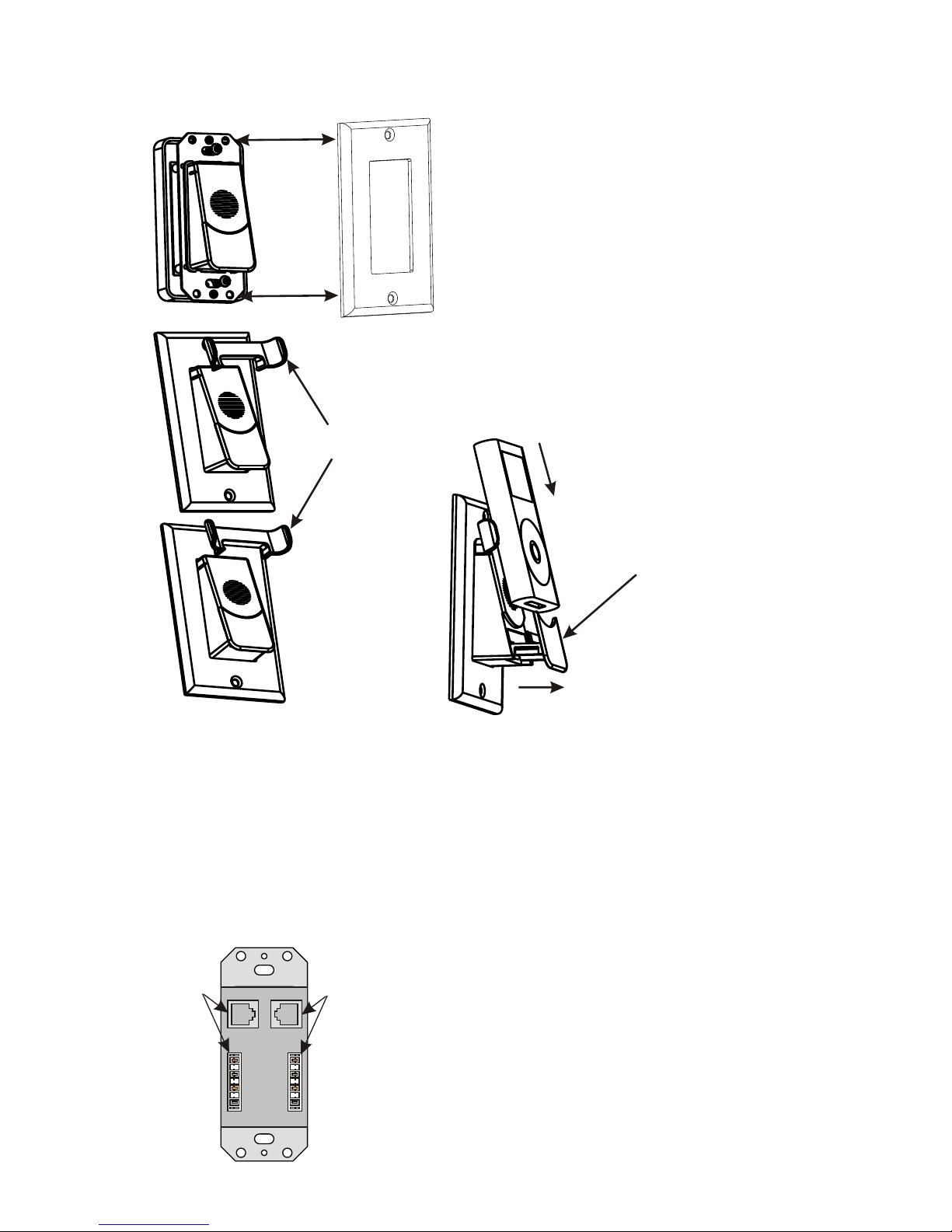
4. Open the slide-out cradle
and dock your iPod.
5. Enjoy your music!
Slide-out Cradle
Connections:
Trouble?
1) Be sure you have connected the CAT5 cable correctly. Note that the
stripe/solid pattern should match the labels on the product. Miss-wiring
can cause distorted sound or prevent the system from working at all!
2) Be sure you have connected the speakers in phase. Follow the label
on the product. Out of phase speakers can rob the system of its bass,
especially when driving dual-voice-coil speakers.
Connection Tips and Troubleshooting
Input/Output ... To simplify installation, the
AB-313 has both 110 and RJ-45 inputs and
outputs. Only one of the inputs and one of the
outputs should be used at a time.
Apple and iPod is are trademarks of Apple, Inc., registered in the U.S.
and other countries.
A-BUS is a registered trademark of LeisureTech Electronics Pty Ltd.
This product may be covered by one of the following patents:
US patent no. 7,181,023, 6,389,139 EP 1004222, AU 739808, NZ
502982.
iBus is a registered trademark of Channel Vision Technology.
Stripping and Connecting CAT5 Wire
Specifications: (typical @25º C)
Operating Voltage : 24±.5VDC
Cable requirements: CAT5 or better
Operating Temperature: -10ºC to +50ºC
Specifications subject to change without notice.
Cat5
1. Place the CAT5 between the blade and the first notch of the J-110 tool.
CAT5 cable should be stripped with a proper stripping tool, such as Channel
Vision’s J-110 tool.
3. Inspect the inner wires for damage.
If any wires are cut start over at step 1.
Check for damage
4. Use any standard 110 punch-down tool to properly seat all wires.
Note: Do NOT use a screwdriver or any other tool that is not specifically
designed for terminating UTP cable. Using improper tools will damage
the connector!
Support Clips
3. Select the appropriate support clip for your iPod.
Note: there are 3 support clips provided to
accommodate standard iPods, the iPod mini, and
the iPod nano.
1. Mount the AB-313 in a low
voltage ring or junction box.
2. Install the trim ring.
Installation
Page 7
7
Apple and iPod is are trademarks of Apple, Inc., registered in the U.S.
and other countries.
A-BUS is a registered trademark of LeisureTech Electronics Pty Ltd.
This product may be covered by one of the following patents:
US patent no. 7,181,023, 6,389,139 EP 1004222, AU 739808, NZ
502982.
iBus is a registered trademark of Channel Vision Technology.
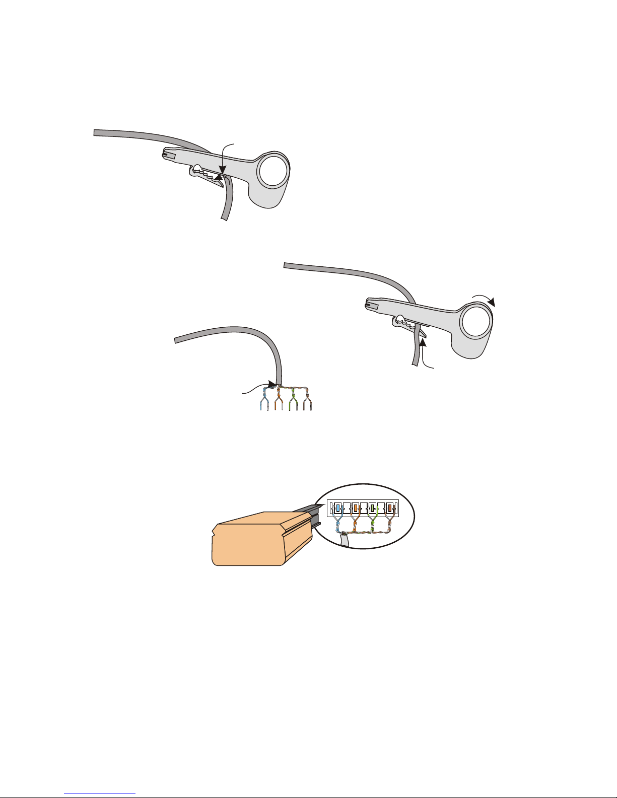
Stripping and Connecting CAT5 Wire
Specifications: (typical @25º C)
Operating Voltage : 24±.5VDC
Cable requirements: CAT5 or better
Operating Temperature: -10ºC to +50ºC
Specifications subject to change without notice.
Blade
Cat5
1. Place the CAT5 between the blade and the first notch of the J-110 tool.
CAT5 cable should be stripped with a proper stripping tool, such as Channel
Vision’s J-110 tool.
Slight
pressure
Rotate
1 turn only
2. Rotate the tool only once around the CAT5. Multiple
turns will cause you to cut into the inner wires.
3. Inspect the inner wires for damage.
If any wires are cut start over at step 1.
Check for damage
4. Use any standard 110 punch-down tool to properly seat all wires.
Note: Do NOT use a screwdriver or any other tool that is not specifically
designed for terminating UTP cable. Using improper tools will damage
the connector!
Page 8

Channel Vision Technology will repair or replace any defect in
material or workmanship which occurs during normal use of this
product with new or rebuilt parts, free of charge in the USA, for two
years from the date of original purchase. This is a no hassle warranty
with no mail in warranty card needed. This warranty does not cover
damages in shipment, failures caused by other products not supplied
by Channel Vision Technology, or failures due to accident, misuse,
abuse, or alteration of the equipment. This warranty is extended only
to the original purchaser, and a purchase receipt, invoice, or other
proof of original purchase date will be required before warranty
repairs are provided.
Mail in service can be obtained during the warranty period by calling
(800) 840-0288 toll free. A Return Authorization number must be
obtained in advance and can be marked on the outside of the shipping
carton.
This warranty gives you specific legal rights and you may have other
rights (which vary from state to state). If a problem with this product
develops during or after the warranty period, please contact Channel
Vision Technology, your dealer or any factory-authorized service
center.
500-177 revB1
www.channelvisio n. co m
234 Fischer Avenue, Costa Mesa, California 92626 USA
(714)424-6500 (800)840-0288 (714)424-6510 fax
email: [email protected]
 Loading...