

Page 1
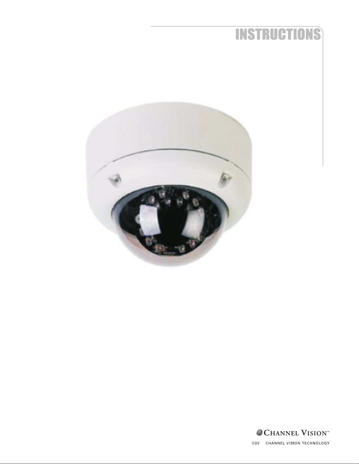
6901
Vandal-ProofIROutdoorWDRDomeCamera
1
2
Page 2

Contents
1. SAFETY PRECAUTIONS ............................................................................... 1
2. INTRODUCTION ........................................................................................... 2
3. FEATURES ..................................................................................................... 3
4. PACKING LIST ............................................................................................... 5
5. NAME and FUNCTION of EACH PART ........................................................ 6
5.1 OSD Button (Menu): ............................................................................ 6
6. INSTALLATION ............................................................................................. 7
6.1 Camera Installation & Operation .......................................................... 7
6.2 Connect to Monitor ............................................................................. 10
6.3 Connect the Power .............................................................................. 11
6.4 Connection Layout ............................................................................. 12
7. OPERATION ................................................................................................. 15
7.1 PELCO Keyboard (or compatible) Operation ..................................... 15
8. SYSTEM SETUP ........................................................................................... 16
8.1 Digital Zoom Operation: ..................................................................... 16
8.2 OSD (On Screen Display) ................................................................... 16
8.3 Sub Menu Description ........................................................................ 17
9. Camera Control Command Protocol ............................................................... 30
9.1 Communication Format ...................................................................... 30
9.2 PC Command ..................................................................................... 32
9.3 Key Code Table .................................................................................. 59
10. SPECIFICATION......................................................................................... 62
The author assumes no responsibility for any errors or omissions that may appear in this
document nor does the author make a commitment to update the information herein.
Page 3

1. SAFETY PRECAUTIONS
CAUTION
RISK OF ELECTRIC SHOCK.
DO NOT OPEN!
CCCCAAAAUUUUTTTTIIIIOOOONNNN ::::
TO REDUCE THE RISK OF ELECTRICAL SHOCK,
DO NOT OPEN COVERS (OR BACK).
NO USER SERVICEABLE PARTS INSIDE.
REFER SERVICING TO QUALIFIED
SERVICE PERSONNEL.
It is advised to read the Safety Precaution Guide through carefully before operating the
product, to prevent any possible danger.
WARNING: Alert the user to the presence of un-insulated “dangerous voltage”.
CAUTION: Alert the user the presence of important operating and maintenance (Servicing)
instructions in the literature accompanying the appliance.
Disposal of Old Electrical & Electronic Equipment (Applicable in the European
Union and other European countries with separate collection systems).
This symbol indicates that this product shall not be treated as household waste. Instead it
shall be handed over to the applicable collection point for the recycling of electrical and
electronic equipment. By ensuring this product is disposed of correctly, you will help
prevent potential negative consequences for the environment and human health. For more
detailed information about recycling of this product, please contact your local city office,
your household waste disposal service or the shop where you purchased the product.
Please be extra careful not to shake the product.
Please avoid places where frequent vibrations or shocks.
Do not install the product in extreme temperature conditions.
Only use the camera under conditions where temperatures are between -10℃ and +50℃. Be
especially careful to provide ventilation when operating under high temperatures.
Do not install the product in an environment where the humidity is high.
Unless the product is waterproof or weatherproof, otherwise it can cause the image quality to be
poor.
Do not expose to strong light (sun rays), as color filters will be discolored.
Do not spill liquid of any kind on the product.
If it gets wet, wipe it dry immediately. Alcohol or beverages can contain minerals that corrode the
electronic components.
If anything abnormal occurs, make sure to unplug the unit, and contact your local dealer.
Page 4
2. INTRODUCTION
This WDR digital image camera uses a high sensitive color Sony 1/3” interline transfer
Charge Coupled Device (CCD) image sensor, producing pictures reaching 650 lines of
horizontal resolution.
Super Wide Dynamic Range technology, capturing both high-luminance and low
luminance subjects under these type of shooting conditions. 3-D Noise Reduction
technology, automatic reduce noise at low light environment, clear picture quality saving
90% hard disk storage space of DVR when using MPEG/ MPEG4/ H.264 compression
after noise reduction. The camera-side initiatively provides mobile detection warnings
offering more comprehensive monitoring of safety protection. Careful planed privacy
zone enables monitoring more at ease.
650TVL
WDR
DNR
Page 5

3
3. FEATURES
High Resolution
CCD Sensor provides high resolution
reaching 650 TVL with advanced and
clear picture quality.
Excellent Sensitivity
High sensitivity, low smear, high
anti-blooming and high S/N ratio.
Wide Dynamic Range (WDR) and
Adaptive Tone Reproduction
High-quality WDR and ATR functions,
perfectly shows the image details
between dark and light. Newly added
environment dynamic detection switch,
enhancing WDR image efficiency.
Day & Night Digital Slow Shutter (DSS)
Mechanic IR cut-filter driving unit with
AE provides change from color to B&W
mode automatically for day and night
24-hour surveillance. Selectable
between manual Day & Night control or
from external input signal Day & Night
control.
Digital Noise Reduction (DNR)
2D/ 3D DNR, realize the clear image at
low light environment, clear picture
quality saving hard disk storage size of
DVR when using MPEG/MPEG4/H.264
compression after noise reduction.
Improve the low light performance.
When in low light, reducing the image
frame refresh rate and increase the
sensitivity of the camera.
Privacy Mask Motion Detection
Privacy image masking with free
position, support up to 15 areas of
privacy masking zone. Privacy area
enlarges with digital zoom-in function.
Camera-site takes the initiative in
providing motion detection alert for a
more comprehensive monitoring and
careful editing of motion detection area.
When there are changes within the
detection area, the camera immediately
issues a warning.
Page 6

4
Lens (C/CS Mount) Extra Connection
Built-in DC-type Vari-Focal lens with
ICR.
Control the camera easy by keyboard/PT
Driver via RS485 interface; Connect the
extra Alarm out to combine with the
Motion Detection function.
OSD Image Control
OSD (On Screen Display) Setup Menu.
Camera tile setup of up to 16 alphanumeric
letters.
Performance: 16x digital zoom, freeze
image, positive/ negative image, mirror
function (left/ right), reverse turn (up/
down), and 180° rotation.
Application
All function can be operated from OSD: WDR (Wide Dynamic Range), ATR
(Adaptive Tone Reproduction), IR OPT (IR Smart), AES (Automatic Electronic
Shutter), AI (Auto Iris), AGC (Auto Gain Control), AWB (Auto White Balance),
BLC (Back Light compensation), DSS (Digital Slow Shutter) and provides the
flickerless mode, and line-lock function.
***Optional
DC 12V
AC 90~240V
Page 7
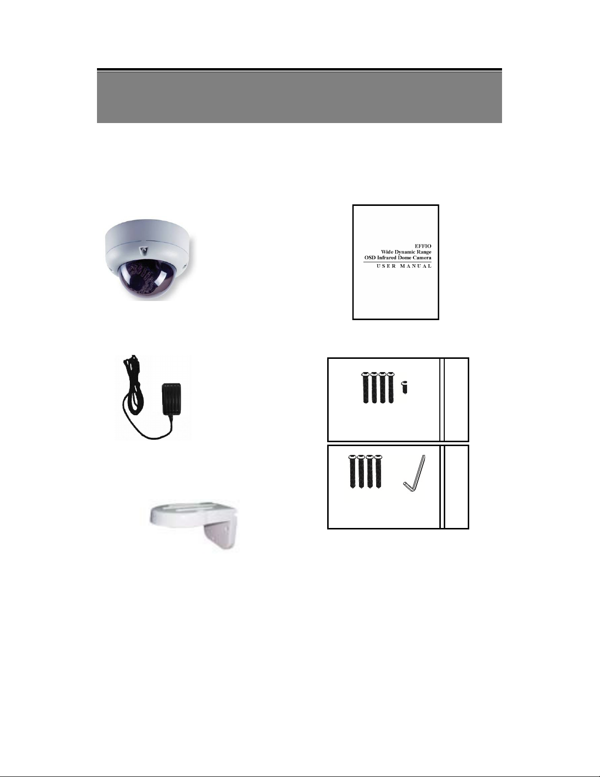
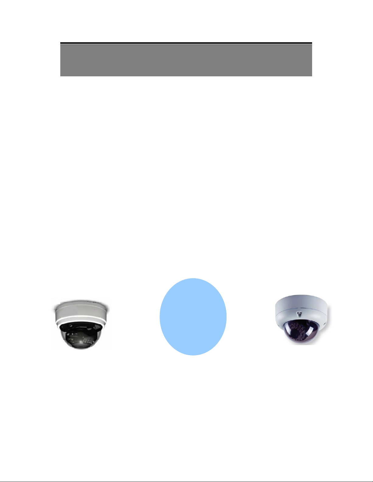
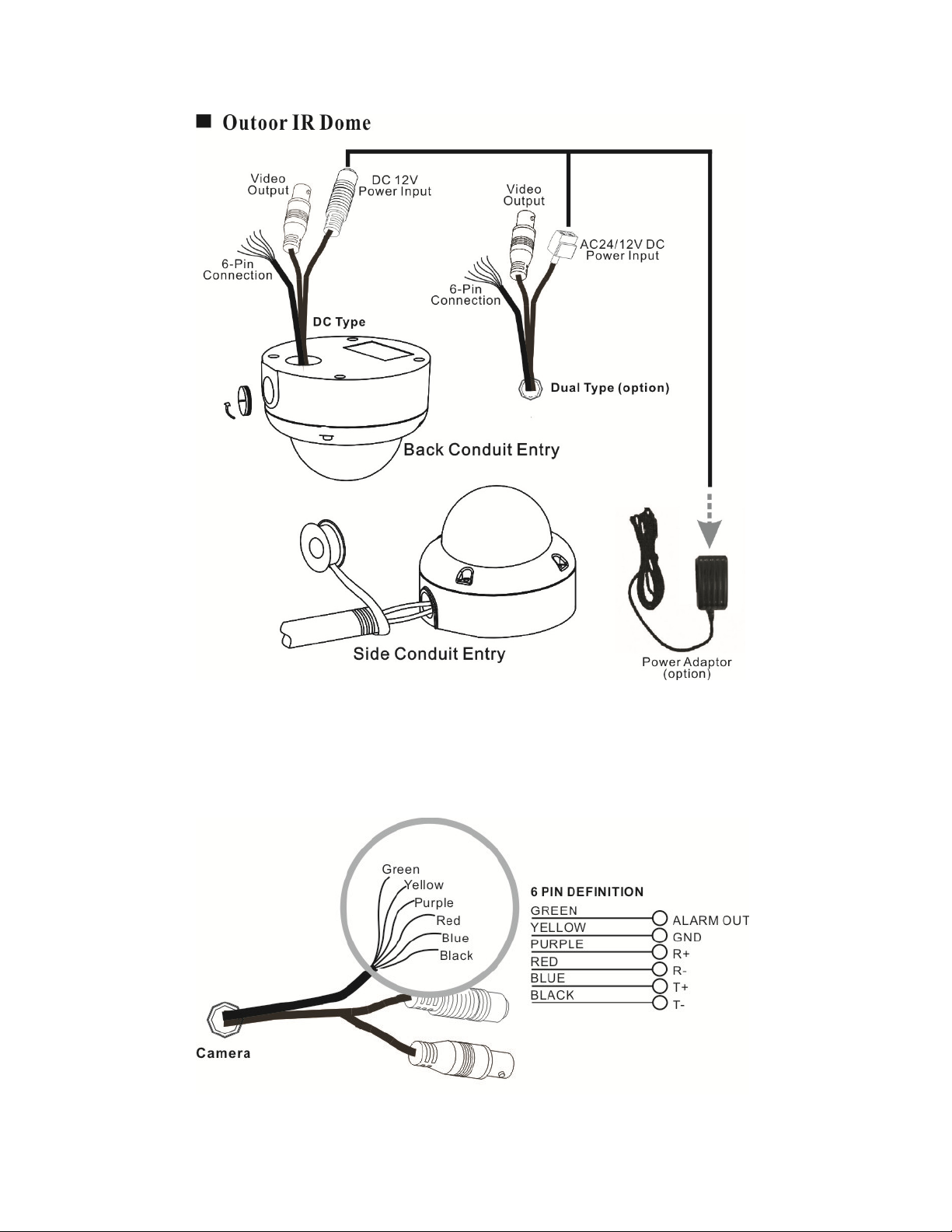
4. PACKING LIST
Outdoor IR
Dome
Indoor IR
Dome
Check and make sure all the items shown below are included in your product package.
If something is missing, contact your dealer as soon as possible.
6901 Dome Camera User’s Manual
Power Adaptor Accessories
5034 (sold separately )
Page 8

6
5. NAME and FUNCTION of EACH PART
5.1 OSD Button (Menu):
No. Name Function
1
UP Digital Zoom-Out or Up direction button
2
DOWN Digital Zoom-In or Down direction button
3
RIGHT
4
LEFT
5
ENTER Enter or Exit setup MENU
To adjust the OSD, remove the dome cover from the main body by gently turning
the cover counter-clockwise to unlock and pull free from the main body. The
OSD buttons can be found on the main body of the dome camera.
Increase Value (
Decrease Value (
++++
----
)
)
Page 9
7
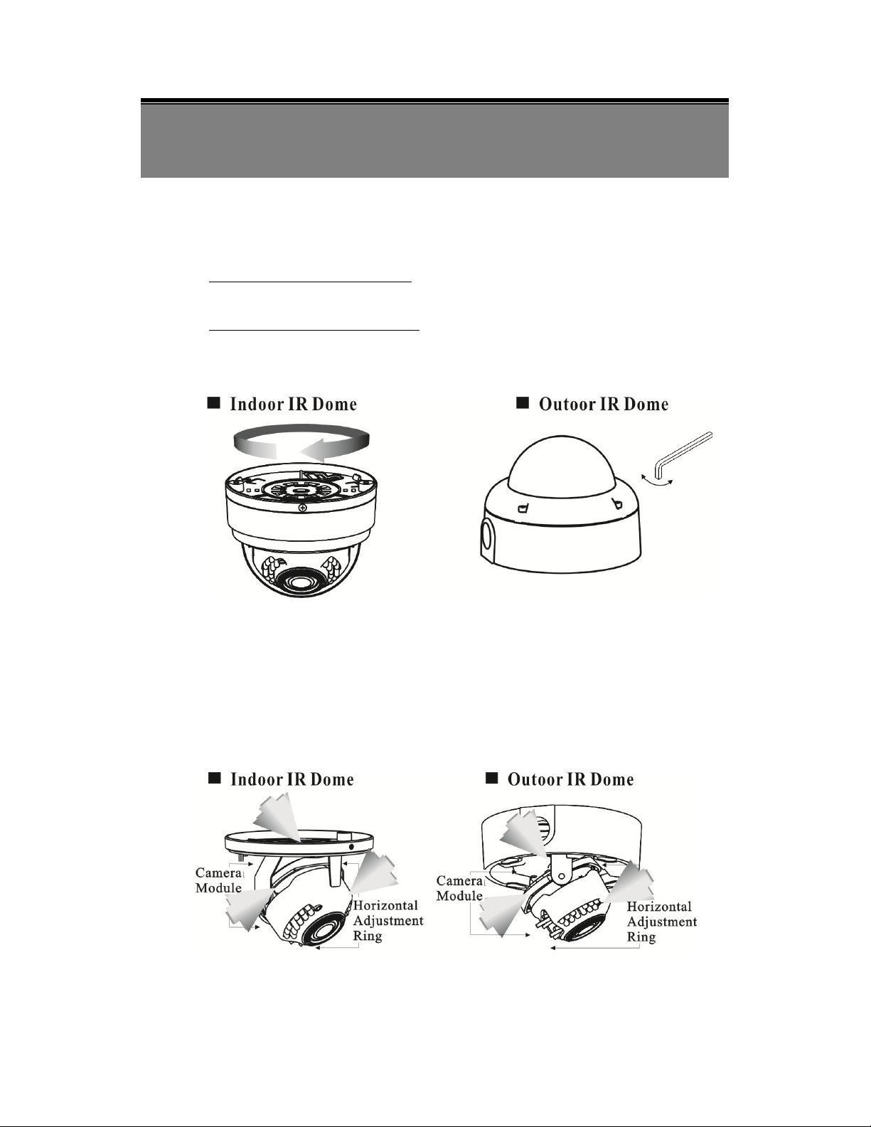
6. INSTALLATION
6.1 Camera Installation & Operation
1.
Removing the Dome Cover
Remove the indoor dome cover from the main body by gently turning the
cover counter-clockwise to unlock and pull free from the main body.
Remove the outdoor dome cover using the provided L-Wrench, loosen the
screws securing the temper-resistant housing cover (with the screws still
attached on the cover) to unlock the cover from the main body.
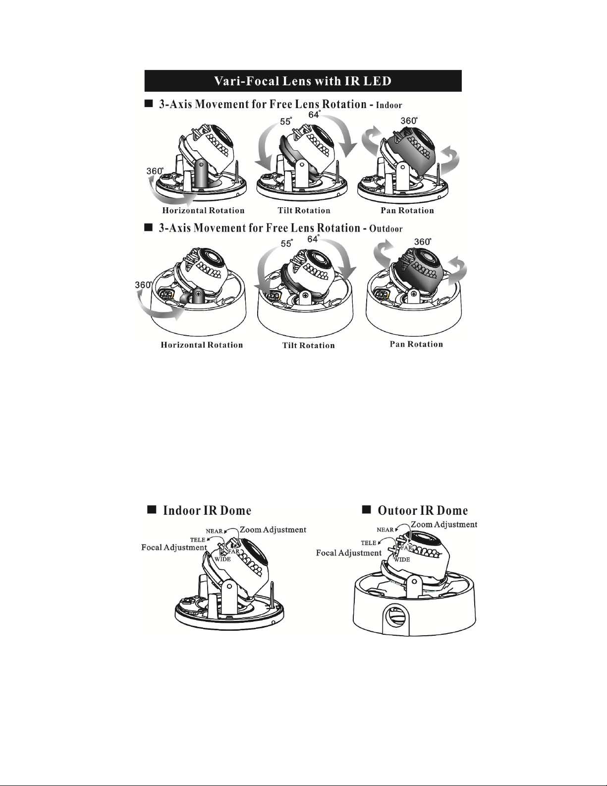
2. Camera Image Adjustment
You can adjust camera to any direction by using Pan, Tilt, and Rotate the
mechanism.
Pan Base moves by 360° on the whole.
Tilt Base covers total 119° angle (64° to one side and 55° to the other side).
Angle range of Rotate Base is 360°.
Page 10
8
<Note> This product is not suitable for horizontal 360° continuous rotation.
3. Adjusting the Vari-Focal Lens
Loosen the Zoom lever counter-clockwise a little, and then rotate the Zoom
lever to obtain the best image view.
Loosen the Focus lever counter-clockwise a little, and then rotate the Focus
lever to obtain the optimum picture quality.
Re-tighten the Zoom lever and Focus lever after adjustment.
Page 11
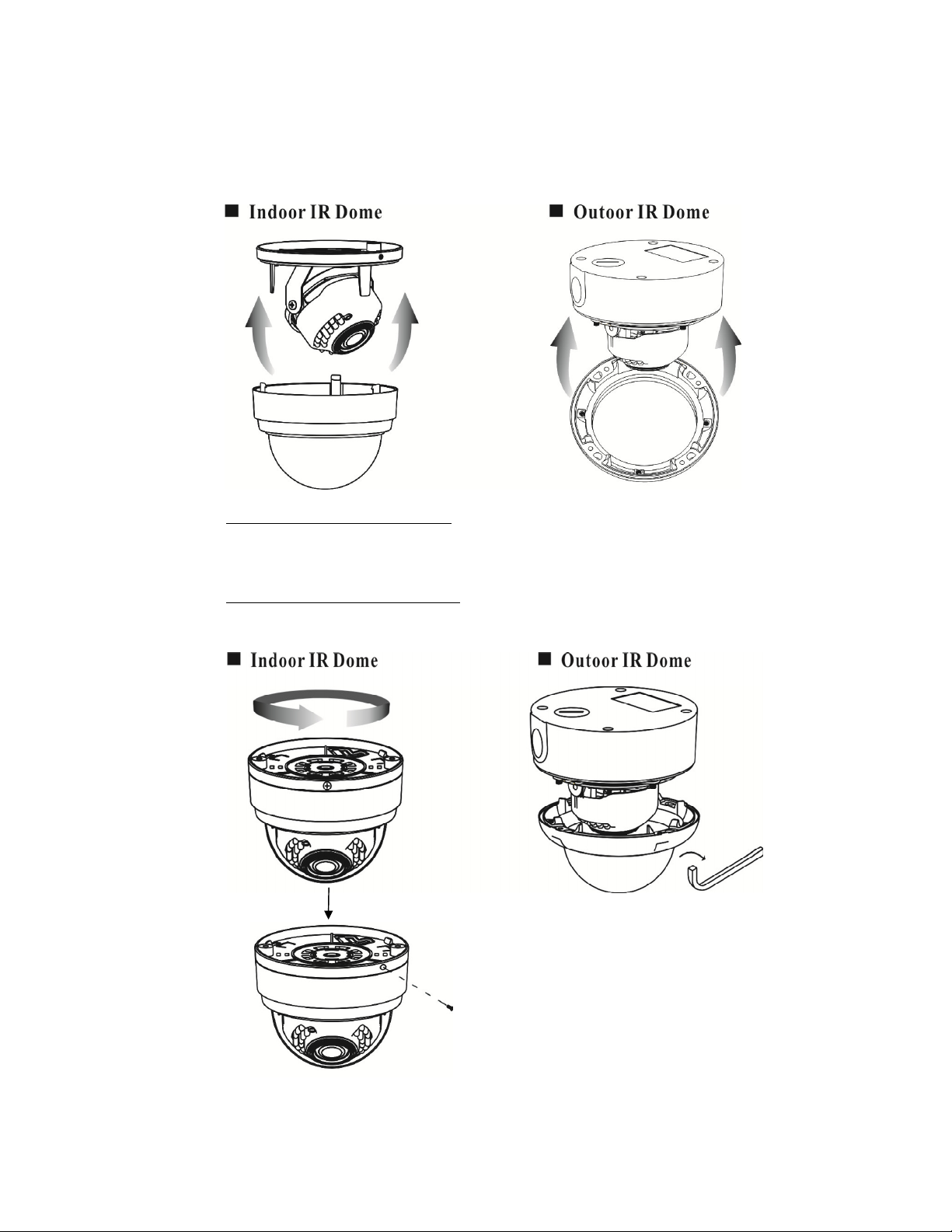
4. Attaching the Dome Cover
After all necessary adjustment has been made reinstall the dome cover to the
main body.
Reinstall the indoor dome cover and the main body by turning the dome
clockwise until it locks in place. To prevent unpredictable damage and
burglary, lock-up the dome by using the countersunk head screw.
Reinstall the outdoor dome cover and the main body by using the provided
L-Wrench to fasten the cover to the main body.
Page 12
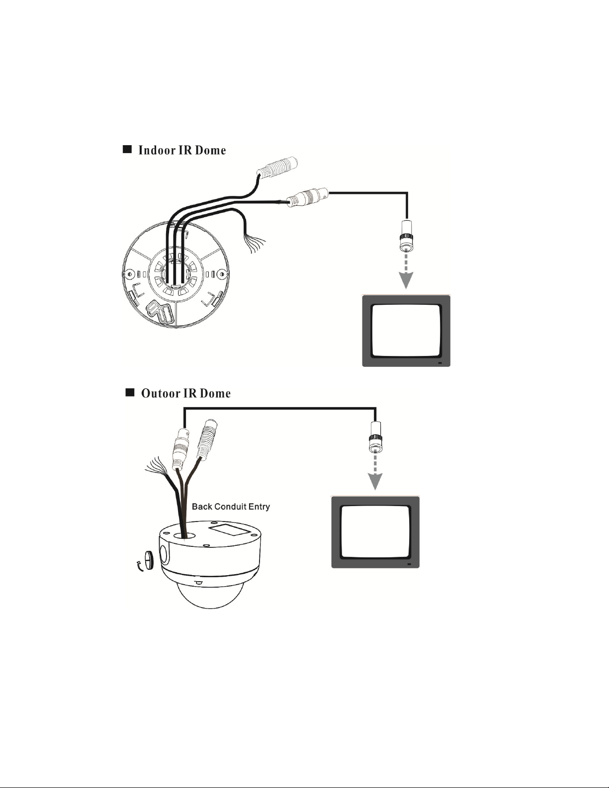
6.2 Connect to Monitor
Connect the Video-out port of the camera to a monitor. As the connecting method varies
depending on the instrument, therefore refer to the manual supplied with the instrument
for more information.
10
Page 13
11
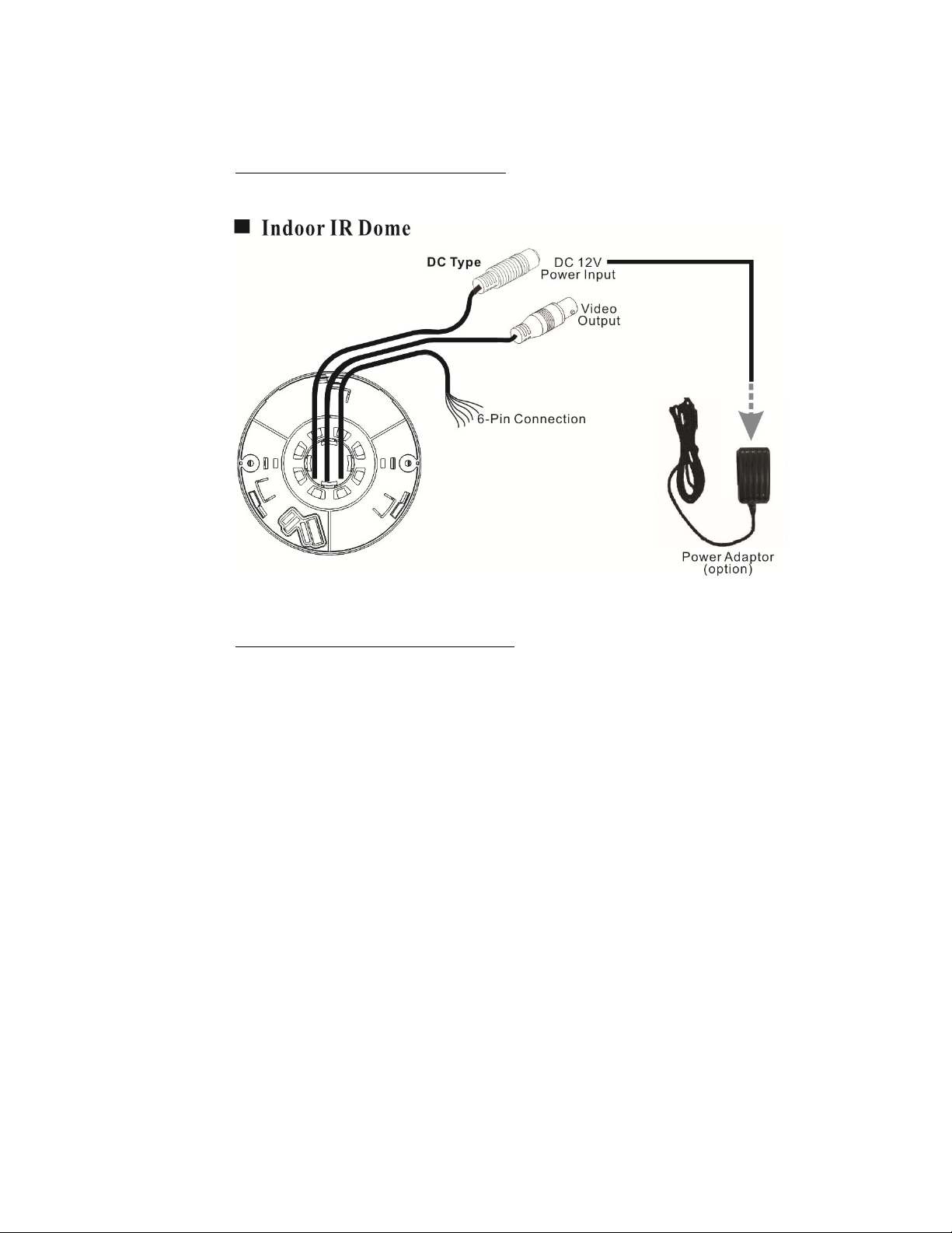
6.3 Connect the Power
Connect the indoor dome video output to a 75 Ohms type coaxial cable and
the DC-Jack or AC/ DC-Terminator to the power source.
<Note> Power adapter is sold separately.
Connect the outdoor dome video output to a 75 Ohms type coaxial cable and
the DC-Jack or AC/ DC-Terminator to the power source. When using the
side conduit cabling, it is suggested to use a metal to cover over the cables
to prevent external damage and as weatherproof prevention, please wined
the weatherproof adhesive tape (P.T.F.E. THREAD SEAL TAPE) onto the
metal cover before installation.
Page 14
<Note> Power adapter is sold separately.
6.4 Connection Layout
To connect the keyboard and alarm, please follow the setup guide shown below:
12
Page 15
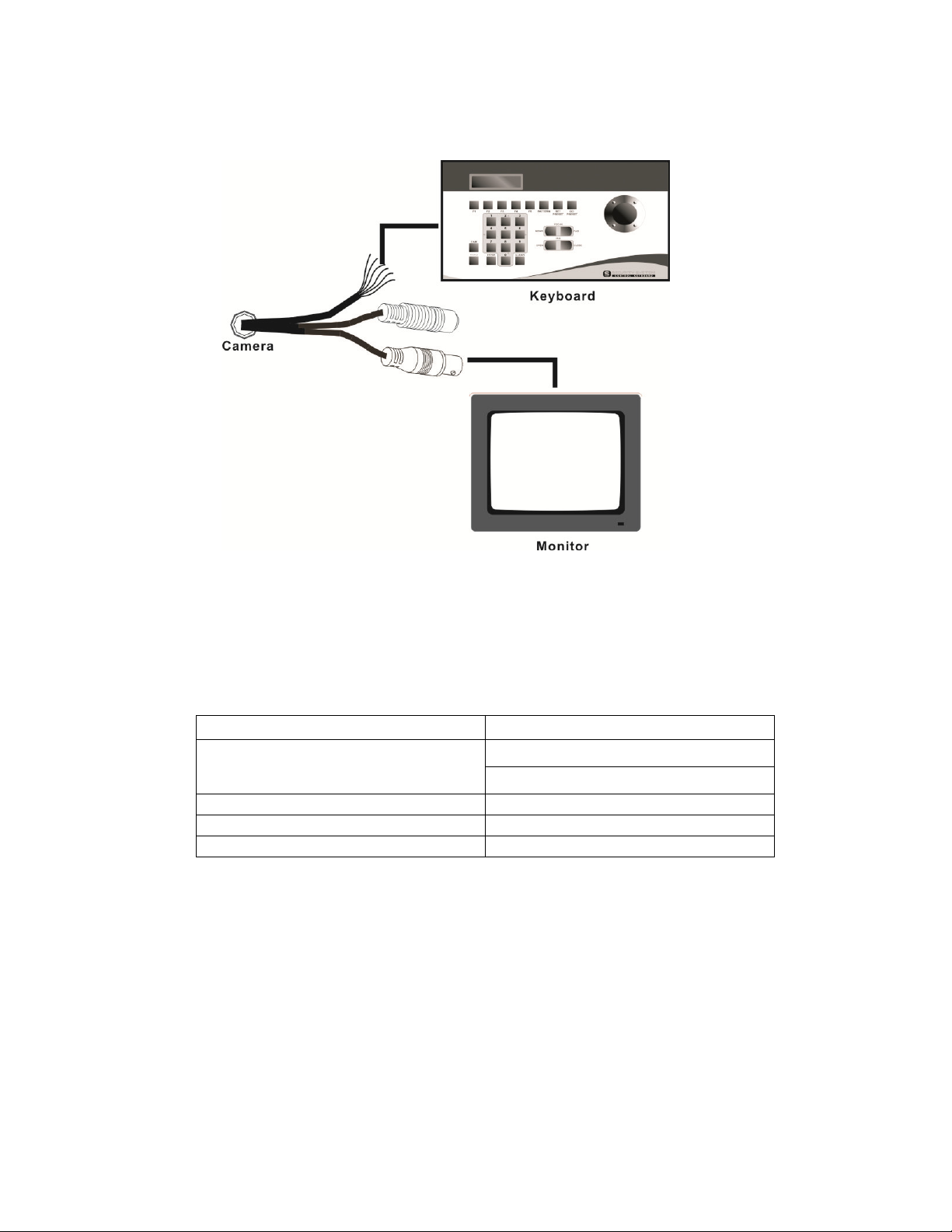
6.4.1 Connecting a Keyboard
0 ~ 253 for P protocol
PELCO Keyboard (or compatible) Installation
RS-422 interface is used for communicating PELCO keyboard. Refer to Fig. 1;
connect R+ of the camera to T+ of the PELCO keyboard. Connect R- of the
camera to T- of the PELCO keyboard.
User could adjust Camera ID via rear panel keys or via remote commands.
Protocol, Speed and Parity should only be adjusted via rear panel keys.
Communication
CAMERA ID
PROTOCOL PELCO
SPEED 2400, 4800, 9600, 19200
PARITY NONE
The speed of camera should be the same as the speed of the keyboard.
Adjusted function is only effective, after exiting the OSD setup menu.
<Note>
Maximum cable distance for RS-485 communication over 24-gauge wire is 4,000
feet (1,219 m). Recommend using shielded twisted pair cable that meets the basic
requirements for EIA RS-485 applications.
Setting
1 ~ 255 for D protocol
13
Page 16
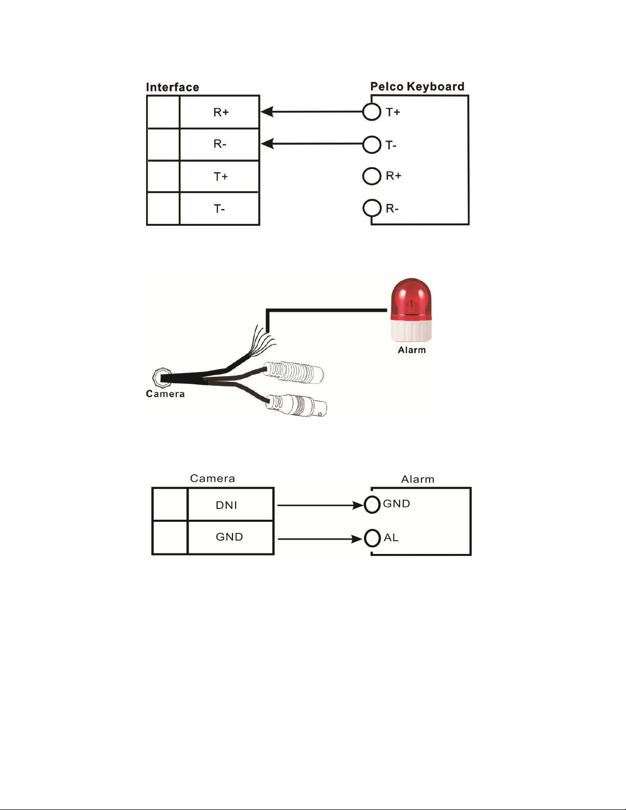
Fig.1
6.4.2 Connecting the Alarm
Alarm Installation
Connect GND and AL of the camera to the GND and AL of the alarm.
<Note> The alarm is triggered by motion detection.
14
Page 17

7. OPERATION
Enter 95; Hold the PRESET key (approximately five
1. Mount the camera on the mounting bracket by using the hole on the top or bottom
of the camera, and by using the enclosed mounting block, secured by 2 screws.
2. Connect the video output to the monitor or other video device via a 75 Ohms type
coaxial cable.
3. Power Input Terminal (Dual Power): the camera accepts both AC 24V and DC 12 V
power sources (non-polarity).
7.1 PELCO Keyboard (or compatible) Operation
Normal Display Mode
PELCO Keyboard Camera Function
OPEN LEVEL +
CLOSE LEVEL Twist Joystick clockwise or Zoom In Zoom Tele
Twist Joystick counterclockwise or Zoom Out Zoom Wide
NEAR None
FAR None
Move Joystick Left None
Move Joystick Right None
Move Joystick Up None
Move Joystick Down None
seconds) until the main menu appears on the screen.
<Note>
CLOSE / OPEN adjustments are required to meet the EXPOSURE MODE settings, size
LEVEL is only adjustable when the option is under [WDR], [BLC USER], and [NORMAL].
OSD Setup Menu Mode
PELCO Keyboard Camera Function
OPEN Sub Menu Enter
CLOSE Sub Menu Exit
NEAR Cursor Up
FAR Cursor Down
Move Joystick Left Decrease (-)
Move Joystick Right Increase (+)
Move Joystick Up Cursor Up
Move Joystick Down Cursor Down
Twist Joystick clockwise or Zoom In None
Twist Joystick counterclockwise or Zoom Out None
<Note>
Please refer to PELCO Keyboard (or compatible) manual for more information.
Accessing OSD Main Menu
15
Page 18

8. SYSTEM SETUP
8.1 Digital Zoom Operation:
Under normal display (before entering the OSD menu), use (T)/ (W) button to
control the digital zoom (zoom range: 1 x ~ 16 xs).
8.2 OSD (On Screen Display)
Main Menu Display
MAIN MENU VERSION
EXPOSURE
DAY/NIGHT
WHITE BALANCE
PRIVACY
EFFECT
MOTION DETECT
COMMUNICATION
EXIT SAVEALL DEFAULT
Main Menu Setup
In order to display the setup menu on the screen, set the menu command or press the
button panel.
Use (T)/ (W) control buttons to select each item.
Use ◄
(
----
)/ ►(
++++
) control buttons to change the data.
Use MENU control button to ENTER/ EXIT the menu display.
AUTO
OFF
16
Page 19

8.3 Sub Menu Description
8.3.1 EXPOSURE Setup
EXPOSURE
(1) WDR:
(2) SHUTTER:
(3) HLC/ BLC:
This function could be enabled when WDR function is off.
Set the mode to OFF/ BLC MANUAL/ BLC SMART/ HLC.
WDR
SHUTTER
BACKLIGHT
SHUTTER AGC
NOISE REDUCTION
IRIS SPEED
DIS
DEFAULT
MANUAL
OFF
LOW
031
OFF
RETURN
This function is used for changing the AE mode.
Set the mode to Normal, ATR-EX, WDR
CONTRAST
This function is used for ATR-EX & WDR mode setting.
Set contrast to Low/ Mid. Low/ Middle/ Mid. High/ High.
LEVEL
This function is used for ATR-EX & WDR mode setting.
Set contrast to Low/ Mid. Low/ Middle/ Mid. High/ High.
AUTO SHUTTER MODE:
HIGHT LUMINANCE
Set the Brightness to 0 ~15 (Default Setup: 3).
LOW LUMINANCE
Set the DSS to OFF, 2~20FLD, 40FLD, 80FLD, 160FLD,
256FLD, 512FLD (Default Setup: OFF).
Manual SHUTTER SPEED MODE:
Set the speed (NTSC: 1/60, PAL: 1/50), (NTSC: 1/100FLK, PAL:
1/120FLK), 1/250, 1/500, 1/1000, 1/2000, 1/4000, 1/10000, 1/20000,
1/50000, 1/100000 sec.
HIGH LUMINANCE
Set the brightness to 0 ~15 (Default Setup: 3).
17
Page 20

Back Light Compensation (BLC) is ON:
BLC could emphasize the luminance of the BLC Area according to the
BLC Level.
Manual/ SMART BLC:
MANUAL
The Manual BLC function enables manually setup of BLC on parts of
image or the whole image.
SMART
The Smart BLC function through DSP, according to the backlight
environment auto calculates the backlight compensation to assure
explicit and accurate image both in dark or strong backlight
environment.
HLC SET
The High Light Compensation (HLC) function enhances the visibility
of license plates and other objects by performing suppression
processing and mask processing on strong light sources
(automobile headlights, etc.) in dark locations.
EXPOSUREHLC
HLC
CLIP LEVEL
SCALE
DEFAULT
RETURN>
000
010
HLC CLIP LEVEL
Sets the clip level used for luminance mask.
Adjust the level from 0 MIN to 50 MAX., lower the value darker the
luminance mask (grey) and higher the value lighter the luminance
mask (white).
HLC SCALE
Sets the AE exposure correction in HLC mode.
18
Page 21

Adjust the level from 0 MIN to 15 MAX (Default Value: 13).
EXPOSURE BLC
BLC
LEVEL
AREA SELECT
TOP
BOTTOM
LEFT
RIGHT
DEFAULT
RETURN>
000
CENTER
NA
NA
NA
NA
BLC LEVEL SET
This function is valid to BLC MANUAL mode.
Adjust the level from 0 MIN to 15 MAX.
BLC AREA SET
This function is valid to BLC MANUAL mode.
Define the main object area that is under exposure based on the
average luminance of the whole image.
AREA:Setup to “BLC”, the area is set as BLC area and under
manual mode ○1 CENTER ○2 TOPS ○3 TOPL ○4 BOTTOMS ○5
BOTTOML
6 LEFT ○7 RIGHT
○
Set BLC area to USER to manually setup the BLC area.
19
Page 22

(4) SHUTTER AGC:
Adjust the level from LOW*/ MIDDLE/ HIGH.
(5) NOISE REDUCTION:
Set the 2D-NR to OFF/ LOW/ MID-LOW/ MIDDLE*/ MID.HIGH/
HIGH.
Set the 3D-NR to OFF/ LOW/ MID-LOW/ MIDDLE*/ MID.HIGH/
HIGH.
(7) IRIS SPEED:
Set the IRIS SPEED from 0 ~ 31* ~ 255.
When aperture blinking occurs, adjust the IRIS SPEED to improve the
blinking result.
(6) DIS:
Set the digital image stabilizer mode to OFF* or ON.
(7) DEFAULT:
If default is entered, all exposure functions will be changed to the factory
default setting.
(8) RETURN:
Exit the Exposure setup menu and return to the main menu.
8.3.3 DAY/NIGHT Setup:
DAY/ NIGHT
DAY/ NIGHT
DEFAULT
RETURN
(1) DAY/ NIGHT:
This function is used for Day & Night control mode setting.
Set the mode to EXTERNAL >*, DAY, NIGHT or AUTO mode.
IR OPT function is applicable only under EXTERNAL mode.
Sub menu of AE mode could be set to the following parameters.
AUTO
20
Page 23

AUTO DAY TO NIGHT
AUTO NIGHT TO DAY
AUTO DELAY CNT
AUTO BURST
EXTERNAL IR OPT
<Note>
EXTERNAL mode must be switched to NIGHT mode to enable IR OPT function.
(2) DEFAULT:
(3) RETURN:
Adjust the threshold level from 156 to 895 to switch mode from day
to night (Default Setup: 500*).
When SHUTTER AGC is set to LOW, the threshold level will be
from 349~895
When SHUTTER AGC is set to MID, the threshold level will be
from 253~895
When SHUTTER AGC is set to HIGH, the threshold level will be
from 156~895
Adjust the threshold level from 156 to 895* to switch mode from
night to day (Default Setup: 700*).
When SHUTTER AGC is set to LOW, the threshold level will be
from 349~895
When SHUTTER AGC is set to MID, the threshold level will be
from 253~895
When SHUTTER AGC is set to HIGH, the threshold level will be
from 156~895
Adjustable level from 0 to 60 seconds (Default Setup: 5*).
Delay time is used for turning the filter.
Adjust the mode to OFF or ON*.
Adjust the mode to OFF* or ON (Set to ON to select between
CENTER or AUTO mode).
Adjustable level from 1 to 31 (Default Setup: 3*).
Setup ATR-EX to ON or OFF*.
If default is entered, all DAY/ NIGHT functions will be changed to the
factory default setting.
Exit the DAY/ NIGHT setup menu and return to the main menu.
21
Page 24

8.3.4 AUTO WHITE BALANCE Setup:
AUTO WHITE BALANCE
MODE
DEFAULT
ATW
RETURN
(1) AWB MODE:
This function is used for changing the WB mode.
Set the mode to ATW*, Indoor, Outdoor, Manual, Push Lock,
Anti-CR.
ATW: WB color temperature range = 2500°K ~ 8000°K.
Manual WB: Adjust Red and Blue gain to perform a desired White
Balance.
PUSH LOCK Set the WB mode to Push Lock
Anti-CR: Set the WB mode to Anti-CR. WB color temperature range =
3800°K~6000°K.
Sub menu of Manual> mode could be set the following parameters.
R GAIN (Red Gain)
This function is valid only when WB MODE is set to MANUAL.
Adjust the level from 0 to 255 (Default Setup: 0*).
B GAIN (Blue Gain)
This function is valid only when WB MODE is set to MANUAL.
Adjust the level from 0 to 255 (Default Setup: 0*).
(2) PUSH LOCK:
This function is valid only when WB MODE is set to PUSH LOCK.
Enable this mode to perform auto tracing action. Disable this mode
to preserve the final auto tracing action.
(3) DEFAULT:
If default is entered, all AWB function will be changed to the factory
default setting.
(4) RETURN:
Exit the AWB setup menu and return to the main menu.
22
Page 25

8.3.5 PRIVACY Setup:
PRIVACY
AREA SELECT
MODE
POSITION
COLOR
TRANSP.
MOSAIC
DEFAULT
RETURN
1/15
OFF
NA
NA
NA
NA
(1) AREA SELECT:
Select the mask from 1 to 15.
The number is which current setting of mask.
(2) MODE:
Adjust the mode to OFF* or ON.
(3) POSITION:
Adjust the position of the mask area by top, bottom, left and right fields.
This function is available only when mask function is enabled.
(4) COLOR:
Set the color to WHITE, BLACK*, RED, GREEN, BLUE,
YELLOW, CYAN or MAGENTA.
This function is available only when mask function is enabled.
(5) TRANSP.:
Set the transparency to 0.00, 0.5, 0.75 or 1.0*.
This function is available only when mask function is enabled.
(6) MOSAIC:
Set mosaic effect to ON or OFF*.
This function is available only when mask function is enabled and
transparency ≠ 1.0.
(7) DEFALUT:
If default is entered, all PRIVACY functions will be changed to the
factory default setting.
(8) RETURN:
23
Page 26

Exit the PRIVACY setup menu and return to the main menu.
8.3.6 EFFECT Setup:
EFFECT
DISPLAY
COLOR
VIEW MODE
POSI/ NEGA
MIRROR
FREEZE
SYNC
WPS
IRIS ADJ
LANGUAGE
CRT>
POSI
OFF
OFF
INT
ENGLISH
DEFAULT
RETURN
EFFECT→ [DISPLAY]
DISPLAY
TITLE ID
CAMERA ID DISP
ZOOM RATIO DISP
MOT/ ALM DISP
AE/ AWB DISP
DEFAULT
ON
ON
ON
ON
ON
RETURN
(1) DASPLAY:
This function is used for on screen display settings.
TITLE ID SET
Select the mode ON*/ OFF.
The Title ID can be edited (Please avoid the following display
locations: CAMERA ID/ZOOM RATIO/MOT ALARM/AE AWB
DISP.)
24
Page 27

Zoom
CAMERA ID DISP SET
Select the mode ON*/ OFF.
ZOOM RATIO DISP SET
Select the mode ON*/ OFF.
MOT/ ALM DISP SET
Select the mode ON*/ OFF.
AE/ AWB DISP SET
Select the mode ON*/ OFF.
DEFAULT
Return to default setup.
RETURN
Return to previous status.
Normal AWB
M
1 CAMID:1 ZOOM CAMERA
ID
Title
(2) COLOR:
BRIGHTNESS ADJUST SET
Adjust the level from 0 ~100*~ 255.
CONTRAST ADJUST SET
Adjust the level from 0 ~32*~63.
SHARPNESS ADJUST SET
Adjust the level from 0 ~8*~15.
HUE ADJUST SET
Adjust the level from 0 ~75*~255.
STATUARATION SET
Adjust the level from 0 ~3* to 10.
DEFAULT
Return to default setup.
RETURN
Return to previous status.
(3) VIEW MODE
This function is used for adjusting the display setting of LCD or
25
Page 28

CRT*.
Set the grammar profile for your monitor.
(4) POSI/ NEGA
This mode is used for changing the color and luminance to negative.
Select the mode NEGA or POSI*.
(5) MIRROR
This function allows mirroring the image vertically, horizontally, or
both.
Select the mode OFF*, V-FLIP, H-FLIP, or HV-FLIP.
(6) FREEZE
This function allows freezing the screen.
Select the mode ON, OFF*.
(7) SYNC:
Under the LL mode, the AC power supply and VD signals of the
camera are synchronized (V-PLL). The frequency of the power
supply which can be used by the LL mode is 60Hz applying NTSC
system and 50 Hz applying PAL system.
Select the mode LL/ INT*.
<Note>
1. When the power is DC 12V, the SYNC menu is fixed to the INT mode
(cannot be switched to Line Lock mode.).
2. When switched to Line Lock mode, use “SHIFT UP” and “SHIFT
DOWN” to adjust the phase of the VD, and after adjusting to the new VD
phase it will be switched to OFF.
(8) WPC
This function detects during normal shooting the white pixels which
arise after shipment from the factory and which have not been
registered by the static detection function, and it provides
compensation with no limits set on the number of white pixels.
Select the mode ON, OFF*.
(9) IRIS ADJ
When replacing the lens, face the camera toward the light, and then start the
option “ADJ”. Message “Wait…” means that adjustment is in progress,
about 40 seconds afterward a message “Success!!” appears indicates that
the adjustment has been completed. When the message “Time Out” or
“ADJ ERR” appears indicates that the adjustment has failed.
(10) LANGUAGE:
This function allows changing the language of OSD.
26
Page 29

Select the mode ENGLISH,
(11) DEFAULT:
If default is entered, all EFFECT functions will be changed to the
factory default setting.
(12) RETURN:
Exit the EFFECT setup menu and return to the main menu.
<Note>
Do not precede IRIS ADJ function when replacing Manual Lens.
8.3.7 MOTION DETECT setup:
MOTION DETECT
简体
中文
, or
繁體中文
.
BLOCK DISP
DETECT SENE
DURATION
ALARM OUT
DEFAULT
RETURN
(1) BLOCK DISP:
Select the motion block display ON/ OFF*.
(3) DETECT SENSE:
Adjust the sensitivity level from 1~100*~127 MAX.
(4) DURATION:
Adjust the duration time of alarm output from 5S*, 10S, 15S, 20S, 30S,
1M, 2M, 3M, 4M, and 5M,.
(5) ALARM OUT:
Select the alarm output ON/ OFF* when motion is detected.
(7) DEFALUT:
If default is entered, all MOTION DETECT functions will be changed to
the factory default setting.
OFF
100
5 S
OFF
27
Page 30

(8) RETURN:
Exit the MOTION DECTECT setup menu and return to the main menu.
8.3.8 COMMUNICATION setup:
COMMUNICATION
CAMERA ID
BAUD RATE
PARITY
DEFAULT
RETURN
001
9600
NONE
(1) CAMERA ID:
To connect large amount of cameras, identification number is
assigned to each camera for camera control (000 ~ 255: total numbers
of ID are 256).
This function can only be setup by using the ID commands (Please
refer to 7. Camera Control Command Protocol).
(2) BAUD RATE:
This function allows speed of serial interface setup.
(3) PARITY:
This function allows parity of serial interface setup.
(4) DEFALUT:
If default is entered, all COMMUNICATION functions will be changed
to the factory default setting.
(5) RETURN:
Exit the PRIVACY setup menu and return to the main menu.
<Note>
Communication function is effective only when the above (1) ~ (3) function item
setups has been completed.
28
Page 31

8.3.9 EXIT Setup:
Exit the OSD menu and enter the normal display.
8.3.10 SAVE ALL Setup:
Saving the current configuration to flash.
Set this function to OFF and nothing will be written.
8.3.11 DEFAULT Setup:
If default is entered, all functions will be changed to factory default
settings.
* Letters in BOLD: Default Mode
29
Page 32

9. Camera Control Command Protocol
(For RS-232, RS-422, and RS-485)
9.1 Communication Format
Communication specification (Default)
Communication speed: 9600 BPS
Start bit: 1
Data bits: 8
Parity: None
Stop bit: 1
The communication data format from PC to Camera
Data of total 6 bytes is transmitted from PC to camera.
Format:
Byte1 Byte2 Byte3 Byte4 Byte5 Byte6
0xC5 Code1 Code2 Code3 CAM_ID C.S.
Description: (Refer to 7.2 PC Command)
(a) Byte 1: Camera realizes the protocol comes from the PC.
(b) Byte 2: The data is changeable according to the PC Command.
(c) Byte 3: The data is changeable according to the PC Command.
(d) Byte 4: The data is changeable according to the PC Command.
(e) Byte 5: Camera’s ID (Identification) number to communicate (0 ~ 255).
It will be impossible to communicate when there’s a difference
between the value of CAM_ID and the given value of the
Camera’s ID.
(f) Byte 6: The value of Check Sum from ‘Byte 1’ to ‘Byte 5’.
Ex.: In case of transmission, ‘0xC5, 0x5F, 0x0C, 0x00, 0x00‘
0xC5 + 0x5F + 0x0C + 0x00 + 0x00 = 0x130
Therefore, C.S. = 0x30
30
Page 33

The communication data format from Camera to PC
Data of total 9 bytes is transmitted from Camera to PC.
Format:
Byte1 Byte2 Byte3 Byte4 Byte5 Byte6 Byte7 Byte8 Byte9
0xC5 Code1 Code2 Code3 Data1 Data2 Data3 Data4 C.S.
Description: (Refer to 7.2 PC Command)
(a) Byte 1: Camera is realized the protocol comes from PC.
(b) Byte 2: Byte 1 data is received from PC.
(c) Byte 3: Byte 2 data is received from PC.
(d) Byte 4: Byte 3 data is received from PC.
(e) Byte 5: The data is changeable according to the PC Command.
(f) Byte 6: The data is changeable according to the PC Command.
(g) Byte 7: The data is changeable according to the PC Command.
(h) Byte 8: The data is changeable according to the PC Command.
(i) Byte 9: The value of Check Sum from ‘Byte 1’ to ‘Byte 8’.
The computing method is the same as “Byte6 of the
communication from PC to Camera“.
31
Page 34

9.2 PC Command
Exposure Mode Setting
Set the mode of Exposure according to AEmodeCNT.
PC → Camera
0xC5 0xAA 0x60 AEmodeCNT CAM_ID C.S.
Camera → PC
0xC5 0xAA 0x60 AEmodeCNT 0x60 0xXX 0xXX 0xXX C.S.
AEmodeCNT: The counter for setting Exposure mode
1. In case of AEmodeCNT = 0x00, the Exposure mode becomes an “Normal”
mode.
2. In case of AEmodeCNT = 0x01, the Exposure mode becomes an “ATR-EX”
mode.
3. In case of AEmodeCNT = every other value, the Exposure mode remains
unchanged.
BACKLIGHT Level Read
Read the current BACKLIGHT level of Camera.
PC → Camera
0xC5 0xAA 0x61 0x00 CAM_ID C.S.
Camera → PC
0xC5 0xAA 0x61 0x00 BL_level 0xXX 0xXX 0xXX C.S.
BL_level: This is a value of the camera for controlling BACKLIGHT level.
Adjust BACKLIGHT level
Adjust current BACKLIGHT level of Camera.
PC → Camera
0xC5 0xAA 0x62 BL_level CAM_ID C.S.
Camera → PC
0xC5 0xAA 0x62 BL_level 0x62 0xXX 0xXX 0xXX C.S.
BL_level: This is a value to adjust BACKLIGHT level of camera.
32
Page 35

White Balance Mode Setting
Set the mode of White Balance according to WB_CNT.
PC → Camera
0xC5 0xAA 0x65 WB_CNT CAM_ID C.S.
Camera → PC
0xC5 0xAA 0x65 WB_CNT 0x65 0xXX 0xXX 0xXX C.S.
WB_CNT: This is an index counter to change the mode of White Balance
1. In case of WB_CNT = 0, the mode of White Balance becomes “AUTO” mode.
2. In case of WB_CNT = 1, the mode of White Balance becomes “Anti-CR”
mode.
3. In case of WB_CNT = 2, the mode of White Balance becomes “INDOOR”
mode.
4. In case of WB_CNT = 3, the mode of White Balance becomes “OUTDOOR”
mode.
5. In case of WB_CNT = 4, the mode of White Balance becomes “MANUAL”
mode.
6. In case of WB_CNT = 5, the mode of White Balance becomes “PUSH AUTO”
mode.
7. In case of WB_CNT = every other value, the mode of White Balance remains
unchanged.
Camera ID Display Mode ON/ OFF Toggle control
Switch the display mode of camera ID (ON/ OFF).
PC → Camera
0xC5 0xAA 0x6A 0x00 CAM_ID C.S.
Camera → PC
0xC5 0xAA 0x6A 0x00 0x6A 0xXX 0xXX 0xXX C.S.
Caution: If the Camera ID is “OFF” mode, then the Camera ID is not
displayed.
Zoom Lens Position Read
Read the current position value of Zoom lens & Digital Zoom MAG data.
PC → Camera
0xC5 0x36 0x00 0x00 CAM_ID C.S.
Camera → PC
0xC5 0x36 0x00 0x00 ZP_CNT+1 ZP_CNT V_MAG 0xXX C.S.
1. ZP_CNT+1: Upper byte of Zoom lens position.
2. ZP_CNT: Lower byte of Zoom lens position.
3. V_MAG: Digital zoom data.
33
Page 36

Ex. In case of Zoom lens Position = 0x12A & Digital zoom data = 0x10,
a. ZP_CNT+1 = 0x01
b. ZP_CNT = 0x2A
c. V_MAG = 0x10
Caution: This command is used to set the PRESET mode control.
Focus Lens Position Read
Read the current value of Focus lens.
PC → Camera
0xC5 0x37 0x00 0x00 CAM_ID C.S.
Camera → PC
0xC5 0x37 0x00 0x00 FP_CNT+1 FP_CNT 0xXX 0xXX C.S.
1. FP_CNT+1: Upper byte of Focus lens position.
2.
FP_CNT: Lower byte of Focus lens position.
Ex. In case of Focus lens Position = 0x1A2,
1. FP_CNT+1 = 0x01
2. FP_CNT = 0xA2
Caution: This command is used to set the PRESET mode.
Camera Power ON
Turn on the power of Camera.
PC → Camera
0xC5 0x3A 0x00 0x00 CAM_ID C.S.
Camera → PC
0xC5 0x3A 0x00 0x00 0x00 0x00 0xXX 0xXX C.S.
Camera Power OFF
Turn off the power of Camera.
PC → Camera
0xC5 0x3E 0x00 0x00 CAM_ID C.S.
Camera → PC
0xC5 0x3E 0x00 0x00 0x00 0x00 0xXX 0xXX C.S.
34
Page 37

Memorize Zoom Lens Position for External PRESET control
Memorize the Zoom lens position into the volatile “Buffer RAM”
designated “Buffer RAM Index” for the external PRESET Move control.
PC → Camera
0xC5 0x49 PRE_I_ZH ZPL CAM_ID C.S.
Camera → PC
0xC5 0x49 PRE_I_ZH ZPL PRE_I_ZH 0xXX 0xXX 0xXX C.S.
1. PRE_I_ZH: The index value of the Buffer RAM to store the position of the
Zoom lens for the PRESET mode, and the upper data of position value for
Zoom lens.
Bit No. Bit 7 Bit 6 Bit 5 Bit 4 Bit 3 Bit 2 Bit 1 Bit 0
Description Buffer RAM Index (0 ~ 7) Upper data of Zoom lens position
2. ZPL: Lower data of position value for the Zoom lens.
Ex. The position of Zoom Lens to memorize = 0x126 &
The index of Buffer RAM for PRESET = 2
0xC5 0x49 PRE_I_ZH ZPL CAM_ID C.S.
0xC5 0x49 0x21 0x26 CAM_ID C.S.
Memorize Focus Lens Position for External PRESET control
Memorize the Focus lens position into the volatile “Buffer RAM”
designated “Buffer RAM Index” for the external PRESET Move control.
PC → Camera
0xC5 0x4A PRE_I_FH FPL CAM_ID C.S.
Camera → PC
0xC5 0x4A PRE_I_FH FPL PRE_I_FH 0xXX 0xXX 0xXX C.S.
1. PRE_I_FH: The index value of Buffer RAM to store the position of the
Focus lens for the PRESET mode, and the upper data of position value for the
Focus lens.
Bit No. Bit 7 Bit 6 Bit 5 Bit 4 Bit 3 Bit 2 Bit 1 Bit 0
Description Buffer RAM Index (0 ~ 7) Upper data of Focus lens position
35
Page 38

2. FPL: Lower data of position value for the Focus lens.
Ex. Memorize 0x21F to the Focus Lens Position in PRESET 3.
0xC5 0x4A PRE_I_FH FPL CAM_ID C.S.
0xC5 0x4A 0x32 0x1F CAM_ID C.S.
Memorize Digital Zoom Position for External PRESET control
Memorize the Digital Zoom position into the volatile “Buffer RAM”
designated “Buffer RAM Index” for the external PRESET Move control.
PC → Camera
0xC5 0x4B PRE_I DZP CAM_ID C.S.
Camera → PC
0xC5 0x4B PRE_I DZP PRE_I 0xXX 0xXX 0xXX C.S.
1. PRE_I: The index value of Buffer RAM to store the position of the Digital
Zoom for the PRESET mode.
Bit No. Bit 7 Bit 6 Bit 5 Bit 4 Bit 3 Bit 2 Bit 1 Bit 0
Description Buffer RAM Index (0 ~ 7)
2. DZP: Digital Zoom position.
Ex. Memorize 0x20 to the Digital Zoom Position in PRESET 0.
0xC5 0x4B PRE_I DZP CAM_ID C.S.
0xC5 0x4B 0x00 0x20 CAM_ID C.S.
Non Zoom Tracking External PRESET Move Control
Move the Zoom and Focus lens to each position and set the Digital Zoom
ratio according to data memorized in PRESET “Buffer RAM” designated
‘ INDEX’.
PC → Camera
0xC5 0x4D INDEX 0x00 CAM_ID C.S.
Camera → PC
0xC5 0x4D INDEX 0x00 INDEX 0xXX 0xXX 0xXX C.S.
INDEX: Position setting index of the PRESET Buffer RAM to change
Zoom, Focus & Digital Zoom position.
Caution: The range of INDEX is from 0x00 to 0x07.
36
Page 39

Camera RESTART
Restart the Camera’s micro controller (u-COM).
PC → Camera
0xC5 0x4F 0x00 0x00 CAM_ID C.S.
Camera → PC
0xC5 0x4F 0x00 0x00 0x00 0xXX 0xXX 0xXX C.S.
Digital Zoom Power Adjust
Adjust Digital Zoom Max Power.
PC → Camera
0xC5 0x52 INDEX 0x00 CAM_ID C.S.
Camera → PC
0xC5 0x52 INDEX 0x00 INDEX 0xXX 0xXX 0xXX C.S.
INDEX: Index value for setting up Max Power Digital Zoom.
1. In case of INDEX = 0, the Max Power Digital Zoom = 2X. Therefore, Total Zoom = 70X.
2. In case of INDEX = 1, the Max Power Digital Zoom = 3X. Therefore, Total Zoom = 105X.
3. In case of INDEX = 2, the Max Power Digital Zoom = 4X. Therefore, Total Zoom = 140X.
4. In case of INDEX = 3, the Max Power Digital Zoom = 5X. Therefore, Total Zoom = 175X.
5. In case of INDEX = 4, the Max Power Digital Zoom = 6X, Therefore, Total Zoom = 210X.
6. In case of INDEX = 5, the Max Power Digital Zoom = 7X. Therefore, Total Zoom = 245X.
7. In case of INDEX = 6, the Max Power Digital Zoom = 8X. Therefore, Total Zoom = 280X.
8. In case of INDEX = 7, the Max Power Digital Zoom = 9X. Therefore, Total Zoom = 315X.
9. In case of INDEX = 8, the Max Power Digital Zoom = 10X. Therefore, Total Zoom =
350X.
10. In case of INDEX = 9, the Max Power Digital Zoom = 11X. Therefore, Total Zoom =
385X.
11. In case of INDEX = 10, the Max Power Digital Zoom = 12X. Therefore, Total Zoom =
420X.
12. In case of INDEX = 11, the Max Power Digital Zoom = 13X. Therefore, Total Zoom =
455X.
13. In case of INDEX = 12, the Max Power Digital Zoom = 14X. Therefore, Total Zoom =
490X.
14. In case of INDEX = 13, the Max Power Digital Zoom = 15X. Therefore, Total Zoom =
525X.
15. In case of INDEX = 14, the Max Power Digital Zoom = 16X. Therefore, Total Zoom =
560X.
16. In case of INDEX = every other value, the Max Power Digital Zoom remains unchanged.
37
Page 40

Key Action
Perform the Key action according to the data of "KEY_NUM".
Caution: After using the Key action, the camera has to be notified by the
key action code KEY_NUM = “KN_STOP“.
PC → Camera
0xC5 0x5F KEY_NUM 0x00 CAM_ID C.S.
Camera → PC
0xC5 0x5F KEY_NUM 0x00 KEY_NUM 0xXX 0xXX 0xXX C.S.
KEY_NUM: This is a Key code value for operation (Refer to 7.3 Key Code
Table).
Changing CAM ID
Change the data of CAM_ID to “NEW_C_ID“ and Camera ID mode.
PC → Camera
0xC5 0x78 NEW_C_ID On/Off CAM_ID C.S.
Camera → PC
0xC5 0x78 NEW_C_ID On/Off NEW_C_ID 0xXX 0xXX 0xXX C.S.
1. NEW_C_ID: New data to change Camera ID.
2. On/Off: Setting the Camera ID mode to “On” or “Off”.
If On/Off = “0x00”, the Camera ID mode becomes “OFF” mode. In this
case, we may ignore “CAM_ID” value. Otherwise, the Camera ID mode
becomes “ON” mode. Then, the value of CAM_ID is changed to
“NEW_C_ID”.
CAM ID Read
Read the data of Camera ‘s ID.
Caution: This command may only be used in condition of one by one connection
(PC vs. CAMERA).
PC → Camera
0xC5 0xCC 0x00 0x00 CAM_ID C.S.
Camera → PC
0xC5 0xCC 0x00 0x00 CAM_ID On/Off 0xXX 0xXX C.S.
1. CAM_ID: The Camera ID data of a CAMERA.
2. On/Off: The On/Off mode of the camera ID.
0x00: Camera ID is “OFF” mode.
0xFF: Camera ID is “ON” mode.
38
Page 41

Auto Back Light Mode ON/ OFF control
Change the Auto Back Light Mode of the camera.
PC → Camera
0xC5 0xAA 0x6D MODE CAM_ID C.S.
Camera → PC
0xC5 0xAA 0x6D MODE 0x6D 0xXX 0xXX 0xXX C.S.
1. In case of MODE = 0x00, the Auto Back Light Mode of camera becomes OFF
mode. In this case, the camera key controls Back Light ON/OFF manually.
2. In case of MODE = 0x01, the Auto Back Light Mode of the camera becomes
BLC USER mode. Then, Back Light ON/OFF is controlled automatically
depending on the status of the scene.
3. In case of MODE = every other value, the Auto Back Light Mode of camera
remains unchanged.
BACKLIGHT ON/ OFF control
Switch the BACKLIGHT mode to On/Off according to the data of
“MODE”.
PC → Camera
0xC5 0xAA 0x70 MODE CAM_ID C.S.
Camera → PC
0xC5 0xAA 0x70 MODE 0x70 0xXX 0xXX 0xXX C.S.
1. In case of MODE = 0x01, The BACKLIGHT mode becomes BLC USER
mode.
2. In case of MODE = 0x00, The BACKLIGHT mode becomes OFF mode.
Otherwise, The BACKLIGHT mode is not changed.
Caution: In this case, the Auto Back Light mode is released automatically.
100% NEGATIVE ON/ OFF control
Switch the 100% NEGATIVE mode to On/Off according to the data of
“MODE”.
PC → Camera
0xC5 0xAA 0x72 MODE CAM_ID C.S.
Camera → PC
0xC5 0xAA 0x72 MODE 0x72 0xXX 0xXX 0xXX C.S.
1. In case of MODE = 0x01, the 100% NEGATIVE mode becomes ON mode.
2. In case of MODE = 0x00, the 100% NEGATIVE mode becomes OFF mode.
3. Otherwise, the 100% NEGATIVE mode remains unchanged.
39
Page 42

FOCUS Mode Setting
Switch the FOCUS mode to AUTO, MANUAL or PUSH_AUTO according
to the data of “MODE”.
PC → Camera
0xC5 0xAA 0x73 MODE CAM_ID C.S.
Camera → PC
0xC5 0xAA 0x73 MODE 0x73 0xXX 0xXX 0xXX C.S.
1. In case of MODE = 0x00, the FOCUS mode becomes “AUTO” mode.
2. In case of MODE = 0x01, the FOCUS mode becomes “MANUAL” mode.
3. In case of MODE = 0x02, the FOCUS mode becomes “PUSH AUTO” mode.
4. Otherwise, the FOCUS mode remains unchanged.
FLICKERLESS Mode ON/ OFF Setting
Switch the FLICKERLESS mode to ON or OFF according to the data of the
“MODE”.
PC → Camera
0xC5 0xAA 0x74 MODE CAM_ID C.S.
Camera → PC
0xC5 0xAA 0x74 MODE 0x74 0xXX 0xXX 0xXX C.S.
1. In case of MODE = 0x01, the FLICKERLESS mode becomes “ON” mode.
2. In case of MODE = 0x00, the FLICKERLESS mode becomes “OFF” mode.
3. Otherwise, the FLICKERLESS mode remains unchanged.
White Balance PUSH_AUTO ON/ OFF Setting
Switch the PUSH AUTO White Balance state to ON or OFF at PUSH
AUTO White Balance mode according to the data of “MODE”.
PC → Camera
0xC5 0xAA 0x78 MODE CAM_ID C.S.
Camera → PC
0xC5 0xAA 0x78 MODE 0x78 0xXX 0xXX 0xXX C.S.
40
Page 43

1. If MODE = 0x01, the PUSH AUTO White Balance state becomes to ON. In
this case, White Balance Tracking is activated.
2. If MODE = 0x00, the PUSH AUTO White Balance state becomes to OFF. In
this case, White Balance Tracking is stopped.
3. Otherwise, the PUSH AUTO White Balance state remains unchanged.
Caution: This mode will not be saved when the power of a camera turns OFF/ON.
Default mode is “OFF” mode. This command is valid when the White Balance
Mode is “PUSH AUTO” mode.
SHARPNESS Data Setting
Set the sharpness level of the camera according to the data of “Sharpness”.
PC → Camera
0xC5 0xAA 0x79 Sharpness CAM_ID C.S.
Camera → PC
0xC5 0xAA 0x79 Sharpness 0x79 0xXX 0xXX 0xXX C.S.
1. The data for adjusting sharpness level of the camera.
2. Data value range: 0x00 ~ 0x0F
BRIGHTNESS Data Setting
Set the brightness level of the camera according to the data of “Brightness”.
PC → Camera
0xC5 0xAA 0x7A Brightness CAM_ID C.S.
Camera → PC
0xC5 0xAA 0x7A Brightness 0x7A 0xXX 0xXX 0xXX C.S.
Brightness: The data for adjusting the brightness level of the camera.
MENU OSD Display ON/ OFF Setting
Set the MENU OSD Display mode of the camera to ON or OFF according
to the data of “MODE”.
PC → Camera
0xC5 0xAA 0x63 MODE CAM_ID C.S.
Camera → PC
0xC5 0xAA 0x63 MODE 0x63 0xXX 0xXX 0xXX C.S.
41
Page 44

1. In case of MODE = 0x01, “Main Menu” OSD is displayed on the screen.
SSC_CNT
NTSC
PAL
0 1/60 1/50
1 1/1
120 1/100
2 1/250
1/250
3 1/500 1/500
4 1/1000
1/1000
5 1/2000
1/2000
6 1
/4000
1/4000
7 1/
10000
1/10000
8 1/
20000
1/20000
9 1/50000
1/50000
10 1/
100000
1/100000
2. In case of MODE = 0x00, MENU OSD is erased on the screen.
3. Otherwise, no action is performed.
SHUTTER Speed Setting
Set the shutter speed of the camera according to the data of “SSC_CNT”.
PC → Camera
0xC5 0xAA 0x7B SSC_CNT CAM_ID C.S.
Camera → PC
0xC5 0xAA 0x7B SSC_CNT 0x7B 0xXX 0xXX 0xXX C.S.
IRIS OPEN Level Setting
Set the IRIS OPEN Level of the camera according to the data of
“IRIS_CTL”.
PC → Camera
0xC5 0xAA 0x7C IRIS_CTL CAM_ID C.S.
Camera → PC
0xC5 0xAA 0x7C IRIS_CTL 0x7C 0xXX 0xXX 0xXX C.S.
IRIS_CTL: The data for adjusting IRIS level of the camera.
Data value range from 0x4A (Full Close) to 0xB3 (Full Open)
Caution: This Command is valid when the Exposure Mode is “IRIS MAN” or
“MANUAL”.
AGC Level Setting
Set the AGC Level of the camera according to the data of “AGC_CTL”.
PC → Camera
0xC5 0xAA 0x7D AGC_CTL CAM_ID C.S.
Camera → PC
0xC5 0xAA 0x7D AGC_CTL 0x7D 0xXX 0xXX 0xXX C.S.
42
Page 45

AGC_CTL: The data for adjusting the AGC level of the camera.
Data value range from 0x1C (Minimum AGC Level) to 0xDC
(Maximum AGC Level).
Caution: This command is valid when the Exposure Mode is “AGC MAN” or
“MANUAL”.
Function OSD Display Mode Change
Change the Function OSD Display Mode of the camera according to the
data of “OSD_DISP”.
PC → Camera
0xC5 0xAA 0x64 OSD_DISP CAM_ID C.S.
Camera → PC
0xC5 0xAA 0x64 OSD_DISP 0x64 0xXX 0xXX 0xXX C.S.
OSD_DISP
Bit Explanation
7 Reserved, Fix to “0”.
6 Reserved, Fix to “0”.
0: OFF
5
4 Reserved, Fix to “0”.
3
2
1
0
1: General Function OSD Display ON (Focus Auto/Manual OSD, Back
Light OSD, Shutter Speed OSD, White Balance Mode OSD)
0: OFF.
1: Camera ID OSD Display ON.
0: OFF.
1: Zoom Magnitude OSD Display ON.
0: OFF.
1: User Title OSD Display ON.
0: OFF.
1: Power ON Initial Title OSD Display ON.
Digital Zoom Mode ON/ OFF Setting
Switch the Digital Zoom mode to ON or OFF according to the data of “MODE”.
PC → Camera
0xC5 0xAA 0x6E MODE CAM_ID C.S.
Camera → PC
0xC5 0xAA 0x6E MODE 0x6E 0xXX 0xXX 0xXX C.S.
1. In case of MODE = 0x01, the Digital Zoom Mode is changed to “ON” mode.
2. In case of MODE = 0x00, the Digital Zoom Mode is changed to “OFF” mode.
3. Otherwise, the Digital Zoom Mode remains unchanged.
43
Page 46

SCREEN INVERSION (FULL MIRROR) ON/OFF Setting
Switch the SCREEN INVERSION mode to ON or OFF according to the
data of “MODE”. The function is for high resolution only.
PC → Camera
0xC5 0xAA 0x7F MODE CAM_ID C.S.
Camera → PC
0xC5 0xAA 0x7F MODE 0x7F 0xXX 0xXX 0xXX C.S.
1. In case of MODE = 0x01, The SCREEN INVERSION Mode is changed to
“ON” mode. In this case, The Screen is reversed.
2. In case of MODE = 0x00, The SCREEN INVERSION Mode is changed to “OFF”
mode.
4. Otherwise, the SCREEN INVERSION Mode remains unchanged.
Caution: This command is valid when the Digital Zoom Mode is OFF.
Slow Speed Zoom Tracking External PRESET Move Control
Performs Zoom Tracking PRESET action to the targeted zoom position,
memorized in the volatile PRESET Buffer RAM indicated by the “INDEX”
value. In this case, the Zoom Tracking is performed slowly.
PC → Camera
0xC5 0x7B INDEX 0x00 CAM_ID C.S.
Camera → PC
0xC5 0x7B INDEX 0x00 INDEX 0xXX 0xXX 0xXX C.S.
INDEX: The index value of the PRESET Buffer RAM taking the target Zoom position .
Caution: The range of the INDEX is from 0x00 to 0x07.
High Speed Zoom Tracking External PRESET Move Control
Performs Zoom Tracking PRESET action to the targeted zoom position,
memorized in the volatile PRESET Buffer RAM indicated by the “INDEX”
value. In this case, the Zoom Tracking is performed quickly.
PC → Camera
0xC5 0x7C INDEX 0x00 CAM_ID C.S.
Camera → PC
0xC5 0x7C INDEX 0x00 INDEX 0xXX 0xXX 0xXX C.S.
INDEX: The index value of the PRESET Buffer RAM taking the target Zoom
position.
Caution: The range of INDEX is from 0x00 to 0x07.
44
Page 47

Zoom Tracking PRESET status Read
0: Focus Auto state.
1: Focus Manual state.
0: Camera ID OFF mode.
1: Camera ID ON mode.
0: WB Push_Auto OFF state.
1: WB Push_Auto ON s
tate.
0: BACKLIGHT OFF state.
1: BACKLIGHT ON state.
0: FLICKERLESS OFF state.
1: FLICKERLESS ON state.
0: Focus AUTO/MANUAL mode.
1: Focus PUSH_AUTO mode.
0: Digital Zoom OFF mode.
1: Digital Zoom ON mode.
1: Indicating that the camera recheck the object distance for Zoom
Tracking.
6 Reserved.
5 Reserved.
4 Reserved.
Read the status of the Zoom Tracking PRESET action to judge whether the
PRESET action has been completed or performed.
PC → Camera
0xC5 0x7F 0x00 0x00 CAM_ID C.S.
Camera → PC
0xC5 0x7F 0x00 0x00 Status 0xXX 0xXX 0xXX C.S.
1. In case of Status = 0x00, the Zoom Tracking PRESET action is complete.
2. In case of Status = 0x01, the Zoom Tracking PRESET action is currently
performing.
CAMERA status Read Command 1
Read the current status of the camera. The data is “CAM_CON1”.
PC → Camera
0xC5 0xAA 0x80 0x00 CAM_ID C.S.
Camera → PC
0xC5 0xAA 0x80 0x00 CAM_CON1 0xXX 0xXX 0xXX C.S.
Construction of CAM_CON1 data
Bit Explanation
7
6
5
4
3
2
1
0 Reserved.
CAMERA status Read Command 2
Read the current status of the camera. The data is “CAM_CON2”.
PC → Camera
0xC5 0xAA 0x81 0x00 CAM_ID C.S.
Camera → PC
0xC5 0xAA 0x81 0x00 CAM_CON2 0xXX 0xXX 0xXX C.S.
Construction of CAM_CON2 data
Bit Explanation
7
45
Page 48

3 Reserved.
2 Reserved.
1 Reserved.
0
0: Auto BACKLIGHT Mode OFF state.
1: Auto BACKLIGHT Mode ON state.
7 Reserved.
0: Mosaic OFF state.
1: Mosaic ON state.
0: Color ON state.
1: Color OFF state.
4 Reserved
.
0: 100% Negative OFF state.
1: 100% Negative ON state.
0: Screen Inversion OFF state.
1: Screen Inversion ON state.
1 Reserved.
0 Reserved.
0x1 INDOOR White Balance mode.
0x5 ANTI
-CR
White Balance mode.
Digital Effect status of the Camera Read Command
Read the current Digital Effect status of the camera. The data is “DEFT_CON”.
PC → Camera
0xC5 0xAA 0x82 0x00 CAM_ID C.S.
Camera → PC
0xC5 0xAA 0x82 0x00 DEFT_CON 0xXX 0xXX 0xXX C.S.
Construction of DEFT_CON data
Bit Explanation
6
5
3
2
Read the White Balance Mode
Read the current White Balance Mode of the camera. The data is “WB_MODE”.
PC → Camera
0xC5 0xAA 0x83 0x00 CAM_ID C.S.
Camera → PC
0xC5 0xAA 0x83 0x00 WB_MODE 0xXX 0xXX 0xXX C.S.
Explanation of “WB_MODE” data
WB_MODE Explanation
0x0 ATW White Balance mode.
0x2 OUTDOOR White Balance mode.
0x3 MANUAL White Balance mode.
0x4 PUSH LOCK White Balance mode.
Read the Exposure Mode
Read the current Exposure Mode of the camera. The data is “AE_MODE”.
PC → Camera
0xC5 0xAA 0x84 0x00 CAM_ID C.S.
46
Page 49

0x4 MANUAL Exposure mode.
Camera → PC
0xC5 0xAA 0x84 0x00 AE_MODE 0xXX 0xXX 0xXX C.S.
Explanation of “AE_MODE” data
AE_MODE Explanation
0x0 AUTO Exposure mode.
0x2 IRIS MAN Exposure mode.
0x3 AGC MAN Exposure mode.
Read the current MWB_CTL data at the Hue White Balance Mode
Read the current HUE point adjust data of the Camera at the Hue White
Balance Mode. The return data is “MWB_CTL”.
PC → Camera
0xC5 0xAA 0x87 0x00 CAM_ID C.S.
Camera → PC
0xC5 0xAA 0x87 0x00 MWB_CTL 0xXX 0xXX 0xXX C.S.
Read the current SHARPNESS data
Read the current SHARPNESS data of the camera. The data is “Sharpness”.
PC → Camera
0xC5 0xAA 0x88 0x00 CAM_ID C.S.
Camera → PC
0xC5 0xAA 0x88 0x00 Sharpness 0xXX 0xXX 0xXX C.S.
Read the current BRIGHTNESS data
Read the current BRIGHTNESS data of the camera. The data is
“Brightness”.
PC → Camera
0xC5 0xAA 0x89 0x00 CAM_ID C.S.
Camera → PC
0xC5 0xAA 0x89 0x00 Brightness 0xXX 0xXX 0xXX C.S.
Read the current Shutter Speed Control counter value
Read the current counter value to control Shutter Speed. The data is
“SSC_CNT”.
PC → Camera
0xC5 0xAA 0x8A 0x00 CAM_ID C.S.
Camera → PC
0xC5 0xAA 0x8A 0x00 SSC_CNT 0xXX 0xXX 0xXX C.S.
47
Page 50

Read the IRIS control data
Read the current IRIS control value to control IRIS OPEN level. The data is
“IRIS_CTL”.
PC → Camera
0xC5 0xAA 0x8B 0x00 CAM_ID C.S.
Camera → PC
0xC5 0xAA 0x8B 0x00 IRIS_CTL 0xXX 0xXX 0xXX C.S.
Read the AGC control data
Read the current AGC control value to control AGC level. The data is
“AGC_CTL”.
PC → Camera
0xC5 0xAA 0x8C 0x00 CAM_ID C.S.
Camera → PC
0xC5 0xAA 0x8C 0x00 AGC_CTL 0xXX 0xXX 0xXX C.S.
Read the MENU OSD ON/ OFF status
Read the current MENU OSD ON/OFF state of the camera. The data is
“M_STATE”.
PC → Camera
0xC5 0xAA 0x8D 0x00 CAM_ID C.S.
Camera → PC
0xC5 0xAA 0x8D 0x00 M_STATE 0xXX 0xXX 0xXX C.S.
1. In case of “M_STATE = 0x00”, the MENU OSD is currently not displayed.
2. In case of “M_STATE = 0x01”, the MENU OSD is currently displayed.
Read the Function OSD Display Mode
Read the current Function OSD Display mode of the camera. The data is
“OSD_DISP”.
PC → Camera
0xC5 0xAA 0x8E 0x00 CAM_ID C.S.
Camera → PC
0xC5 0xAA 0x8E 0x00 OSD_DISP 0xXX 0xXX 0xXX C.S.
Read the Digital Zoom Max Power Mode
Read the current Max Power Digital Zoom Mode of the camera. The data is
“DZ_MAX”.
PC → Camera
0xC5 0xAA 0x8F 0x00 CAM_ID C.S.
48
Page 51

Camera → PC
0xC5 0xAA 0x8F 0x00 DZ_MAX 0xXX 0xXX 0xXX C.S.
Caution: The data of this command is valid only when the Digital Zoom mode is
ON.
Explanation of “DZ_MAX” data
DZ_MAX Explanation
0x2 The current Max Power Digital Zoom of the Camera is “x2”.
0x3 The current Max Power Digital Zoom of the Camera is “x3”.
0x4 The current Max Power Digital Zoom of the Camera is “x4”.
0x5 The current Max Power Digital Zoom of the Camera is “x5”.
0x6 The current Max Power Digital Zoom of the Camera is “x6”.
0x7 The current Max Power Digital Zoom of the Camera is “x7”.
0x8 The current Max Power Digital Zoom of the Camera is “x8”.
0x9 The current Max Power Digital Zoom of the Camera is “x9”.
0xA The current Max Power Digital Zoom of the Camera is “x10”.
0xB The current Max Power Digital Zoom of the Camera is “x11”.
0xC The current Max Power Digital Zoom of the Camera is “x12”.
0xD The current Max Power Digital Zoom of the Camera is “x13”.
0xE The current Max Power Digital Zoom of the Camera is “x14”.
0xF The current Max Power Digital Zoom of the Camera is “x15”.
0x10 The current Max Power Digital Zoom of the Camera is “x16”.
Memorize Internal PRESET Position for Internal PRESET control
Memorize the current zoom, focus, and digital zoom position value into the
internal nonvolatile memory of the CAMERA for controlling the Internal
PRESET Move. The memory position to store is indicated by the “INDEX”
value.
PC → Camera
0xC5 0x79 INDEX 0x00 CAM_ID C.S.
Camera → PC
0xC5 0x79 INDEX 0x00 INDEX 0xXX 0xXX 0xXX C.S.
INDEX: The value for indicating the memory position to store the zoom, focus,
and digital zoom position value.
The range of this value is from 0x00 to 0x7F.
Internal Non Zoom Tracking PRESET Moving control
Performs the Internal PRESET Moving action. When the camera receives
this command, the zoom, focus, and digital zoom position is moved to the
position memorized in the internal nonvolatile memory of the camera
according to “INDEX” value.
PC → Camera
49
Page 52

0xC5 0x7A INDEX 0x00 CAM_ID C.S.
Camera → PC
0xC5 0x7A INDEX 0x00 INDEX 0xXX 0xXX 0xXX C.S.
INDEX: The value for indicating the memory position to store the zoom, focus,
and digital zoom position value.
The range of this value is from 0x00 to 0x7F.
Slow Speed Internal Zoom Tracking PRESET Moving control
Perform the Zoom Tracking PRESET action to the target zoom position
slowly. In this case, the target zoom position value is memorized in the
internal nonvolatile memory. And, the memory position is indicated by the
“INDEX” value
PC → Camera
0xC5 0x7D INDEX 0x00 CAM_ID C.S.
Camera → PC
0xC5 0x7D INDEX 0x00 INDEX 0xXX 0xXX 0xXX C.S.
INDEX: This is a value for indicating the memory position to store the zoom,
focus, and digital zoom position value.
The range of this value is from 0x00 to 0x7F.
High Speed Internal Zoom Tracking PRESET Moving control
Performs the Zoom Tracking PRESET action to the target zoom position
quickly. In this case, the target zoom position value is memorized in the
internal nonvolatile memory. And, the memory position is indicated by the
“INDEX” value
PC → Camera
0xC5 0x7E INDEX 0x00 CAM_ID C.S.
Camera → PC
0xC5 0x7E INDEX 0x00 INDEX 0xXX 0xXX 0xXX C.S.
INDEX: The value for indicating the memory position to store the zoom, focus,
and digital zoom position value.
The range of this value is from 0x00 to 0x7F.
Focusing Object Distance Setting
Set the object distance range.
PC → Camera
0xC5 0x58 Distance 0x00 CAM_ID C.S.
Camera → PC
0xC5 0x58 Distance 0x00 Distance 0xXX 0xXX 0xXX C.S.
50
Page 53

Distance: The value for indicating the object distance range limit that the camera can
be focused.
1. In case of “0x00”: Focusing range = From 1 cm To infinite
2. In case of “0x01”: Focusing range = From 10 cm To infinite
3. In case of “0x02”: Focusing range = From 50 cm To infinite
4. In case of “0x03”: Focusing range = From 1 m To infinite
5. In case of “0x04”: Focusing range = From 3 m To infinite
6. In case of “0x05”: Focusing range = From 5 m To infinite
7. In case of “0x06”: Focusing range = From 10 m To infinite
8. In case of every other value: The focusing range remains unchanged.
Focus Lens FAR Direction Step Move Command
This command moves the focus lens by a specific step number in the
direction of FAR.
Caution: This command is performed, when the focus mode is MANUAL
or PUSH_AUTO. And is not performed during Zooming.
PC → Camera
0xC5 0xAA 0x5D STEP CAM_ID C.S.
Camera → PC
0xC5 0xAA 0x5D STEP 0x5D 0xXX 0xXX 0xXX C.S.
STEP: The value specifying the number step to move the focus lens in the direction of
FAR.
Focus Lens NEAR Direction Step Move Command
This Command moves the focus lens by a specific step number in the
direction of NEAR.
Caution: This command is performed, when the focus mode is MANUAL
or PUSH_AUTO. And is not performed during Zooming.
PC → Camera
0xC5 0xAA 0x5E STEP CAM_ID C.S.
Camera → PC
0xC5 0xAA 0x5E STEP 0x5E 0xXX 0xXX 0xXX C.S.
STEP: The value specifying the step number to move the focus lens in the
direction of NEAR.
MENU OSD Display On/Off Command
This Command decides whether or not the MENU OSD is to be displayed
on the screen according to “INDEX”.
PC → Camera
0xC5 0xAA 0x6F INDEX CAM_ID C.S.
51
Page 54

Camera → PC
0xC5 0xAA 0x6F INDEX 0x6F 0xXX 0xXX 0xXX C.S.
INDEX: The value, which selects the MENU OSD page or erases the MENU OSD on
the screen.
1. In case of INDEX = 0x00, the “Main Menu” OSD is displayed.
2. In case of INDEX = 0x01, the “Focus Sub Menu” OSD is displayed.
3. In case of INDEX = 0x02, the “White Balance Sub Menu” OSD is displayed.
4. In case of INDEX = 0x03, the “Exposure Sub Menu” OSD is displayed.
5. In case of INDEX = 0x04, the “Effect Function Sub Menu” OSD is displayed.
6. In case of INDEX = 0x05, the “Day/Night OSD Sub Menu” OSD is displayed.
7. In case of INDEX = 0x06, the “Display Function Sub Menu” OSD is
displayed.
8. In case of INDEX = 0x07, the “Privacy Function Sub Menu” OSD is
displayed.
9. In case of INDEX = 0x08, the “Motion Function Sub Menu” OSD is
displayed.
10. In case of INDEX = 0x09, the “Communication Function Sub Menu” OSD is
displayed.
11. In case of INDEX > 0x0ff, the Menu OSD is erased.
Camera ID Function OSD Display Mode On/ Off Setting Command
This Command decides whether or not the Camera ID Function OSD is
displayed on the screen.
PC → Camera
0xC5 0xAA 0x96 OnOff CAM_ID C.S.
Camera → PC
0xC5 0xAA 0x96 OnOff 0x96 0xXX 0xXX 0xXX C.S.
1. In case of INDEX = 0x00, the Camera ID Function OSD is not displayed.
2. In case of INDEX = 0x01, the Camera ID Function OSD is displayed.
3. In case of INDEX = every other value, No action is performed.
Each Sub Menu Items Initialization Command.
This Command initializes all data of each sub menu.
PC → Camera
0xC5 0xAA 0x97 INDEX CAM_ID C.S.
Camera → PC
0xC5 0xAA 0x97 INDEX 0x97 0xXX 0xXX 0xXX C.S.
52
Page 55

INDEX: This is a value, which selects the sub MENU.
1. In case of INDEX = 0x00, the data of all Sub Menu are initialized.
2. In case of INDEX = 0x01, the data of “Focus Sub Menu” are initialized.
3. In case of INDEX = 0x02, the data of “White Balance Sub Menu” is
initialized.
4. In case of INDEX = 0x03, the data of “Exposure Sub Menu” is initialized.
5. In case of INDEX = 0x04, the data of “Effect Function Sub Menu” is
initialized.
6. In case of INDEX = 0x05, the data of “Day/Night OSD Sub Menu” is
initialized.
7. In case of INDEX = 0x06, the data of “Function OSD Sub Menu” is
initialized.
Camera Control Status Register 3 Data Read Command
Read the status that the camera is controlled.
PC → Camera
0xC5 0xAA 0x9A 0x00 CAM_ID C.S.
Camera → PC
0xC5 0xAA 0x9A 0x00 CAM_CON3 0xXX 0xXX 0xXX C.S.
CAM_CON3: This is a status value that the camera is controlled currently.
Bit Explanation
7 1: High Speed Zoom Tracking Mode
6 1: Normal Speed Zoom Tracking Mode
5 1: Auto Focus Zoom Tracking Mode at MANUAL or PUSH_AUTO Focus mode
4 Reserved.
0: Wide Burst Function OFF mode.
3
1: Wide Burst Function ON mode.
2 Reserved.
1 Reserved.
0 Reserved.
Zoom Tracking Mode Change Command
This command changes the zoom tracking mode according to MODE.
PC → Camera
0xC5 0xAA 0x9B MODE CAM_ID C.S.
Camera → PC
0xC5 0xAA 0x9B MODE 0x9B 0xXX 0xXX 0xXX C.S.
1. In case of MODE = 0x00, the zoom tracking mode becomes MANUAL mode.
2. In case of MODE = 0x01, the zoom tracking mode becomes AUTO FOCUS mode.
3. In case of MODE = every other value, the zoom tracking mode is not changed.
Caution: This command is valid when the focus mode is “MANUAL” or “PUSH
AUTO” mode.
53
Page 56

Back Light Control Mode Setting Command
This command sets the back light mode of the camera according to MODE.
PC → Camera
0xC5 0xAA 0x9C MODE CAM_ID C.S.
Camera → PC
0xC5 0xAA 0x9C MODE 0x9C 0xXX 0xXX 0xXX C.S.
1. In case of MODE = 0x00, the back light mode becomes OFF mode.
2. In case of MODE = 0x01, the back light mode becomes BLC USER mode.
3. In case of MODE = 0x02, the back light mode becomes BLC SMART mode.
4. In case of MODE = 0x03, the back light mode becomes HLC mode.
5. In case of MODE = every other value, the back light mode remains
unchanged.
Back Light Control Mode Read Command
This command reads the current back light mode of the camera.
PC → Camera
0xC5 0xAA 0x9D 0x00 CAM_ID C.S.
Camera → PC
0xC5 0xAA 0x9D 0x00 MODE 0xXX 0xXX 0xXX C.S.
1. In case of MODE = 0x00, the current back light mode is OFF mode.
2. In case of MODE = 0x01, the current back light mode is BLC USER mode.
3. In case of MODE = 0x02, the current back light mode is BLC SMART
mode.
4. In case of MODE = 0x03, the current back light mode is HLC mode.
Wide Burst Function On/ Off Control Command
This command controls the wide burst function of the camera according to
ONOFF.
PC → Camera
0xC5 0xAA 0x9E ONOFF CAM_ID C.S.
Camera → PC
0xC5 0xAA 0x9E ONOFF 0x9E 0xXX 0xXX 0xXX C.S.
1. In case of ONOFF = 0x00, the wide burst function becomes OFF mode.
2. In case of ONOFF = 0x01, the wide burst function becomes ON mode.
3.
In case of ONOFF = every other value, the wide burst function mode remains
unchanged.
54
Page 57

Red Control Gain Adjust Command
This command adjusts the red control gain of the camera.
PC → Camera
0xC5 0xAA 0xA4 R_Cont CAM_ID C.S.
Camera → PC
0xC5 0xAA 0xA4 R_Cont 0xA4 0xXX 0xXX 0xXX C.S.
R_Cont: The value, which adjusts the red control gain of the camera.
Red Control Gain Read Command
This command reads the current red gain of the camera.
PC → Camera
0xC5 0xAA 0xA5 0x00 CAM_ID C.S.
Camera → PC
0xC5 0xAA 0xA5 0x00 R_Cont 0xXX 0xXX 0xXX C.S.
R_Cont: The value, which is currently assigned to the red control gain of the
camera. There is some tolerance between read value and adjust value.
Blue Control Gain Adjust Command
This command adjusts the blue control gain of the camera.
PC → Camera
0xC5 0xAA 0xA6 B_Cont CAM_ID C.S.
Camera → PC
0xC5 0xAA 0xA6 B_Cont 0xA6 0xXX 0xXX 0xXX C.S.
B_Cont: The value, which adjusts the blue control gain of the camera.
Blue Control Gain Read Command
This command reads the current blue gain of the camera.
PC → Camera
0xC5 0xAA 0xA7 0x00 CAM_ID C.S.
Camera → PC
0xC5 0xAA 0xA7 0x00 B_Cont 0xXX 0xXX 0xXX C.S.
B_Cont: The value, which is currently assigned to the blue control gain of the
camera. There is some tolerance between read value and adjust value.
The Object Distance Range Data Read Command
This command reads the object distance range data assigned the camera.
PC → Camera
0xC5 0x59 0x00 0x00 CAM_ID C.S.
55
Page 58

Camera → PC
0xC5 0x59 0x00 0x00 Distance 0xXX 0xXX 0xXX C.S.
Distance: The index value, which indicates the current object distance range
that the camera can be focused.
1. In case of Distance = “0x00”, the Focusing range = From 1 cm To infinite
2. In case of Distance = “0x01”, the Focusing range = From 10 cm To infinite
3. In case of Distance = “0x02”, the Focusing range = From 50 cm To infinite
4. In case of Distance = “0x03”, the Focusing range = From 1 m To infinite
5. In case of Distance = “0x04”, the Focusing range = From 3 m To infinite
6. In case of Distance = “0x05”, the Focusing range = From 5 m To infinite
7. In case of Distance = “0x06”, the Focusing range = From 10 m To infinite
User Title Display ON Command
This command displays the user title on the screen.
PC → Camera
0xC5 0x67 0x00 0x00 CAM_ID C.S.
Camera → PC
0xC5 0x67 0x00 0x00 0x00 0xXX 0xXX 0xXX C.S.
User Title Display OFF Command
This command does not display the user title on the screen.
PC → Camera
0xC5 0x68 0x00 0x00 CAM_ID C.S.
Camera → PC
0xC5 0x68 0x00 0x00 0x00 0xXX 0xXX 0xXX C.S.
User Title String Editing Command
This command edits the user title string.
PC → Camera
0xC5 0x66 INDEX CHAR CAM_ID C.S.
Camera → PC
0xC5 0x66 INDEX CHAR INDEX 0xXX 0xXX 0xXX C.S.
1. INDEX: The index value, which indicates the character position of the user
title string in order to edit. The range of this value is from 0x00 to 0x09.
2. CHAR: The code value in order to edit the character pointed by “INDEX”.
56
Page 59

CHAR
Character
0x00 ‘A’
0x01 ‘B’
0x02 ‘C’
0x03 ‘D’
0x04 ‘E’
0x05 ‘F’
0x06 ‘G’
0x07 ‘H’
0x08 ‘I’
0x09 ‘J’
0x0A
‘K’
0x0B
‘L’
0x0C
‘M’
0x0D
‘N’
0x0E ‘O’
0x0F ‘P’
0x10 ‘Q’
0x11 ‘R’
0x12 ‘S’
0x13 ‘T’
0x14 ‘U’
0x15 ’V’
0x16 ‘W’
0x17 ’X’
0x18 ‘Y’
0x19 ‘Z’
Function OSD Display On/ Off Setting Command
This command indicates whether each function OSD of the camera is
displayed on the screen.
PC → Camera
0xC5 0x6B INDEX ONOFF CAM_ID C.S.
Camera → PC
0xC5 0x6B INDEX ONOFF INDEX 0xXX 0xXX 0xXX C.S.
INDEX: The index value to select whether or not to display the function OSD.
ONOFF: The value, which indicates whether the selected function OSD is or not
displayed.
1. In case of ONOFF = 0x00, the selected function OSD is not displayed on the
screen.
2. In case of ONOFF = 0x01, the selected function OSD is displayed on the
screen.
3. In case of every other value, the display status of the selected function OSD
remains unchanged.
Index Explanation
0x00 Select the function OSD that is related to the 3A DISP.
0x01 Select the function OSD that is related to the Alarm DISP.
0x02 Select the function OSD that is related to the Camera ID.
57
Page 60

0x03 Select the function OSD that is related to the ZOOM DISP
Day & Night
0x00 Camera’s Day & Night
Control Mode becomes “Night Mode”.
0x01 Camera’s Day & Night Control Mode becomes “Day Mode”.
Camera’s Day & Night Control Mode becomes “
AE
Mode”.
Camera toggle Day or Night Mode according to exposure of object.
0x03 Camera’s Day & Night Control Mo
de becomes “
External
Mode”.
Other Values
No Operation
0x04 Select the function OSD that is related to the User Title.
Dark Fade ON (Video Mute) Command
This command mutes the video signal out.
PC → Camera
0xC5 0xAA 0x54 0x00 CAM_ID C.S.
Camera → PC
0xC5 0xAA 0x54 0x00 0x54 0xXX 0xXX 0xXX C.S.
Dark Fade OFF (Video Mute Release) Command
This command releases the video signal, which is muted.
PC → Camera
0xC5 0xAA 0x55 0x00 CAM_ID C.S.
Camera → PC
0xC5 0xAA 0x55 0x00 0x55 0xXX 0xXX 0xXX C.S.
Set Day & Night Control Mode
This command is to set the camera’s Day & Night control mode.
PC → Camera
0xC5 0x77 Day_&_Night_Mode 0x00 CAM_ID C.S.
Camera → PC
0xC5 0x77 Day_&_Night_Mode 0x00 Day_&_Night_Mode 0xXX 0xXX 0xXX C.S.
Mode
0x02
Explanation
Read Day & Night Control Mode
This command is to see the camera’s Day & Night control mode.
PC → Camera
0xC5 0xAA 0x81 0x00 CAM_ID C.S.
Camera → PC
0xC5 0xAA 0x81 0x00 Status 0xXX 0xXX 0xXX C.S.
58
Page 61

The status of Camera operation: Bit5 & Bit4 are the flags of Day & Night Control Mode
Status
Bit5 Bit4
status of
Camera’s Day & Night Control is “Day Mode”.
Day & Night
0x01 FILTER DELAY
Delay time for turning the filter
Day & Night
Key
Code
Explanation
0 0 Camera’s Day & Night Control Mode is “Day & Night DAY Mode”.
0 1 Camera’s Day & Night Control Mode is “Day & Night NIGHT Mode”
1 0
Camera’s Day & Night Control Mode is “Day & Night AUTO Mode” and the
1 1
Camera’s Day & Night Control Mode is “Day & Night AUTO Mode” and the
status of Camera’s Day & Night Control is “Night Mode”.
Set Day & Night Data
This command is to set the camera’s Day & Night data.
PC → Camera
0xC5 0x0F Day_&_Night_Index Data CAM_ID C.S.
Camera → PC
0xC5 0x0F Day_&_Night_Index Data Day_&_Night_Index 0xXX 0xXX 0xXX C.S.
Index
0x00 SENSOR LEVEL
Other Values No Operation
Data Explanation
Read Day & Night Data
This command is to see the camera’s Day & Night data.
PC → Camera
0xC5 0xF0 Day_&_Night_Index 0x00 CAM_ID C.S.
Camera → PC
0xC5 0xF0 Day_&_Night_Index 0x00 Data 0xXX 0xXX 0xXX C.S.
The SENSOR level is setting up threshold for turning the
filter according to sensitivity of SENSOR.
Index
0x00 SENSOR LEVEL
0x01 FILTER DELAY Delay time for turning the filter
Other Values No Operation
9.3 Key Code Table
Key Variable
KN_NOT 0x00
KN_TELE 0x01
KN_HTELE 0x02
Data Explanation
The SENSOR level is setting up threshold for turning the
filter according to sensitivity of SENSOR.
Description
No key function will operate.
Perform Zoom Tracking to TELE side by slow speed. In case of
displaying the MENU, it operates as the “MENU selection scroll
up“.
Perform Zoom Tracking to TELE side by high speed. In case of
59
Page 62

KN_WIDE 0x03
down“.
“Increase the data of a selected item on the MENU“.
KN_DZOOM
“Increase the data of selected item in MENU“.
Speed“.
KN_HWIDE 0x04
KN_FAR 0x08
KN_NEAR 0x09
KN_SFAR 0x0A
KN_SNEAR 0x0B
KN_STOP 0x0C
KN_BL 0x1A
KN_FLICKER 0x1B
KN_NEGA 0x1E
0x22
KN_OSD 0x24
KN_MENU 0x25
KN_M_UP 0x27
KN_M_DN 0x28
KN_POWER 0x32
KN_R_FAR 0x38
KN_R_NEAR 0x39
displaying the MENU, it operates as the “MENU selection scroll
up“.
Perform Zoom Tracking to WIDE side by slow speed. In case of
displaying the MENU, it operates as the “MENU selection scroll
down“.
Perform Zoom Tracking to WIDE side by high speed. In case of
displaying the MENU, it operates as the “MENU selection scroll
In the manual focus mode, move the Focus lens to “FAR“ side
quickly. In case of displaying the MENU, it operates as the
“Decrease the data of a selected item on the MENU“.
In the manual focus mode, move the Focus lens to “NEAR“ side
quickly. In case of displaying the MENU, it operates as the
“Increase the data of a selected item on the MENU“.
In the manual focus mode, move the Focus lens to “FAR“ side by
1 step. In case of displaying the MENU, it operates as the
“Decrease the data of a selected item on the MENU“.
In the manual focus mode, move the Focus lens to “NEAR“ side
by 1 step. In case of displaying the MENU, it operates as the
Stop all key actions that are being performed currently. After using
the key action, the camera has to be notified by the stop of key
action.
Switch the BACKLIGHT mode (ON / OFF).
Switch the FLICKERLESS mode (ON / OFF).
Switch the NEGATIVE mode (Negative / Positive).
Switch the Digital Zoom mode (ON / OFF).
Switch the Key function OSD (ON / OFF).
Switch the main MENU (ON / OFF).
Increase the data of a selected item on the main MENU.
Decrease the data of a selected item on the main MENU.
Switch the power of the Camera (ON / OFF).
In the manual focus mode, move the Focus lens to “FAR“ side slowly.
In case of displaying the MENU, it operates as the “Decrease the data
of selected item in MENU“.
In the manual focus mode, move the Focus lens to “NEAR“ side
slowly. In case of displaying the MENU, it operates as the
KN_AM_P 0x3F
KN_RS_SSCup 0x40
KN_RS_SSCdn 0x41
KN_RS_IRISup 0x42
KN_RS_IRISdn 0x43
KN_RS_AGCup 0x44
According to Key selection mode, operate the key such as “AUTO
/ MANUAL Toggle“ or “Push AUTO“.
Use for RS-232C Serial Communication: Scroll up the “Shutter
Speed“.
Use for RS-232C Serial Communication: Scroll down the “Shutter
Use for RS-232C Serial Communication: Scroll up the Iris level of
lens. The AE mode must be “IRIS MAN“, or “MANUAL“.
Use for RS-232C Serial Communication: Scroll down the Iris
level of lens. The AE mode must be “IRIS MAN“, or
“MANUAL“.
Use for RS-232C Serial Communication: Scroll up the AGC level.
The AE mode must be “AGC MAN“, or “MANUAL“.
60
Page 63

KN_RS_AGCdn 0x45
or “AGC MAN“.
MENU. Scroll up the MENU item.
level.
Mode"
→ "External Mode"
KN_RS_BRTup 0x46
KN_RS_BRTdn 0x47
Use for RS-232C Serial Communication: Scroll down the AGC
level. The AE mode must be “AGC MAN“, or “MANUAL“.
Use for RS-232C Serial Communication: Scroll up the Brightness
level. The AE mode must be “AUTO”, “IRIS MAN“, or “AGC
MAN“.
Use for RS-232C Serial Communication: Scroll down the
Brightness level. The AE mode must be “AUTO“, “IRIS MAN”,
KN_RS_HUEup 0x4C
KN_RS_HUEdn 0x4D
KN_RS_WB_PUSH 0x4E
KN_RS_MITEM_UP 0x4F
KN_RS_MITEM_DN 0x50
KN_RS_AMkey_SET 0x51
KN_RS_INIT_SET 0x52
KN_RS_SRPup 0x53
KN_RS_SRPdn 0x54
KN_Day_Mode_Control 0x93
KN_Night_Mode_Control 0x94
KN_DayNight_Mode_Control 0x95
Use for RS-232C Serial Communication: Scroll up the HUE level
in Hue White Balance mode.
Use for RS-232C Serial Communication: Scroll down the HUE
level in Hue White Balance mode.
Use for RS-232C Serial Communication: Switch the Push White
Balance ON or OFF in Push White Balance mode.
Use for RS-232C Serial Communication: In case of displaying the
Use for RS-232C Serial Communication: In case of displaying the
MENU. Scroll down the MENU item.
Use for RS-232C Serial Communication: Switch the Focus mode
“AUTO/MANUAL”, or “Push AUTO“.
Use for RS-232C Serial Communication: Reset the Camera mode
to default value.
Use for RS-232C Serial Communication: Scroll up the Sharpness
Use for RS-232C Serial Communication: Scroll up the Sharpness
level.
Set the "Day & Night DAY Mode"
Set the "Day & Night NIGHT Mode"
Toggle "Day & Night Control Mode" of camera
"AE Mode" → "SENSOR Mode" → "Day Mode" →"Night
61
Page 64

10. SPECIFICATION
Image Device 1/3" Color Sony Vertical double-Density WD CCD
Image Device NTSC: 976 x 494 (H x V) / PAL: 976 x 582 (H x V)
Picture Elements 650 TVL
Resolution (0.01)Lux(Day mode), (0.00011) Lux (Night mode) / F1.2
Min. Illumination More than 48dB
S/N Ratio
Electronic Shutter On / Off (NTSC:1/100, PAL:1/120)
Iris Control DC Drive
Lens Mount C / CS
Digital Noise Reduction LOW/MID.LOW/MID/MID.HIGH/HIGH
Motion detection 24*16 detection blocks
Gamma 0.45
White Balance Auto / Indoor / Outdoor / Manual / Push Lock/ Anti-CR
Gain Control Manual (LOW/ MID/ HIGH)
NTSC:1/60~1/100,000, PAL:1/50~1/100,000
include Flickerless (NTSC:1/100, PAL:1/120)
Back Light Comp/HLC. On / Off (Level & Area: user define and 7default area for adjustable)
Wide Dynamic Range (WDR)/ATR On / Off (Level adjustable: LOW/MID.LOW/MID/MID.HIGH/HIGH)
Day & Night (ICR) AE / Day / Night / EXT
Digital Zoom 16x
Camera ID 000~255
Camera Title Up to 16 characters
Mirror Off / Horizontal / Vertical / Rotate
Privacy Masking 15 free areas (Area size adjustable)
Freeze On / Off
Positive / Negative On / Off
Digital Slow Shutter (DSS) Off, 2~20, 40, 80, 160, 256 FLD
Remote Control RS-485 / RS-422
Protocol PELCO D&P
Sync. System Internal/ External Line Lock
Video Output 1 Vp-p / 75 Ohms
Power Supply 12vDC included
Power Consumption
DC: 8.5W max.
Operating Temp. -10 ~ 50
62
Page 65

1
Channel Vision Technology will repair or replace any defect in material or
workmanship which occurs during normal use of this product with new or
rebuilt parts, free of charge in the USA, for one year from the date of original
purchase. This is a no hassle warranty with no mail in warranty card needed.
This warranty does not cover damages in shipment, failures caused by other
products not supplied by Channel Vision Technology, or failures due to
accident, misuse, abuse, or alteration of the equipment. This warranty is
extended only to the original purchaser, and a purchase receipt, invoice, or other
proof of original purchase date will be required before warranty repairs are
provided.
Mail in service can be obtained during the warranty period by calling (800) 8400288 toll free. AReturn Authorization number must be obtained in advance and
can be marked on the outside of the shipping carton.
This warranty gives you specific legal rights and you may have other rights
(which vary from state to state). If a problem with this product develops during
or after the warranty period, please contact Channel Vision Technology, your
dealer or any factory-authorized service center.
Channel Vision products are not intended for use in medical, lifesaving, life
sustaining or critical environment applications. Channel Vision customers
using or selling Channel Vision products for use in such applications do so at
their own risk and agree to fully indemnify Channel Vision for any damages
resulting from such improper use or sale.
w w w .c ha nn el v i s io n. co m
234 Fischer Avenue, Costa Mesa, California 92626 USA
(714)424-6500 (800)840-0288 (714)424-6510 fax
email: techsupport@channelvision.com
500-321Rev A
 Loading...