

Page 1
6721
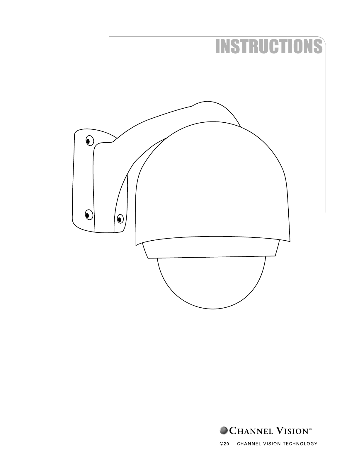
Outdoor PTZ Dome Camera with Fan & Heater
12
Page 2

Contents
I: Safety Warnings............................................................................................................................................
II: Introduction...................................................................................................................................................
Features......................................................................................................................................................
4
4
3
Box Contents.............................................................................................................................................
III: Installation, Wiring, Operation information
Measurements............................................................................................................................................
DIP Switch Settings; SW 1, SW 2...............................................................................................................
Assembly & Wiring of 6721.......................................................................................................................
Installation..................................................................................................................................................
OSD Configuration.....................................................................................................................................
Dome Information.......................................................................................................................................
Display Options..........................................................................................................................................
Camera Name Setup..................................................................................................................................
Zoom and Focus........................................................................................................................................
Control Options.........................................................................................................................................
5
6
7
8
9
10
10
11
11
11
12
Camera Exposure......................................................................................................................................
Others.........................................................................................................................................................
Preset Menu...............................................................................................................................................
Vectorscan.................................................................................................................................................
Pattern........................................................................................................................................................
Sector Setup..............................................................................................................................................
Motion.........................................................................................................................................................
Power On Action........................................................................................................................................
Limit Operation..........................................................................................................................................
Park Action.................................................................................................................................................
Special Camera Functions.................................................................................................................
Troubleshooting........................................................................................................................................
6721 Specifications...................................................................................................................................
13
14
15
16
16
17
18
18
18
19
20, 21
22
23
Warranty.....................................................................................................................................................
2
24
Page 3
Safety Warnings
IMPORTANT SAFETY INSTRUCTIONS
1. Read these instructions.
2. Keep these instructions for future reference.
3. Heed all warnings.
4. Follow all instructions.
5. Clean only with a dry cloth.
6. Install in accordance with these instructions.
7 Do not install near any heat sources such as radiators, heat registers, stoves, or other apparatus
that produce heat.
8. Do not defeat the safety purpose of the polarized-type plug. A polarized plug has two blades with
one wider than the other. The wide blade or the third prong are provided for your safety. If the
provided plug does not fit into your outlet, consult an electrician for replacement of the obsolete
outlet.
9. Protect the power cord from being walked on or pinched particularly at plugs, convenience
receptacles, and the point of exit from the apparatus.
10. Only use attachments/accessories specified by Channel Vision.
11. Unplug this apparatus during lightning storms or when unused for long periods of time.
12. Refer all servicing to qualified service personnel. Servicing is required when the apparatus has
been damaged in any way, such as power supply cord or plug is damaged, liquid has been
spilled or objects have fallen into the apparatus, the inside of the apparatus has been exposed to
rain or moisture, does not operate normally, or has been dropped.
13. The lightning flash with an arrowhead symbol within an equilateral triangle is intended to alert the
user to presence of uninsulated dangerous voltage within the product’s enclosure that may be of
sufficient magnitude to constitute a risk of electric shock to persons.
14. The exclamation point within an equilateral triangle is intended to alert the user to the presence
of important operating and maintenance accompanying the appliance.
15. Inside of apparatus shall not be exposed to dripping or splashing and objects filled with liquids.
CAUTION: To reduce the risk of electric shock,
do not remove the cover (or back). There are no
user-serviceable parts inside, refer servicing to
qualified service personnel.
CAUTION
RISK OF ELECTRIC SHOCK
RISK OF ELECTRIC SHOCK
DO NOT OPEN
DO NOT OPEN
!
3
Page 4

Introduction
Thank you for purchasing Channel Vision's 6721 Outdoor PTZ Camera. Please take the time to
read over these instructions to ensure proper installation and usage.
Channel Vision's hi-res 6721 Outdoor PTZ Camera provides pan, tilt and zoom functions
enabling wide area coverage and the ability to view objects in great detail with a 27x optical
zoom. This camera can be controlled with either a Channel Vision 3G Series Surveillance DVR
or from any device that supports Pelco D and Pelco P standards. With its high resolution 550 TV
line CCD, it is the perfect solution for any residential or commercial application that requires a
higher level of control than a standard analog camera.
Features
•
Supports up to 255 Camera Ids
•
Integrated multi-protocol and auto protocol differentiation
•
360 degree Pan (Up to 300 degrees per second)
•
90 degree Tilt (Up to 120 degrees per second)
•
2 degree angle adjustment, allowing viewing angle can be adjusted to 90 or 92 degrees
•
Supports 128 preset locations
•
IP66 rated for outdoor use
•
Long distance RS-485 transmission
•
4 Selectable baud rates
•
Camera name overlaid onto the video (location adjustable)
•
Supports up to 6 vector scans (preset tours with adjustable dwell time)
•
Supports privacy masking
Supports freeze frame functionality
•
•
Non-volatile memory
4
Page 5
Box Contents
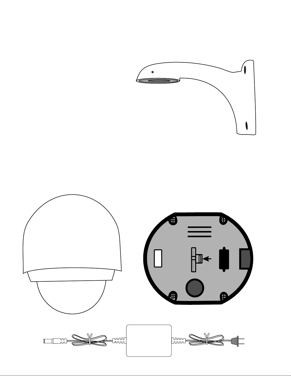
Items Included:
(1) Camera Mount
(1) Camera Enclosure
(1) Camera Module
(1) 24VAC Power Supply
(1) Instruction Manual
(4) Lag Screws
Tools & Accessories Required (Not included):
(1) Small screwdriver (flathead)
(1) Phillips Screwdriver
(1) Wire stripper
(1) Wire cutter
(1) Two conductor power wire (16 AWG)
(1) RG-59U coax cable
(2) BNC connectors
(1) Two conductor RS-485 wire (16-24 AWG)
(2) Crimp on splice connectors for power wires
(1) Allen key (size is 7/64)
6721 Camera Mount
6721 Camera Enclosure
6721 Camera Module (rear shown)
24VAC Power Supply
5
Page 6
12.60”
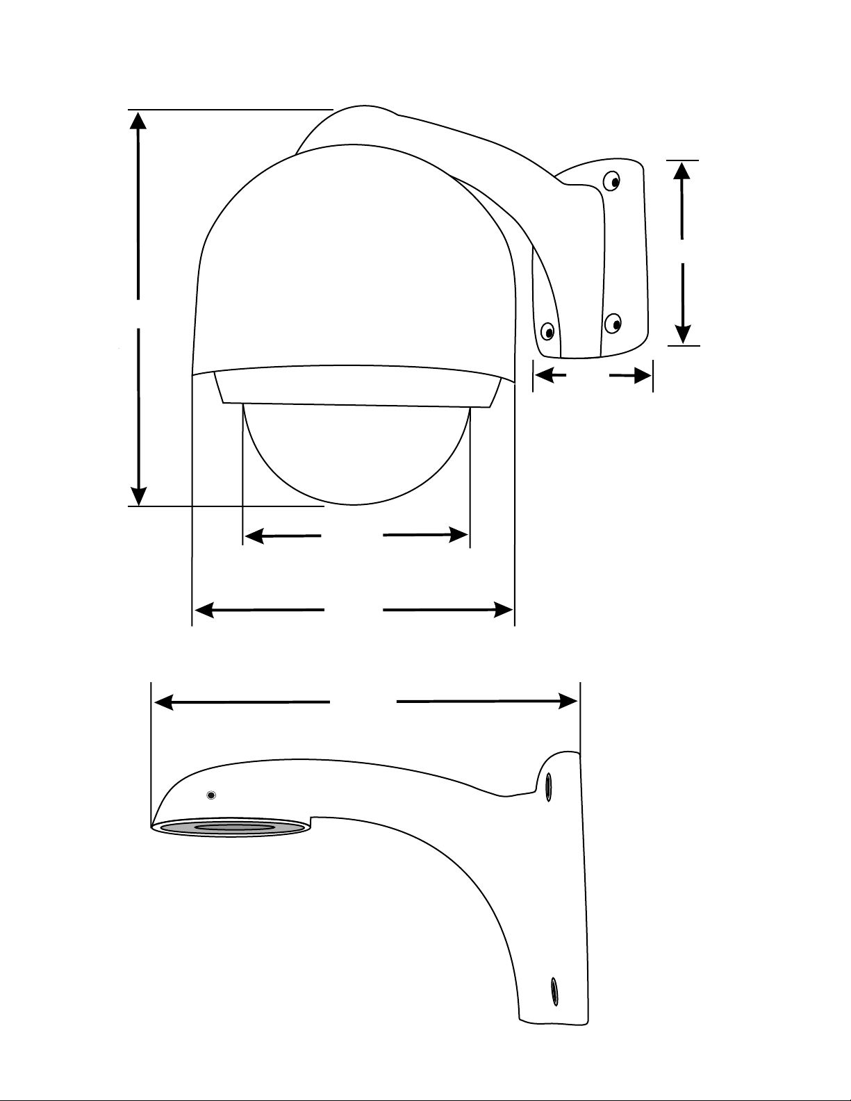
Measurements
6.89”
4.72”
6.14”
10.1”
10.96”
6
Page 7
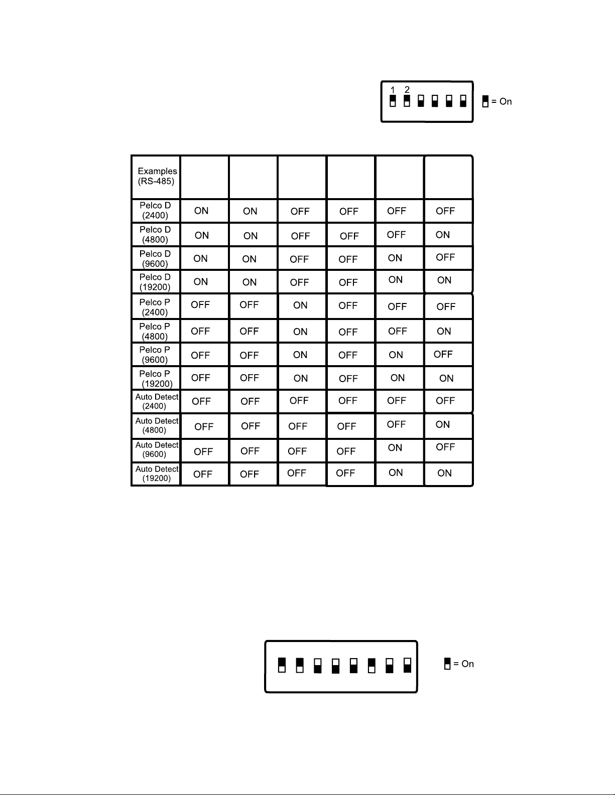
DIP Switch Settings
SW-1
Note:
These settings are also located on the bottom of the camera module.
The purpose of these switches are to designate protocol, baud rate,
and camera ID of each camera.
Pelco Standards (1, 2, 3 & 4)
1
2
3
SW-1
Example Set for Pelco D, 2400
ON
OFF
4
3
Baud Rate (5, 6)
5
5
6
4
6
DIP Switch Settings
SW-2
Note:
On SW-2, the sum of the DIP Switch values when they are in the ON position equals the address
of the dome device. Each dome in the system must have their own ID address.
For example, if DIP Switch 1, 2, and 6 are set to ON, the ID of the camera equals 35.
DIP Switch Values:
SW-2
DIP Switch 1 = 1
DIP Switch 2 = 2
DIP Switch 3 = 4
DIP Switch 4 = 8
DIP Switch 5 = 16
DIP Switch 6 = 32
DIP Switch 7 = 64
DIP Switch 8 = 128
(Example set to an ID of 35)
ON
OFF
2
1
3
4
5
6
8
7
7
Page 8
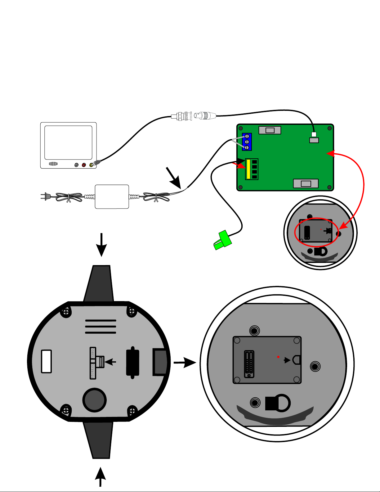
Assembly & Wiring of 6721
Important Note: Test camera prior to mounting
1.) Hook up power, video, and RS-485 connectors
2.) Tone wires to ensure proper communication
3.) Place camera module (A) into the 6721 camera assembly (B).
Make sure you secure the camera module (A) into camera assembly (B).
If properly secured, camera module (A) cannot be removed without pushing inwards in both tabs
Tabs are located on each side of the camera module (A).
Video
Camera
Power Supply
(cut end off power supply)
RF OUTRF OUT
AA
Monitor
Push both tabs (on either side)
inwards to remove camera (A)
from camera enclosure (B)
Make sure to unplug the
power supply before you cut wire
R
X
+
R
X
-
Open camera and
use tab to flip part
up to expose circuit
board
OPEN
)
A
(
ra
e
m
a
C
Tab
To PTZ controller (RS-485)
Connect to RX+ and RX-
on camera circuit board
When placing assembly A into assembly B,
be sure you hear a clicking sound, to ensure
the camera is locked into place
(B)
y
O
PE
N
m l
e b
Ass
a
r
e
m
a
C
Tab
8
Page 9

Installation
Note: The installation of the 6721 camera is shown below.
BNC connector
Sea
l ith i
w sil con
Camera
Wires
Wall Mount
Allen Key
(size is 7/64)
1. Drill a hole for wiring to exit the
wall
2. Feed camera wires through the
base of the wall mount
3. Attach mount to wall with
screws
4. Connect camera pigtail to the
base of the camera
5. Feed wires through camera
enclosure
6. Screw camera enclosure onto
wall mount
i
o V deT
pl y
i
D s a
o
eWire Ext nsions
not included)
(
Controller
Crimp-on splice
connectors
(not included)
To PTZ
6721 Camera
7. Secure the camera to the
mount using the set screw
(allen key size is 7/64)
8. Connect the camera wires to
wire extensions or directly to a
video display system
9. Connect the BNC video output
to a monitor or distribution
system
10. Connect RS-485 wires to
PTZ controller such as a
DVR or Web Server
11. Apply silicon sealant between
camera mount and wall, side of
cable entrance to mount, and
on the screws to help prevent
exposing camera to moisture
12. Plug power supply into wall
Power Supply
9
Page 10
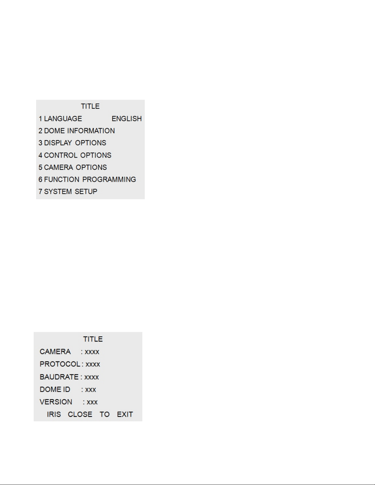
OSD (On Screen Display) Configuration
Menu Operation Instructions
To make a selection, enter preset 95 (on a Channel Vision DVR) or move the joystick on your
PTZ controller in the Up or Down direction. The on-screen arrow points to the selected option.
Using the joystick to the Left or Right position you can change the value of your selection or
enter the submenu for the selected option. Press the escape button on the keyboard
controller to exit the menu or return to the previous menu (one layer up).
Title Menu
1. Language Setup
Used to change operation language of the camera
2. Dome Information
Displays general dome information of the camera
3. Display Options
Used to control display options of the camera
4. Control Options
Used to set the pan or tilt of the camera manually
or automatically in the camera
5. Camera Options
Used to set camera functions
6. Function Programming
Program and execute PTZ and Vectorscan etc
7. System Setup
Used to configure general system setup, including,
restoring default setup, clearing the memory,
changing color system, and resetting the camera
Dome Information
Dome Information Menu
1. Camera
Displays the camera name
2. Protocol
Displays the protocol of the camera
3. Baudrate
Displays the baud rate of the camera
10
4. Dome ID
Displays the dome ID (1-255)
5. Version
Displays the software version
Page 11
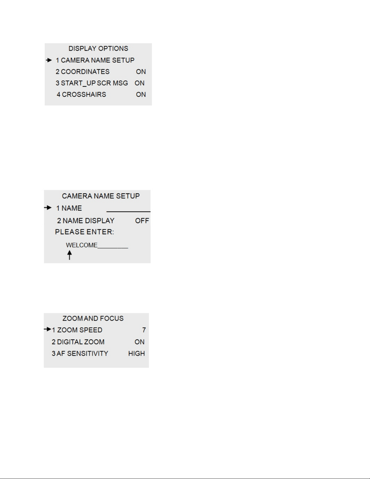
Display Options
Display Options Menu
1. Camera Name Setup
Used to change camera name
2. Coordinates
Used to turn off/on coordinates on the displayed image
3. Start_Up Scr Msg
Used to turn off/on start up messages
4. Crosshairs
Used to turn the crosshairs off/on
Camera Name Setup
Dome Information Menu
1. Name
Used to set camera name
2. Name Display
Displays the protocol of the camera
Zoom and Focus
Zoom and Focus
1. Zoom Speed
Used to change the zoom speed
2. Digital Zoom
Used to turn digital zoom off/on
3. AF Sensitivity
Used to adjust auto focus sensitivity
11
Page 12
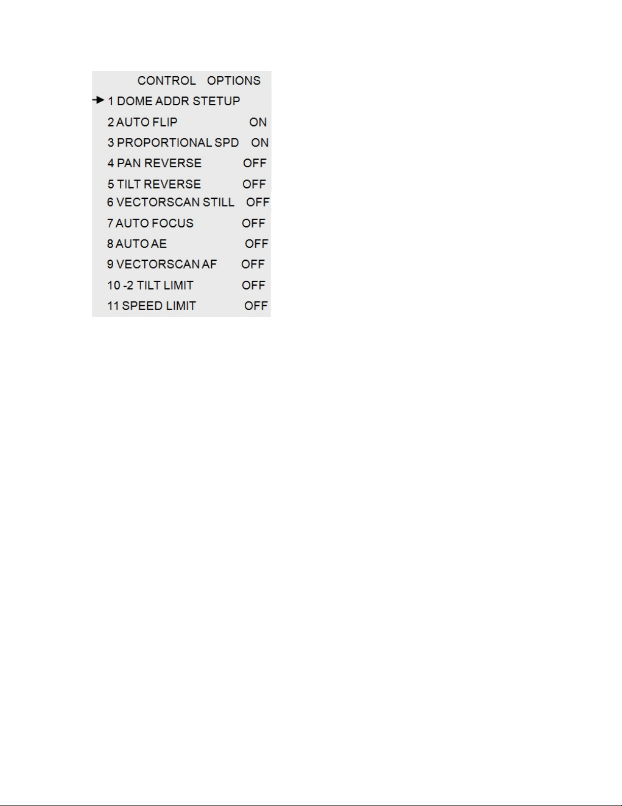
Control Options
Control Options
1. Dome Address Setup
Used to set dome address
2. Auto Flip
Used to turn auto-flip off/on
3. Proportional SPD
Used to turn proportional speed off/on
4. Pan Reverse
Used to turn pan reverse off/on
5. Tilt Reverse
Used to turn tilt reverse off/on
6. Vectorscan Still
Used to turn still vectorscan off/on
7. Auto Focus
Used to turn auto-focus off/on
8. Auto AE
Used to turn auto-ae off/on
9. Vectorscan AF
Used to turn vectorscan auto focus off/on
10. 2 Tilt Limit
Used to turn 2 tilt limit off/on
11. Speed Limit
Used to turn speed limit off/on
12
Page 13
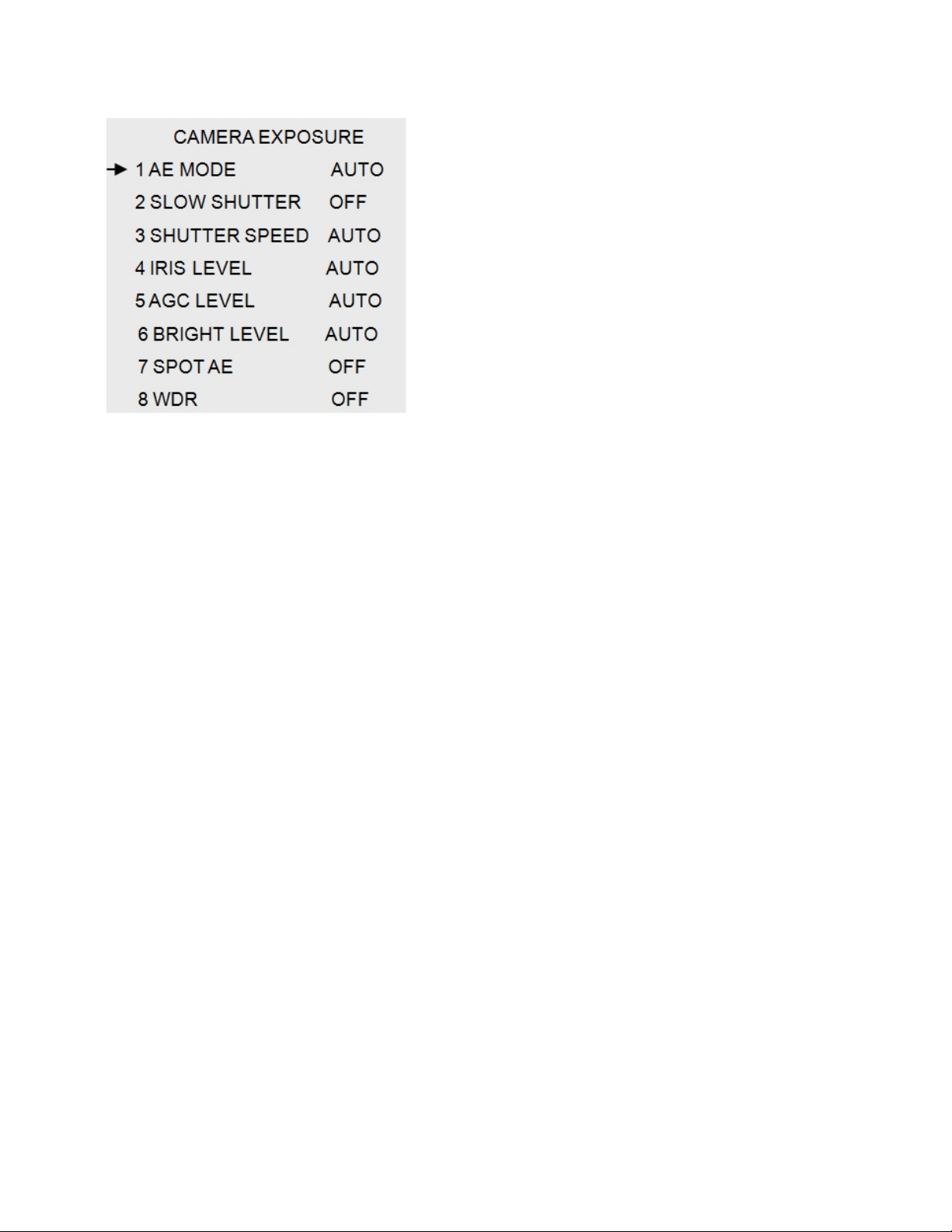
Camera Exposure
Camera Exposure
1. AE Mode
Used to control the AE mode of the camera
2. Slow Shutter
Used to turn off/on slow shutter speed of the camera
3. Shutter Speed
Used to set general shutter speed of the camera
4. Iris Level
Used to control the iris level of the camera
5. AGC Level
Used to set the AGC level of the camera
6. Bright Level
Used to adjust the brightness of the camera
7. Spot AE
Used to turn Spot AE off/on in the camera
8. WDR
Used to turn WDR (Wide Dynamic Rang) off/on in the
camera
13
Page 14
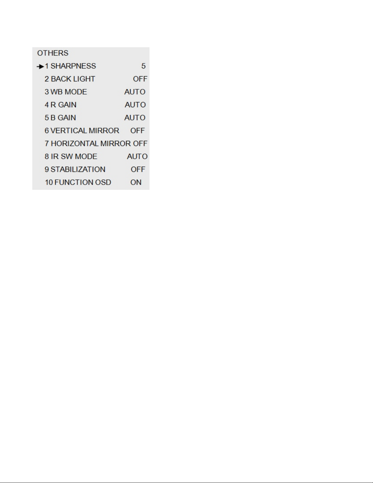
Others
Others
1. Sharpness
Used to adjust sharpness of the camera
2. Back Light
Used to turn back light off/on in the camera
3. WB Mode
Used to adjust WB mode in the camera
4. R Gain
Used to adjust R Gain in the camera
5. B Gain
Used to adjust B Gain in the camera
6. Vertical Mirror
Used to turn Vertical Mirror off/on in the camera
7. Horizontal Mirror
Used to turn Horizontal Mirror off/on in the camera
8. IR SW Mode
Used to adjust IR SW mode in the camera
9. Stabilization
Used to turn image stabilization off/on in the camera
10. Function OSD
Used to turn function OSD (on screen display)off/on
in the camera
14
Page 15
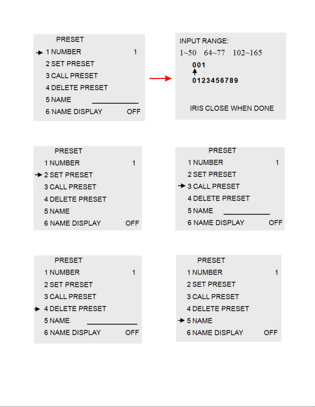
1. Number
Used to adjust the preset number
Preset Menu
2. Set Preset
Used to set the preset
4. Delete Preset
Used to delete the preset
3. Call Preset
Used to call the preset
5. Name
Used to delete the preset
6. Name Display
Used to turn name display off/on
15
Page 16
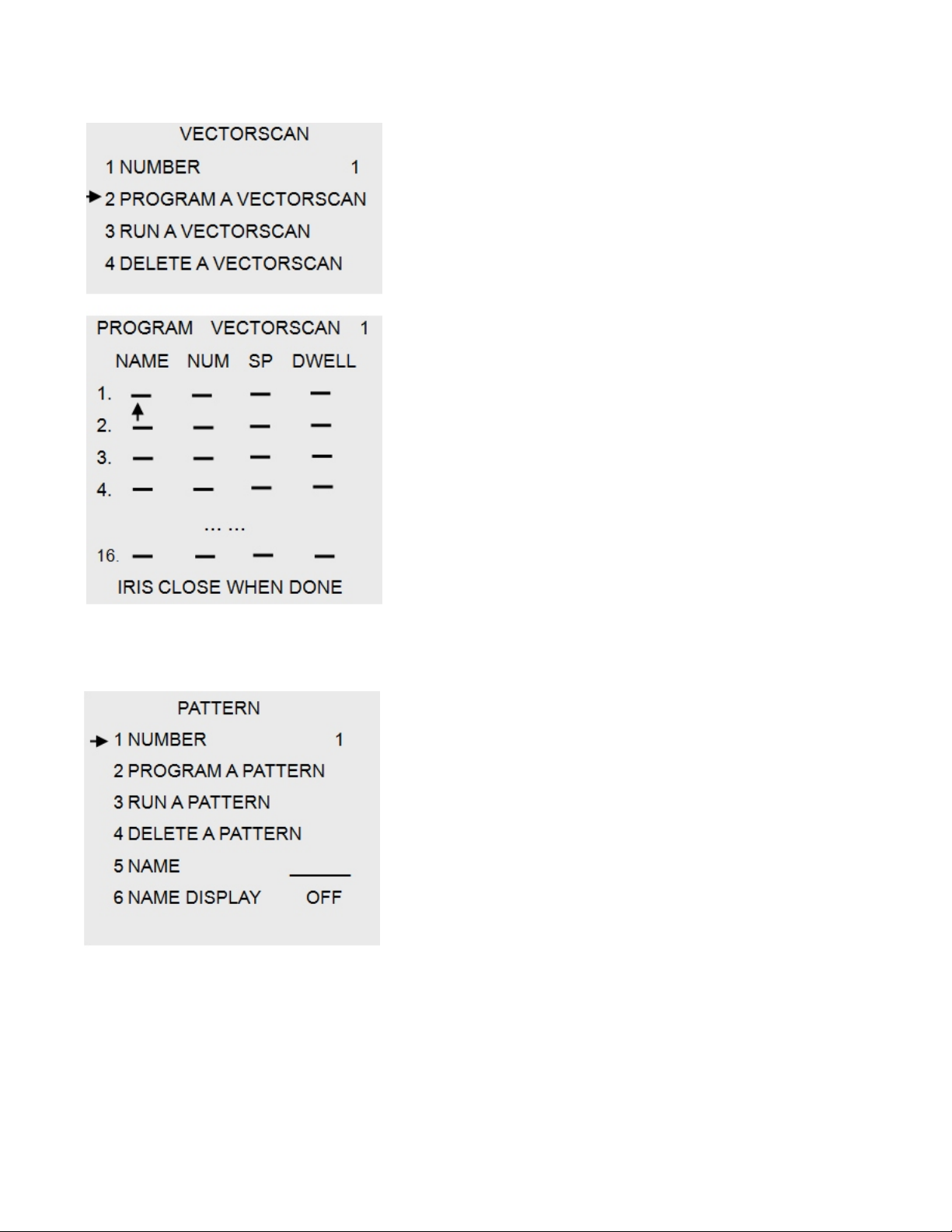
Vectorscan
Vectorscan
1. Number
Used to set the number of the Vectorscan
2. Program a Vectorscan
Used to program each Vectorscan. Each scan has a name,
number, (NUM) speed, (SP) and dwell time.
3. Run a Vectorscan
Used to run a specific Vectorscan
4. Delete a Vectorscan
Used to delete a Vectorscan
Pattern
Pattern
1. Number
Used to set the number of a pattern
2. Program a Pattern
Used to program each pattern
3. Run a Pattern
Used to run a specific pattern
4. Delete a Pattern
Used to delete a pattern
5. Name
Used to name a pattern
6. Name Display
Used to turn name display off/on
16
Page 17
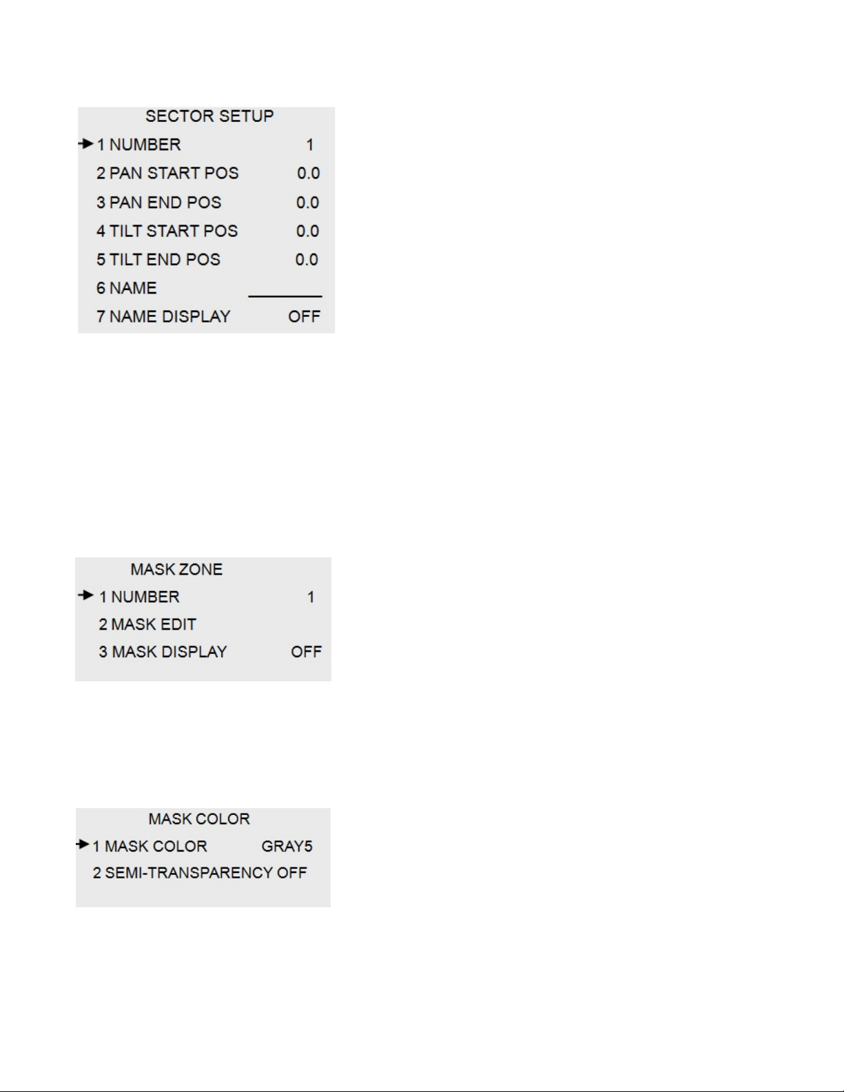
Sector Setup
Sector Setup
1. Number
Used to set the number of the Sector Setup
2. Pan Start POS
Used to designate the starting position of the pan
3. Pan End POS
Used to designate the ending position of the pan
4. Tilt Start POS
Used to designate the starting position of the tilt
5. Tilt End POS
Used to designate the ending position of the tilt
6. Name
Used to name the Sector Setup you are creating
7. Name Display
Used to turn off/on name display
Mask Zone
1. Number
Used to set the number of Mask Zone
2. Mask Edit
Used to edit the masking area
3. Mask Display
Used to turn Mask Display off/on
Mask Color
1. Mask Color
Used to set the color of the masked area
2. Semi-Transparency
Used to turn off/on semi transparency on masking
17
Page 18
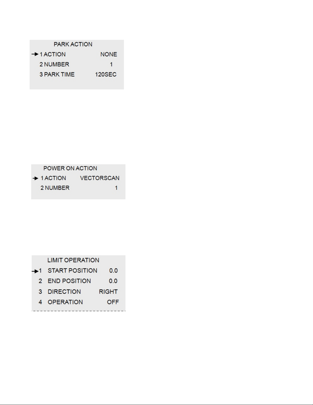
Motion
Park Action
1. Action
Used to specify park action
(None/Preset/VectorScan/Pattern/PanScan/AutoScan)
2. Number
Used to set park action number
3. Park Time
Used to designate the amount of time for each park
Power On Action
Power On Action
1. Action
Used to specify power on action
(None/Preset/VectorScan/Pattern/PanScan/AutoScan)
2. Number
Used to set action number
Limit Operation
Limit Operation
1. Start Position
Used to specify camera starting position
2. End Position
Used to specify camera ending position
3. Direction
Defines the direction of the camera boot up sequence
18
4. Operation
Enables or disables boot up test sequence
Page 19
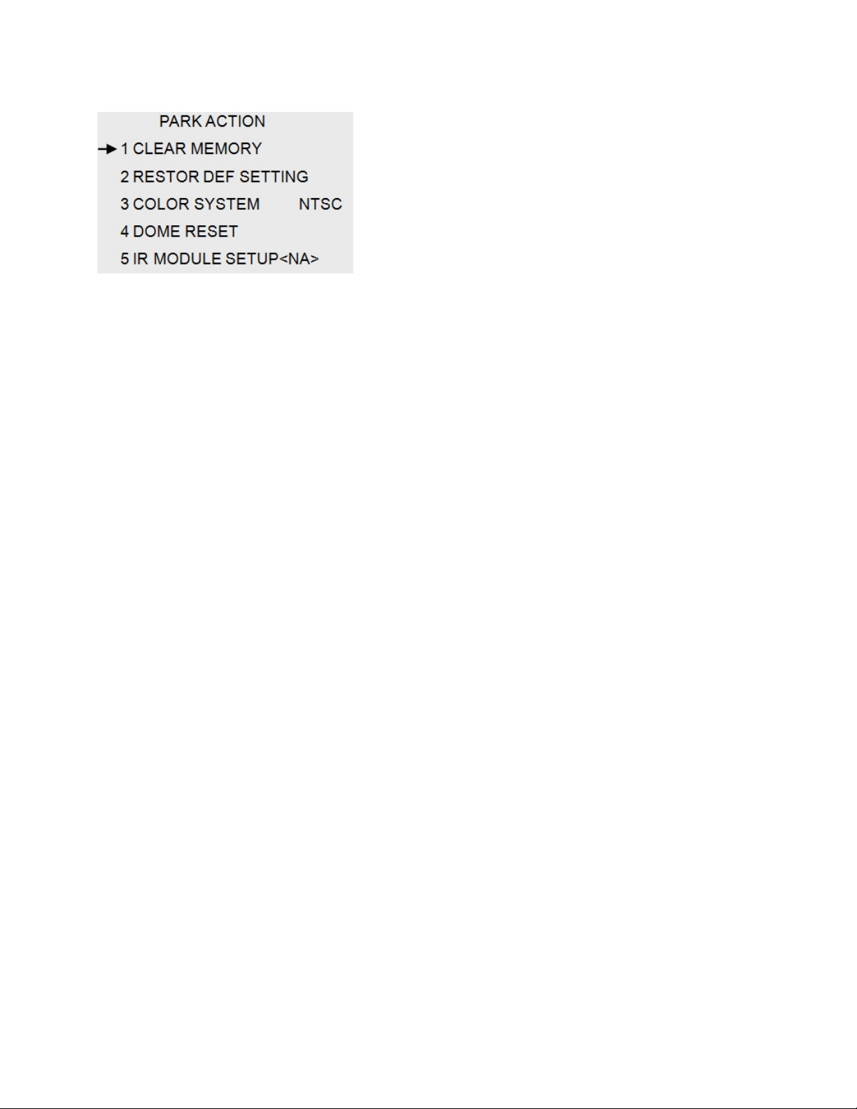
Park Action
Park Action
1. Clear Memory
Used to clear the memory of the camera
2. Restor Def Setting
Used to restore camera to factory default settings
3. Color System
Defines the color system used in the camera
Default is NTSC.
4. Dome Reset
Allows you to reset the dome
5. IR Module Setup <NA>
Not available in this camera
19
Page 20
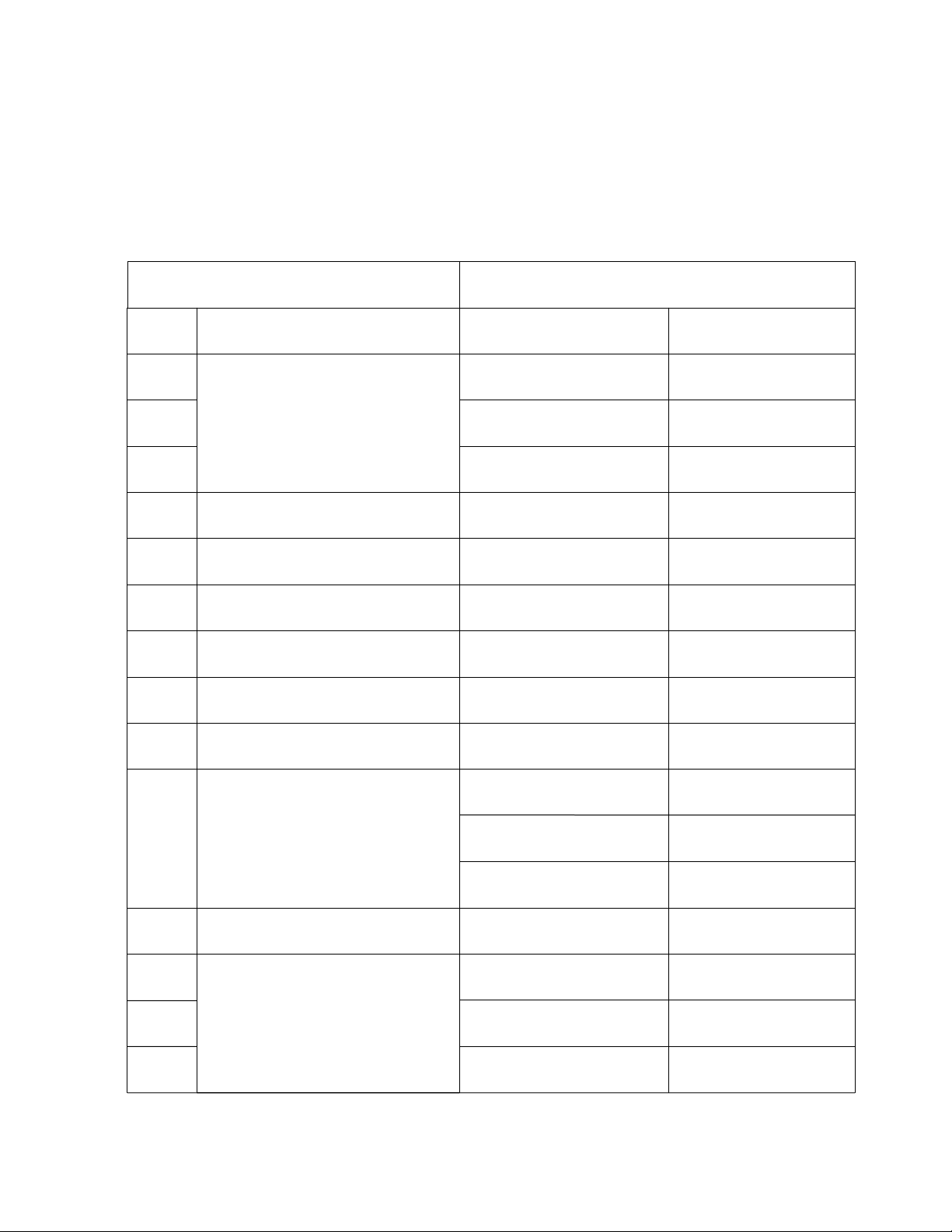
Special Camera Functions
The special functions listed below are only available when the 6721 is used with a Pelco
standard PTZ controller.
Note: Not all PTZ controllers will support these commands.
Keyboard Button Sequence
No.
51
52
53
55
56
57
58
59
60
Control Function
Pan-Tilt
Compensation
Control
Camera Power Control
Background Light
Compensation*
Camera Related OSD
Digital Zoom
Focus
Iris
[CALL] + No. [PRESET] + No.
Record line-scanning
Start line-scanning
Power On
On
Camera Menu
on/off
On
Auto
Auto
Run Cruise Track
Set starting point
for scanning
Set ending point
for scanning
Power Off
Off
Camera Function
OSD on/off
Off
Manual
Manual
20
61
62
63
79
80
81
82
White
Balance
Mode*
Set Line Scanning Mode
Run Pattern
Auto
Indoor
ATW
Long Distance
Run Pattern One
Run Pattern Two
Run Pattern Three
Manual
Outdoor
One Push WB
Short Distance
Page 21
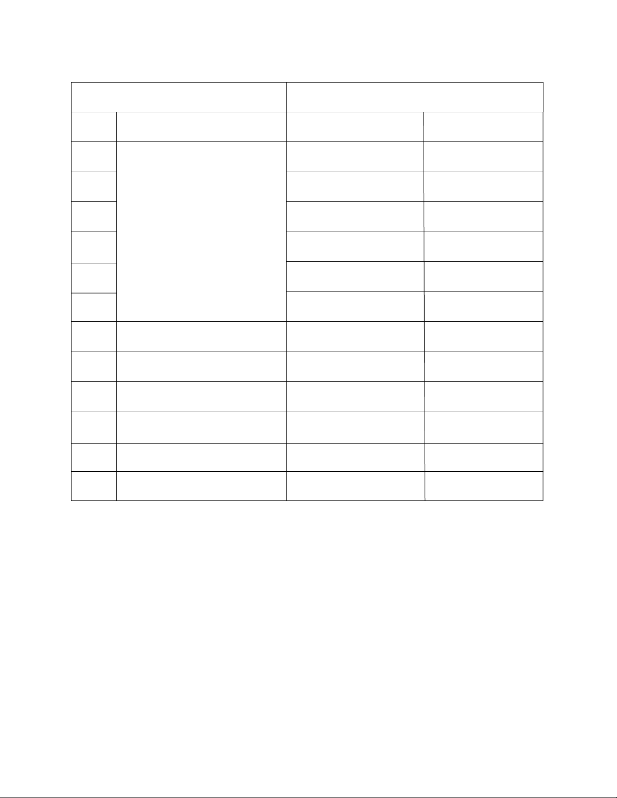
Special Camera Functions, cont.
Keyboard Button Sequence
No.
83
84
85
86
87
88
89
91
94
Control Function
Record Vectorscan
Freeze Image
Dynamic Preset Point
Dome Reset
[CALL] + No. [PRESET] + No.
Run Vectorscan One
Run Vectorscan Two
Run Vectorscan Three
Run Vectorscan Four
Run Vectorscan Five
Run Vectorscan Six
On
Call Dynamic
Preset Point
Reset Dome
Off
95
96
101
Main Menu
Set Auto Flip
Continuous Pan
Call Main Menu
On
On
Off
21
Page 22

Troubleshooting
Problem
No motion and no video
Normal Video output, but
abnormal motion
Have motion control, but no
video
Possible Cause
Power supply is disconnected
or damaged
Power supply voltage is too low
Faulty coax connection
Solution
Check power supply.
Replace if needed
Make sure to use the
correct power supply
Move the power supply
closer to the camera
Check with cable tester
or verify cable by
sending known good
video signal through it
Normal video output, but no
motion control
Camera protocol does not
match controller
Check the DIP
Switches
22
Page 23

6721 Specifications
Operating Voltage: 24VAC 3000mA
Power Consumption: 2.8 Watts (no heater or fan) 5.1 Watts maximum
CCD Size: 1/4” Super HAD color CCD
Total Pixels: 811 (H) x 508 (V)
Effective Pixels: 768 (H) x 494 (V)
Optics: 27X, F=3.5 to 94.5mm (F 1.6 to 2.9)
Digital Zoom: Off/On (Maximum 12x)
Field of View: (H) 55.5 Degrees (Wide) to 2.24 Degrees (Tele)
(V) 42.5 Degrees (Wide) to 1.79 Degrees (Tele)
Scanning System: 2:1 Interlace
Synchronization: Internal
Frequency: H: 15.734 Khz / V: 59.94 Hz
Resolution: 550 TV Lines (Color)
Min. Illumination: 0.4 Lux/F1.6 (50IRE) Color
S/N Ratio: (Y signal) 50dB
Video Output: CVBS: 1.0Vp-p / 75 Ohms
Focus: Auto/Manual / One Push
Zoom Speed: 1.8 seconds (fast) 2.3 seconds (middle) 4.5 seconds (slow)
Iris Control: Auto/Manual
Lens Initialize: Built-In
Camera Title: On/Off
Camera ID: 255 Possible I
Day & Night: Auto / Color/ B/W
Gain Control: Low / Medium / High / Manual / Off
White Balance: ATW / AWC / Manual / Indoor / Outdoor
Backlight: BLC / HLC / OFF
Electronic Shutter: Auto / Manual / A.FLK
O.S.D. : Built in
Motion Detection: Yes; On / Off (output via communication)
Control Output: RS-232C TTL Level (2400, 4800, 9600, 19200, 38400, 57600, 115200 bps
SSNR: Low / Medium / High / Off
Privacy Function: On / Off (8 selectable areas)
Flip: On / Off
Mirror: On / Off
Dis: On / Off
Preset: 128 Possible presets
Operating temperature: -40 C to 50 C
Case Rating: P66
I
Ds
*Specifications subject to change without notice.
23
Page 24
1
Channel Vision Technology will repair or replace any defect in material or
workmanship which occurs during normal use of this product with new or rebuilt
parts, free of charge in the USA, for one year from the date of original purchase. This
is a no hassle warranty with no mail in warranty card needed. This warranty does not
cover damages in shipment, failures caused by other products not supplied by
Channel Vision Technology, or failures due to accident, misuse, abuse, or alteration
of the equipment. This warranty is extended only to the original purchaser when
purchased through an authorized reseller. A purchase receipt, invoice, or other
proof of original purchase date will be required before warranty repairs are provided.
Mail in service can be obtained during the warranty period by calling (800) 840-0288
toll free. A Return Authorization number must be obtained in advance and can be
marked on the outside of the shipping carton.
This warranty gives you specific legal rights and you may have other rights (which
vary from state to state). If a problem with this product develops during or after the
warranty period, please contact Channel Vision Technology, your dealer or any
factory-authorized service center.
Channel Vision products are not intended for use in medical, lifesaving, life
sustaining or critical environment applications. Channel Vision customers using or
selling Channel Vision products for use in such applications do so at their own risk
and agree to fully indemnify Channel Vision for any damages resulting from such
improper use or sale.
Tested To Comply
With FCC Standards
This device complies with part 15 of the FCC rules. Operation is subject to the following two
conditions: (1) This device may not cause harmful interference, and (2) This device must accept any
interference received, including interference that may cause undesired operation.
w w w . c h a n n e l v i s i o n . c o m
234 Fischer Avenue, Costa Mesa, California 92626 USA
(714)424-6500 (800)840-0288 (714)424-6510 fax
email: [email protected]
500-307 rev G
 Loading...