

Page 1
6535
1080P 2 Megapixel Mini Dome IP Camera w/POE
IR LEDs & Two Way Audio
• Intelligent Entertainment • Infrastructure • Security Solutions
Page 2

Table Of Contents
2
Introduction ................................................................................ Page 3
Safety Warnings.......................................................................... Page 4
Cable Pin Out.............................................................................. Page 5
Camera Assembly....................................................................... Page 6
IP Setup....................................................................................... Page 7-13
Configuring Internet Explorer....................................................... Page 14 Live
Viewing........................................................................................ Page 15-16
Configuration............................................................................... Page 17
System Configuration.................................................................. Page 18
User Management....................................................................... Page 19
System Update............................................................................ Page 20
Network....................................................................................... Page 21-25
ONVIF ........................................................................................ Page 26
Video Settings............................................................................. Page 27-33
Event List.................................................................................... Page 34-35
Schedule..................................................................................... Page 36
Port Forwarding......................................................................... Page 37
UPNP Port Forwarding............................................................... Page 38
Factory Reset............................................................................. Page 39
Specifications............................................................................. Page 40
Warranty...................................................................................... Page 41
Page 3
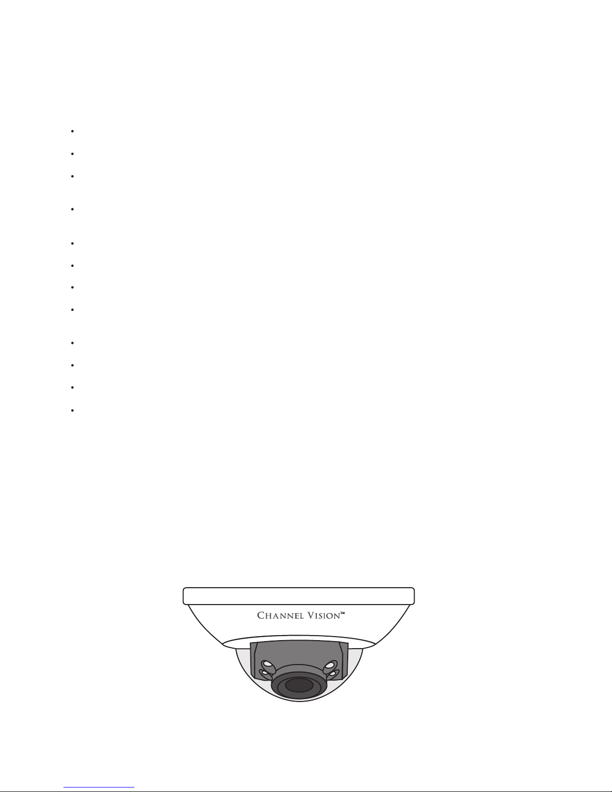
The 65 is a
Built-in web server allows a user to view high quality, real-time video with Internet Explorer browser.
Multi-Stream H.264, MJPEG and MPEG
Live video can be recorded to an NVR and played back remotely, as well as viewed from many mobile
phones and other devices.
Designed for large commercial projects with 100’s of cameras or a single family house requiring a camera at
the front door.
Android, iPhone & iPad app available from the respective store
2.8mm fixed focal length lens
36 Camera CMS (Central Management software, included) will allow you to see all of your cameras
anywhere in the world in multiple locations at the same time
High definition 1080P at 30FPS
Digital Wide Dynamic Range
Power Over Ethernet or 12vDC power supply
Two Way Audio
Micro SD card recording slot inside camera
6535 Features:
Channel Vision’s 6535 IP mini dome camera offers superior image quality with a 2 megapixel CMOS sensor
and has the ability to capture images up to 1920 x 1080 pixels.
With H.264 compression, less bandwidth and storage space are used, while delivering full resolution at max
frame rate with faster speeds over the internet. Monitoring can be done anywhere an internet connection is
available even from a Smart-phone. The 6535 also features event triggered motion recording.
35 1080p 2 Megapixel Mini Dome IP Camera w/POE, IR and Two Way Audio.
Model 6535
6535
3
Page 4
Safety Warnings
IMPORTANT SAFETY INSTRUCTIONS
1. Read these instructions.
2. Keep these instructions for future reference.
3. Heed all warnings.
4. Follow all instructions.
5. Clean only with a dry cloth.
6. Install in accordance with these instructions.
7 Do not install near any heat sources such as radiators, heat registers, stoves, or other apparatus
that produce heat.
8. Do not defeat the safety purpose of the polarized-type plug. A polarized plug has two blades with
one wider than the other. The wide blade or the third prong are provided for your safety. If the
provided plug does not fit into your outlet, consult an electrician for replacement of the obsolete
outlet.
9. Protect the power cord from being walked on or pinched particularly at plugs, convenience
receptacles, and the point of exit from the apparatus.
10. Only use attachments/accessories specified by Channel Vision.
11. Unplug this apparatus during lightning storms or when unused for long periods of time.
12. Refer all servicing to qualified service personnel. Servicing is required when the apparatus has
been damaged in any way, such as power supply cord or plug is damaged, liquid has been
spilled or objects have fallen into the apparatus, the inside of the apparatus has been exposed to
rain or moisture, does not operate normally, or has been dropped.
13. The lightning flash with an arrowhead symbol within an equilateral triangle is intended to alert the
user to presence of uninsulated dangerous voltage within the product’s enclosure that may be of
sufficient magnitude to constitute a risk of electric shock to persons.
14. The exclamation point within an equilateral triangle is intended to alert the user to the presence
of important operating and maintenance accompanying the appliance.
15. Inside of apparatus shall not be exposed to dripping or splashing and objects filled with liquids.
CAUTION: To reduce the risk of electric shock,
do not remove the cover (or back). There are no
user-serviceable parts inside, refer servicing to
qualified service personnel.
CAUTION
RISK OF ELECTRIC SHOCK
DO NOT OPEN
!
4
Page 5
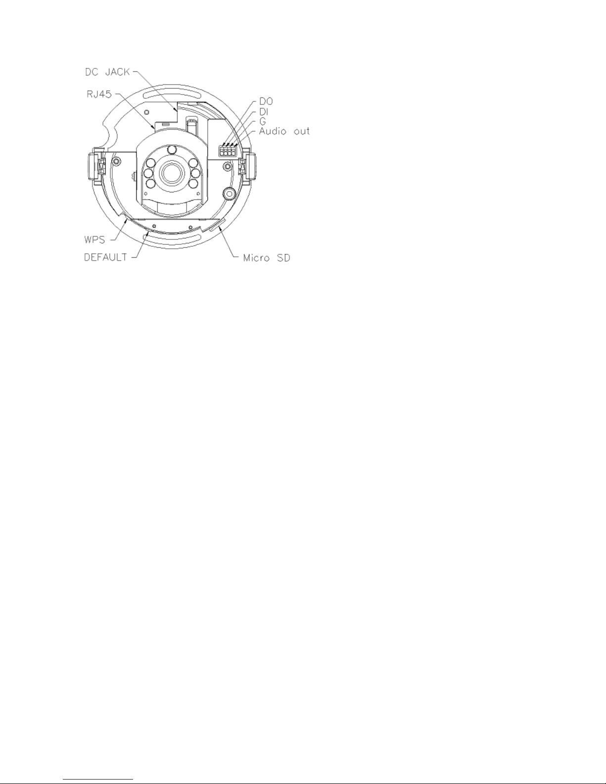
The breakout cable on Channel Vision’s IP Cameras are used for motion detection, event triggering,
alarm notifications etc.
The provided interface connections are explained below.
1. Audio Output ( Audio Out + Ground)
An audio output that can be fed into an amplifier
2. Audio Input
A microphone is built into this IP camera
3. Reset to factory default
To restore your IP camera to Channel Vision default settings, unplug the power supply from the
camera. Then, plug in power cable and press the “reset” button on the camera for 30 seconds. Once
30 seconds have passed, remove the electric wire and plug in the Ethernet cable. Use IP installer to
find the camera IP. (Default is http://192.168.1.200) Default username and password is “admin”
Cable Pin Out
PoE (Power Over Ethernet)
5
Power over Ethernet (PoE) is a technology that integrates power into a standard LAN infrastructure. It
enables power to be provided to the network device, such as an IP phone or a network camera, using
the same cable that is used for the network connection.
The PoE switch eliminates the need for power outlets at the camera locations and enables an easier
application of uninterruptible power supplies (UPS) to ensure 24 hours a day, 7 days a week operation.
The recommended requirement for a PoE switch is 802.3at, 30.0W.
The minimum requirement for a PoE switch is 802.3af 15W.
If using a PoE switch that does not meet these specifications, full functionality may not be supported.
WARNING: DO NOT CUT THE BREAKOUT CABLE.
CUTTING THE CABLE WILL VOID THE WARRANTY ON THE DEVICE.
To access the micro
SD card slot and
reset button, remove
the camera cover.
Page 6
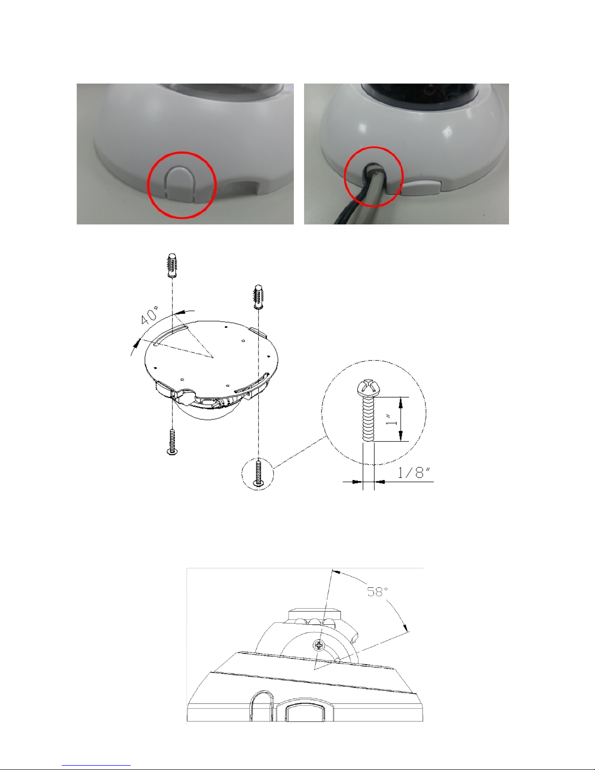
Camera Assembly
6
Pop out the plastic tab to run your wires through the hole.
Use screws to mount the bottom of camera to the ceiling or the wall. After adjusting the lens, tighten the
screws.
Page 7
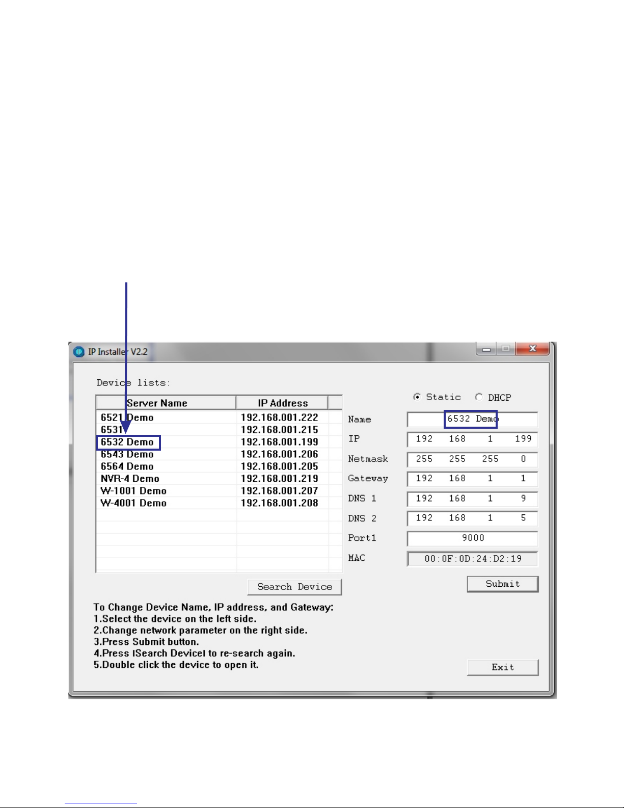
Your IP Camera comes set to DHCP by default. This means that, just like your laptop computer or desktop PC, an IP
address is automatically assigned to the IP camera by your router. This, combined with UPnP (Universal Plug and
Play), will make the IP setup of the IP camera a quick and easy task to accomplish.
*For the best security, Channel Vision recommends you use a static IP setting and standard port forwarding.
1. Open IP installer. This is located on your software disk.
2. An IP address should already be assigned
In the example below, the router has assigned 192.168.1.199 to the IP Camera
3. Double click on the name of the IP Camera. This will open the IP camera in your default browser
Option One: Assigning an IP Address (DHCP)
7
Page 8
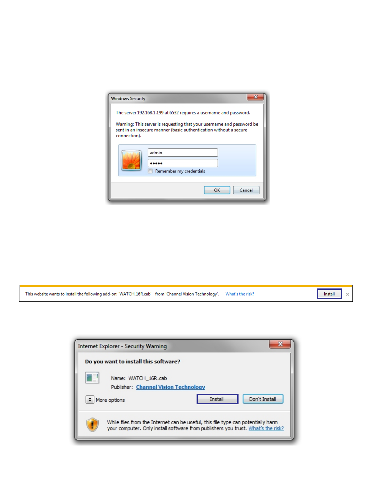
Connecting To The IP Camera (DHCP)
5. The first time you connect to the camera via Internet Explorer, it will ask you to install the ActiveX control.
Internet Explorer 6, 7, 8, or 9 must be used to run this ActiveX control.
4. You will be prompted for a username and password.
The default username is ‘admin’
The default password is ‘admin’
Installing The ActiveX Control
8
Page 9
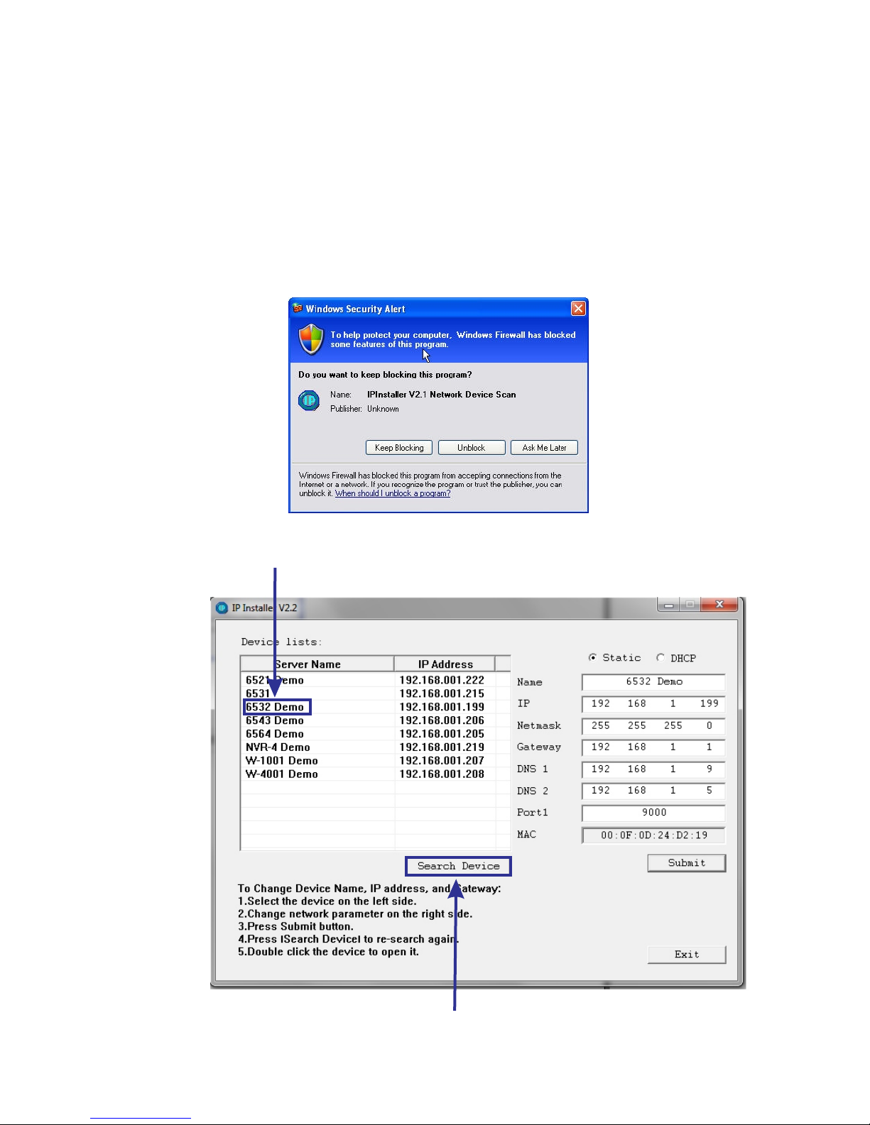
1. Use the software, “IP Installer” to assign the IP address to your IP Camera.
You can find "IP Installer" in the supplied CD.
2. Execute IP Installer, located on your disk under the folder “Software”
3. If Windows prompts you to unblock IP Installer, you must select “unblock”
There are 3 options of IP configuration:
A. Fixed IP (Public IP or Virtual IP)
B. DHCP (Dynamic IP)
C. Dial-up/DSL (PPPoE)
"IP Installer" will search all IP Cameras connected to your LAN network.The user can
click “Search Device” to search again.
Double click the camera name to go directly to the camera
Option Two: Assigning an IP Address (Static)
9
Page 10
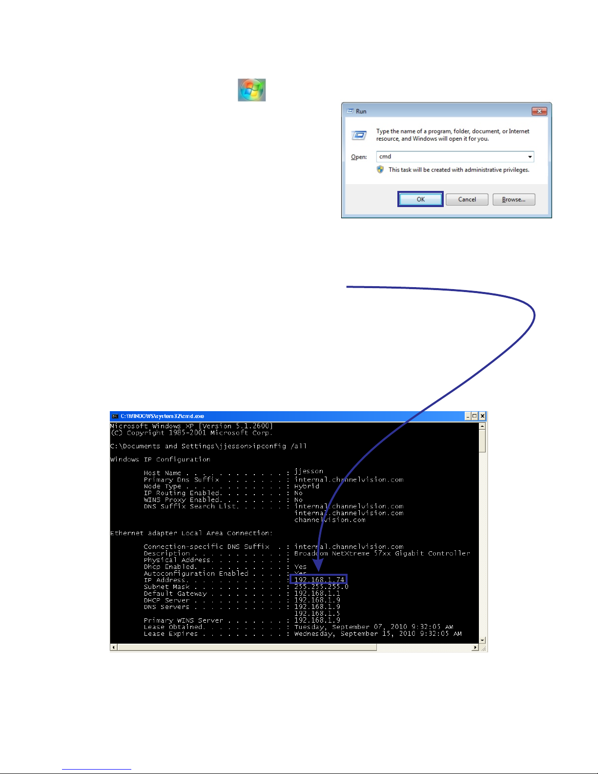
Assigning an IP Address (Static) /cont
4. Click the start icon on your computer.
5. Type the word “run” and select enter on your keyboard.
6. Type in ‘cmd’ and press enter on your keyboard, or press ok.
7. Type in ‘ipconfig /all’ into the DOS prompt that appears. Press “Enter”.
8. Write down your computer’s IP address.
Do not use the same IP address as the computer in the IP Camera.
In the example below, the computer’s IP address is 192.168.1.74.
The IP address of the IP camera must be different than the IP address in the computer.
Each network-able device in your network has an IP address assigned.
The IP chosen for your IP Camera is not the same address as any other device on your network.
10
Page 11
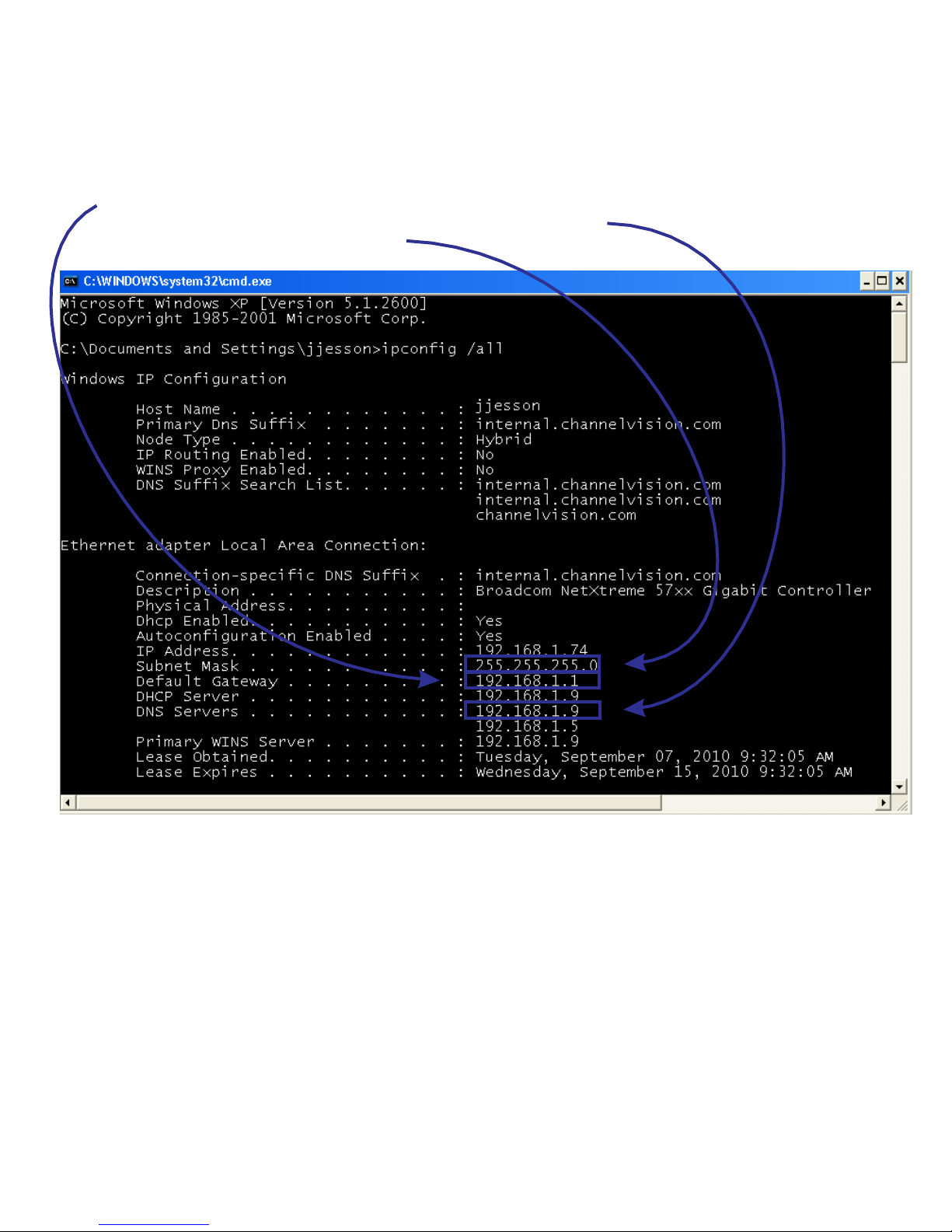
9. Copy/write down the following information from the DOS prompt.
A. Default Gateway (Example 192.168.1.1)
B. DNS Server (if 2 servers, use the first one, for example 192.168.1.9)
C. Subnet Mask (Example 255.255.255.0)
11
Assigning an IP Address (Static) /cont
Page 12
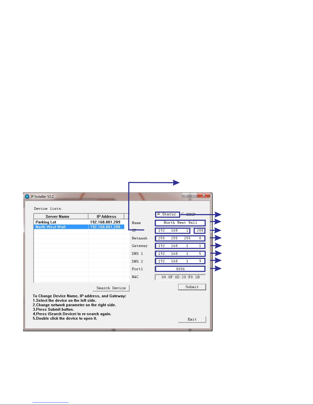
To change numbers, select the appropriate area on IP installer
with your mouse, and type in the info.
7. Enter the information you wrote down into the IP camera network page
A. Default Gateway (Enter this number under “Gateway”)
B. DNS Server (Enter this number under “DNS 1”)
C. Subnet Mask (Enter this number under “Netmask”)
8. Giving the IP Camera a unique IP address.
Assign an IP address to the IP Camera by using the first 3 sets of numbers of your default gateway.
An IP address has 4 sets of numbers, each followed by a period.
For example, xxx.xxx.xxx.xxx
My default gateway is 192.168.1.1
For example, my IP Camera’s address will start with 192.168.1.xxx
9. Make sure you use a number different that your computer’s IP address.
(Generally between 2-250) This number needs to be out of the range of DHCP. DHCP is assigned with
your router, and can be checked by logging into the router.
My computer’s IP address is 192.168.1.74. 192.168.1.208 is used in the example below.
You must choose a number that is different from your computer’s IP.
If your IT technician has designated a static internal IP for your IP Camera, use that address.
10. To assign the port, choose a port between 5400-9000, and type it into “Port 1” If a specific port has
*Disclaimer: This is an example based on a general network setup.
All networks do not match these settings exactly, as all networks are different
Name
Fourth number (different than computer)
Select “Static”
Subnet Mask (same as computer)
Default Gateway (same as computer)
DNS Server 1 (same as computer)
DNS Server 2 (same as computer)
Port (A port between 9000-9999 is
recommended, but any network
port can be used)
First 3 sets of numbers
are same as the computer’s IP address
12
Assigning an IP Address (Static) /cont
Page 13
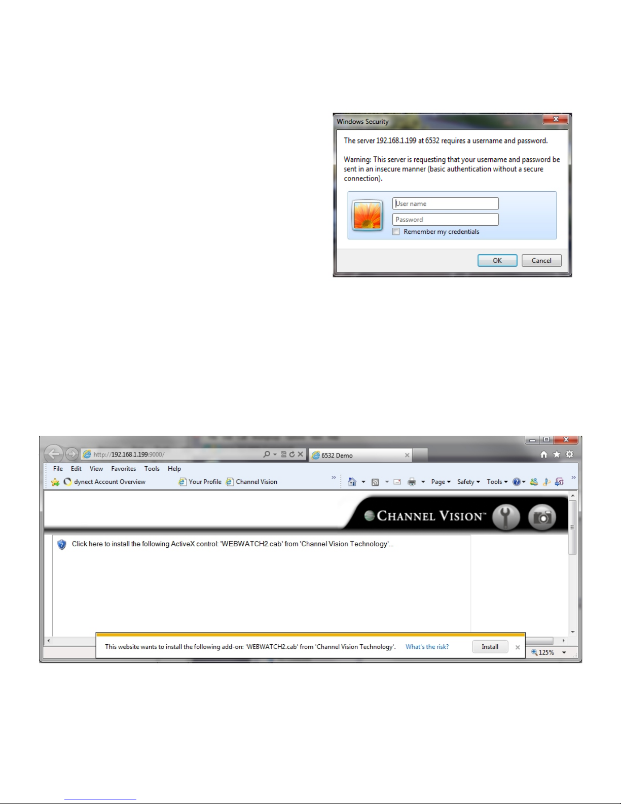
Connecting To The IP Camera (Static)
1. The first time you connect to the camera via Internet Explorer, it will ask you to install the
ActiveX control. Internet Explorer 6, 7, 8, or 9 must be used to run this ActiveX control.
1. Open Internet Explorer. Type the IP address of the IP camera into the browser link window.
Also, make sure to type the port at the end of the link.
For example, I will type in http://192.168.1.199:9000
2. You will be prompted for a username and password.
The default username is ‘admin’
The default password is ‘admin’
Installing The ActiveX Control
13
Page 14
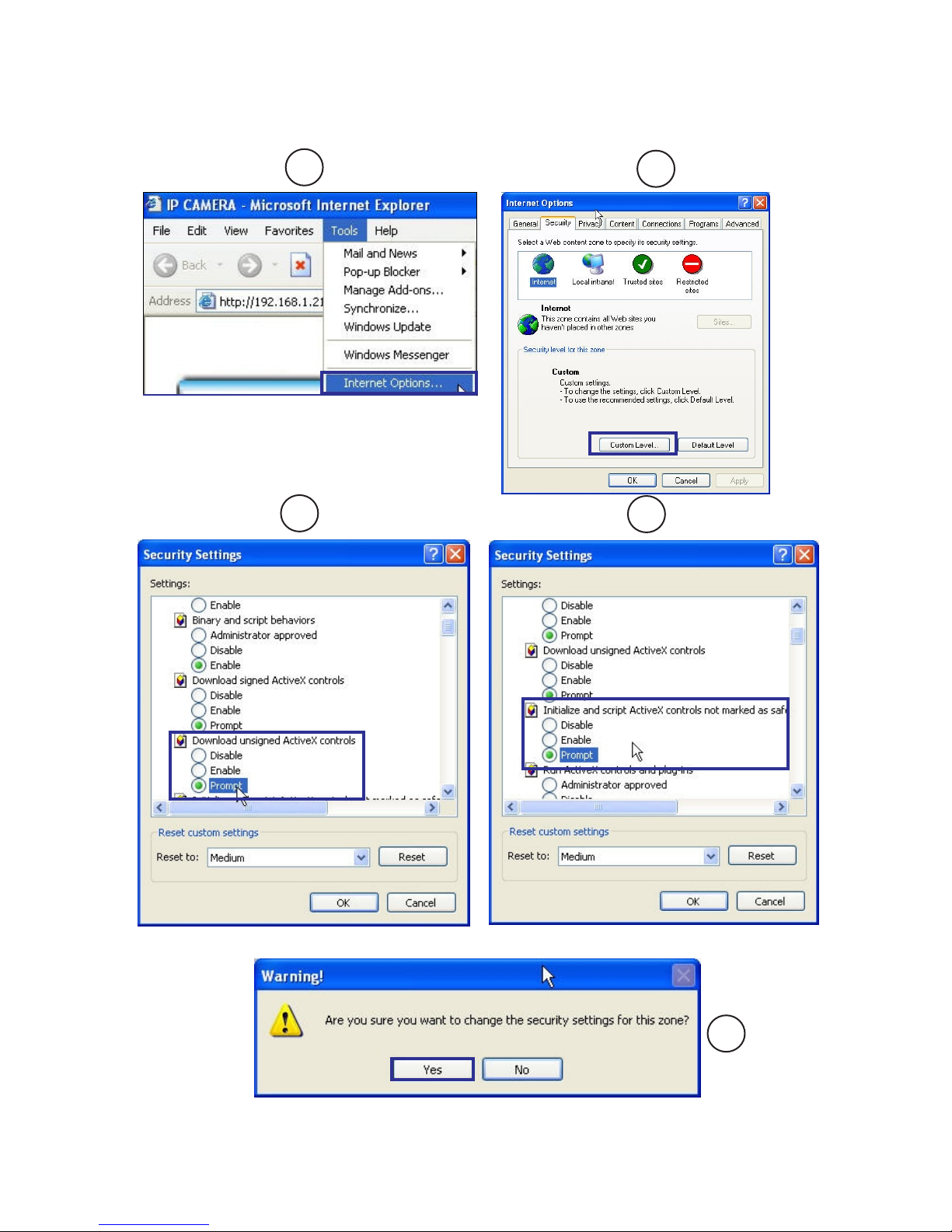
When popup the following dialogue box, click “Yes”.
If the installation of the ActiveX control fails, for example the browser page says “done” but you do not see
your camera, please check the security settings for your IE browser. Follow the instructions below.
Configuring Internet Explorer
1
2
3
4
5
14
Page 15
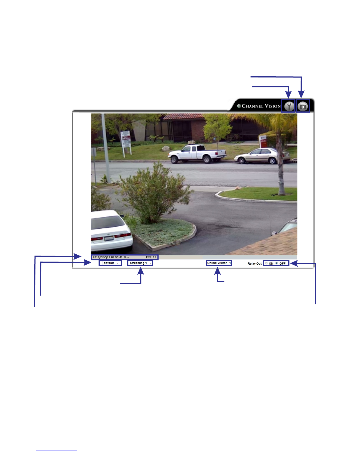
Live Viewing
Snapshot
Format: Year/Month/Day/Hour/Minute/Second/ Image Size/Frames Per Second
Controls the physical size of the streaming video on the browser screen
Controls the selection of the video
stream that is being viewed
Activates relay output
Shows the number of users
connected at any given time
Settings
Once you connect to your camera, you will see the following screen.
Below the icons and their functionality are defined.
15
Page 16
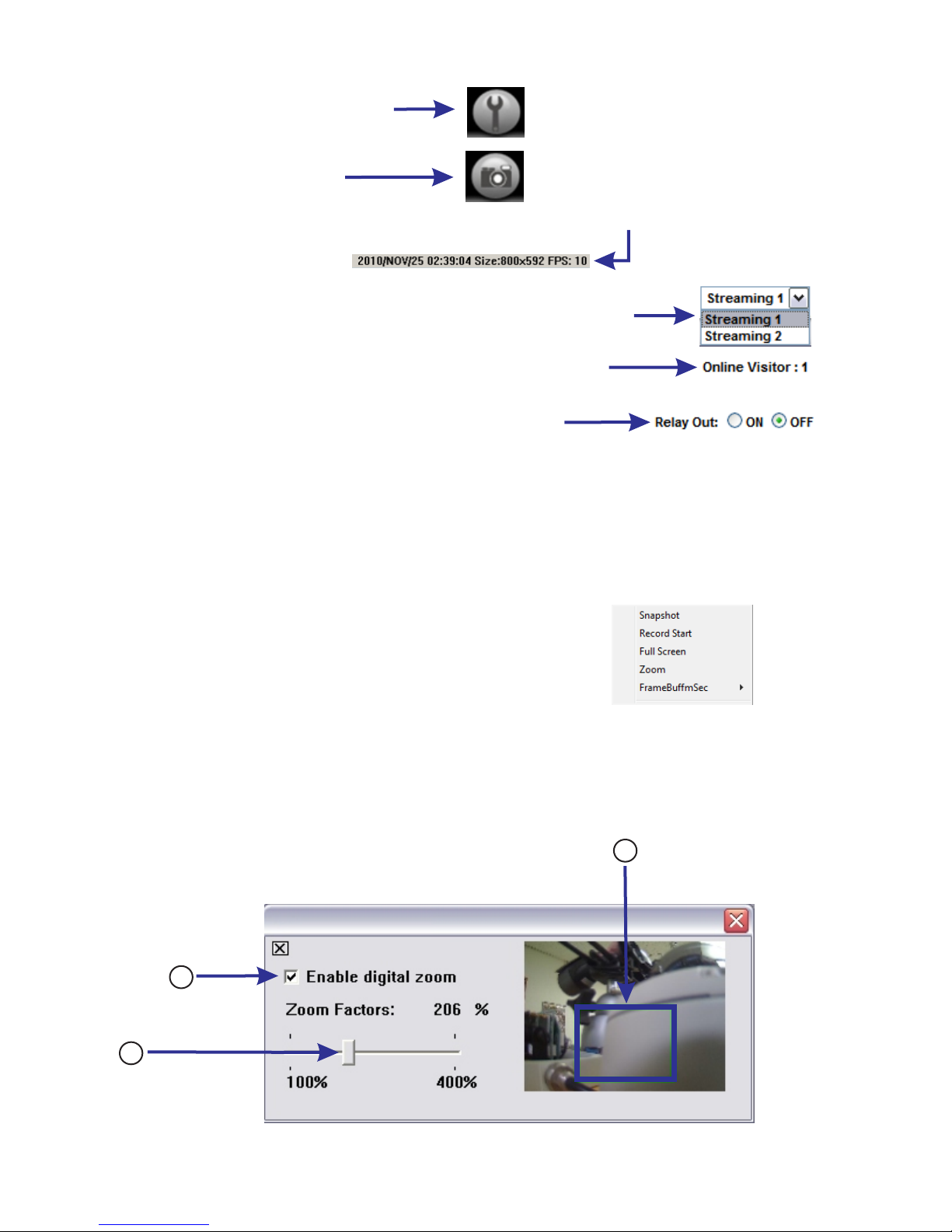
1. Th
2. This icon takes a snapshot
3. This icon shows system time, video resolution, and video refresh rate
4. The bottom bar has an icon that allows you to select which stream
you want to view. Stream 1 is usually the larger, better quality stream.
Stream 2 is the smaller stream, generally used for mobile viewing
5. The bottom bar has an icon shows how many users are connected
to the IP camera.
6. This icon will control/activate the relay output on the camera
wire pigtail. A relay can activate lights, alarms, or anything that uses a contact
closure.
7. If you double click the video feed, it will make the video full screen.
To change video back to normal mode, press ‘Escape’ on your keyboard, or double
click anywhere in the video feed a second time.
8. If you right click on the video, you have access to several different functions.
A. Snapshot: Takes a snapshot
B. Record Start : Records video to your computer
C. Full Screen: Click to enter full-screen mode
D. Zoom: Digital Zoom. This is explained below
E. Frame BuffmSec: This changes the frame buffer rate
(Increasing the buffer rate will provide a smoother video stream)
Digital zoom
1. Select “Enable digital zoom”
2. Select the area of the screen you wish to zoom (up to 400%)
3. Select the zoom level
is icon opens the settings menu
Live Viewing/cont.
1
3
2
A.
B.
C.
D.
E.
16
Page 17
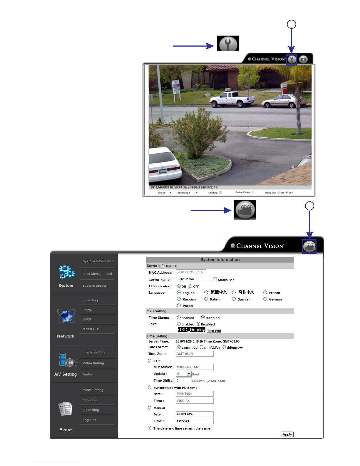
Configuration
1. Select this icon to enter the settings menu
2. Select this icon to go back to your live video feed
1
2
17
Page 18
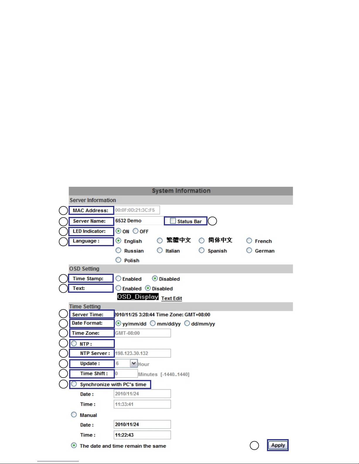
System Information:
Use the number scheme below for a description of each item:
1. MAC Address: (Media Access Control) address; This is a unique identifier assigned to IP devices for
communication with the network. Your IP camera is pre-set with a MAC address
2. Server name: Select to edit the camera name
3. LED Indicator: Select On/Off to toggle the blinking LED light in the camera
4. Language: Select a language to change the language of the ActiveX interface
5. Status Bar: Select On/Off to toggle the information bar (below the main video stream)
6. Time Stamp: Select Enabled/Disabled to turn the video timestamp on or off
7. Text: Select Enabled/Disabled to specify the name that can be displayed on the top left area of the screen
8. Server Time: This shows the current time on your IP camera
9. Date Format: Select to choose your desired date format
10. Time Zone: This shows your current time zone
11. NTP: The Network Time Protocol is a protocol for synchronizing the clocks of computer systems
12. NTP Server: If you have a NTP server, input it here
13. Update: If using an NTP server, select this drop down menu to choose the update interval
14. Time Shift: Time shift is used to compensate for the time it takes to server to process the sync request
for your time. This is usually not needed.
15. Synchronize with PC’s time: Select this to match your computer’s clock to your IP camera
16. Apply: Select this button to save your changes
System Configuration
1
3
2
4
8
10
12
9
11
13
14
15
16
5
6
7
18
Page 19
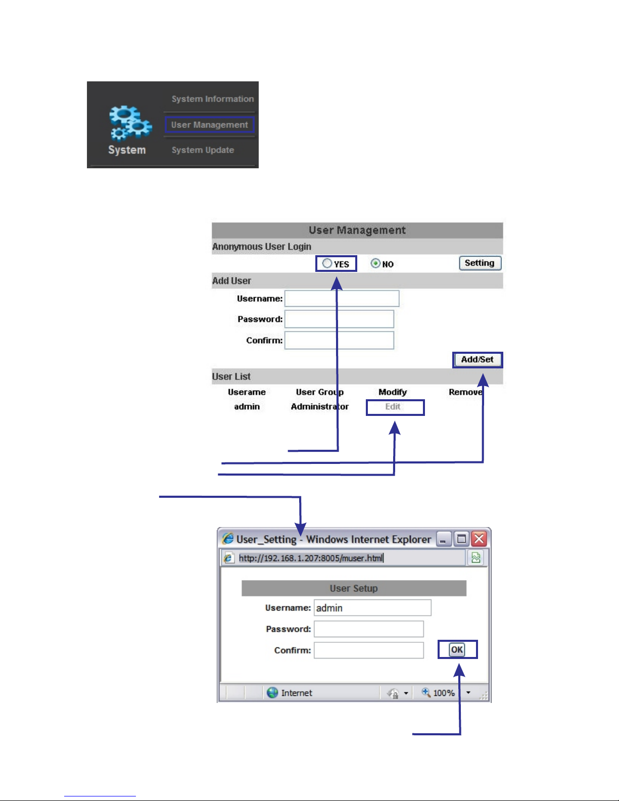
User managment:
This IP camera supports 3 different types of users.
1. Administrator
2. General
3. Anonymous
Click “Yes” to allow anonymous user access
Click “Add/Set” to add a user
Click “Edit” to modify a user.
When you click edit, the following window will pop up:
(Shown below.)
Add the username and password, and click “OK” to save your new user.
User Management
19
Page 20
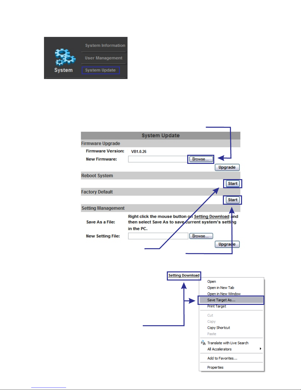
System Update: This menu is used to perform the following functions:
1. Firmware Update: Channel Vision will update the firmware from time to time.
By registering your IP camera, you have access to all firmware improvements
and extended warranty options.
How? See the product page on www.channelvision.com
To load new firmware, press “Browse” and select the firmware.bin file.
2. Restart System: Select to restart system.
You can reset the IP camera to factory default settings if desired
If you backup your settings, you can load your backup file where it says “New Setting File”
3. Settings backup:
You can backup your settings by right clicking your
mouse on “Setting Download” and selecting
“Save Target As”. You may also load previously saved
settings files this way. When loading previously saved files,
click “Browse” and then “Upgrade”
System Update
20
Page 21
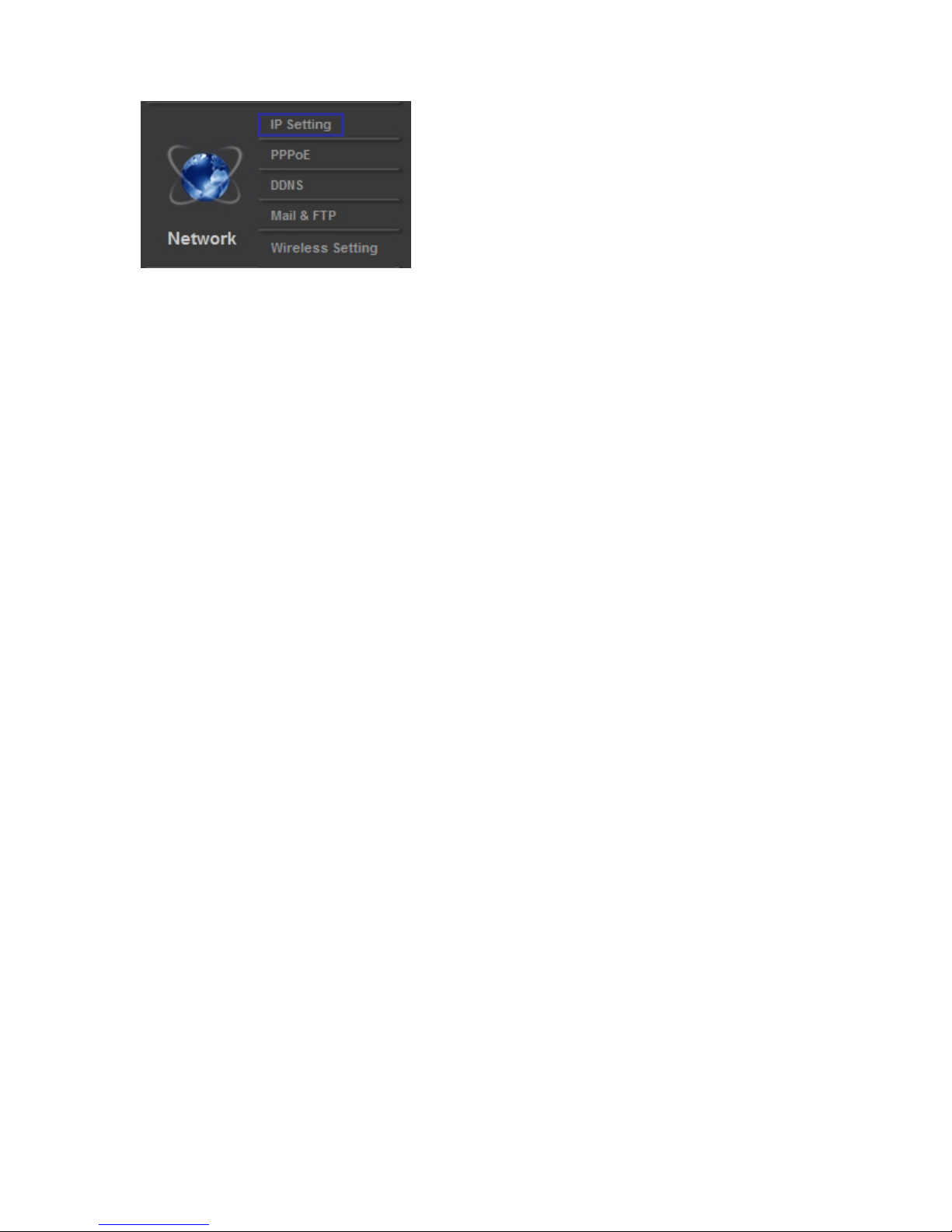
Network Setup/IP Setting: This setting is for the external viewing of camera over the internet.
Once set up, you will be able to view this camera from anywhere in the world.
This IP camera supports DHCP and Static settings.
If you are new to installing an IP camera, use #2 (Static IP)
DHCP: If you use this setting, your IP information will be pulled automatically from
your router. This not recommended if you are going to view this camera outside of
the building that it resides in.
Static IP: This is an IP that you manually set. This IP must not be the same as
any other device within your network. You must also set default gateway, DNS server,
subnet mask, and DNS server. Please refer to page 6 & 7 for instructions
on how to obtain these numbers.
Port Assignment: You can assign different ports for your camera.
(Explained below.)
Web Page Port: (This is the port that 99% of installations will use)
A web page port is used to transmit data out of your network. For example,
If my external IP address is http://67.88.12.50, and my port was 5400,
I would put a “:” and the port. The final address would be http://67.88.12.50:5400
RTSP Transmitting Port: Port for RTSP stream. Used for many automation systems.
RTP start and end port:
In RTSP mode, you may use TCP and UDP for connecting
TCP connection uses RTSP port (554) UDP connection uses RTP start & end port.
UPnP: This IP camera supports UPnP. If this service is enabled on your computer,
the camera will be automatically detected and a new icon will be added to
“My Network Places”.
Below are instructions on how to activate UPnP on your computer:
A. Open the control panel from the start menu.
B. Select “Add/Remove programs”
C. Select “Add/Remove Windows components”
D. Open “Networking Services” section
E. Click “Details” and select UPnP to setup the service.
F. Once activated, the IP camera icon will appear in “My Network Places”
G. You can now double click that icon to access the camera with your IE browser.
Network
21
Page 22
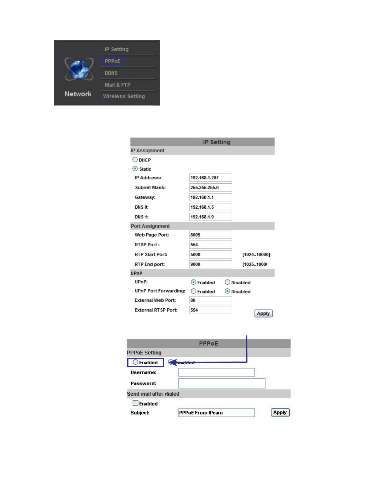
Network/cont:
IPV4: Below is an example of the IPV4 network settings menu. This is where you key in all of your IP
information from your network. These settings must be entered correctly in order for the IP camera to be
viewable over the network.
Network/cont
PPPoE: Check the PPPoE “Enabled” button to activate this function.
You can key in a username and password for the connection if you are using ADSL.
Send mail after dialed: When connected to the internet, this IP camera will send a
email to the specified email account. To configure the IP camera email settings,
please refer to the “Mail and FTP Settings”
22
Page 23
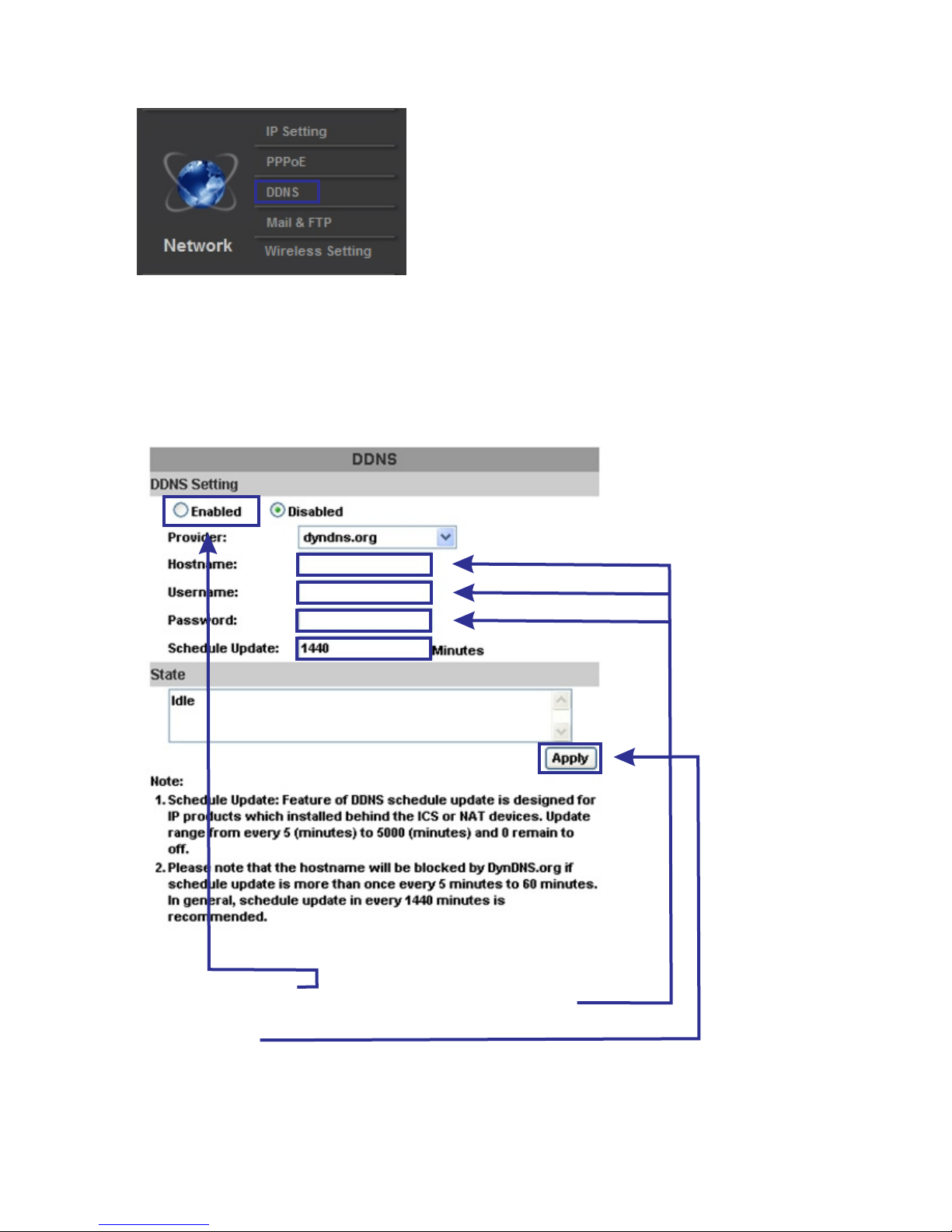
Network/cont: DDNS:
This IP camera supports DDNS (Dynamic DNS) service.
Select “Enabled” to enable the DDNS service.
For viewing the IP Camera over the internet while using a dynamic (rotating) IP address,
there are many services available online.
1. Enable the service
2. Key in the DynDNS server name, username, and password
3. Set up the IP update refresh rate
4. Click “Apply”
5. If it updates to often, the IP will be blocked by DynDNS
Channel Vision recommends you set it to update once per day (1,440 minutes)
Network/cont
23
Page 24
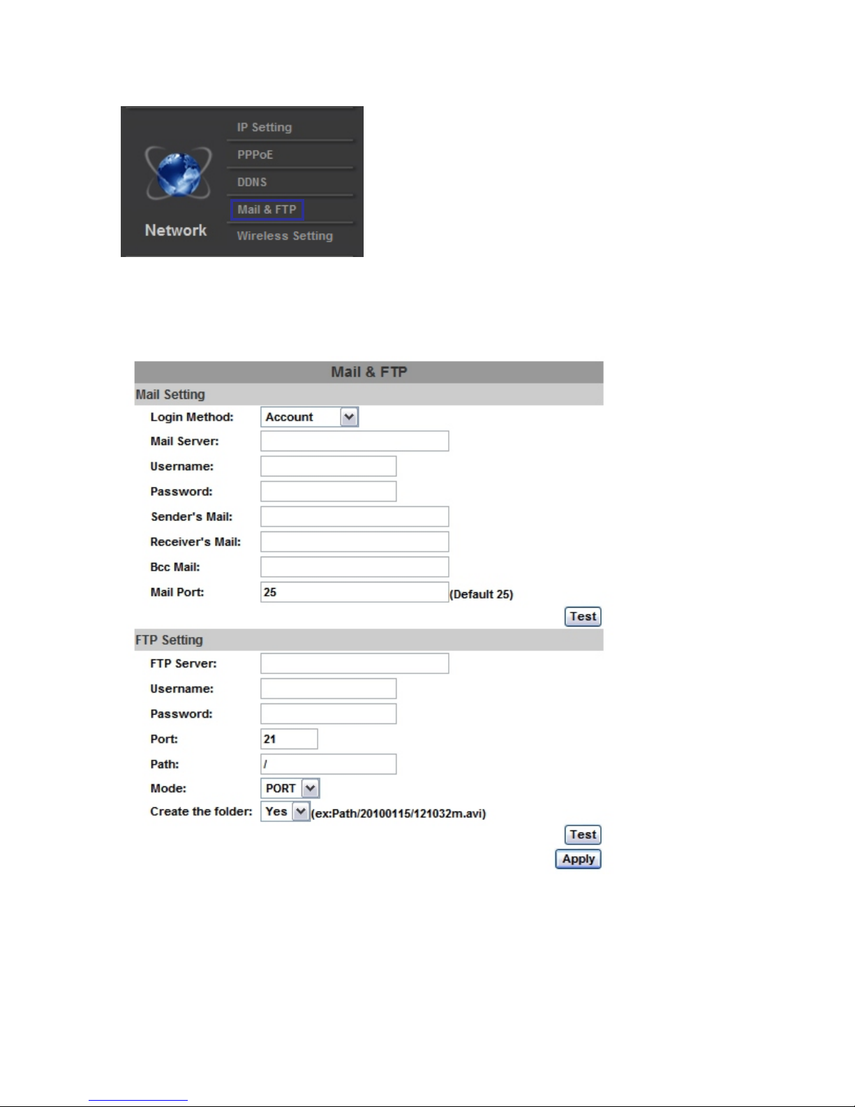
: Enter your Mail and FTP information into the menu below:
Mail: Mail is a way the IP camera can send you an email when certain actions occur, for
example motion, a contact closure on the sensor, etc.
FTP: FTP is for uploading recorded files to a designated FTP site
Please note: standard free web mail email services block devices such like this, due to spam
settings.
Mail & FTP
Network/cont
24
Page 25
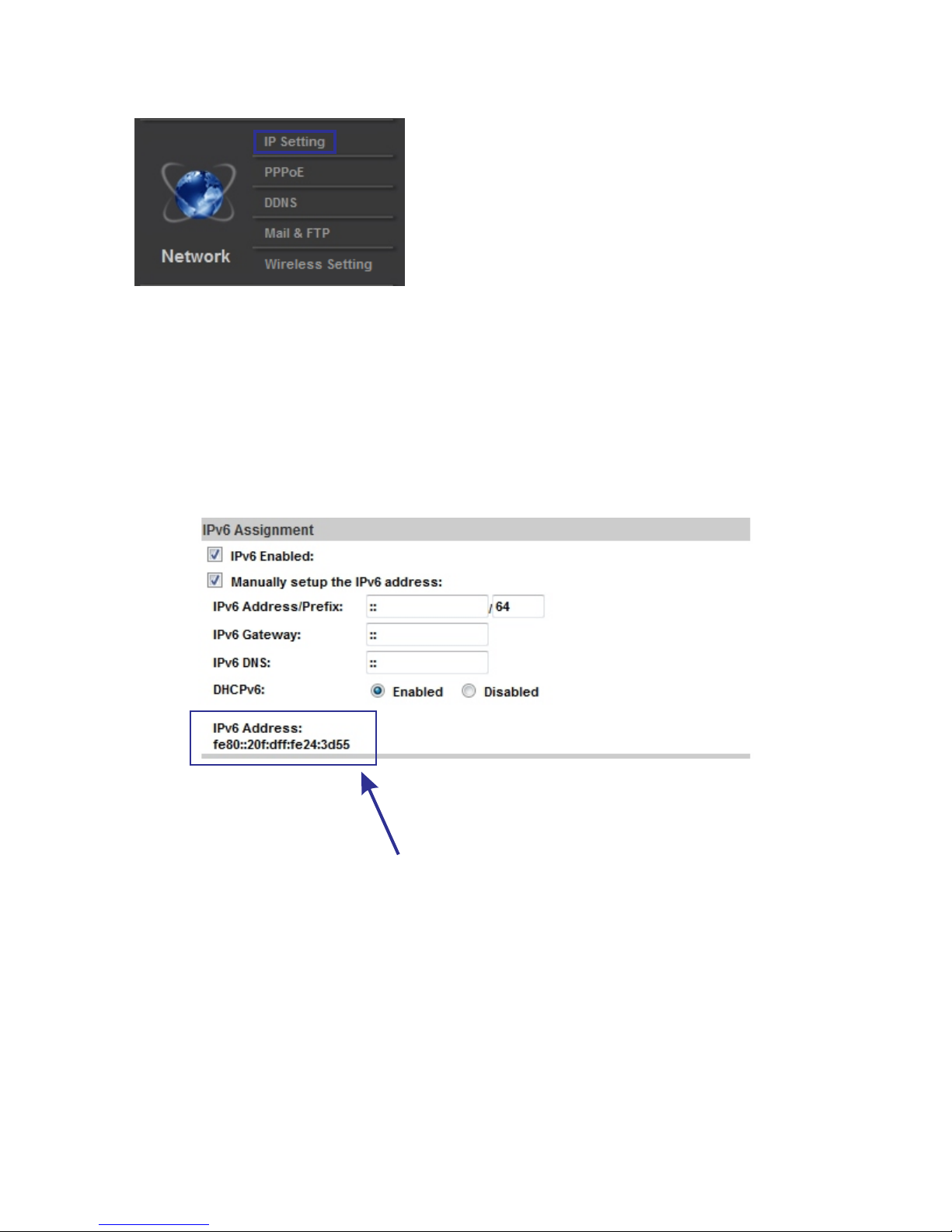
Network/cont
Network/cont, IPV6: Below is an example of the IPV6 network settings menu. This is where you key
in all of your IP information from your network. These settings must be entered correctly in order for
the IP camera to be viewable over the IPV6 network.
To manually set your IPV6 address, select that option, and enter your address, gateway, and DNS
server.
For DHCPv6, click “enabled”
Your current IPV6 address
25
Page 26
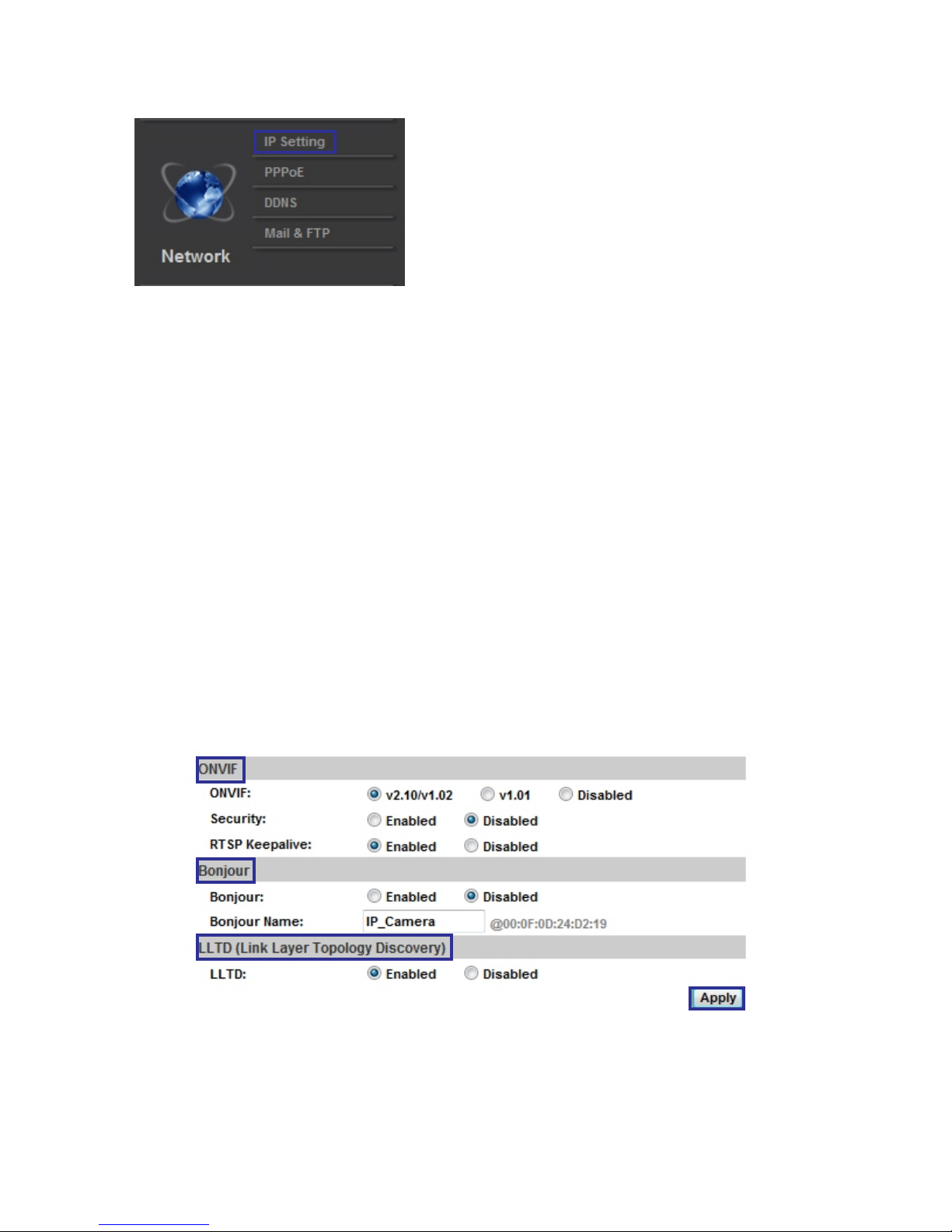
ONVIF, Bonjour, LLTD
26
1. ONVIF: (Open Network Video Interface Forum)
ONVIF is a global and open industry forum with the goal to facilitate the development and
use of a global open standard for the interface of physical IP-based security products
The following ONVIF versions are supported: 1.01, 1.02, and 2.10.
There are also custom options available, such as security and RTSP keep alive that may be
specified by the ONVIF supported device. When RTSP keep alive is enabled, the camera checks
every hour to see if the device linked to the camera via ONVIF is still connected. If the connection
stops, the IP camera stops transmitting video out.
2. Bonjour: This is Apple's implementation of Zero configuration networking (Zeroconf), a group of
technologies that includes service discovery, address assignment, and hostname resolution.
Bonjour locates devices such as printers, other computers, and the services that those devices
offer on a local network using multicast Domain Name System (mDNS) service records.
To enable Bonjour, click “enabled” and specify the name of the IP camera.
3. LLTD: (Link Layer Topology Discovery)
LLTD is a proprietary Link Layer protocol for network topology discovery and quality of service
diagnostics. Microsoft developed it as part of the Windows Rally set of technologies. The LLTD
protocol operates over both wired (such as Ethernet (IEEE 802.3) as well as wireless networks
(such as IEEE 802.11). To Enable LLTD, select “enabled”
Bonjour is a trademark of Apple Inc., registered in the U.S. and other countries
Page 27
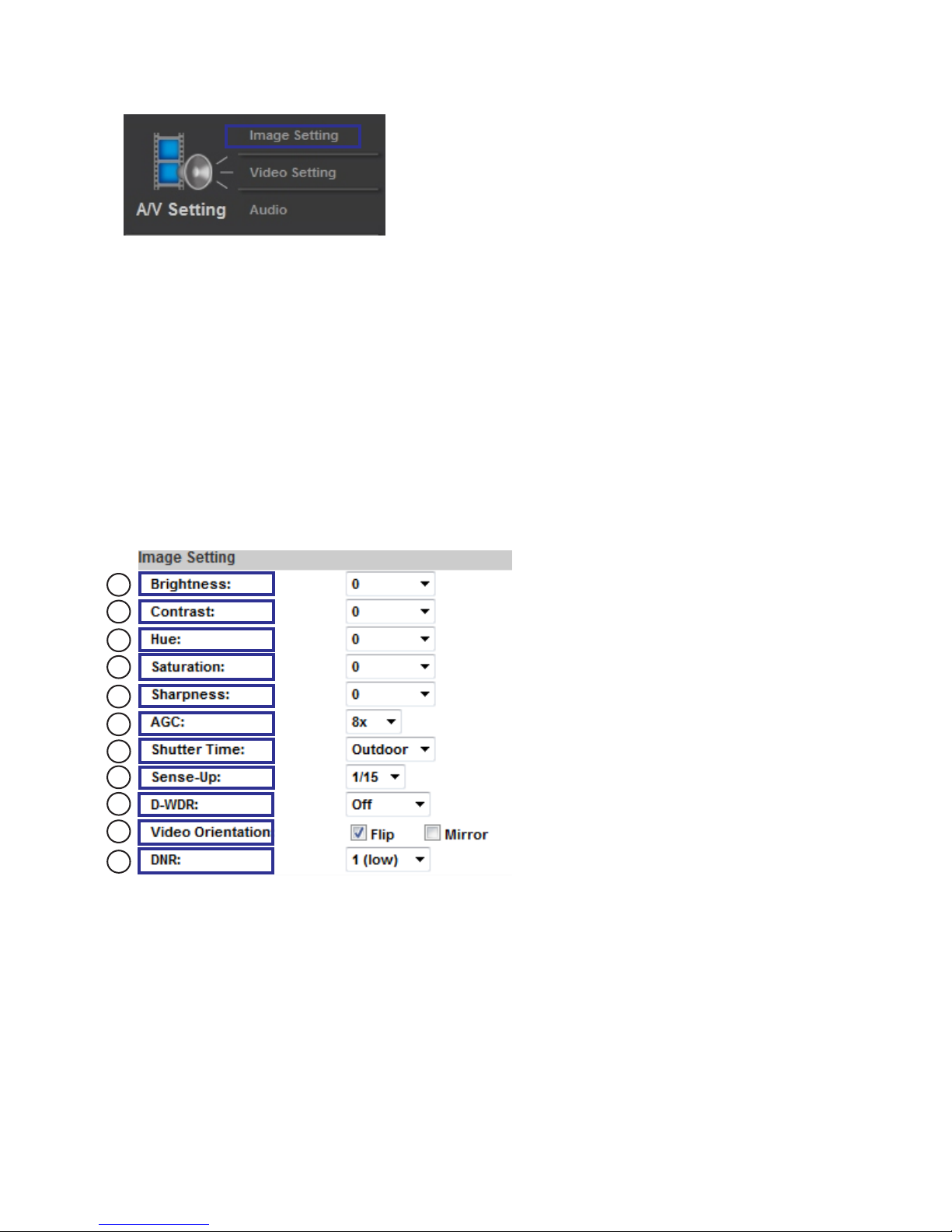
Video Settings
Image Setting: You can adjust the following items on this camera:
1. Brightness: This adjusts the brightness level of the camera
2. Contrast: This adjusts the difference in color and light between parts of an image
3. Hue: This adjusts the hue of the camera
4 Saturation: This adjusts the color saturation of the camera
5. Sharpness: This adjusts how sharp the image appears
6. AGC: This adjusts the automatic gain control for night viewing
7. Shutter Time: This adjust the shutter speed to reflect various lighting conditions
8 Sense-Up: This allows adjustments of selectable digital slow shutter speeds
9. D-WDR: This adjusts digital Wide Dynamic Range, for bright to dark lighting
10. Video Orientation: This adjusts video orientation
11. DNR: This allows adjustment of digital noise reduction
1
2
3
4
5
6
7
8
9
10
11
27
Page 28
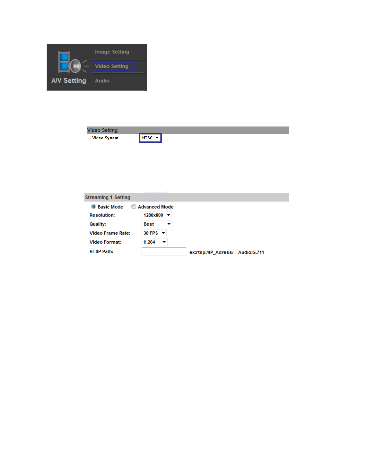
Video Settings/cont.
Video Setting:
Click the drop down list to select Video System
Streaming: Basic mode:
1. Resolution:
There are 5 resolutions you can choose from.
3. Video Frame ate: The video refresh rate per second. Setting max is 30 FPS
4.
5. RTSP Path: RTSP output name.
For example, if I choose camera, the rtsp path would be as follows: rtsp://camera/V2
2. Quality:
There are 5 levels you can adjust to:
Best, High, Standard, Medium, & Low
If you use the highest settings, the network streaming speed will be slower
Also, if you record any files, the higher the quality, the larger the file will be
R
Video Format: This describes the codec use for compression. H.264 is newer
and higher quality, and MJPEG (JPEG) is an older standard
1920x1080, 1280x720, 640x480, 320x240, 126x144
28
Page 29
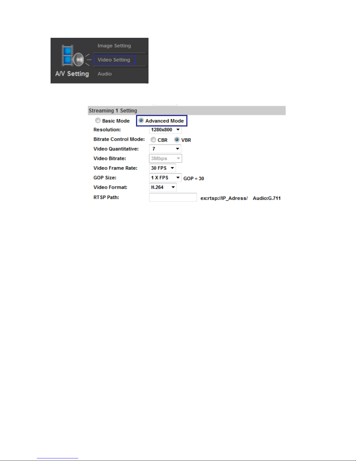
Streaming (Advanced Mode):
1280x720
640x480
320x240
126x144
2. Bitrate Control mode:
There are 2 choices. CBR (Constant Bit Rate) and VBR (Variable Bit Rate)
A. CBR: 32Kbps-8Mbps (The higher the CBR, the better your video quality will be)
B. VBR: 1 (Low) to 10 (High) Compression rate. The higher the compression rate
the higher the picture quality, and vi e versa. The balance between VBR and
network bandwidth will affect your picture quality. When using VBR, it is less
likely that your streaming video will break up or lag.
3. Video Frame Rate: The video refreshing rate per second
NTSC: Max 30 frames per second PAL: Max 25 Frames per second
4. GOP Size: This means ‘Group of Pictures.” The higher the GOP is, the better
the quality of the images
5. Video Format: This describes the codec use for compression. H.264 is newer
and higher quality, and MJPEG (JPEG) is older, but used in some control systems
6. RTSP Path: RTSP output connecting route for example,
1. Resolution:
c
rtsp://camera/v1
There are 5 resolutions you can choose from.
1920x1080
Video Settings/cont.
29
Page 30
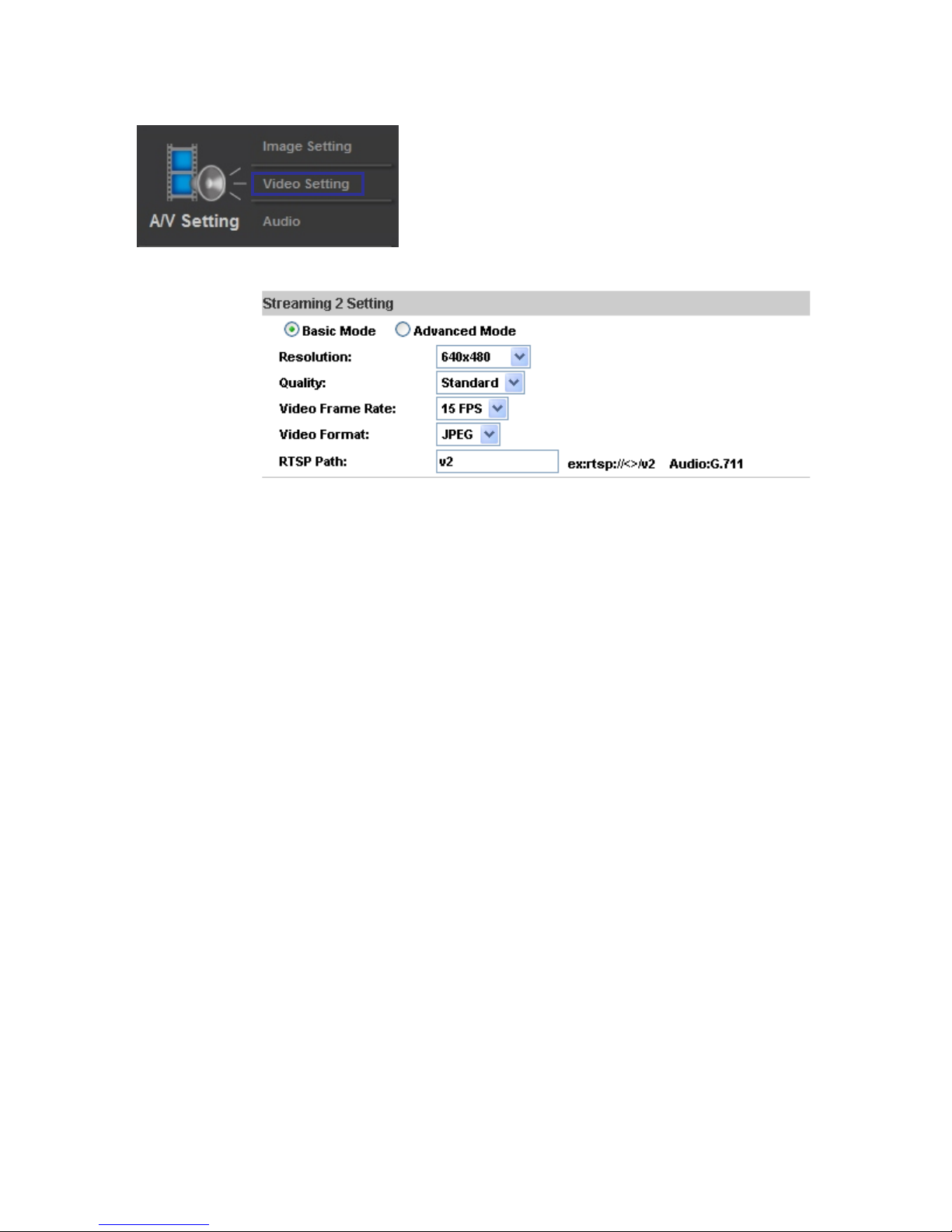
Stream ( Mode):
1280x720
640x480
320x240
126x144
2. Quality:
There are 5 levels you can adjust to:
Best, High, Standard, Medium, & Low
If you use the highest settings, the network streaming speed will be slower
Also, if you record any files, the higher the quality, the larger the file will be
3. Video Frame Rate: The video refreshing rate per second
This describes the codec use for compression. H.264 is newer
and higher quality, and MJPEG (JPEG) is older
. RTSP Path: RTSP output connecting route
2 Basic
1. Resolution:
There are 5 resolutions you can choose from.
4. Video Format:
5
For example, rtsp://camera/v2
1920x1080
Video Settings/cont.
30
Page 31
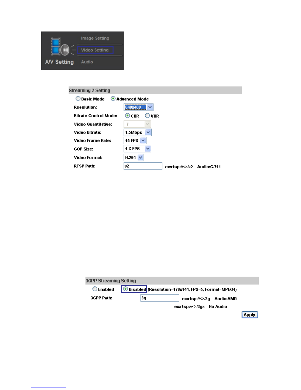
Stream Mode:
1920x1080, 1280x720, 640x480, 320x240, 126x144
2. Bitrate Control mode:
There are 2 choices. CBR (Constant Bit Rate) and VBR (Variable Bit Rate)
3. Video Frame Rate: The video refreshing rate per second.
4. GOP Size: This means ‘Group of Pictures.” The higher the GOP is, the better
the quality of the images.
5 This describes the codec use for compression. H.264 is newer
and higher quality, and MJPEG (JPEG) is older
6. RTSP Path: RTSP output connecting route.
2 Advanced
1. Resolution:
There are 5 resolutions you can choose from.
. Video Format:
.
7. 3GPP Streaming Mode:
1. Enable or Disable 3GPP Streaming
2. 3GPP: 3GPP output name
*Channel Vision recommends you use 176x144 resolution, 5FPS, MPEG4 format for 3GPP mode
Video Settings/cont
31
Page 32
Recommended Video Settings
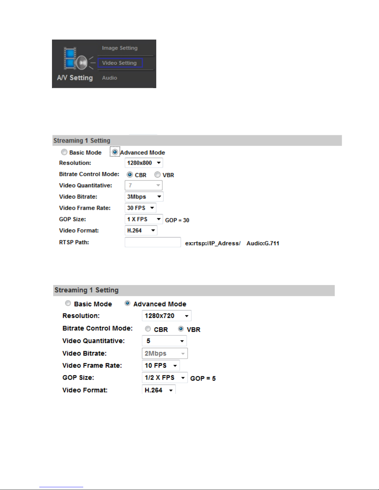
Below are a few examples of recommended settings, depending on the situation.
1. Viewing a stationary object, or area that does not receive a high amount of movement
If the camera is looking at a stationary object, or an area that does not receive a lot of traffic or
movement, the camera can be set to the highest settings. An example of the highest settings are below:
2. Viewing an area that receives a high amount of traffic or movement
If the camera is looking at an area that views constant or near constant movement, a medium setting
is recommended. An example of medium settings are below:
32
Page 33
Recommended Video Settings/cont
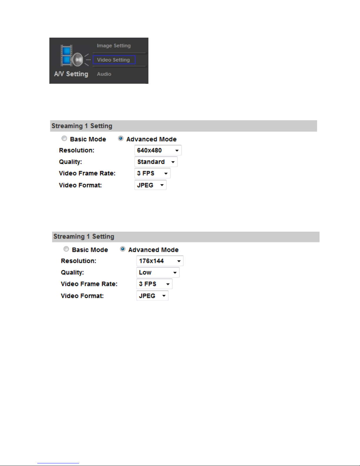
4. Viewing the IP Camera on the lowest settings
Below is an example of the lowest settings.
3. Viewing on a slow internet connection
If the IP Camera is installed on a network that does not have a very fast internet connection,
or you are viewing on a network with limited bandwidth, the example below is recommended.
33
Page 34
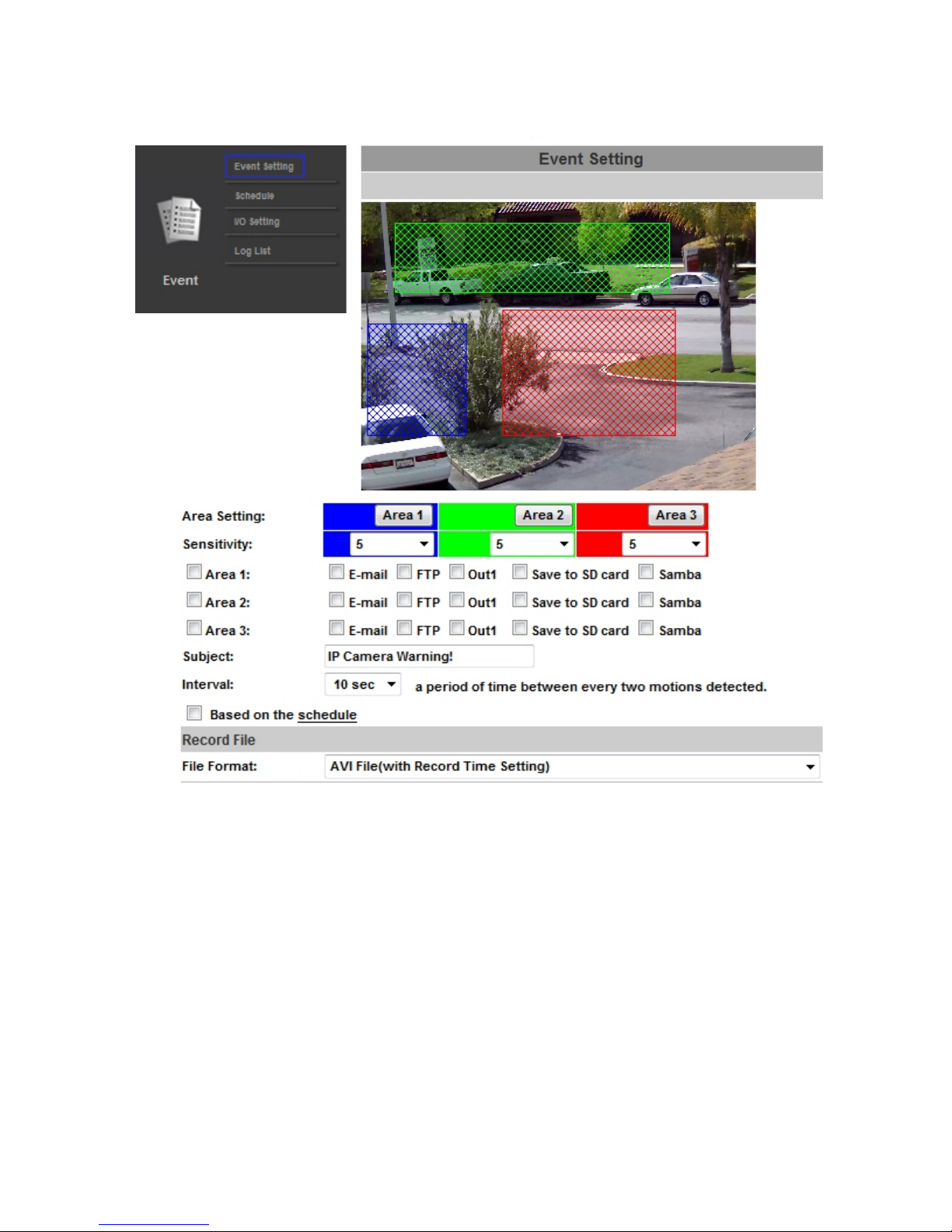
Event List
34
1.) Event Setting: The purpose of this menu is to configure what the camera will do when
an “event” is generated.
2.) Motion Detection
This IP Camera allows 3 areas of motion detection. (Area Setting) When motion is triggered,
they can send the video, in the form of events to a specific mail address, transmit the live video
to a remote FTP server, & trigger a relay.
To set up the motion area, click “Area Setting”. Use the mouse to click and
drag a box of the area you want to select. The same method is used for area 2 and area 3.
.3.) Record File Setting: The IP camera allows 3 different types of recorded files.
A.) AVI File (With time stamp) This is the largest file size option to choose, but the video will
be the highest quality available.
B.) JPEG (MJPEG) File (With time stamp) This is a smaller file size to choose, but is of lower
quality than the AVI format.
C.) JPEG (MJPEG) Single file with interval setting.
Page 35
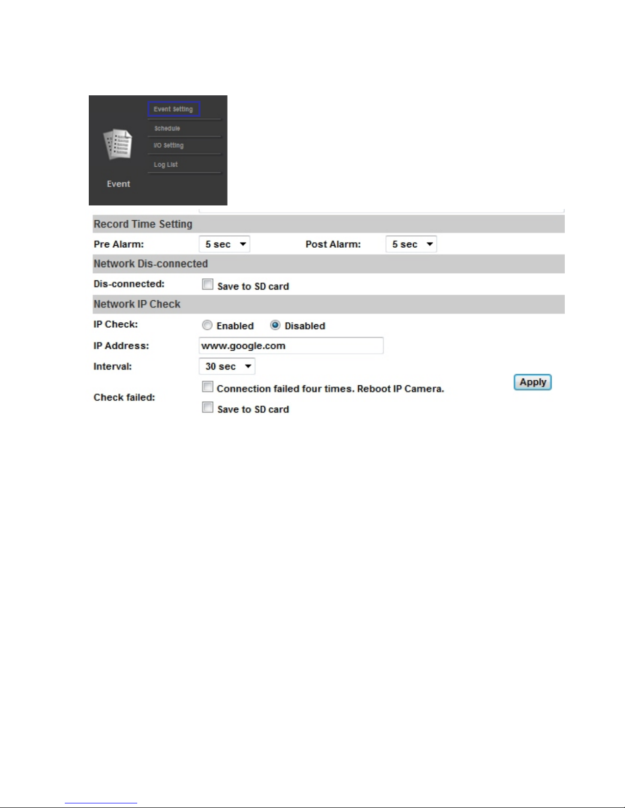
4.) Record Time Setting:
Pre Alarm and Post Alarm setups for record start and end time when motion is detected, or to trigger a relay.
Note: Pre/Post Alarm record time based on record time setting and IP Camera's built-in memory. The ability
to store data is limited, so if the video quality is set very high, this will cause a drop in the recorded FPS.
This will also decrease pre or post recording time.
5.) Network Dis-connected:
To avoid loss of data, the IP camera will start to save the video to a Micro SD card (if installed) when it
detects that the Ethernet cable has been unplugged. The video will continuously be saved into Micro SD
card, divided into 5 minute increments, until the network is reconnected. When the SD card is full, it will
automatically overwrite the oldest file, one at a time.
This will only function automatically when first wired to a network, and “Save to SD card” is selected.
6.) Check Failed:
This option checks your internet connection (Interval) to make sure your network connection has not been
lost.
Event List/cont.
35
Page 36
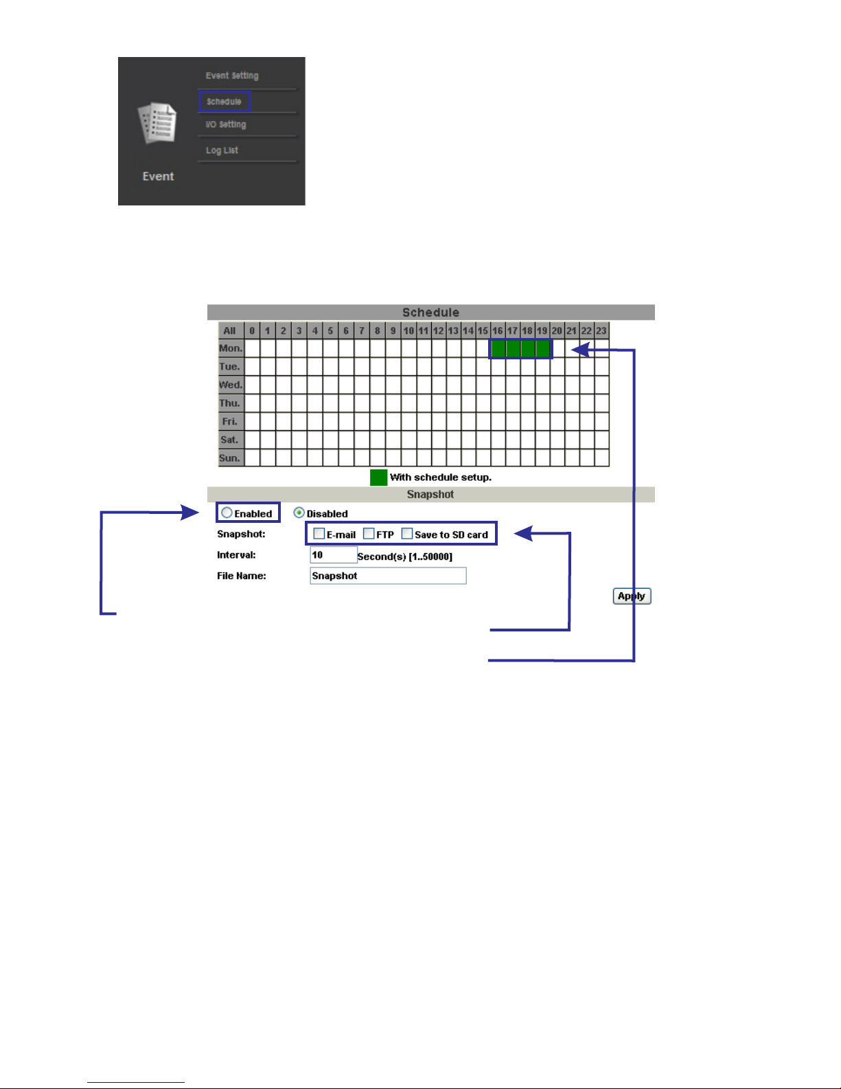
1.) Schedule: Complete schedule setup to tell the IP Camera when to record data.
2.) Snapshot: After enabling the snapshot function, user can select the storage
location of the snapshot, the time of snapshot, and the file name of snapshot.
Schedule
Supported SD Cards
Click “Enabled” to enable snapshot.
Select the E-mail, FTP, or Save to SD card option to enable.
Click the desired areas (boxes) to designate recording time.
Green=record
36
Transcend
SDHC class4 16GB
SDHC class4 32GB
SD class4 16GB
SD class4 32GB
SDHC class6 4GB
SDHC classs 8GB
SDHC class6 16GB
SD class6 4GB
SD class6 8GB
SD class6 16GB
SDHC class10 4GB
SDHC class10 8GB
SDHC class10 16GB
SanDisk
SDHC class 44GB
SDHC class 48GB
SDHC class 416GB
SDHC class 432GB
Page 37
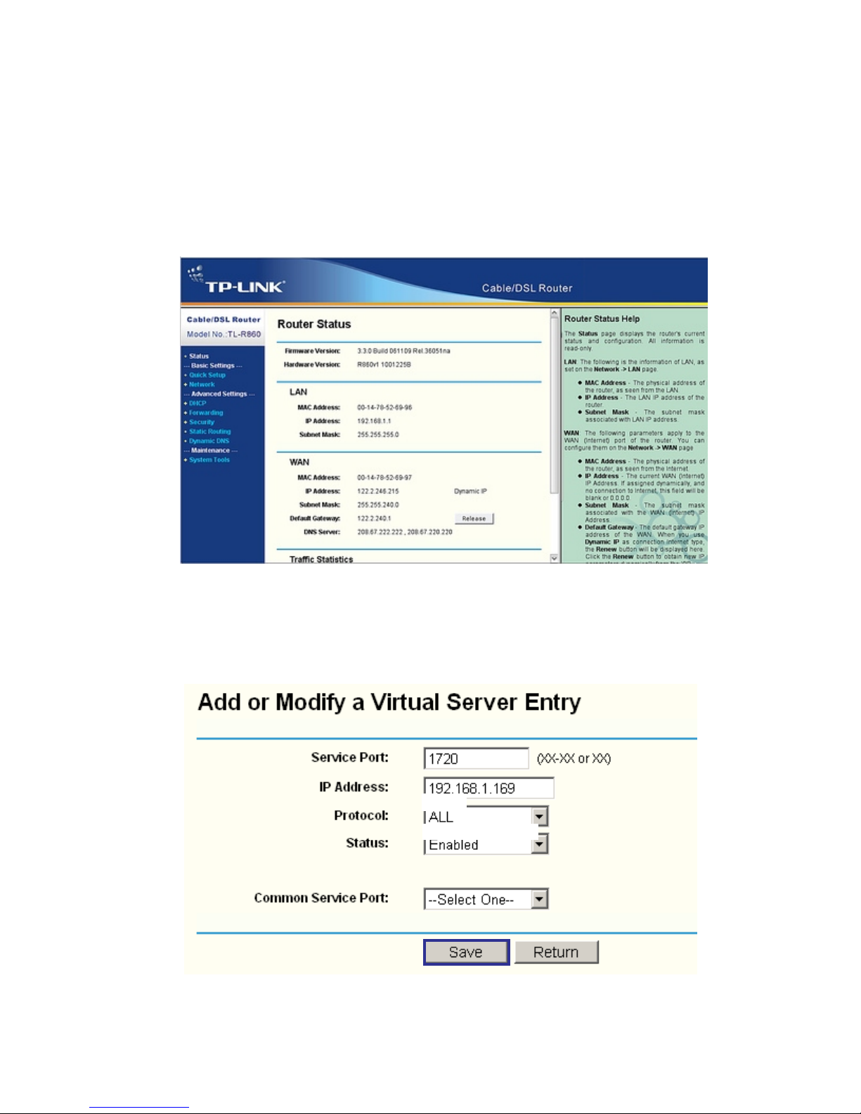
Port Forwarding
Port Forwarding TP-Link Routers
In order to view the IP camera from outside of your home or business network, port forwarding configuration
will be required in your router.
In the example below, there is a IP camera running on
port 8002 on the LAN.
1. Add the IP information, including the desired port into the port forwarding tab of “forwarding” in the router
2. Check “Enable Port Forwarding”
3. Select “Add or Modify a Virtual Server Entry”
4. Select and add “service port” as port of the camera
5. Enter IP address of camera under “IP address
6. Change Protocol to “all”
7. Change status to “enabled”
8. Select “Save” to save changes
37
8000
192.168.1.222
TPLINK is a registered trademark of TP-link Technologies CO. LTD.
Page 38
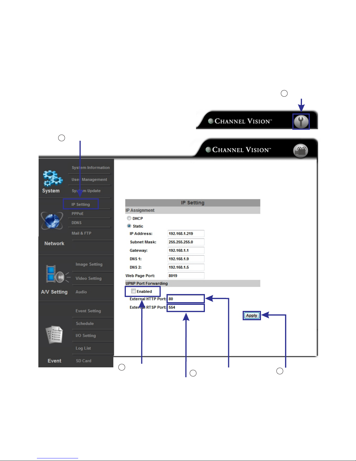
Click “enabled”
Click “IP setting”
Generally unused, not required
Click “Apply”
This is required, please choose a
port for your IP Camera.
Default is 80
2
3
4
5
UPNP Port Forwarding
In order to view the IP camera from outside of your home or business network, port forwarding configuration
will be required in your router.
Alternatively, you can use what is called UpNp, or Universal Plug and Play.
Follow the instructions below to configure the IP Camera for UpNp.
By default, the IP Camera is set to port 80.
This can be changed if needed, but 80 (industry standard for default http server port) but is not required.
Go to www.channelvision.com for detailed port forwarding, DDNS service, & Channel Vision iPhone and iPad app.
Click “Setup”
1
38
iPod and iPad are trademarks of Apple Inc., registered in the U.S. and other countries.
Page 39
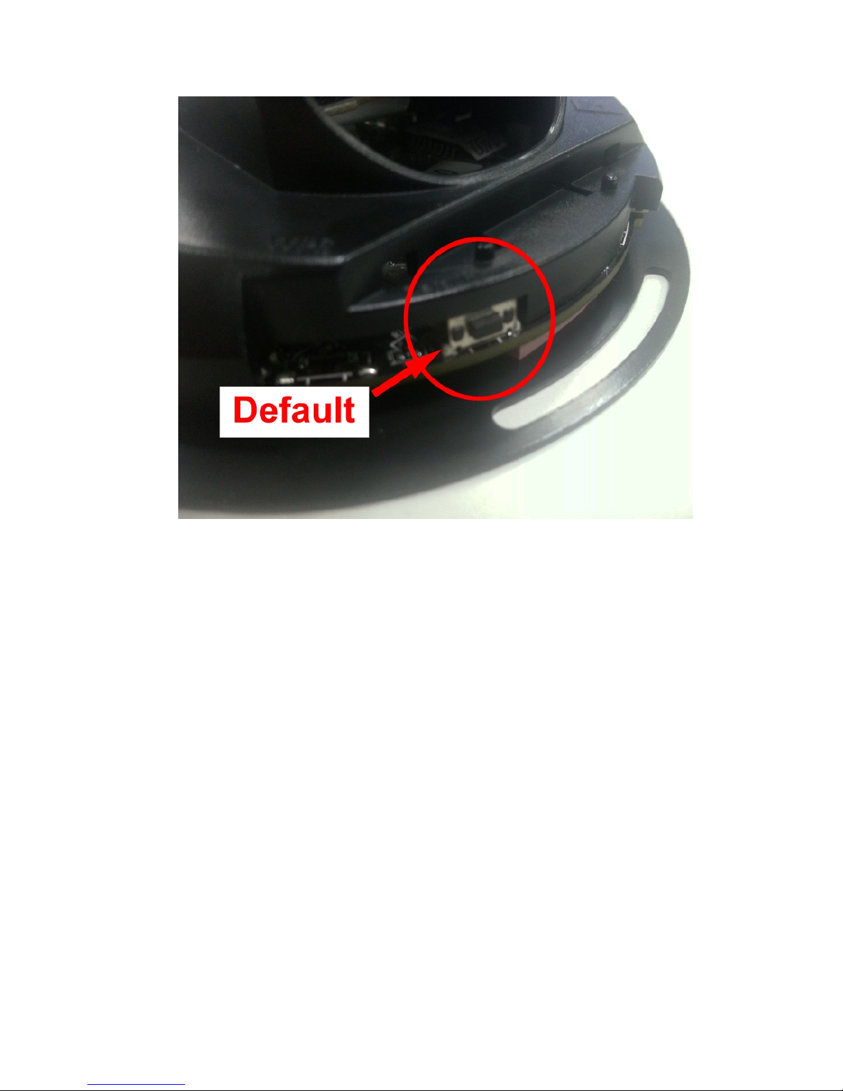
Factory Default
In some cases it may be necessary to perform a factory default on the camera. Should any issues occur with
the camera, there is a very high chance this will solve those issues.
To reset the camera, disconnect power from the camera. Then, press and hold the reset button on the camera.
While holding reset, apply power. Keep holding down the reset button for 30 seconds.
The camera will default to the following settings:
IP: http://192.168.1.200
Port: 80
User: admin
Password: admin
Page 40

IR LEDs: 6 LEDs, 850nM (16’ Illumination distance)
Ethernet: 10/100 Base-T
Network Protocol: HTTP, HTTPS, SNMP, QoS/DSCP, Access list, IEEE, 802.1X, RTSP, TCP/IP,
UDP, SMTP, FTP, PPPoE, DHCP,DDNS, NTP, UPnP, 3GPP, SAMBA, Bonjour
Max Resolution: 1920x1080
Video Resolution: 1920x1080, 1280x720, 640x480, 320x240, 126x144
Video Adjustments: Brightness, Contrast, Hue, Saturation, Sharpness, Shutter speed, AGC,
Sense-up, D-WDR, Flip, Mirror, Noise Reduction, Day & Night adjustable
Motion Detection: Yes, 3 different areas
Triggered Action: Mail, FTP, Samba
Security: Password protection, IP address filtering, HTTPS encrypted, 802.1x port based
authentication for network protection, & QoS/DSCP
Vandal Proof: Yes
Motion Detection: Yes, digital only
Maximum Users: 10
Micro SD Card Management: Recording Trigger: Motion Detection, IP check, Network break down,
Schedule Video Format: AVI, JPEG Video Playback: Yes
Delete Files: Yes
OS: Windows XP, 7, or 8 recommended
Browser: Microsoft IE 6.0 or above
Suggested Hardware: Intel Dual Core 1.66G,RAM: 1024MB, Graphic card: 128MB
OS: Windows XP, 7, 8, or Macintosh version 10.6 or newer
Browser: Microsoft IE 6.0 or newer, Safari, Firefox, & Chrome
Suggested Hardware: Intel Dual Core 1.66G,RAM: 1024MB, Graphic card: 128MB (Windows)
*Specifications subject to change without notice
CPU: Multimedia SoC
RAM: 256MB
Flash: 16MB
Image Sensor: 1/2.7" CMOS Sensor
Sensitivity: Color : 0.1Lux (AGC ON)
B / W: 0.05 Lux (AGC ON)
Lens Type: 2.8mm
Power Over Ethernet: PoE Max: 802.3af, 4.32W(IR ON); 3.36W (IR OFF)
Power: 12vDC max 2.40 Watts (IR OFF)
Operating Temperature: 14° F - 113° (-10°C - 45°C)
Dimensions: 3.94" (W) x 1.93" (H)
Field Of View: 111.10°(H), 65.10°(V)
Weight: 6.35 Ounces
I/O: 1 input, 1 output
Specifications
System Requirements (Setup)
39
System Requirements (Live Viewing)
Page 41

500-391 rev B
1
Channel Vision Technology will repair or replace any defect in material or
workmanship which occurs during normal use of this product with new or rebuilt
parts, free of charge in the USA, for one year from the date of original
purchase. This is a no hassle warranty with no mail in warranty card needed.
This warranty does not cover damages in shipment, acts of God, failures
caused by other products not supplied by Channel Vision Technology, or
failures due to accident, misuse, abuse, acts of God, or alteration of the
equipment. This warranty is extended only to the original purchaser when
purchased from an authorized reseller and a purchase receipt, invoice, or other
proof of original purchase date will be required before warranty repairs are
provided.
Mail in service can be obtained during the warranty period by calling (800) 8400288 toll free. A Return Authorization number must be obtained in advance and
can be marked on the outside of the shipping carton.
This warranty gives you specific legal rights and you may have other rights
(which vary from state to state). If a problem with this product develops during
or after the warranty period, please contact Channel Vision Technology, your
dealer or any factory-authorized service center.
Channel Vision products are not intended for use in medical, lifesaving, life
sustaining or critical environment applications. Channel Vision customers using
or selling Channel Vision products for use in such applications do so at their
own risk and agree to fully indemnify Channel Vision for any damages resulting
from such improper use or sale.
This device complies with part 15 of the FCC rules. Operation is subject to the following two
conditions: (1) This device may not cause harmful interference, and (2) This device must accept any
interference received, including interference that may cause undesired operation.
Tested To Comply
With FCC Standards
234 Fischer Avenue, Costa Mesa, California 92626 USA
(714)424-6500 (800)840-0288 (714)424-6510 fax
email: [email protected]
• Intelligent Entertainment • Infrastructure • Security Solutions
www.cha nn e lv is io n. c om
 Loading...