

CHANNEL SAFETY SYSTEMS t: 0845 884 7000 | w: www.channelsafety.co.uk
INSTRUCTION MANUAL - Issue 1 - 02/2014 | 1
INSTRUCTION MANUAL
CHANNEL SAFETY SYSTEMS t: 0845 884 7000
Peters eld Business Park f: 0845 884 6000
Bedford Road
Peters eld
Hampshire e: sales@channelsafety.co.uk
GU32 3QA w: www.channelsafety.co.uk
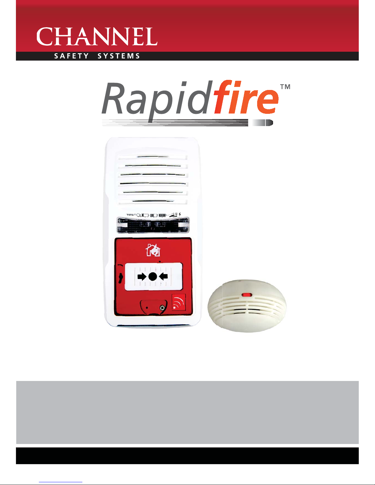
Temporary wireless battery operated re system
from Channel Safety Systems

CHANNEL SAFETY SYSTEMS t: 0845 884 7000 | w: www.channelsafety.co.uk
INSTRUCTION MANUAL - Issue 1 - 02/2014 | 2
Operating principle
When a radio linked device (MCP, stand alone alarm or
smoke detector) is in alarm, it sends the information to
the radio link alarm interface module which changes its
state (change-over contact), thus transmitting the alarm
information to the intrusion control panel (or else).
Features
• External supply : 12 V (supplied by a control panel
for example)
• Standby consumption: 0.1 mA @ 12 V
• Alarm consumption : 25 mA @ 12 V
• Indoor environment
• Operating temperature : -10°C to +50°C
Housing
• Dimensions : H 83 mm x l 83 mm x D 46 mm
• Hole pitch : 40 mm
• Colour : red
Interconnection Capacity
• Number of smoke detectors and stand alone alarm
per radio link alarm
• Interface module : non restrictive
• Up to 10 radio link alarm interface module within a
system
• Radio range in free- eld condition : 100 meters
INTERFACE PRESENTATION & FEATURES
lid fastening
screws
lid
radio link interface
module fastening
screws
radio electronic board
housing
white plastic cap
cable gland
Alarm LED
Radio LED
switch
BR1 BR2 BR3
- +
CRT
- +
BR1 BR2 BR3
Supply
12Vdc
- +
CRT
Local
Alarm
input
(contact No)
- +
Relay
contact
Radio relay card
Wiring
The radio link alarm interface module allows to transmit a re alarm from radio linked alarm devices (MCP, stand alone alarm and smoke detector) to an
anti-intrusion control panel, a remote transmitter, a sounder, a beacon, etc.
CHANNEL SAFETY SYSTEMS t: 0845 884 7000 | w: www.channelsafety.co.uk
INSTRUCTION MANUAL - Issue 1 - 02/2014 | 3
Follow the steps to connect the radio link interface module to a smoke detector or a stand alone alarm
Cancel the connection with a smoke detector or a stand alone alarm
While in step 2, press for 10 seconds the con guration key (instead of 5 seconds) (see step 2 above). 4 long beeps will be heard indicating that the connection
is cancelled.
Checking radio link quality
When the slave element is in setting optimization mode, 1 to 5 beeps can be heard in steps of few seconds. Check the radio link quality according to the
number of beeps.
CONNECTION
STEPS ACTIONS SOUND SIGNALS DESCRIPTIONS
1 Power up the radio link interface module (slave).
2 Press for 5 seconds the con guration key on the
slave element.
3 beeps The con guration is
taken into account.
The slave element sends a message to be associated to the existing group.
3 Press the test key of a smoke detector or the
validation key of a stand alone alarm.
Long beep
The radio link interface module is now connected to the system. It sets to setting optimization mode.
4 Move away to the place chosen for the radio link
interface module and check the radio link quality.
> See the table «checking the radio link quality»
below.
1 to 5 beeps
sequences in steps
of few seconds.
Checking the radio link quality.
5 Mount the slave element on the chosen location.
6 Press the con guration key of the slave element. 4 beeps Exit con guration mode.
4 beeps Exit setting optimization mode.
→ The system is now operational.
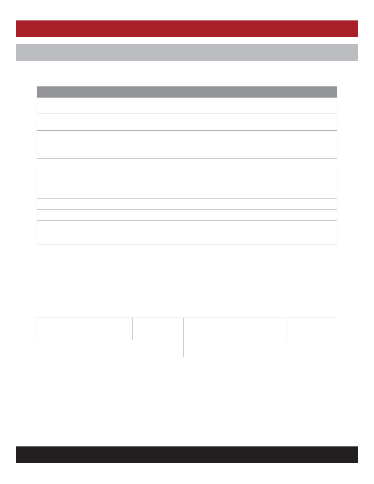
Number of beeps 1 2 3 4 5
Radio link quality
NOT RECOMMENDED
Risk of system failure
Recommended installation
CHANNEL SAFETY SYSTEMS t: 0845 884 7000 | w: www.channelsafety.co.uk
INSTRUCTION MANUAL - Issue 1 - 02/2014 | 4
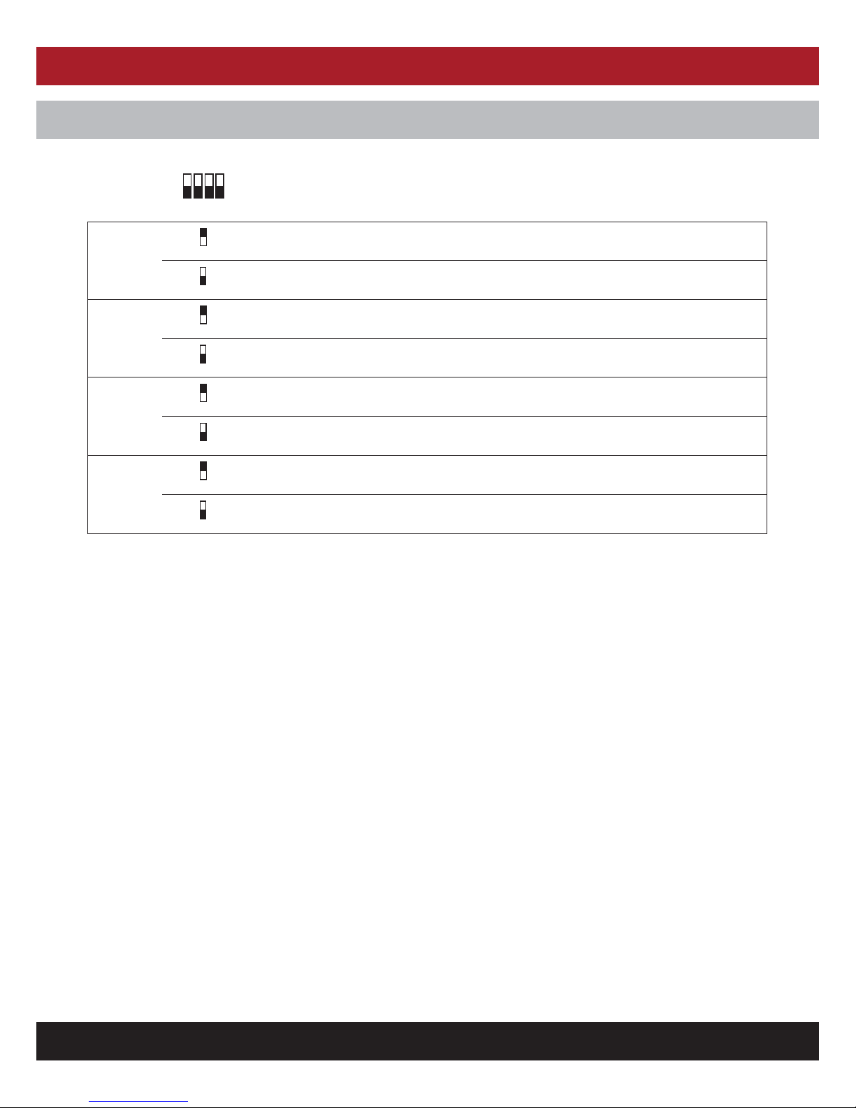
SWITCH CONFIGURATION
Default setting:
12
34
ON
OFF
Switch 1
ON
1
Auxiliary input closing
OFF
1
Auxiliary input opening
Switch 2
ON
2
«Type 4» alarm > sound on the stand alone alarms, no alarm on the smoke detector
OFF
2
«smoke detector» alarm > intermittent sound on the stand alone alarms and activated smoke
detector
Switch 3
ON
3
No activation of the alarm relay when receiving a smoke detector alarm.
OFF
3
Activation of the alarm relay when receveing smoke detector alarm messages.
Switch 4
ON
4
No activation of the alarm relay when receiving a stand alone or manual call point alarm.
OFF
4
Activation of the alarm relay when receveing stand alone alarm or manual call point alarm messages.

CHANNEL SAFETY SYSTEMS t: 0845 884 7000 | w: www.channelsafety.co.uk
INSTRUCTION MANUAL - Issue 1 - 02/2014 | 5
USE
Test
Regularly perform this test on all the connected smoke detectors. This test can’t be carried out on the connected manual call points or stand alone alarms.
2. All smoke detectors test
The all smoke detectors TEST function allows to check at any time the radio link quality between all the connected smoke detectors and the radio link alarm
interface module.
→ Press the interface module key (short press).
→ Test is activated for all the connected smoke detectors. A sound signal indicates that the radio signal is being sent.
Note : this function is inhibited in case of alarm.
→ Alarm signal
The interface module receives alarm information from connected smoke detectors, manual call points and stand alone
alarms.
When an alarm information is sent, the interface module red indicator is steady on.
20 seconds after the original alarm has disappeared, the interface module is automatically reset.
Test Signal Note
For 1 minute Beeps + red blinking indicator The number of beeps and blinking correspond to the radio link quality of
the last received signal.
Then for 4 minutes Red blinking indicator
→ To stop the TEST signal before the end of the test, press the interface module key.
1. One smoke detector test
The one smoke detector TEST function allows to check at any time the radio link quality between one smoke detector and the radio link alarm interface
module.
→ Press the TEST key of a connected smoke detector.
→ The TEST signal is sent to the interface module (for 5 minutes).

CHANNEL SAFETY SYSTEMS t: 0845 884 7000 | w: www.channelsafety.co.uk
INSTRUCTION MANUAL - Issue 1 - 02/2014 | 6
VISUAL AND SOUND IDENTIFICATION
Visual identi cation Meaning Note
Blue indicator radio activity -
Red indicator steady on alarm signal received -
blinking test signal received the number of blinking correspond to the radio link quality of
the last received signal.
Sound identi cation Meaning Note
1 to 5 beeps sequences for 1 minute test signal received the number of beeps correspond to the radio link quality of the last
received signal
Sequences from 1 to 5 beeps every few seconds connection in process
CHANNEL SAFETY SYSTEMS t: 0845 884 7000 | w: www.channelsafety.co.uk
INSTRUCTION MANUAL - Issue 1 - 02/2014 | 7
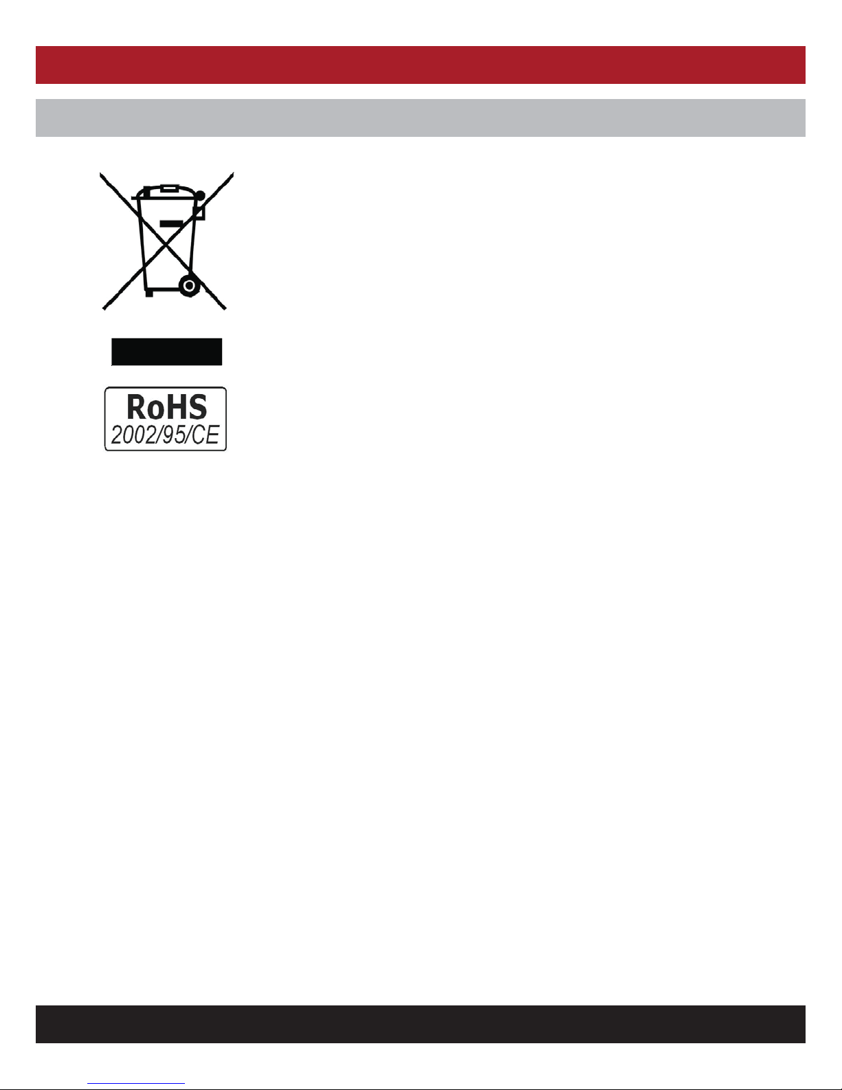
ENVIRONMENTAL PROTECTION
2002/96/EC (WEEE directive): Products marked with this symbol cannot be disposed of as unsorted munici pal
waste in the European Union.
For proper recycling, return this product to your local supplier upon the purchase of equivalent new equipment,
or dispose of it at designated collection points.
This product complies to the RoHS 202/95/EC relating to the restriction of the use of certain hazardous substances in electrical and electronical equipment since July 1st, 2006

INSTRUCTION MANUAL
CHANNEL SAFETY SYSTEMS t: 0845 884 7000
Peters eld Business Park f: 0845 884 6000
Bedford Road
Peters eld
Hampshire e: sales@channelsafety.co.uk
GU32 3QA w: www.channelsafety.co.uk
 Loading...