

Page 1
5115 Modulator Series
Model 5115HHR
Model 5115BID
Model 5115PAL
714-996-4100 * 800-999-5225 * fax 714-996-4900 * www.channelplus.com
600-132 Rev.A ©1999 Multiplex Technology, Inc., Brea, Ca.
PERFORMANCE MULTI-ROOM VIDEO
Multiplex Technology, Inc. warrants this product to be
free from defects in materials and workmanship for a
period of one year from the date of purchase or MTI will
repair, or at its option, replace the defective product. To
obtain warranty service, call MTI for a return material
authorization (RMA) number and return the product prepaid to Multiplex Technology, Inc., 3001 Enterprise
Street, Brea, CA 92821, Attention: Customer Service.
Please put the RMA number on the outside of the carton.
Any implied warranty arising from the sale of the product including implied warranties of merchantability and
fitness for purpose are limited to the warranty stated
above. MTI shall not be responsible for losses or damages or expenses, whether direct, consequential or incidental arising from the use of or the inability to use this
product. Some states do not allow limitations on how
long the implied warranty lasts or the exclusions or limitations or incidental or consequential damages, so the
above limitations and exclusions may not apply to you.
This warranty gives you specific legal rights, and you
may have other rights which may vary from state to
state.
WARRANTY
Page 2
The 5115 series is a audio/video distribution system that creates a
new channel to add to existing television channels. The new channel
carries audio/video from any video source to all the TVs in the home
The 5115 was designed to install effortlessly into existing coax home
wiring or into new construction.
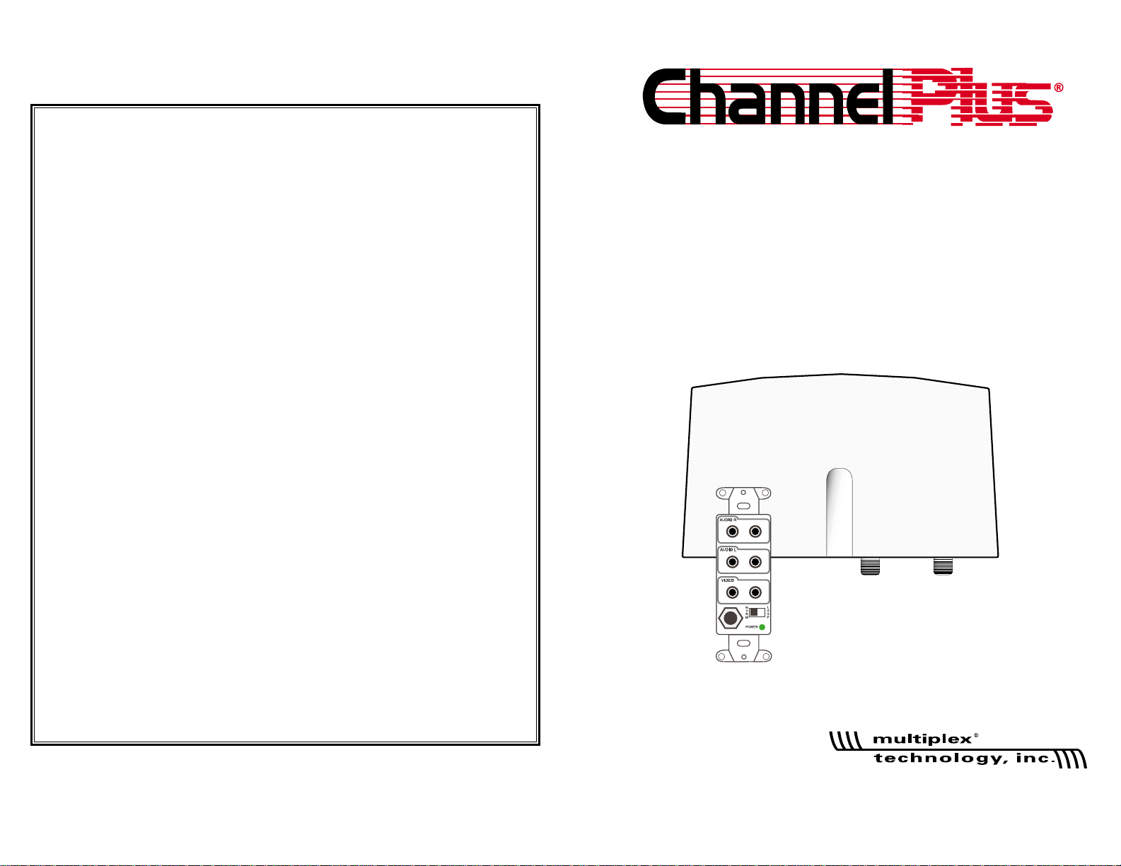
Contents: Channel Injector
Wall plate
Power Injector
Power Supply
Coax Jumper
The 5115 series is comprised of a wall plate and a channel injector.
The channel injector is weather resistant and designed to mount
indoors or outdoors close to the incoming CATV or antenna feed.
The system uses the existing coax cable distribution in the house
and only requires a single run of Cat 5.
The 5115 was designed to work with Cat 5 wiring. Although the system will function with quad wire, Cat 5 delivers the highest quality
picture. The Cat 5 allows the use of an automatic line length sensor
and picture compensator. Quad wire does not take advantage of
this enhancement.
Model Differences:
The model 5115HHR is a high headroom design for CATV and off
air antenna feeds only.
The model 5115BID is a bi-directional design for use with CATV
cable boxes that are interactive or require bi-directional
communications with the cable company.
The model 5115PAL is designed to modulate PAL frequencies and
use CATV or off air antenna feeds.
Installation:
First, locate the incoming CATV or antenna feed and install the
channel injector at that location.
Second, install the wall plate at the desired location and run Cat 5
wire from the wall plate to the channel location. Then connect a
video source.
Third, apply power and select an unused channel for the 5115
picture to appear on all the televisions.
2
Installation
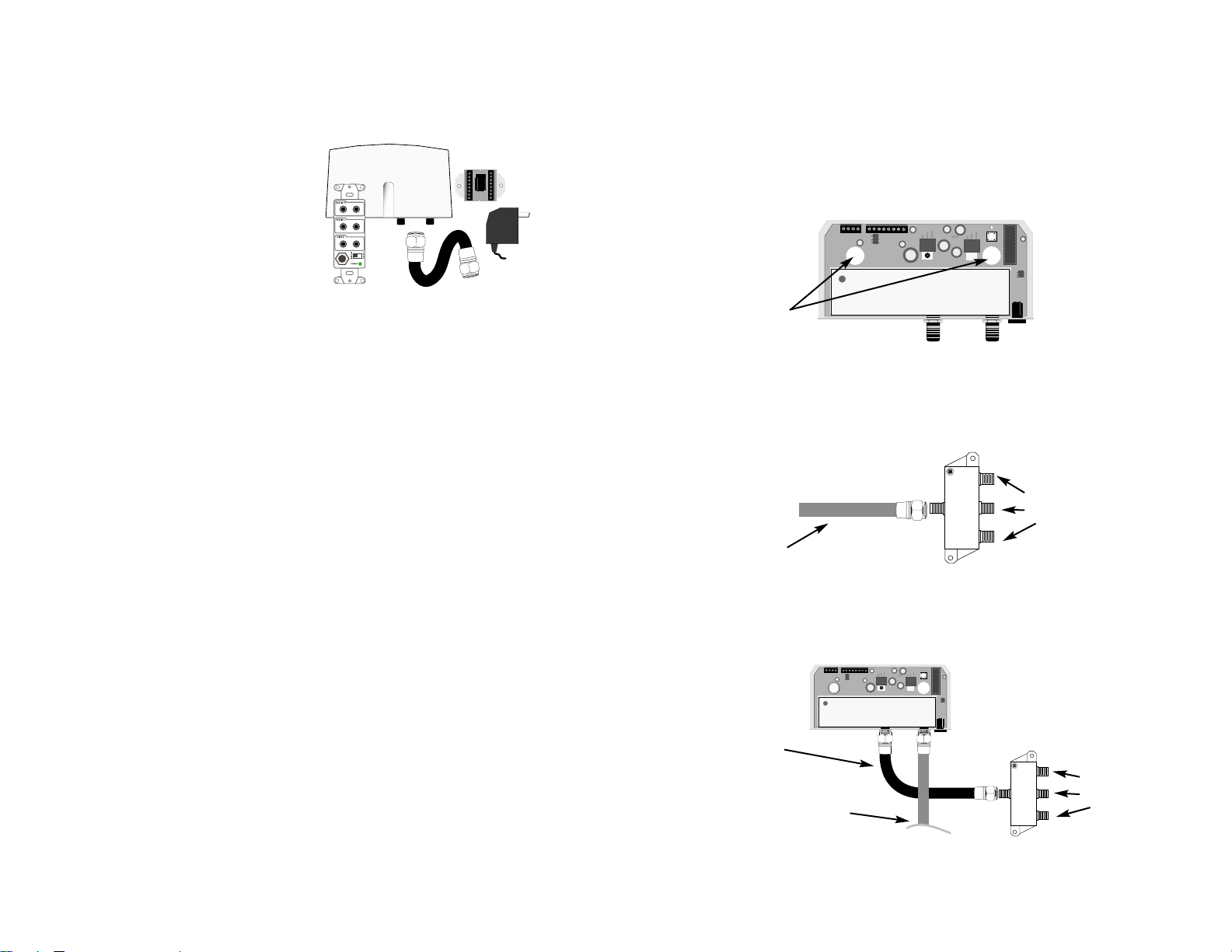
Step One
Locate the incoming CATV or antenna feed and existing splitter.
(Usually found on the side of the house, in the attic or near the electrical and phone service box)
Remove the lock screw located on the bottom of the channel
injector and slide the cover off. Use the mounting holes as shown to
affix the channel injector to the wall next to the splitter.
Disconnect the incoming CATV or antenna feed from the existing
splitter and attach it to the channel injector as shown.
Now attach the supplied coax jumper back to the existing splitter
and tighten all connections with a 7/16” wrench.
Use mounting
holes on the
bottom plate to
attach channel
injector to the
wall
Incoming CATV or
antenna coax
Out
to TVs
3
Incoming CATV or
antenna coax
Supplied coax
jumper goes back
to splitter
Out
to TVs
After
Before
Mount the
injector within
4” of the splitter
Mount the
injector within
4” of the splitter
© 1999
© 1999
Page 3

Connecting A Video Source
Using any video source, DVD,Satellite or VCR connect it to the wall
plate as shown. This video source will be transmitted over the Cat 5
wire to the channel injector.
Use the NORM / LOOP switch to select the proper setting for your
application.
NORM:
Select NORM when a television or a/v receiver is not used at the wall
plate to view the connected source.
LOOP:
Select LOOP when a television or a/v receiver is connected to the
wall plate to view the connected source
5
© 1999
Audio/video
connections
Cat 5 wire
Coax jumper
Out to
TVs
Optional loop
out television
or a/v receiver
Antenna or
CATV feed
Video source
Norm/Loop
switch
*
*
Installation of the wall plate
Step Two
The wall plate mounts using a low voltage ring into a wall cut out.
Run a line of Cat 5 wire from the wall plate to the channel injector
and connect wires as shown.
note:
When using quad wire connect
wires only to pins 1, 2, 5 and 6.
Leave the resistor in place
at pins 3 and 4.
At the channel injector, connect Cat 5 wire as shown. Follow the
color coding on the screw terminal.
Bl/W
Blue
Org/W
Orange
Gr/W
Green
Br/W
Brown
Green
Red
Black
Yellow
pin
1
2
3
4
5
6
7
8
4
Default
resistor
pin
1
2
5
6
note:
When using Cat 5 wire
remove the default resistor
that is in pins 3 and 4 of the
wall plate screw terminal
Side view
of wall plate
blue/white
pin 1
When using only quad wire
use positions 1, 2, 5 and 6
and follow color coding.
run the Cat 5 wire
through the grommet at the
bottom of the injector
blue/white
pin 1
© 1999
Page 4

Method Two: Use the power injector to apply power along the Cat
5 or quad wire run. Cut the connecting wire along the run and insert
the power injector. Connect the wires using the color coding. Then
plug the power supply into the power injector.
The green LED in the upper right corner of the channel injector will
be lit showing power is active.
Method Three: Apply power directly at the wall plate.
7
Applying Power and Programming
Step Three
The 5115 series has three different methods for applying power
to the system.
Use only one method for applying power.
Method One: Apply power directly to the channel injector with the
power supply.
The green LED in the upper right corner of the injector will be lit
showing power is active.
(See power length requirements page 8)
6
Power plug
Lower right of
channel injector
© 1999
power supply
power injector
pin 1
blue/white
cut Cat 5 wire
power plug
The green LED in the lower
right corner of the wall plate
and upper right corner of the
channel injector will be lit
showing power is active.
power supply
power plug
Page 5

How to Program
Determine which unused channel you want to view your video
source on and program the injector for that channel. There must be
one unused channel both before and after the selected channel to
avoid interference. The new channel will be combined with the existing channels and appear on all televisions.
To program: For example channel 60
1: Press the button 6 times.
2: Wait for the LED to relight.
3: Press the button 10 more times (pressing 10 times enters “0”).
The injector will now combine the wall plate feed on channel 60 with all other
existing channels from the incoming CATV or antenna.
To program a three digit channel: For example channel 120
1: Press the button 1 time.
2: Wait for the LED to relight.
3: Press the button 2 more times.
4: Wait for the LED to relight.
5: Press the button 10 more times.
Finding Unused Channels
CATV: Determine the highest channel number delivering a picture,
excluding 95-99. Tune the TV up one channel at a time from the last
channel with a picture until finding one channel with no trace of a
picture or interference, just snow.
Antenna: Tune the TV one channel at a time from channel 14-64.
Locate one channel that has no trace of a picture or interference,
just snow.
9
green LED
programming button
Upper right corner on
channel injector
© 1999
Power Length Requirements
Method One
Power Length Requirements
Method Two
Power Length Requirements
Method Three
8
power plug
Up to 300’ of
Cat 5 or quad
wire maximum
power plug
power plug
Up to 300’ of
Cat 5 or quad
wire maximum
Up to 100’ of
Cat 5 or quad
wire maximum
Up to 100’ of
Cat 5 or quad
wire maximum
Page 6

Programming a New Channel
Valid channels are 14 thru 64 for UHF and 65 thru 125 for CATV
Channels 95-99 are not available. Channels 21 thru 62 are for Pal.
Channel Spacing:
Skip at least one number between the new channel and the closest
existing UHF/CATV channel.
(example 14 and 16: OK 14 and 15: Unacceptable)
Error Indication:
If an error occurs or an incorrect channel is entered, the LED will
flash quickly for one second and return to previous settings.
Cable HRC and IRC considerations:
Most cable services use IRC frequency assignments. This is the
default for the 5115. However, if the cable services uses HRC or
the TV appears to search for the “created channel”, program the
channel injector for HRC.
For HRC enter 98. Reset to IRC by entering 99.
Entries 98 and 99 are for setting HRC or IRC only. They will not
change the channel number.
With programming complete, test each TV in the system to see that it is
receiving the new channel.
10
Specifications: typical @ 25°C ± 5° C
5115HHR / 5115BID 5115PAL(AUS)
video input format NTSC CCIR
input signal 1.0 V peak-to-peak @ 75Ω
output 12dBmV normal - 15.5dBmV maximum
input connectors 3 RCA (video + audio left + audio right)
loop-thru connectors 3 RCA (video + audio left + audio right)
video termination 75Ω or > 1 MΩ in “loop” position (selectable)
tuning range UHF 14 to 64 21 to 62(28 to 67)
CATV 65 to 125
A
power supply included with product
mains power 105 to 125 210 to 250
output of power supply 15VDC 600mA
general
width x height x depth injector module wall plate
6.5” x 3.5” x 1.25” 1.25” x 4.0” x 1.75”
(16.3cm x 9cm x 3.2cm) (3.2 cm x 10.5cm x 4.0cm)
shipping weight 2 lbs (0.9 kg)
operating temperature –4°F to 131°F (–20°C to 55°C)
A
excluding channels 95 through 99
11
 Loading...