

Page 1
PERFORMANCE MULTI-ROOM VIDEO
Coaxial Cable Panel
Instruction Manual
®
For use with model
2100A IR wallplates
INPUT
Ant /
CATV
+15Vdc
Gnd
IR Out
MODULATORS
A B+Pwr
INPUTS
model 3308 Coax Panel
OUTPUTS
To
TVs
®
Model 3308
multiplex
technology, inc.
3001 Enterprise Street, Brea, CA 92821-6213, U.S.A.
714-996-4100 * 800-999-5225 * FAX 714-996-4900 * www.channelplus.com
R
Page 2
Model 3308
Model 3308
Power Supply
Power Supply
(included)
(included)
Top View
Top View
+15Vdc
+15Vdc
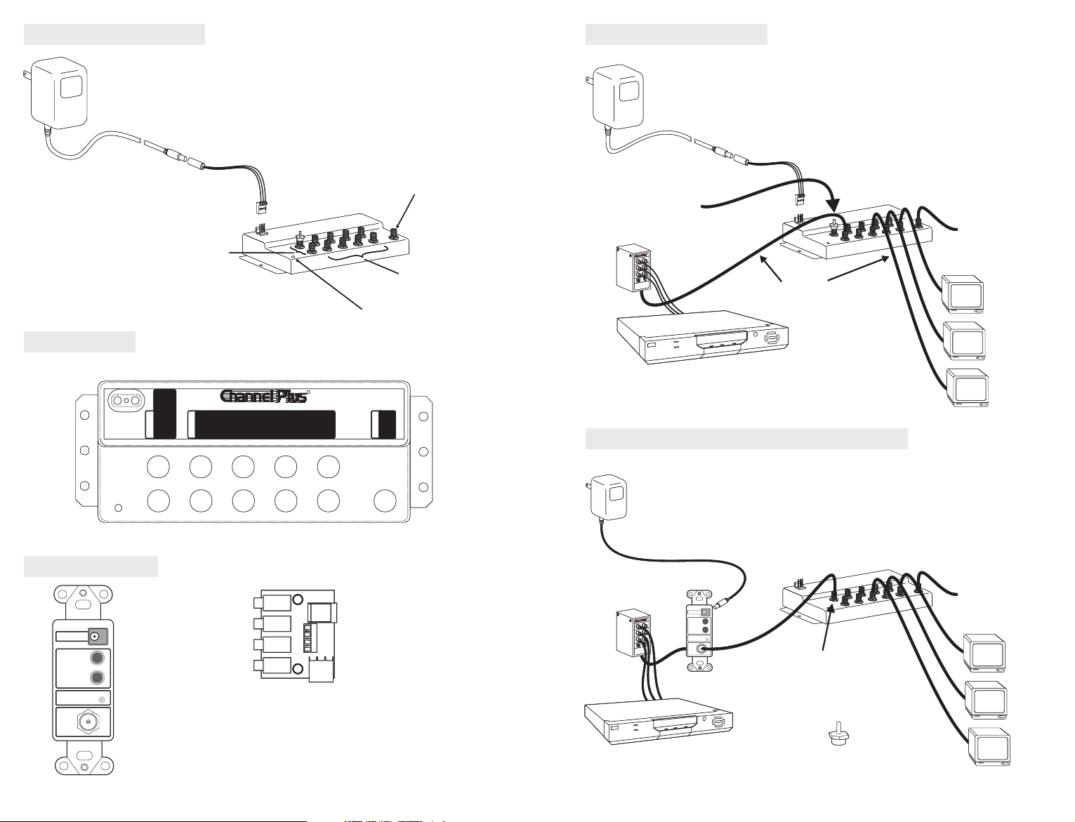
The 3308 Coaxial Cable Panel is the heart of a multi-
The 3308 Coaxial Cable Panel is the heart of a multiroom video distribution system. The 3308 connects as
room video distribution system. The 3308 connects as
many as 8 televisions to cable or antenna, while
many as 8 televisions to cable or antenna, while
maintaining compatibility with ChannelPlus video
maintaining compatibility with ChannelPlus video
modulators and the ChannelPlus bi-directional IR
modulators and the ChannelPlus bi-directional IR
repeating system.
repeating system.
Modulator inputs
Modulator inputs
(2)
(2)
Gnd
Gnd
IR Out
IR Out
MODULATORS
MODULATORS
A B+Pwr
A B+Pwr
INPUTS
INPUTS
OUTPUTS
OUTPUTS
Power Supply
Power Supply
Adaptor
Adaptor
(included)
(included)
model 3308 Coax Panel
model 3308 Coax Panel
To
TVs
To
TVs
R
R
Antenna/CATV
Antenna/CATV
Power LED
Power LED
For use with model
For use with model
2100A IR wallplates
2100A IR wallplates
INPUT
INPUT
TV outputs
TV outputs
Ant /
Ant /
CATV
CATV
(8)
(8)
Typical System
Typical System
LOSS-LESS COAX PANEL
LOSS-LESS COAX PANEL
The model 3308 works like a zero-loss splitter! The
The model 3308 works like a zero-loss splitter! The
signals you put on the antenna/CATV input will
signals you put on the antenna/CATV input will
appear on the outputs at the same power.
appear on the outputs at the same power.
Modulators may be connected
Modulators may be connected
to the ‘A’ or ‘B’ ports.
to the ‘A’ or ‘B’ ports.
Modulator
Modulator
R
R
Shielded 75 ohm coax is
Shielded 75 ohm coax is
required. We recommend RG-6.
required. We recommend RG-6.
Satellite receiver
Satellite receiver
Remote Power Using the Model 2010
Remote Power Using the Model 2010
Up to 8 TVs
Up to 8 TVs
Antenna/CATV
Antenna/CATV
Accessories
Accessories
VIDEO SYSTEM
VIDEO SYSTEM
POWER
POWER
15VDC
15VDC
IR
IR
EMITTERS
EMITTERS
Model 2010
SYSTEM POWER
SYSTEM POWER
FROM
FROM
MODULATOR
MODULATOR
Model 2010
Power Injector wall plate
Power Injector wall plate
(fits standard Decora)
(fits standard Decora)
+12
+12
GND
GND
-
-
LED
LED
+
+
Replaces the power supply
Replaces the power supply
adaptor and drives up
adaptor and drives up
to four IR emitters.
to four IR emitters.
2
2
Model 2184
Model 2184
IR Breakout
IR Breakout
Model 2010
Model 2010
Power Injector
Power Injector
Modulator
Modulator
R
R
Satellite receiver
Satellite receiver
VIDEOSYSTEM
VIDEOSYSTEM
POWER
POWER
15VDC
15VDC
IR
IR
EMITTERS
EMITTERS
SYSTEMPOWER
SYSTEMPOWER
FROM
FROM
MODULATOR
MODULATOR
FREEDOM OF PLACEMENT
FREEDOM OF PLACEMENT
Put the 3308 coax panel where the coax is: in the
Put the 3308 coax panel where the coax is: in the
attic, in the basement or in the wall of the garage.
attic, in the basement or in the wall of the garage.
The single coax from a model 2010 carries power,
The single coax from a model 2010 carries power,
the RF signals and IR repeating signals.
the RF signals and IR repeating signals.
Antenna/CATV
Antenna/CATV
Up to 8 TVs
Up to 8 TVs
IMPORTANT:
IMPORTANT:
The model 2010 must connect to
The model 2010 must connect to
Modulator B +Pwr
Modulator B +Pwr
the port. If the
the port. If the
2010 is not being used, then
2010 is not being used, then
install a 75 ohm terminator here.
install a 75 ohm terminator here.
3
3
Page 3

IR Repeating System
IR Repeating System
With the model 3308,you can also controlyour video devices fromany
With the model 3308,you can also controlyour video devices fromany
room in the house. Any or all 8 outputs may be connected to model
room in the house. Any or all 8 outputs may be connected to model
2100A wall plates. The wall plates interface with a variety of industry
2100A wall plates. The wall plates interface with a variety of industry
standard IR targets. Direct your IR remote control at the IR target and
standard IR targets. Direct your IR remote control at the IR target and
the 2173 IR emitter will repeat the IR signals inthe media center.
the 2173 IR emitter will repeat the IR signals inthe media center.
Model 2132
Model 2132
Compatible IR Targets
Compatible IR Targets
Model 2171 IR Emitter
Model 2131
Model 2131
Normally, the IR emitters are also connected to Model 2100A wall
Normally, the IR emitters are also connected to Model 2100A wall
plates. But, if the coax panel is located in the media center, you may
plates. But, if the coax panel is located in the media center, you may
choose to connect the emitters to a model 2184 IR breakout panel.
choose to connect the emitters to a model 2184 IR breakout panel.
Both examples are shown below. The model 2184 plugs directly into
Both examples are shown below. The model 2184 plugs directly into
the 3308, replacing the power adaptor cable. The 2184 can drive up to
the 3308, replacing the power adaptor cable. The 2184 can drive up to
4 IR emitters.
4 IR emitters.
Model 2184
Model 2184
Model 2130A
Model 2130A
Model 2173
Model 2173
Model 2100A
Model 2100A
TARGET
TARGET
LED
LED
LED
LED
EMITTER
EMITTER
EMITTER
EMITTER
POWER
POWER
TOTVTO
TOTVTO
TV
TV
Model 2171 IR Emitter
Model 2173
Model 2173
2
2
Are repeated at the media
Are repeated at the media
center. Change the DSS
center. Change the DSS
channel or pause the
channel or pause the
VCR from any room.
VCR from any room.
If the coax panel is not located at the media center, you may add a
If the coax panel is not located at the media center, you may add a
model 2010 remote power wall plate at the media center and connect
model 2010 remote power wall plate at the media center and connect
the 3308 and 2010 with asingle coax cable. The model 2010 will power
the 3308 and 2010 with asingle coax cable. The model 2010 will power
the 3308, drivethe IR emitters and deliver any modulator signals to the
the 3308, drivethe IR emitters and deliver any modulator signals to the
3308. In addition, the 2010 has connectors for 2 IR emitters. (The
3308. In addition, the 2010 has connectors for 2 IR emitters. (The
model 2174 IR expansion panel will expand each of these ports to
model 2174 IR expansion panel will expand each of these ports to
drive up to 4 IR emitters.)
drive up to 4 IR emitters.)
2
2
Model 2010
Model 2010
VIDEOSYSTEM
The 2010 must be
The 2010 must be
powered as shown.
powered as shown.
Modulators may
Modulators may
be connected here.
be connected here.
Model 2010 MUST be
Model 2010 MUST be
connected to the ‘B’ port.
connected to the ‘B’ port.
More modulators may be
More modulators may be
connected to the ‘A’ port.
connected to the ‘A’ port.
VIDEOSYSTEM
POWER
POWER
15VDC
15VDC
IR
IR
EMITTERS
EMITTERS
SYSTEMPOWER
SYSTEMPOWER
FROM
FROM
MODULATOR
MODULATOR
Model 2173
Model 2173
When using IR repeating,
When using IR repeating,
only a or
only a or
may be directly connected
may be directly connected
to a 3308 output.
to a 3308 output.
Max recommended
Max recommended
cable length 150’ (Total
cable length 150’ (Total
of these two pieces.)
of these two pieces.)
Are repeated at
Are repeated at
the media
the media
2100A DC block
2100A DC block
DC block
DC block
Model 2130A
Model 2130A
1
1
IR control signals
IR control signals
from the bedroom …
from the bedroom …
TARGET
TARGET
LED
LED
LED
LED
EMITTER
EMITTER
EMITTER
EMITTER
POWER
POWER
TOTVTO
TOTVTO
TV
TV
Model 2100A
Model 2100A
4
4
IR targets must be connected
IR targets must be connected
to a model 2100A wall plate.
to a model 2100A wall plate.
Model 2132
Model 2132
1
1
IR control signals
IR control signals
from the bedroom …
from the bedroom …
TARGET
TARGET
LED
LED
LED
LED
EMITTER
EMITTER
EMITTER
EMITTER
POWER
POWER
TOTVTO
TOTVTO
TV
TV
Model 2100A
Model 2100A
5
5
IR targets must be connected
IR targets must be connected
to a model 2100A wall plate.
to a model 2100A wall plate.
Page 4

Expanding the 3308:
Expanding the 3308:
CATV/Ant
CATV/Ant
Model 3308
Model 3308
Up to 64 TV outlets
Up to 64 TV outlets
You may connect up to 8 more
You may connect up to 8 more
3308s to the outputs of a ‘master’
3308s to the outputs of a ‘master’
3308, for a total of 64 TV outlets.
3308, for a total of 64 TV outlets.
The longest recommended coax
The longest recommended coax
run is 150 feet (includes coax from
run is 150 feet (includes coax from
master to secondary unit and from
master to secondary unit and from
secondary unit to TV).
secondary unit to TV).
Mounting the 3308
Mounting the 3308
The model3308 should be mountedin a location thatis safe and dry. The model 3308 is
The model3308 should be mountedin a location thatis safe and dry. The model 3308 is
small enough to be mounted a stud wall. Alternatively, the 3308 may be mounted
small enough to be mounted a stud wall. Alternatively, the 3308 may be mounted
inside a ChannelPlus Integrated Home Network enclosure.
inside a ChannelPlus Integrated Home Network enclosure.
inside
inside
Model 3308 Model 3308
Model 3308 Model 3308
All 3308s must be powered individually.
All 3308s must be powered individually.
Each 3308 can have its’ own ‘zoned’ IR control and local modulators.
Each 3308 can have its’ own ‘zoned’ IR control and local modulators.
(Modulators connected to a secondary 3308 will be viewable only on
(Modulators connected to a secondary 3308 will be viewable only on
those 8 TVs. IR control signals will be confined to only that 3308.)
those 8 TVs. IR control signals will be confined to only that 3308.)
Circuit Breaker
Circuit Breaker
The model 2010 and 3308 have built-in circuit breakers. If any of these LEDs are not
The model 2010 and 3308 have built-in circuit breakers. If any of these LEDs are not
lit, reset the circuit breaker by disconnecting and reconnecting the power supply. If
lit, reset the circuit breaker by disconnecting and reconnecting the power supply. If
the system does not reset, look for an installation error.
the system does not reset, look for an installation error.
Model 2010
Model 2010
Power Injector
Power Injector
VIDEOSYSTEM
VIDEOSYSTEM
POWER
POWER
15VDC
15VDC
IR
IR
EMITTERS
EMITTERS
SYSTEMPOWER
SYSTEMPOWER
FROM
FROM
MODULATOR
MODULATOR
Power LED
Power LED
Note: The model 2010
Note: The model 2010
must connect to
must connect to
this port.
this port.
Model 2600
Model 2600
(surface mount)
(surface mount)
Things to watch for:
Things to watch for:
Herringbone interference on modulator channel (diagonal lines)
Herringbone interference on modulator channel (diagonal lines)
You may have chosen a channel number that is not completely vacant. Distant UHF stations
You may have chosen a channel number that is not completely vacant. Distant UHF stations
may notbe watchable, but willcause interference if youtry to try tocreate a new channelat the
may notbe watchable, but willcause interference if youtry to try tocreate a new channelat the
same frequency. Also, cable companies often have extrasignals where there should benone.
same frequency. Also, cable companies often have extrasignals where there should benone.
Try moving the modulatorchannel to another number. You may have to add a low pass filter to
Try moving the modulatorchannel to another number. You may have to add a low pass filter to
remove cable company noise. If a filter does not work, try adding a DC-block to remove
remove cable company noise. If a filter does not work, try adding a DC-block to remove
common mode interference.
common mode interference.
Herringbone interference on many channels, including modulator
Herringbone interference on many channels, including modulator
channels (disappears when you remove the CATV/Ant feed)
channels (disappears when you remove the CATV/Ant feed)
overloaded by abnormally strong signals. Often, you can cure the problem with a simple
overloaded by abnormally strong signals. Often, you can cure the problem with a simple
attenuator. Use a variable attenuator and try to find a signal level where the interference just
attenuator. Use a variable attenuator and try to find a signal level where the interference just
disappears. Sometimes, the problem is one station that is far stronger than the rest. In this
disappears. Sometimes, the problem is one station that is far stronger than the rest. In this
case, attenuating allof the signals with a simple attenuator will cause the desiredstations to be
case, attenuating allof the signals with a simple attenuator will cause the desiredstations to be
weak (snowy). You must reduce the strength of only the offending station. A common FM trap
weak (snowy). You must reduce the strength of only the offending station. A common FM trap
will help if the problem is a nearby FM tower. If the problem is a nearby TV station, often the
will help if the problem is a nearby FM tower. If the problem is a nearby TV station, often the
station management can provide suitable filters.
station management can provide suitable filters.
Infrared Remote Control Problems … The most common cause of IR problems are:
Infrared Remote Control Problems … The most common cause of IR problems are:
IR emitter not located directly above sensor on the video device. Reposition the IR emitter
IR emitter not located directly above sensor on the video device. Reposition the IR emitter
TV is radiating electrical noise. Reposition IR target.
TV is radiating electrical noise. Reposition IR target.
IR target is ‘seeing’ optical noise, such as a solid state flourescent lamp. Reposition IR target.
IR target is ‘seeing’ optical noise, such as a solid state flourescent lamp. Reposition IR target.
NOTE:
NOTE:
Model 2601
Model 2601
(surface mount)
(surface mount)
Model 2603
Model 2603
(in-wall mount)
(in-wall mount)
Shown with
Shown with
model 2613 cover
model 2613 cover
… The RF amplifier can be
… The RF amplifier can be
...
...
Remember, connecting
Remember, connecting
75 ohm terminators
75 ohm terminators
directly to the outputs is
directly to the outputs is
not necessary and will
not necessary and will
cause the circuit breaker
cause the circuit breaker
to trip.
to trip.
Power LED
Power LED
6
6
Power LED
Power LED
We recommend using only RG-6 coax when wiring a house. Why? Although good RG-59 has
We recommend using only RG-6 coax when wiring a house. Why? Although good RG-59 has
only slightly more loss than RG-6, it is harder to find good RG-59. RG-6 is a little more
only slightly more loss than RG-6, it is harder to find good RG-59. RG-6 is a little more
expensive and a little harder to run (because it is thicker). But you will avoid surprises if you
expensive and a little harder to run (because it is thicker). But you will avoid surprises if you
stick to RG-6.
TARGET
TARGET
LED
LED
LED
LED
EMITTER
EMITTER
EMITTER
EMITTER
POWER
POWER
TOTVTO
TOTVTO
TV
TV
stick to RG-6.
Inexpensive DC block for RFInexpensive variable attenuator
7
7
Inexpensive DC block for RFInexpensive variable attenuator
Page 5

Specifications: typical @ 25 C ± 5 C
Gain: Antenna/CATV port to output: 0dB
Modulator input to output -10dB
Ant isolation (Modulator input to CATV/Ant): >80dB
Modulator input: +25dBmV (+85dBuV)
Bandwidth: 50-806MHz
Max CATV/Antenna input: 20dBmV (+80dBuV)
Power 15 VDC @ 250 mA
Power supply (included): 350-076
OO
Dimensions: 6.3“ x 0.9” x 2.5“
Shipping weight: 4 lbs.(1.8kg)
16cm x 2.35cm x 6.35cm
Warranty
Multiplex Technology, Inc. warrants this product to be free
from defects in materials and workmanship for a period of
one year from the date of purchase or MTI will repair, or at
its option, replace the defective product. To obtain
warranty service, call MTI for a return material
authorization (RMA) number and return the product
prepaid to Multiplex Technology, Inc., 3001 Enterprise
Street, Brea, CA 92821, Attention: Customer Service.
Please put the RMA number on the outside of the carton.
Any implied warranty arising from the sale of the product
including implied warranties of merchantability and fitness
for purpose are limited to the warranty stated above. MTI
shall not be responsible for losses or damages or
expenses, whether direct, consequential or incidental
arising from the use of or the inability to use this product.
Some states do not allow limitations on how long the
implied warranty lasts or the exclusion or limitation or
incidental or consequential damages, so the above
limitations and exclusions may not apply to you. This
warranty gives you specific legal rights, and you may have
other rights which may vary from state to state.
600-077 Rev. E600-077 Rev. E
 Loading...