

Channel Master 2016, 2018, 2020, Digital Advantage 2016, Digital Advantage 2018 Installation Instructions Manual
...
DIGITAL
ADVANTAGE
MEDIUM AND LONG RANGE TV ANTENNAS
HD DIGITAL / UHF / VHF HIGH
45-60
Models
INSTALLATION INSTRUCTIONS
60
35
2016, 2018
INSTALLATION INSTRUCTIONS
DIGITAL
ADVANTAGE
MEDIUM AND LONG RANGE TV ANTENNAS
HD DIGITAL / UHF / VHF HIGH
and 2020
HIGH-DEFINITION TELEVISION
2020
Best for
LONG RANGE
2018
Best for
LONG RANGE
Up to
60
Miles
Up to
45-60
Miles
2016
Best for
MEDIUM RANGE
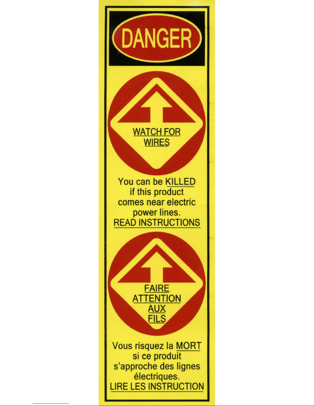
WARNING: Installation of this product near
power lines is DANGEROUS! For your safety, read
the enclosed “DANGER” booklet before beginning
your installation.
Up to
35
Miles
www.channelmaster.com

INSTALLATION TIPS
A. USEFUL INSTALLATION TOOLS
• Large and small blade screwdrivers
• Adjustable Wrench
• Wire Cutters
• Pliers
B. WHERE TO MOUNT YOUR
ANTENNA
Your antenna can be mounted on either the
chimney, the root or on an outside wall or in an
attic. Choose the method that best suits your
particular location.
its base, down to a 8’ ground rod. Keep the Iine at
a respectable distance from your transmission wire
to prevent signal interference. A coaxial grounding
block (Channel Master Model 3274), should be
connected to the antenna transmission wire at the
point where it enters the house.
E. AIMING YOUR ANTENNA TOWARD
THE TRANSMITTING STATION
Once the antenna installation is completed, turn your
TV set on and have an assistant observe the reception.
On the roof, Ioosen the U-bolt nuts and turn the
antenna until you get the best reception. Once this
is accomplished, tighten U-bolts nuts securely,
C. TRANSMISSION LINE
75 Ohm coaxial cable has a Ionger Iife-span than
300 Ohm twinlead cable and is unaffected by
contact with metal or moisture. To install coaxial
cable, begin by connecting the antenna end of the
cable to the antenna balun (supplied with antenna).
Attach the input wires of the balun to the antenna
terminals, Next, run the coaxial cable through a
standout mounted on the mast. This will prevent
the weight of the Iine from pulling on the antenna
connections.
D. LIGHTNING PROTECTION
The mast and transmission Iine should be grounded
for Iightning protection. Run a #8 (or larger),
aluminum or copper wire from a bolt on the mast or
NOTE: If broadcast stations are in different
directions, you will need an antenna rotator.
This will allow you to rotate
pinpoint individual stations from inside your home.
(For more information on rotators, visit www.
channelmaster.com.)
Find the installation you plan to make on the
following pages - READ THE INSTRUCTIONS
FOR ASSEMBLING THE ANTENNA AND THE
INSTALLATION BEFORE YOU START THE
ACTUAL WORK!
Visit your local retailer or our website for available
mounts and accessories you’ll need for your
installation.
From this point, the rest of the coax may be taped
to the mast.
the antenna and
1

INSTALLATION LOCATIONS
ATTIC MOUNT
ROOF MOUNT
(Using Guy Wire)
CHIMNEY MOUNT WALL MOUNT TRIPOD
IMPORTANT SAFEGUARDS
• Remember, when working on a roof, use two adults.
• Never walk on a composition roof in cold weather.
• Wear sneakers or crepe soles, and use a safety rope.
• Always watch for power lines.
A. ATTIC MOUNT
Using a roof mount, attach a short piece of mast to a
convenient roof rafter. Attach and aim the antenna in
the same manner as outlined for outdoor installations.
NOTE: Antennas should not be installed in an attic if the
roof or walls are metal or are lined with foil backed insulation.
B. ROOF MOUNT
Used on peaked or fl at roofs.
Suggested Height Limit: 10 feet above roof top.
Using a roof mount, connect the mast with guy ring and
guy wires attached, to the mount. Use three or four guy
wires, equally spaced around the mast, and anchor
the guy wires to the roof or eaves with eyebolts. The
guy ring should be clamped approximately one (1) foot
below the antenna, Use roofi ng compound around the
base of the mount, screws and eyebolts to seal against
moisture. After the installation has been completed,
mount the extra WARNING LABEL supplied with the
antenna hardware to the mast at EYE LEVEL!
C. CHIMNEY MOUNTING
Suggested Height Limit: 10 feet above rooftop.
First, check your chimney thoroughly for stability
to make sure that it is strong enough to support the
antenna during severe winds. Do not use a chimney
that has loose bricks or mortar. Install the upper bracket
just below the top course of bricks and the lower bracket
at least 2 1/2 feet below the top bracket. (For maximum
strength, space the brackets as far apart as possible.)
After the installation has been completed, mount the
extra WARNING LABEL supplied with the antenna
hardware to the mast at EYE LEVEL!
D. WALL MOUNT
Suggested Height Limit: 10 feet above rooftop.
If the roof overhang is not excessive, the side of the
house can be used for mounting. If a wall mounted
installation is done from the ground up, use a ground
mount with a “spike” at the ground. Position the wall
brackets over a stud if possible; one above the other
and space a minimum of three feet (3) apart. For metal
siding, mark mounting holes, then drill pilot holes through
the siding for mounting screws. If you use a 2-piece
mast, assemble the pieces as shown, making sure that
they are properly locked together. Split between masts
should be between the two (2) wall brackets, After
the installation has been completed, mount the extra
WARNING LABEL supplied with the antenna hardware
to the mast at EYE LEVEL!
E. TRIPOD MOUNT
Use on peaked or fl at roofs.
Suggested Height Limit: 10 feet above roof top.
The tripod mount can be mounted to any style roof by
adjusting the bracket on the center leg. Insert the mast
into the tripod mount and place the mount with legs over
the roof rafters. Make sure the mast is vertical. Remove
the protective covering from one side of the three (3)
pitch pads and place under the base of each tripod leg
with the tacky side towards the roof. Secure the tripod
mount to the roof using lag screws. After the installation
has been completed, mount the extra WARNING LABEL
supplied with the antenna hardware to the mast at
EYE LEVEL!
F. ANTENNA REMOVAL
Removal of your antenna should be exactly in reverse
of the installation instructions. For your own safety,
please follow the instructions for installing the antenna
starting with the last step fi rst. This is the only way to
safely remove your antenna.
2

ANTENNA ASSEMBLY
1. Carefully unfold the antenna elements and
snap them into place. (See Figs. 1 & 2)
2. For Models 2018 & 2020: Connect the
antenna sections together. (See Fig. 3)
3. Using the provided wing nuts, attach the rods
that are riveted to the rear section to the studs
above the dipole on the front section.
Model 2016: Connect as shown in Fig. 6.
Models 2018 & 2020: Attach the matching
transformer to the screw terminals not
used to attach the connection rods.
(See Figs. 4 & 5)
4. Mount the antenna to the pole. (See Figs. 7 & 8)
Model 2020: This model has 2 sets of hardware.
5. To align the antenna, point the narrow end of
the antenna towards the transmitter location
and adjust for best picture quality or signal
strength.
Fig. 1
Fig. 2
Fig. 3
Fig. 4 Fig. 5
Fig. 6
Fig. 7 Fig. 8
Models 2018 & 2020 - Top of AntennaModels 2018 & 2020 - Bottom of Antenna
All rights reserved.
1.866.430.1307 | 1.919.934.7078 | techsupport@channelmaster.com
Specifi cations subject to change.
3
www.channelmaster.com
©2009 Channel Master. Tempe AZ USA.
Pub CM.INST.2016_2018_2020.20090420

 Loading...