


DIGITAL
ADVANTAGE
antenna series
™
USER GUIDE
GUÍA PARA
EL USUARIO
CM-2016 CM-2018 CM-2020
MODE
D’EMPLOI

This page intentionally left blank.

Table of Contents
Product Overview ....................................................................3
Package Contents and Accessories .....................................3
Danger Information .................................................................4
Installation Tips ..........................................................................6
Installation Locations ...............................................................8
Antenna Assembly .................................................................11
Operating Instructions ...........................................................12
Technical Data .......................................................................13
Product Return Policy and Warranty ................................... 14
Índice
Perspectiva General del Producto ......................................16
Contenido del Paquete y Accesorios .................................16
Información Sobre Peligros ................................................... 17
Consejos Para La Instalación ................................................19
Lugares De Instalación ..........................................................21
Montaje De Antena .............................................................. 24
Instrucciones de Operación .................................................25
Datos Técnicos ....................................................................... 26
Garantía y Póliza para la Devolución del Producto..........26
Index
Présentation du Produit .........................................................29
Contenu et Accessoires de L'emballage............................29
Conseils de Sécurité ...............................................................30
Conseils D'Installation ............................................................32
Les Sites D'installation ............................................................ 34
Assemblage De L'Antenne ...................................................37
Mode D'emploi ....................................................................... 40
Données Techniques ............................................................. 41
Politique de Reprise de Marchandise et Garantie ............ 41
1

CM-2016
Medium Range Antenna
Antena de Medio Alcanc
Antenne de Moyenne portée
HD
MILE
45
Alcance de recepción
Rayon de captage
RANGE
72 KM
CM-2018
CM-2020
2
Long Range Antenna
Antena de Largo Alcance
Antenne Longue Portée
HD
60
Alcance de recepción
Rayon de captage
Long Range Antenna
Antena de Largo Alcance
Antenne Longue Portée
96 KM
HD
100
Alcance de recepción
Rayon de captage
DIG I TAL A DVAN T AGE
160 KM
ant e nna s erie s
MILE
RANGE
MILE
RANGE
™
Product Overview
All Channel Master Digital Advantage Series Outdoor
Antennas are engineered to be easy to install, and
have been optimized for receiving high band VHF, UHF,
and HDTV signals. Attention to detail has been taken into
consideration; every piece is smooth and machined to
ensure a safe, trouble-free installation.
Every antenna is made of the nest components to
exceed consumer expectations. That means peace of
mind for years to come.
Product Features
• Optimum reception for digital broadcasts
• Easy installation - Unfold, mount, and connect
• Economical
• Long lasting, durable design:
- Spun boom ends reduce wind whistle
- Reinforced element sleeves for added strength
• Easily mounts to a traditional antenna mast
• Rooftop, eave, or wall mountable
Package Contents and Accessories
All Digital Advantage™ antennas include:
• Hardware
• User Guide
• Danger Label
• 75 Ohm matching transformer
• Coaxial Cable and Mast not included
3
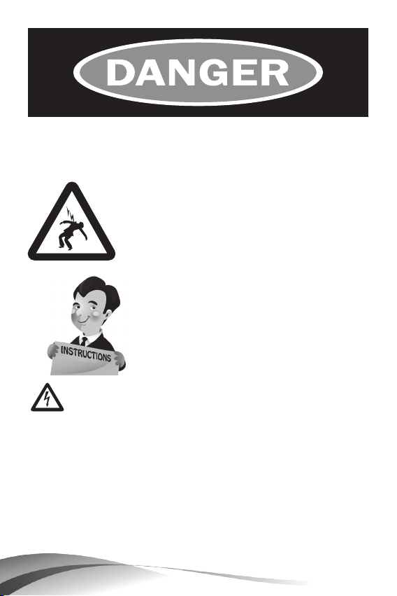
WATCH FOR WIRES!
You can be KILLED if
this antenna comes near
electric power lines!
READ INSTRUCTIONS
WARNING AND SAFETY
Please read this user's manual before operating this
product. The information contained in this document
is subject to change without notice. Features or
specications may be different depending on the type
of product model purchased.
INFORMATION
4
DIG I TAL A DVAN T AGE
ant e nna s erie s
™

Follow These Procedures for the
Safest Installation
1. Perform as much antenna assembly on the ground as
possible.
2. Watch out for overhead power lines. Check the
distance to the power lines before you start installing.
WE RECOMMEND YOU STAY A MINIMUM OF TWICE THE
MAXIMUM LENGTH OF THE ANTENNA ASSEMBLY AWAY
FROM ALL POWER LINES.
3. Do not use a metal ladder.
4. Remember, even the slightest touch of an antenna to a
power line can cause a fatal shock.
5. Do NOT try to do the job on a windy day.
6. Have a friend as a spotter when you’re on the roof.
They can see things you can’t.
7. If you start to drop an antenna, move away from it and
let it fall.
8. If any part of the antenna should come into contact
with a power line CALL YOUR LOCAL POWER COMPANY!
DO NOT TRY TO REMOVE IT YOURSELF! They will remove it
safely.
9. Mast, lead-in, and metal guy wires are excellent
conductors of electrical current - - keep them away
from power lines too.
10. Be sure your family and friends understand the danger
of touching an overhead power line. Tell them never to
try to remove any object in contact with a power line
(TV antenna, mast or anything else).
11. Make sure that the antenna mast assembly is properly
grounded.
For more information, visit
www.channelmaster.com/support.
5

Installation Tips
A. USEFUL INSTALLATION TOOLS
• Large and small blade screwdrivers
• Adjustable Wrench
• Wire Cutters
• Pliers
B. WHERE TO MOUNT YOUR ANTENNA
Your antenna can be mounted on either the chimney,
the root or on an outside wall or in an attic. Choose the
method that best suits your particular location.
C. TRANSMISSION LINE
75 Ohm coaxial cable has a Ionger Iife-span than 300
Ohm twinlead cable and is unaffected by contact
with metal or moisture. To install coaxial cable, begin
by connecting the antenna end of the cable to the
antenna balun (supplied with antenna). Attach the
input wires of the balun to the antenna terminals, Next,
run the coaxial cable through a standout mounted on
the mast. This will prevent the weight of the Iine from
pulling on the antenna connections.
D. LIGHTNING PROTECTION
The mast and transmission Iine should be grounded for
Iightning protection. Run a #8 (or larger), aluminum or
copper wire from a bolt on the mast or its base, down
to a 8’ ground rod. Keep the Iine at a respectable
distance from your transmission wire to prevent signal
interference. A coaxial grounding block (Channel
Master Model 3274), should be connected to the
antenna transmission wire at the point where it enters
the house.
6
DIG I TAL A DVAN T AGE
ant e nna s erie s
™

“S” Clamp
Balun
75 Ohm Coaxial Cable
Spade Lugs
(Connect to VHF Terminals on TV Set)
75 OHM SEPARATOR
*For older TV sets only
Wire Lugs (Connect to UHF
Terminals on TV Set)
E. AIMING TOWARD A TRANSMITTING STATION
Once the antenna installation is completed, turn your
TV set on and have an assistant observe the reception.
On the roof, Ioosen the U-bolt nuts and turn the
antenna until you get the best reception. Once this is
accomplished, tighten U-bolts nuts securely,
NOTE: If broadcast stations are in different directions,
you will need an antenna rotator.
This will allow you to rotate the antenna and pinpoint
individual stations from inside your home. (For more
information on rotators, visit www.channelmaster.com.)
Find the installation you plan to make on the following
pages.
**READ THE INSTRUCTIONS FOR ASSEMBLING THE
ANTENNA AND THE INSTALLATION BEFORE YOU START THE
ACTUAL WORK!**
Visit your local retailer or our website for available
mounts and accessories you’ll need for your installation.
7
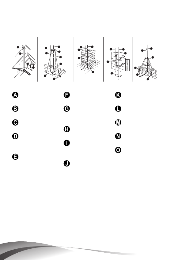
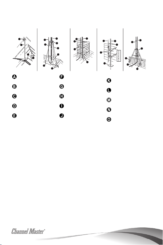
Installation Locations
A
A
D
D
D
J
E
F
G
H
I
K
L
B
B
B
B
C
C
C
C
D
E
M
N
O
B
C
ATTIC
MOUNT
ROOF
MOUNT
(Using Guy Wire)
CHIMNEY
MOUNT
WALL
MOUNT TRIPOD
RoofMount
GuyWire
GroundMount
Mast
GuyRing&
WallMount
Clamp
CoaxialCable
TripodMount
Eyebolts
Snap-On
Standouts
ChimneyMount
Straps
PitchPads
LagScrews
Screw-In
Standouts
ChimneyMount
Important Safeguards
• Remember, when working on a roof, use two adults.
• Never walk on a composition roof in cold weather.
• Wear sneakers or crepe soles, and use a safety rope.
• Always watch for power lines.
8
DIG I TAL A DVAN T AGE
ant e nna s erie s
™

A. ATTIC MOUNT
Using a roof mount, attach a short piece of mast to a
convenient roof rafter. Attach and aim the antenna in
the same manner as outlined for outdoor installations.
NOTES: Antennas should not be installed in an attic if
the roof or walls are metal or are lined with foil backed
insulation.
B. ROOF MOUNT
Used on peaked or at roofs.
Suggested Height Limit: 10 feet above roof top.
Using a roof mount, connect the mast with guy ring
and guy wires attached, to the mount. Use three
or four guy wires, equally spaced around the mast,
and anchor the guy wires to the roof or eaves
with eyebolts. The guy ring should be clamped
approximately one (1) foot below the antenna, Use
roong compound around the base of the mount,
screws and eyebolts to seal against moisture. After
the installation has been completed, mount the extra
WARNING LABEL supplied with the antenna hardware
to the mast at EYE LEVEL!
C. CHIMNEY MOUNTING
Suggested Height Limit: 10 feet above rooftop.
First, check your chimney thoroughly for stability to
make sure that it is strong enough to support the
antenna during severe winds. Do not use a chimney
that has loose bricks or mortar. Install the upper
bracket just below the top course of bricks and
the lower bracket at least 2 1/2 feet below the top
bracket. (For maximum strength, space the brackets
as far apart as possible.) After the installation has been
completed, mount the extra WARNING LABEL supplied
with the antenna hardware to the mast at EYE LEVEL!
9

D. WALL MOUNT
Suggested Height Limit: 10 feet above rooftop.
If the roof overhang is not excessive, the side of the
house can be used for mounting. If a wall mounted
installation is done from the ground up, use a ground
mount with a “spike” at the ground. Position the wall
brackets over a stud if possible; one above the other
and space a minimum of three feet (3) apart. For
metal siding, mark mounting holes, then drill pilot holes
through the siding for mounting screws. If you use a
2-piece mast, assemble the pieces as shown, making
sure that they are properly locked together. Split
between masts should be between the two (2) wall
brackets, After the installation has been completed,
mount the extra WARNING LABEL supplied with the
antenna hardware to the mast at EYE LEVEL!
E. TRIPOD MOUNT
Use on peaked or at roofs.
Suggested Height Limit: 10 feet above roof top.
The tripod mount can be mounted to any style roof
by adjusting the bracket on the center leg. Insert
the mast into the tripod mount and place the mount
with legs over the roof rafters. Make sure the mast is
vertical. Remove the protective covering from one
side of the three (3) pitch pads and place under the
base of each tripod leg with the tacky side towards
the roof. Secure the tripod mount to the roof using
lag screws. After the installation has been completed,
mount the extra WARNING LABEL supplied with the
antenna hardware to the mast at EYE LEVEL!
F. ANTENNA REMOVAL
Removal of your antenna should be exactly in reverse
of the installation instructions. For your own safety,
please follow the instructions for installing the antenna
starting with the last step rst. This is the only way to
safely remove your antenna.
10
DIG I TAL A DVAN T AGE
ant e nna s erie s
™
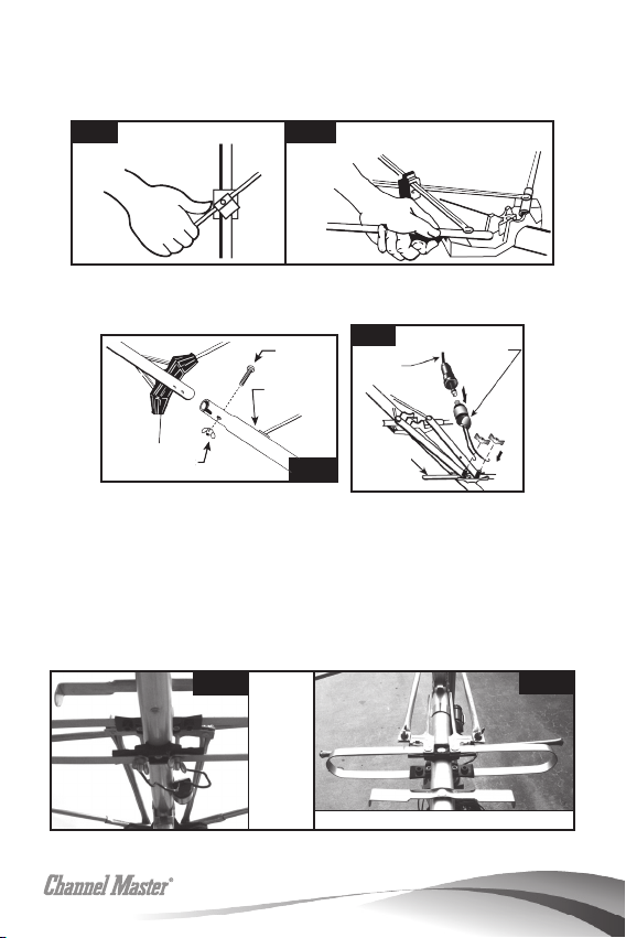
Antenna Assembly
Models 2018
& 2020 -
Bottom of
Antenna
Fig 4
Models
2018 &
2020 -
Bottom of
Antenna
Fig 1 Fig 2
Fig 4
Fig 1 Fig 2
Fig 3
Screw
Crossarm
Wing Nut
Coaxial
Cable
Straight
UHF Dipole
1. Carefully unfold the antenna elements and snap them
into place. (See Figs. 1 & 2)
Fig 1 Fig 2
2. For Models CM-2018 & 2020: Connect the antenna
sections together. (See Fig. 3)
Screw
Crossarm
Fig 4
Coaxial
Cable
Matching
Transformer
Wing Nut
3. Using the provided wing nuts, attach the rods that
are riveted to the rear section to the studs above the
Fig 3
Straight
UHF Dipole
dipole on the front section.
Model CM-2016: Connect as shown in Fig. 4.
Models CM-2018 & 2020: Attach the matching
transformer to the screw terminals not used to attach
the connection rods. (See Figs. 5 & 6)
Fig 5
Models
2018 &
2020 Bottom
of
Antenna
Models 2018 & 2020 - Top of Antenna
Fig 6
11
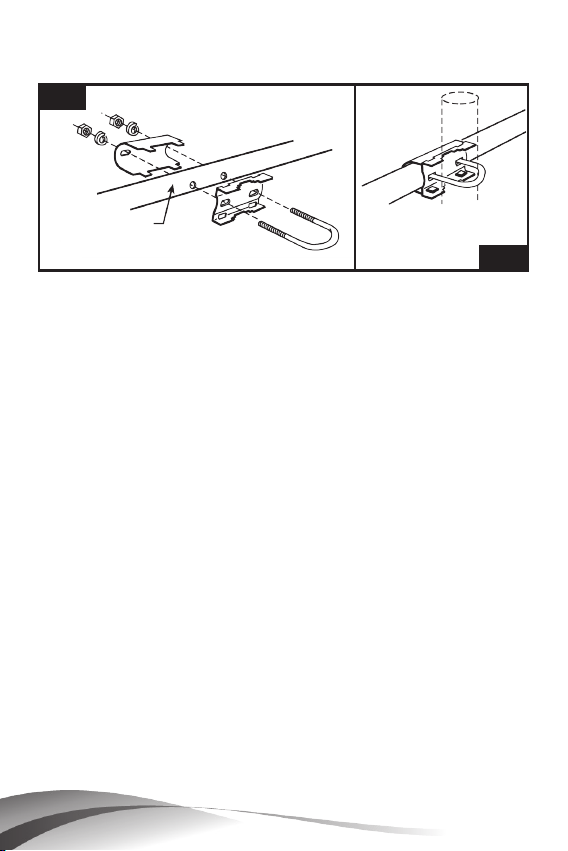
4. Mount the antenna to the pole. (See Figs. 7 & 8) Model
Models 2018 & 2020 - Top of Antenna
Fig 6
Straight
UHF Dipole
CM-2020: This model has 2 sets of hardware.
Fig 7
Antenna Crossarm
Fig 8
5. To align the antenna, point the narrow end of the
antenna towards the transmitter location and adjust for
best picture quality or signal strength.
Operating Instructions:
For best reception, please consider the following
conditions:
1. Keep the antenna away from sources of interference,
including air conditioners, microwave ovens, hair
dryers, etc. These are all sources of strong electrical
interference, and can cause poor quality or total loss of
TV signals.
2. Install the antenna as high as possible, and preferably
with a clear path between the antenna and the TV
station transmitters. Trees, buildings, mountains, etc.,
can all impact the performance of any antenna.
12
DIG I TAL A DVAN T AGE
ant e nna s erie s
™

Features and Technical Data for
the Digital Advantage Antenna Series
• Designed for reception of HD digital TV signals
• Frequency Range: 174-216, 470-700 MHz
• Impedance: 75Ω
• Gain:
CM-2016
Average Gain:
VHF: 2.0 dB
UHF: 7.5 dB
Number of Elements: 22
CM-2020
Average Gain:
VHF: 7.7 dB
UHF: 9.4 dB
Number of Elements: 41
CM-2018
Average Gain:
VHF: 7.5 dB
UHF: 8.2 dB
Number of Elements: 24
13

Product Return Policy and Warranty
WARRANTY PERIOD: 90-day warranty applies to all Channel Master Products (Some
products have extended term warranty periods). DEALERS & CONSUMERS: Dealers and
consumers can return any In-Warranty Channel Master product to the Warranty department
for repair or replacement. For In-Warranty service the consumer or dealer must call Technical
Service and request an RMA number in order to return the product. The returned product
must have the RMA number visible on the box and must include the bill of sale showing
the unit is within the warranty period. If the unit is found to be defective under our Warranty
Policy Channel Master will repair or replace the item at no charge. Products outside of
the warranty period should not be returned to Channel Master with the exception of any
product requested by Technical Support to be assessed for quality assurance purposes.
Technical Service: www.channelmaster.com/support
WARRANTY GENERAL TERMS: 1.1 Subject to the provisions of this Warranty, CHANNEL
MASTER warrants that the equipment and software described in Paragraph 1.2 will conform
to our specications in all material respect and that the equipment will be free from material
defects in materials and workmanship during the Limited Warranty period. 1.2 This Warranty
applies to all original purchases by Customers of CHANNEL MASTER (“Equipment”).The
warranties set forth herein are not transferable. 1.3 The Effective period of this Warranty
will start on the date of purchase of the Equipment or the date of installation by a CHANNEL
MASTER approved technician and will end, for the Equipment, ninety (90) days later (for all
component parts and system upgrades), unless otherwise expressed or provided herein (in
each case the “Warranty Period”).
RETURN OF EQUIPMENT UNDER WARRANTY: 2.1 If an item of Equipment malfunctions
or fails in normal use within the applicable Warranty Period: (a) the Customer shall notify
CHANNEL MASTER within thirty (30) days of the problem. (b) CHANNEL MASTER will,
at its option, either resolve the problem over the telephone or provide the customer with a
Return Authorization (“RMA”) Number and the address to which the customer may ship the
defective item; (c) If the problem can not be resolved over the telephone, the Customer shall
attach a label showing the RMA number to each returned item, and include a description
of the problem. The Customer shall, at his or her own cost, properly pack the item to be
returned, mark the RMA# on the outside of the box, prepay the insurance and shipping
charges, and ship the item to the specied CHANNEL MASTER location. (d) Unauthorized
return of any equipment, whether in or out of warranty, will be subject to a handling charge, in
addition to all repair and all transportation charges. (e) CHANNEL MASTER will, at its sole
option, repair or replace the returned item. If replaced, the replacement item may be new or
refurbished; if refurbished it will be equivalent in operation to new Equipment. If a returned
item is replaced by CHANNEL MASTER, the Customer agrees that the returned item will
become the property of CHANNEL MASTER. (f) CHANNEL MASTER will complete the
exchange of CHANNEL MASTER manufactured equipment returned under this Warranty
within a reasonable time, subject to lead-times from factory, and will make a good faith effort
to minimize any and all delays where possible; and (g) CHANNEL MASTER will, at its cost,
ship the repaired item or replacement to the Customer. If the Customer requests express
shipping, the Customer will pay CHANNEL MASTER an expediting fee. 2.2 Equipment
which is repaired or replaced by CHANNEL MASTER under this Warranty will be covered
under all of the provisions of this Warranty for the remainder of the applicable Warranty
period (for that particular equipment) from the date of repair or replacement, whichever is
longer. 2.3 If equipment is repaired beyond effective warranty dates or if abnormal usage
had occurred, Customer shall be charged applicable rates and the Customer will be advised
of the estimated charges prior to repair by CHANNEL MASTER ‘s authorized service center.
14
DIG I TAL A DVAN T AGE
ant e nna s erie s
™

2.4 The price of out-of-warranty repairs payable by the Customer will be based on standard
labor and parts prices in effect at the time of the repair. CHANNEL MASTER will use its best
efforts to ensure that the cost of such repair, exchange, refurbishing, or substitution will not
exceed the original price of Product. 2.5 If the problem reoccurs within the warranty period,
CHANNEL MASTER will, at its option: (1) re-perform the service; (2) replace the product
pursuant to the terms of this warranty, (3) permit Customer to return the product and issue a
refund pursuant to this warranty, or (4) refund the amount the Customer paid for the services.
PRODUCT MODIFICATION: 3.1 CHANNEL MASTER reserves the right to make changes or
improvements to its products, during subsequent production, without incurring the obligation
to install such changes or improvements on previously manufactured or sold products.
FORCE MAJEURE: 4.1 CHANNEL MASTER will not be liable if its performance under this
warranty becomes commercially impracticable due to any contingency beyond CHANNEL
MASTER’s reasonable control, including acts of God, res, ood, wars, sabotage, civil
unrest, accidents, labor disputes or shortages, government laws, rules and regulations,
whether valid or invalid, inability to obtain material, equipment or transportation, incorrect,
delayed or incomplete specications, drawings or data supplied by Customer (collectively
“Force Majeure”)
LIMITATIONS AND QUALIFICATIONS OF WARRANTY: 5.1 This Limited Warranty
extends only to the original purchaser of the Equipment and is in lieu of all other express or
implied warranties, including those of merchantability and tness for a particular purpose.
This Warranty does not apply to any damage, defect of failure caused by: (a) any part of the
equipment having been modied, adapted, repaired, maintained, transported or relocated
by any person; (b) Storage or environmental characteristics which do not conform to the
applicable sections of the appropriate Equipment Manual or Instruction Sheet; (c) Failure
to conform with the Equipment Operating Instructions in the applicable Equipment Manual
or Instruction Sheet; (d) External causes, including external electrical stress or lightning,
or use in conjunction with incompatible equipment, unless such use was with CHANNEL
MASTER’s prior written request; (e) Cosmetic damage; (f) Accidental damage, negligence,
modication, mishandling, abuse or misuse; or (g) Force Majeure.
LIMITATION ON DAMAGES: 6.1 THIS WARRANTY IS THE CUSTOMER’S EXCLUSIVE
WARRANTY FOR THE EQUIPMENT, CHANNEL MASTER SPECIFICALLY DISCLAIMS
ALL OTHER WARRANTIES OF ANY KIND, EXPRESS OR IMPLIED, INCLUDING ANY
WARRANTIES OF FITNESS FOR A PARTICULAR PURPOSE AND OF MERCHANTABILITY.
6.2 CHANNEL MASTER WILL NOT BE LIABLE IN TORT, INCLUDING LIABILITY IN
NEGLIGENCE OR STRICT LIABILITY, AND WILL HAVE NO LIABILITY AT ALL FOR
INJURY TO PERSONS OR PROPERTY. CHANNEL MASTER’S LIABILITY FOR FAILURE
TO FULFILL ITS OBLIGATIONS UNDER THIS WARRANTY OR ANY OTHER LIABILITY
UNDER OR IN CONNECTION WITH THE EQUIPMENT WILL BE LIMITED TO THE
AMOUNT OF THE PURCHASE PRICE OF THE EQUIPMENT AT THE TIME OF ORIGINAL
PURCHASE. THE REMEDIES STATED IN THIS WARRANTY ARE THE CUSTOMER’S
EXCLUSIVE REMEDIES AGAINST CHANNEL MASTER REGARDING THE EQUIPMENT.
6.3 EVEN IF CHANNEL MASTER HAS BEEN NOTIFIED OF THE POSSIBILITY OF THEM,
CHANNEL MASTER WILL NOT BE LIABLE FOR ANY INDIRECT, INCIDENTAL, SPECIAL
OR CONSEQUENTIAL DAMAGES, INCLUDING LOST PROFITS AND REVENUES,
FAILURE TO REALIZE EXPECTED SAVINGS, ANY CLAIM AGAINST A CUSTOMER BY A
THIRD PARTY, OR ANY OTHER COMMERCIAL OR ECONOMIC LOSSES OF ANY KIND.
6.4 THESE LIMITATIONS AND DISCLAIMERS ARE NOT MADE BY CHANNEL MASTER
WHERE PROHIBITED BY LAW.
15

Información General Sobre el Producto
Todos Channel Master Digitales Antenas serie Advantage
al aire libre están diseñadas para ser fáciles de instalar,
y se han optimizado para la recepción de banda alta
VHF, UHF, y las señales de televisión de alta denición. La
atención al detalle se ha tenido en consideración, cada
pieza es lisa y mecanizado para garantizar un ambiente
seguro y libre de problemas de instalación. Cada antena
está hecha de los mejores componentes para superar
las expectativas de los consumidores. Eso signica
tranquilidad para los próximos años.
Características del Producto
• Recepción óptima para las emisiones digitales
• Fácil instalación - Despliegue, montar y conectar
• Económico
• De larga duración, diseño duradero:
- Spun auge termina reducir silbido del viento
- Mangas reforzadas para mayor resistencia del
elemento
• Se monta fácilmente a un mástil de la antena
tradicional
• Azotea, alero, o en la pared
Contenido del Envase y Accesorios
Todas Digital Advantage ™ antenas incluyen:
• Ferretería
• Hoja con instrucciones
• Folleto de peligro
• Transformador que empareja de 75 Ohm
• Cable coaxial y mástil no incluidos
16
DIG I TAL A DVAN T AGE
ant e nna s erie s
™

ỊCUIDADO CON LOS CABLES!
ỊSi esta antena entra en
contacto con cables de alta
tensión puede
ocasionarle la MUERTE!
LEA LAS INSTRUCCIONS
¡Advertencia e información
de seguridad!
Por favor, lea este manual antes de poner en
funcionamiento este producto. La información
contenida en este documento está sujeta a cambios
sin previo aviso. Las características y especicaciones
pueden ser diferentes en dependencia del modelo del
producto adquirido.
Para la Instalacion mas Segura, Siga Estos
Procedimientos
1. Realice la mayor parte de las tareas de montaje de la
antena en el piso.
2. Cuídese de los cables aéreos de alta tensión. Verique
la distancia que lo separa de los cables de alta tensión
17

antes de iniciar la instalación LE RECOMENDAMOS
QUE SE MANTENGA A UNA DISTANCIA MINIMA DE LOS
CABLES DE ALTA TENSIÓN IGUAL AL DOBLE DEL LARGO
DEL CONJUNTO DE LA ANTENA.
3. No utilice una escalera metálica.
4. Recuerde que hasta el contacto más leve entre la
antena y los cables de alta tensión pueden provocar
un descargo mortal.
5. No intente realizar esta tarea en un día ventoso.
6. Cuente con la presencia de otra persona para que
lo observe mientras se encuentra en el techo. Esta
persona puede ver cosas que usted no ve.
7. Si la antena comienza a caerse, aléjese y déjela caer.
8. ¡Si cualquier parte de la antena entra en contacto
con un cable de alta tensión - - Comuníquese CON
SU Compañía LOCAL DE ELECTRICIDAD! ¡NO INTENTE
RETIRARLA USTED MISMO! Ellos la retirarán de manera
segura.
9. El mástil, los cables de acometida y los cables
metálicos de retenido son excelentes conductores de
la corriente eléctrica - manténgalos alejados de los
cables de alta tensión.
10. Asegúrese de que sus familiares y amigos comprendan
el peligro que implica tocar un cable aéreo de alta
tensión. Dígales que nunca intenten retirar ningún
objeto que se encuentre en contacto común cable
de alta tensión - - una antena de CB, de TV o cualquier
otro elemento.
11. Asegúrese de que el conjunto del mástil de la antena
cuente con una conexión a tierra adecuada.
Para obtener más información, visite
www.channelmaster.com/support.
18
DIG I TAL A DVAN T AGE
ant e nna s erie s
™

Consejos Para La Instalación
A. INSTALACIÓN DE HERRAMIENTAS ÚTILES
• Grandes y pequeños destornilladores cuchilla
• Llave ajustable
• Cortadores de cable
• Alicates
B. DONDE MONTAR LA ANTENA
La antena se puede montar en la chimenea o bien,
la raíz o en una pared exterior o en un ático. Elija el
método que mejor se adapte a su situación particular.
C. LÍNEA DE TRANSMISIÓN
75 Ohm cable coaxial tiene una vida Ionger-span de
300 Ohm twinlead cable y no se ve afectada por el
contacto con el metal o la humedad. Para instalar
el cable coaxial, empezar por conectar la antena
extremo del cable a la antena balun (suministrado
con la antena). Conecte la entrada de los cables a la
antena balun terminales, y, después, el cable coaxial
a través de un standout montado en el mástil. Esto
evitará que el peso de la Iine tirando de las conexiones
de la antena.
D. PROTECCIÓN CONTRA RAYOS
El mástil y la transmisión Iine debe Iightning a tierra para
protección. Ejecutar un # 8 (o mayor), de aluminio o
cobre de un perno en el mástil o de su base, hasta
un 8 ‘vara de tierra. Mantenga el Iine a un respetable
distancia del cable de transmisión de señal para evitar
interferencias. Un bloque de tierra coaxial (Channel
Master Modelo 3274), debe estar conectado a la
antena de transmisión de cable en el punto en que
entra en la casa.
19

Abrazadera en S
75 ohmios cable coaxial
Balun
75 OHM
SEPARADOR
* Para mayores
televisores sólo
Spade Terminales
(Conectar a los terminales
de VHF de TV)
Orejetas de alambre (Conectar
a los terminales de UHF de TV)
E. ENCAMINADA HACIA SU ANTENA TRANSMITE LA
ESTACIÓN
Una vez que la antena se haya completado la
instalación, encienda su televisor y tener un ayudante
observar la recepción. En el techo, el U-Ioosen tuercas
y pernos a su vez la antena hasta obtener la mejor
recepción. Una vez que esto se logra, apriete los
pernos en U nueces segura..
NOTA: i las emisoras se encuentran en distintas
direcciones, necesitará una antena de los rotadores.
Esto le permitirá girar la antena y estaciones aisladas
de identicar desde el interior de su hogar. (Para más
información sobre rotadores, visite
www.channelmaster.com.)
Encuentra la instalación va a hacer en las páginas
siguientes
¡LEA LAS INSTRUCCIONES DE MONTAJE DE LA ANTENA
Y LA INSTALACIÓN ANTES DE COMENZAR EL TRABAJO
REAL!
Visite a su distribuidor local o nuestro sitio web
disponible para monturas y accesorios que usted
necesita para su instalación.
20
DIG I TAL A DVAN T AGE
ant e nna s erie s
™
Lugares De Instalación
MONTAJE EN
ATICO
A
B
MonturaparaTecho
Mástil
CableCoaxial
GuíasaPresión
Guíasatornillables
D
C
MONTAJE
EN TECHOS
(Uso de Guaya de
Tensión)
B
C
G
D
F
A
H
E
MONTAJE EN
CHIMENEA
B
C
D
I
J
GuayadeSoporte
Anilloyabrazadera
Tuercasdeojo
AmarresdeMontaje
MonturaparaChime-
nea
MONTAJE EN
PARED
C
B
D
L
K
MonturaparaSuelo
MonturaparaPared
MonturadeTrípode
Adaptadores
Tirafondos
O
E
TRÍPODE
C
B
N
M
Importantes Medidas De Seguridad
• Recuerde, cuando trabaje en un techo, utilice dos
adultos.
• Nunca camine sobre un techo impermeabilizado
cuando hace frío.
• Use zapatillas o suelas de crepé, y utilice una cuerda
de seguridad.
• Siempre tenga cuidado con las líneas eléctricas.
A. MONTAJE EN ÁTICO
Usando un montaje para techo, adjunte un trozo
pequeño de mástil a una viga del techo. Conecte
y oriente la antena de la misma manera que se
recomienda en instalaciones al aire libre.
21

NOTAS: Las antenas no deben ser instaladas en un ático
si el techo o las paredes son de metal o están revestidas
con lámina de aislamiento respaldada.
B. MONTAJE EN TECHO
Utilizado techos planos o inclinados.
Altura Límite Sugerida: 10 pies sobre la azotea.
Usando una montura para techo, conecte el mástil con
los anillos y la guaya de soporte a la montura. Utilice tres
o cuatro guayas, separadas uniformemente alrededor
del mástil, y ánclelas en el techo o en los aleros usando
tuercas de ojo. El anillo de soporte debería sujetarse
alrededor de un (1) pie por debajo de la antena, Utilice
impermeabilizante para techos alrededor de la base
de la montura, tornillos y tuercas para sellar contra la
humedad. Después de completar la instalación, coloque
LA ETIQUETA DE ADVERTENCIA adicional suministrada con
el hardware de la antena en el mástil AL NIVEL DE LOS
OJOS!
C. MONTAJE EN CHIMENEA
Altura Límite Sugerida: 10 pies sobre la azotea.
En primer lugar, revise su chimenea fondo de estabilidad
para asegurarse de que es lo sucientemente fuerte
como para apoyar la antena durante vientos severos.
No use una chimenea que suelta los ladrillos o mortero.
Instale la parte superior del soporte justo por debajo de la
parte superior del curso inferior de los ladrillos y el soporte,
al menos, 2 1/2 pies por debajo de la abrazadera
superior. (Para conseguir la máxima fuerza,
el espacio entre paréntesis tan distantes como sea
posible.) Después de la instalación se ha completado,
monte LA ETIQUETA DE ADVERTENCIA adicional
suministrada con el hardware de la antena al mástil AL
NIVEL DE LOS OJOS!
22
DIG I TAL A DVAN T AGE
ant e nna s erie s
™

D. DE MONTAJE EN PARED
Altura Límite Sugerida: 10 pies sobre la azotea.
En primer lugar, revise la estabilidad de su chimenea
a fondo para asegurarse de que es lo sucientemente
fuerte como para sostener la antena durante vientos
severos. No use una chimenea que tenga ladrillos o
morteros sueltos. Instale el soporte superior justo por
debajo de la parte superior de la cara inferior de los
ladrillos, y el soporte inferior, al menos 2 1 / 2 pies por
debajo de la abrazadera superior. (Para conseguir la
máxima resistencia, separe tanto como sea posible
ambos soportes.) Después de completar la instalación,
monte LA ETIQUETA DE ADVERTENCIA adicional
suministrada con el hardware de la antena en el mástil
AL NIVEL DE LOS OJOS!
E. MONTURA PARA TRIPODE
Utilicela en techos planos o inclinados.
Altura Límite Sugerida: 10 pies sobre la azotea.
La montura para trípode se puede colocar en cualquier
estilo de techo ajustando el soporte de la pata central.
Introduzca el mástil en la montura para trípode y monte
la estructura con patas sobre las vigas del techo.
Asegúrese de que el mástil quede vertical. Quite la
cubierta protectora a un lado de cada uno de los tres
(3) adaptadores y coloque cada una de las patas de la
base del trípode con el lado pegajoso hacia el techo.
Asegure el trípode en el techo mediante tirafondos.
Después de completar la instalación, coloque LA
ETIQUETA DE ADVERTENCIA adicional suministrada con el
hardware de la antena en el mástil al NIVEL DE LOS OJOS!
F. DESMONTAJE DE LA ANTENA
El desmontaje de la antena debe ser efectuado
exactamente al contrario de las instrucciones de
instalación. Por su propia seguridad, por favor, siga las
instrucciones para la instalación de la antena a partir del
último paso en primer lugar. Esta es la única manera de
desmontar de forma segura la antena.
23

Montaje De Antena
Models 2018
& 2020 -
Bottom of
Antenna
Fig 4
Models
2018 &
2020 -
Bottom of
Antenna
Fig 1 Fig 2
Fig 4
Fig 1 Fig 2
Fig 3
Screw
Crossarm
Wing Nut
Coaxial
Cable
Straight
UHF Dipole
1. Cuidadosamente desplegar elementos de la antena y
ajustar en su lugar. (Ver Figs. 1 y 2)
Fig 1 Fig 2
2. Para los Modelos CM-2018 y 2020: conectar la antena
secciones juntos. (Ver Fig. 3.)
un transformador
Fig 4
tornillo
Cruceta
ala tuerca
3. Usando las tuercas de mariposa, adjuntar las varillas
Fig 3
que están remachadas a la parte posterior a los tacos
sobre el dipolo en la primera sección. Modelo CM2016: Conecte como se muestra en la Fig. 4. Modelos
CM-2018 y 2020: Conecte el transformador se pongan
en venta a la terminales de tornillo no se utiliza para
jar la conexión de barras. (Ver Figs. 5 y 6)
24
Fig 5
Modelos
2018
y 2020
- Final
de la
antena
Modelos 2018 & 2020 - Principio de la antena
de adaptación
cable
coaxial
directa
mente
dipolo UHF
DIG I TAL A DVAN T AGE
ant e nna s erie s
Fig 6
™

4. Monte la antena al poste. (Ver Figs. 7 y 8) Modelo CM-
Fig 6
directamente
dipolo UHF
2020: Este modelo dispone de 2 tipos de hardware.
Fig 7
antena cruceta
Fig 8
5. Para alinear la antena, el punto extremo estrecho de
la antena hacia el transmisor de localización y para
ajustar mejor la calidad de la imagen o la fuerza de la
señal.
Instrucciones de Operación:
Para obtener la mejor recepción, tenga en cuenta los
siguiente:
1. Mantenga la antena lejos de fuentes de interferencia,
como equipos de aire acondicionado, hornos
microondas, secadores de pelo, etc. Todas éstas son
fuentes de interferencia eléctrica fuerte y pueden
debilitar la señal o provocar la pérdida total de señal.
2. Instale la antena tan alto como sea posible, y
preferiblemente dejando un camino despejado entre
la antena y los transmisores de canales de televisión.
Los árboles, edicios, montañas, etc. pueden afectar el
rendimiento de cualquier antena.
25

Características y datos técnicos de las
Digital Advantage Series
• Diseñadas para recepción de señales de TV digitales
HD (de alta denición).
• Alcance de la frecuencia: 174-216, 470-700 MHz
• Impedance: 75Ω
• Ganancia
CM-2016
Ganancia Promedio:
VHF: 2.0 dB
UHF: 7.5 dB
Número de elementos: 22
CM-2018
Ganancia Promedio:
VHF: 7.5 dB
UHF: 8.2 dB
Número de elementos: 24
CM-2020
Ganancia Promedio:
VHF: 7.7 dB
UHF: 9.4 dB
Número de elementos: 41
Garantía y Póliza Para la Devolución
del Producto
PERÍODO DE GARANTÍA: garantía de 90 días se aplica a todos los productos de Master
Channel (Algunos productos tienen periodos de garantía extendidos).
COMERCIANTES Y CONSUMIDORES: Los distribuidores y los consumidores pueden
devolver cualquier In-Garantía Canal producto Master para el departamento de garantías
para su reparación o reemplazo. Para en el servicio de garantía al consumidor o
distribuidor debe llamar al Servicio Técnico y solicitar un número de RMA para devolver
el producto. El producto devuelto debe tener el número de RMA visible en el cuadro y
debe incluir la factura de compra indicando que la unidad se encuentra dentro del período
de garantía. Si la unidad se encuentre defectuosa bajo nuestra política de garantía para
Channel Master se compromete a reparar o sustituir el producto sin costo alguno. Los
productos que no estén dentro del periodo de garantía no deben devolverse a Channel
Master, a excepción de algún producto que haya sido solicitado por el Departamento de
Asistencia Técnica para ser evaluado como parte del aseguramiento de la calidad.
SERVICIO TÉCNICO: www.channelmaster.com/support
26
DIG I TAL A DVAN T AGE
ant e nna s erie s
™

GARANTÍA CONDICIONES GENERALES: 1,1 Sin perjuicio de las disposiciones de esta
Garantía, MASTER DE CANAL garantiza que el equipo y software que se describe en
el artículo 1,2 que cumplen con las especicaciones en todos los aspectos materiales y
que el equipo estará libre de defectos materiales en materiales y mano de obra durante
el período de garantía. 1,2 Esta garantía se aplica a todas las compras originales de los
clientes de CHANNEL MASTER (“Equipo”). Las garantías establecidas en el presente
no son transferibles. 1,3 El período de vigencia de esta garantía se iniciará en la fecha
de compra del equipo o de la fecha de instalación por un técnico autorizado CHANNEL
MASTER y terminará, para el Equipo, noventa (90) días más tarde (para todos los
componentes y las actualizaciones del sistema ), a menos que se exprese lo contrario o
el presente documento (en cada caso el “Período de Garantía”).
RETORNO DE LOS EQUIPOS CON GARANTÍA: 2,1 Si un elemento del mal
funcionamiento del equipo o no en uso normal dentro del período de garantía aplicable:
(a) el Cliente deberá noticar a CHANNEL MASTER dentro de los treinta (30) días del
problema. (b) CHANNEL MASTER, a su elección, resolver el problema por teléfono u
ofrecer a los clientes con una autorización de devolución (“RMA”) El número y la dirección
a la cual el cliente puede enviar el artículo defectuoso, (c) Si el problema no puede
resolverse a través del teléfono, el cliente deberá adjuntar una etiqueta que muestre el
número de RMA a cada artículo devuelto, e incluir una descripción del problema. El cliente
deberá, a su propio costo, empaque del artículo que se devolverá, marque el número RMA
en el exterior de la caja, pagar por adelantado el seguro y los gastos de envío, y enviar el
artículo a la ubicación especicada CHANNEL MASTER. (d) la devolución no autorizada
de cualquier equipo, ya sea dentro o fuera de garantía, será objeto de una acusación de
manipulación, además de todas las reparaciones y todos los gastos de transporte. (e)
CHANNEL MASTER, a su entera discreción, reparar o reemplazar el artículo devuelto. Si
sustituye, el artículo de reemplazo pueden ser nuevos o reacondicionados, si reformado
será equivalente en funcionamiento a los nuevos equipos. Si un artículo devuelto se
sustituye por CHANNEL MASTER, el Cliente acepta que el artículo devuelto pasará a
ser propiedad del canal Master. (f) CHANNEL MASTER completará el intercambio de
CHANNEL MASTER fabrican equipos devueltos por esta garantía en un plazo razonable,
con sujeción a los plazos de la fábrica, y hará un esfuerzo de buena fe para reducir al
mínimo cualquier y todos los retrasos que sea posible, y (g) CHANNEL MASTER, a su
costo, enviar el artículo reparado o sustituido al Cliente. Si el cliente solicita el envío
expreso, el cliente pagará una cuota de CHANNEL MASTER acelerar. 2,2 El equipo que
esté reparado o sustituido por CHANNEL MASTER bajo esta garantía serán cubiertos por
todas las disposiciones de esta Garantía para el resto del período de garantía aplicable
(para ese equipo en particular) a partir de la fecha de reparación o sustitución, si fuera
mayor. 2,3 Si el equipo es reparado más allá de las fechas efectivas de garantía o si el
uso anormal había ocurrido, el Cliente se cobrará las tarifas aplicables y el cliente será
informado de los cargos estimados antes de la reparación por el centro de CHANNEL
MASTER ‘s de servicio autorizado. 2,4 El precio de las reparaciones fuera de garantía
a cargo del cliente se basará en el trabajo normal y los precios de las piezas en vigor
en el momento de la reparación. CHANNEL MASTER realizará sus mejores esfuerzos
para garantizar que el costo de dicha reparación, cambio, renovación, o de sustitución
no será mayor al precio original del producto. 2,5 Si el problema vuelve a aparecer en el
período de garantía, CHANNEL MASTER, a su elección: (1) volver a realizar el servicio,
(2) reemplazará el producto conforme a los términos de esta garantía, (3) permitir al
cliente para devolver el producto y emitir una restitución de conformidad con esta orden,
o (4) devolverá el importe que el cliente pagó por los servicios.
27

MODIFICACIÓN DE PRODUCTOS: 3,1 reservas CHANNEL MASTER el derecho de
hacer cambios o mejoras a sus productos, durante la producción posterior, sin incurrir
en la obligación de instalar tales modicaciones o mejoras en los productos previamente
fabricados o vendidos.
FUERZA MAYOR: 4,1 CHANNEL MASTER no será responsable si su ejecución bajo
esta garantía sea comercialmente factible por cualquier contingencia fuera del control
razonable CHANNEL MASTER, incluidos los actos de Dios, incendios, inundaciones,
guerras, sabotajes, disturbios, accidentes, conictos laborales o la escasez, el gobierno
leyes, normas y reglamentos, si las especicaciones incapacidad válido o inválido, para
obtener materiales, equipos o transporte, es incorrecta, tardía o incompleta, dibujos o
datos suministrados por el Cliente (colectivamente, “Fuerza Mayor”).
LIMITACIONES Y REQUISITOS DE LA GARANTÍA: 5,1 La presente garantía limitada
se extiende solamente al comprador original del equipo y está en lugar de cualquier
otra garantía expresa o implícita, incluidas las de comerciabilidad o idoneidad para un
propósito en particular. Esta garantía no se aplica a cualquier defecto de la falla causada
por: (a) cualquier parte de su equipo de haber sido modicado, adaptado, reparación,
mantenimiento, transporte o reubicadas por cualquier persona, (b) de almacenamiento o
las características ambientales que no se ajusten a las secciones correspondientes de la
correspondiente Manual sobre el equipo o la hoja de instrucciones, (c) El incumplimiento
para cumplir con las Instrucciones de Operación del equipo en el “Manual de Equipo y
Hojas de Instrucción; (d) Las causas externas, incluyendo el estrés eléctrico externo o
eléctrica, o su uso en conjunción con equipos incompatibles, a menos que dicho uso era
con la petición previa por escrito CHANNEL MASTER, (e) los daños superciales; (f) los
daños accidentales, negligencia, modicación, manejo incorrecto, abuso o mal uso, o (g)
Fuerza Mayor.
LIMITACIÓN DE DAÑOS: 6,1 ESTA GARANTÍA ES GARANTÍA exclusivo del cliente
en cuanto al material, MASTER DE CANAL EXPRESAMENTE RENUNCIA A TODA
GARANTÍA OTROS DE NINGÚN TIPO, EXPRESA O IMPLÍCITA, INCLUYENDO
CUALQUIER GARANTÍA DE IDONEIDAD PARA UN PROPÓSITO PARTICULAR Y DE
COMERCIALIZACIÓN. 6,2 CHANNEL MASTER NO SE HARÁ RESPONSABLE EN
AGRAVIO, incluida la responsabilidad por negligencia o responsabilidad estricta, y no
tendrá responsabilidad alguna por daños a personas o bienes. RESPONSABILIDAD
CHANNEL MASTER PARA incumplimiento de sus obligaciones bajo esta garantía o
cualquier otra responsabilidad bajo o en conexión con el Equipo SERÁ LIMITADA A LA
CANTIDAD DE EL PRECIO DE COMPRA DE LOS EQUIPOS EN EL MOMENTO DE
COMPRA ORIGINAL. LOS REMEDIOS mencionadas en esta garantía son los remedios
exclusivos del cliente contra CHANNEL MASTER SOBRE EL EQUIPO. 6,3 AUNQUE
MASTER DE CANAL HA SIDO NOTIFICADOS DE LA POSIBILIDAD DE ELLOS,
MASTER canal no será responsable por daños indirectos, incidentales, especiales
o consecuentes, incluido el lucro cesante y los ingresos, no realización de ahorros
previstos, cualquier reclamación contra un cliente por el tercero, o cualquier otra pérdida
comercial o económica DE NINGUNA CLASE. 6,4 Estas limitaciones y responsabilidad
no se realizado por el maestro canal donde prohibido por ley.
28
DIG I TAL A DVAN T AGE
ant e nna s erie s
™

Présentation du Produit
Tous les canaux master Antennes compacts Série
Avantage en plein air sont conçus pour être faciles à
installer, et ont été optimisées pour recevoir la bande
haute VHF, UHF, et les signaux HDTV. Le souci du détail a
été pris en considération; chaque pièce est lisse et usinées
pour assurer un coffre-fort, une installation sans problème.
Chaque antenne est constituée des meilleurs composants
pour dépasser les attentes des consommateurs. Cela
signie que la tranquillité d'esprit pour les années à venir.
Caractéristiques du Produit
• Une réception optimale pour les émissions numériques
• Facilité d'installation - Déplier, monter et raccorder
• économique
• Longue durée de vie, de la conception durable:
- Essor Spun se termine réduire soufe du vent
- Manches éléments renforcés pour plus de solidité
• Se monte facilement sur un mât d'antenne
traditionnelle
• Sur le toit, avant-toit ou au mur
Contenu et Accessoires de L'emballage
Tout Advantage Digital ™ antennes comprennent:
• Pièces de xation
• Mode d’installation
• Livret «Danger»
• Transformateur d’adaptation de 75 ohms
• Câble coaxial et mât non inclus
29

ATTENTION AUX
CÂBLES!
Vous pourriez être TUÉ
si cette antenne touche
des câbles électriques
proches!
LIRE LE MODE DE MONTAGE
Conseils de Sécurité
Veuillez lire cette notice d'utilisation avant d'utiliser
ce produit. Les informations contenues dans ce
document peuvent être modiées sans préavis. Les
caractéristiques ou spécications peuvent être
différentes selon le type de modèle du produit acheté.
Suivez Ces Directives Pour Obtenir
L'Installation la Plus Sûre
1. Effectuez le plus possible la plus grande partie de
l’assemblage au sol.
30
DIG I TAL A DVAN T AGE
ant e nna s erie s
™

2. Repérez les câbles électriques aériens. Avant de
commencer l’installation, vériez la distance entre
l’antenne et les câbles. NOUS RECOMMANDONS DE
LAISSER UNE DISTANCE D’AU MOINS LE DOUBLE DE LA
LONGUEUR MAXIMALE DE L’ANTENNE ENTRE L’ANTENNE
ET LES CÂBLES ÉLECTRIQUES.
3. N’utilisez pas d’échelle en métal.
4. N’oubliez pas : même le plus léger contact entre
l’antenne et un câble électrique peut entraîner une
décharge mortelle.
5. N’essayez PAS d’installer l’antenne par temps de grand
vent.
6. Ayez toujours une autre personne à proximité lorsque
vous êtes sur le toit; elle peut voir des choses que vous
ne voyez pas.
7. Si vous lâchez une antenne par mégarde, éloignezvous et laissez-la tomber.
8. Si une pièce de l’antenne a touché un câble
électrique, N’ESSAYEZ PAS DE RETIRER L’ANTENNE VOUS-
MÊME! APPELEZ LA COMPAGNIE D’ÉLECTRICITÉ! Ses
agents le feront en toute sécurité.
9. Le mât, le câble de descente et les ls de hauban
sont d’excellents conducteurs de courant électrique;
gardez-les également éloignés des câbles électriques.
10. Assurez-vous que votre famille et vos amis comprennent
bien le danger qu’il y a à toucher un câble électrique
aérien. Dites-leur de ne jamais toucher un objet en
contact avec un câble, que ce soit une antenne de
CB, de télé ou autre.
11. Assurez-vous que le mât de l’antenne est correctement
relié à la terre.
Pour plus d'informations, visitez le site
www.channelmaster.com/support.
31

Conseils D'Installation
A. OUTILS D’INSTALLATION UTILES
• Grand et petit tournevis à lame plate
• Clé anglaise
• Pince coupante
• Pinces
B. EMPLACEMENT DE L’ANTENNE
L’antenne peut être montée sur la cheminée, sur le
toit, sur un mur extérieur ou dans un grenier. Choisissez
l’emplacement qui convient le mieux dans votre cas
particulier.
C. CÂBLE DE TRANSMISSION
Le câble coaxial de 75 ohms dure plus longtemps
qu’un câble bilaire de 300 ohms et ne craint pas le
contact avec le métal ni l’humidité. Pour installer le
câble coaxial, reliez d’abord le bout côté antenne
du câble au convertisseur de l’antenne (fourni avec
l’antenne). Reliez les ls d’arrivée du convertisseur
aux bornes d’antenne. Puis, faites passer le câble
coaxial dans un guide-câble monté sur le mât, an
d’éviter que le poids du câble ne tire sur les raccords
d’antenne.
D. PROTECTION CONTRE LA FOUDRE
Le mât et le câble de transmission doivent être reliés à
la terre an de protéger contre la foudre. Acheminez
un l en aluminium ou en cuivre nº 8 (ou plus gros)
depuis un boulon sur le mât ou son socle jusqu’à un
piquet de terre de 2,40 m (8 pi). Gardez le l à bonne
distance du câble de transmission pour éviter les
parasites pour les signaux. Un bloc de mise à la terre
de câble coaxial (nº 3274 Channel Master) doit être
relié au câble de transmission de l’antenne à l’endroit
où il traverse le mur vers l’intérieur.
32
DIG I TAL A DVAN T AGE
ant e nna s erie s
™

Collier en S
Convertisseur
Câble coaxial de 75 Ohm
SÉPARATEUR de
75 OHMS
*Pour anciens
téléviseurs
seulement
Broches plates
(à relier aux bornes VHF
du téléviseur)
Cosses en l
(à relier aux
bornes UHF du
téléviseur)
E. ORIENTATION DE L’ANTENNE VERS LA STATION ÉMETTRICE
Une fois l’antenne installée, allumez le téléviseur et
demandez à quelqu’un d’observer la réception. Sur
le toit, desserrez les écrous des boulons en U et tournez
l’antenne jusqu’à obtention de la meilleure réception
possible. Ensuite, resserrez les écrous à fond.
REMARQUE: Si les stations émettrices sont dans
différentes directions, il vous faudra un rotateur
d’antenne, qui permettra d’orienter l’antenne et
de capter les stations désirées depuis l’intérieur du
bâtiment.
(Pour plus de détails sur les rotateurs, voir le site
www.channelmaster.com.)
Trouvez sur les pages suivantes le type d’installation
que vous désirez. AVANT DE COMMENCER, LISEZ TOUT
LE MODE D’ASSEMBLAGE DE L’ANTENNE ET LE MODE
D’INSTALLATION!
Visitez votre détaillant local ou le site Internet pour
connaître et obtenir les xations et les accessoires
nécessaires pour l’installation.
33

Les Sites D'installation
MONTAGE EN
GRENIER
A
B
MONTAGE
SUR TOIT
(avec ls de
hauban)
C
D
D
C
H
E
B
G
F
A
MONTAGE SUR
CHEMINÉE
C
D
I
B
J
MONTAGE SUR
MUR TRÉPIED
C
B
D
L
K
C
B
M
O
E
N
Fixationdetoit
Mât
Câblecoaxial
Guide-câbleàpince
Guide-câbleàvisser
Anneaudehaubanet
collier
Boulonsàœil
Pattesdexationde
cheminée
Fixationdecheminée
Fixationdesol
Fixationmurale
Fixationdetrépied
Adaptateurs
Tire-fonds
Fildehauban
Mises En Garde Impotantes
• Rappel : Pour travailler sur un toit, il faut toujours avoir
deux adultes.
• Ne marchez jamais sur un toit multicouches par temps
froid.
• Portez des espadrilles ou des semelles crêpées et
utilisez une corde de sécurité.
• Faites toujours attention aux câbles électriques.
A. MONTAGE EN GRENIER
À l’aide d’une xation de toit, attachez une petite
longueur de mât sur un chevron de toit pratique. Fixez
et orientez l’antenne de la même manière qu’indiqué
pour les installations extérieures.
34
DIG I TAL A DVAN T AGE
ant e nna s erie s
™

REMARQUE : L’antenne ne doit pas être installée
dans un grenier si le toit ou les murs sont en métal ou
doublée d’un isolant revêtu d’aluminium.
B. MONTAGE SUR TOIT
Pour les toits à double pente ou en terrasse.
Limite de hauteur suggérée: 3 m (10 pi) au-dessus du
sommet du toit.
À l’aide d’une xation de toit, reliez le mât avec
l’anneau et les ls de hauban déjà attachés, sur la
xation. Utilisez trois ou quatre ls de hauban, espacés
de façon égale autour du mât et ancrez les ls de
hauban au toit ou à l’avant-toit à l’aide de boulons
à œil. L’anneau de hauban doit être xé avec un
collier à environ 30 cm (1 pi) sous l’antenne. Utilisez
du produit d’étanchéité de toiture autour de la base
de la xation, sur les vis et les boulons à œil pour les
sceller contre l’humidité. Après l’installation, montez
l’étiquette de MISE EN GARDE fournie avec les pièces
d’antenne, sur le mât, AU NIVEAU DES YEUX!
C. MONTAGE SUR CHEMINÉE
Limite de hauteur suggérée: 3 m (10 pi) au-dessus du
sommet du toit.
Vériez d’abord la stabilité de la cheminée pour vous
assurer qu’elle est sufsamment solide pour soutenir
l’antenne par grand vent. N’utilisez pas une cheminée
dont le mortier se décolle des briques. Installez le
support supérieur juste sous le rang supérieur de briques
et le support inférieur à au moins 75 cm (2,5 pi) sous le
support supérieur. (Pour augmenter la solidité, espacez
le plus possible les supports.) Après l’installation, montez
l’étiquette de MISE EN GARDE fournie avec les pièces
d’antenne, sur le mât, AU NIVEAU DES YEUX!
35

D. MONTAGE SUR MUR
Limite de hauteur suggérée: 3 m (10 pi) au-dessus du
sommet du toit.
Si l’avant-toit n’est pas trop large, le côté du bâtiment
peut être utilisé pour monter l’antenne. Lorsque le
montage se fait à partir du sol, utilisez une xation de
sol avec un piquet au sol. Placez si possible les supports
muraux sur un poteau, l’un au-dessus de l’autre, en les
espaçant d’au moins 90 cm (3 pi). En cas de parement
métallique, marquez les trous de montage, percez
les avant-trous dans le parement pour les pièces de
xation. En cas d’utilisation d’un mât en deux pièces,
assemblez les pièces comme illustré, en vous assurant
qu’elles sont bien calées ensemble. La séparation
entre les deux pièces du mât doit être placée entre les
deux (2) supports muraux. Après l’installation, montez
l’étiquette de MISE EN GARDE fournie avec les pièces
d’antenne, sur le mât, AU NIVEAU DES YEUX!
E. MONTAGE SUR TRÉPIED
Pour les toits à double pente ou en terrasse.
Limite de hauteur suggérée: 3 m (10 pi) au-dessus du
sommet du toit.
La xation de trépied peut être montée sur n’importe
quel type de toit en réglant le support sur le pied
central. Enfoncez le mât dans la xation du trépied
et placez la xation avec les pieds au-dessus des
chevrons de toit. Assurez-vous que le mât est bien
vertical. Retirez l’enveloppe de protection de l’un des
côtés des trois (3) adaptateurs et placez-les sous la
base de chaque pied du trépied, le côté collant vers
le toit. Attachez la xation de trépied sur le toit à l’aide
des tire-fonds. Après l’installation, montez l’étiquette
de MISE EN GARDE fournie avec les pièces d’antenne,
sur le mât, AU NIVEAU DES YEUX!
36
DIG I TAL A DVAN T AGE
ant e nna s erie s
™

F. DÉPOSE DE L’ANTENNE
Models 2018
& 2020 -
Bottom of
Antenna
Fig 4
Models
2018 &
2020 -
Bottom of
Antenna
Fig 1 Fig 2
Fig 4
La dépose de l’antenne doit se faire en inversant
exactement son mode d’installation. Pour votre propre
sécurité, suivez le mode d’installation en commençant
par la dernière étape. C’est la seule façon de
démonter l’antenne en toute sécurité.
Assemblage De L'Antenne
1. Dépliez avec précaution les éléments de l’antenne et
bloquez-les en place (voir g. 1 et 2).
Fig 1 Fig 2
2. Modèles CM-2018 et 2020: Branchez les sections d’antenne
ensemble (voir g. 3).
Câble
Transformateur
d’adaptation
Fig 3
Fig 4
coaxial
Doublet
UHF droit
Vis
Traverse
3. À l’aide des écrous à oreilles fournis, attachez les tiges qui
Écrou à
oreilles
sont rivetées à la section arrière sur les poteaux audessus du doublet de la section avant.Modèle CM2016: Reliez les pièces comme illustré à la g. 4.
37

Modèles CM-2018 et 2020: Attachez le transformateur
Fig 3
Screw
Crossarm
Wing Nut
Coaxial
Cable
Straight
UHF Dipole
Models 2018 & 2020 - Top of Antenna
Models 2018
& 2020 -
Bottom of
Antenna
Fig 6
Fig 5
Fig 3
Wing Nut
Matching
Transformer
Coaxial
Cable
Straight
UHF Dipole
d’adaptation aux bornes à vis non utilisées pour
attacher les tiges de raccord (voir g. 5 et 6).
Fig 5
Modèles
2018 et
2020 Base de
l’antenne
Modèles 2018 et 2020 - Sommet de l’antenne
Fig 6
4. Montez l’antenne sur le poteau (voir g. 7 et 8). Modèle
CM-2020: Ce modèle a 2 jeux de pièces.
Fig 7
antenne traverse
Fig 8
5. Pour aligner l’antenne, dirigez le bout étroit de l’antenne
vers la station d’émission et réglez pour obtenir la
meilleure qualité d’image ou la meilleure puissance de
signal.
Mode d'emploi :
Pour une meilleure réception, veuillez suivre ces
indications :
1. Eloignez l'antenne des sources d'interférences, y
compris les climatiseurs, fours à micro-ondes, sèchecheveux, etc. Ce sont des sources d'interférence
électriques fortes qui peuvent causer une mauvaise
qualité d’image ou la perte totale de réception.
DIG I TAL A DVAN T AGE
DIG I TAL A DVAN T AGE
38
DIG I TAL A DVAN T AGE
ant e nna s erie s
ant e nna s erie s
ant e nna s erie s
™
™
™

2. Installez l'antenne le plus haut possible, et de
préférence avec un champ libre entre l'antenne et
l’émetteur de télévision. Les arbres, les bâtiments, les
montagnes, etc. peuvent affecter les performances de
l'antenne.
Particularités et données techniques des
Digital Advantage series
• Conception pour la réception des signaux télé
numériques HD.
• Gamme de fréquences : 174-216, 470-700 MHz
• Impedance: 75Ω
• Gain:
CM-2016
Gain moyen:
VHF: 2.0 dB
UHF: 7.5 dB
Nombre d'éléments: 22
CM-2018
Gain moyen:
VHF: 7.5 dB
UHF: 8.2 dB
Nombre d'éléments: 24
CM-2020
Gain moyen:
VHF: 7.7 dB
UHF: 9.4 dB
Nombre d'éléments: 41
Politique de Reprise de Marchandise
et Garantie
PÉRIODE DE GARANTIE : La garantie de 90 jours s’applique à tous les produits Channel
Master. (Certains produits ont des périodes de garantie prolongées).
DÉTAILLANTS ET CONSOMMATEURS : Les détaillants et consommateurs peuvent
envoyer tout produit Channel Master sous garantie au Service de garantie en vue de sa
réparation ou de son remplacement. Pour le service sous garantie, le consommateur ou le
détaillant doit appeler le service technique et demander un numéro d’autorisation de reprise
(désigné «RMA») pour pouvoir envoyer le produit. Le numéro RMA doit apparaître de façon
bien lisible sur l’emballage du produit envoyé et l’emballage doit contenir le bon de vente
montrant que le produit est envoyé au cours de la période de garantie. S’il est découvert
que le produit est défectueux conformément à notre politique de garantie, Channel Master
39

réparera ou remplacera gratuitement le produit. Les produits dont la période de garantie est
dépassée, ne doivent pas être retournés à Channel Master, à l'exception des produits qui
auront été demandés par le Service d'assistance technique an d’être évalués dans le cadre
de l'assurance de la qualité.
Service technique : www.channelmaster.com/support
CONDITIONS GÉNÉRALES : 1.1 Compte tenu des conditions de la présente garantie,
CHANNEL MASTER garantit que l’équipement et le logiciel décrits à l’article 1.2 sont
conformes à nos spécications dans tous leurs aspects matériels et qu’ils resteront exempts
de tout défaut de matériaux et de fabrication pendant la période de garantie limitée. 1.2
La présente garantie s’applique à tous les produits achetés par les clients de CHANNEL
MASTER (l’«équipement»). Les garanties ne peuvent pas être transférées. 1.3 La période
de validité de la présente garantie débute le jour de l’achat de l’équipement ou à la date
de l’installation de l’équipement par un technicien approuvé par CHANNEL MASTER, et se
termine, pour l’équipement, quatre-vingt-dix jours plus tard (pour tous les composants et les
mises à jour du système), à moins d’indication contraire ou fournie dans la présente garantie
(dans chaque cas, la «période de garantie»).
REPRISE DE L’ÉQUIPEMENT SOUS GARANTIE : 2.1 Lorsqu’un composant de
l’équipement fonctionne mal ou ne fonctionne pas en cas d’utilisation normale pendant la
période de garantie applicable, (a) le client doit notier CHANNEL MASTER dans les trente
(30) jours de la découverte du problème. (b) CHANNEL MASTER, à sa seule discrétion,
soit résoudra le problème par téléphone, soit fournira un numéro RMA et l’adresse à laquelle
la pièce ou l’équipement défectueux doit être envoyé. (c) Si le problème ne peut pas être
résolu par téléphone, le client doit xer une étiquette portant le numéro RMA à l’extérieur du
paquet de chaque pièce envoyée et inclure une description du problème. Le client doit, à
ses propres frais, emballer correctement l’équipement à envoyer, indiquer le numéro RMA
à l’extérieur du paquet, payer les frais d’expédition et d’assurance, et expédier le paquet à
l’adresse spéciée par CHANNEL MASTER. (d) Tout envoi non autorisé d’équipement sous
garantie ou non fera l’objet de frais de manutention, en plus de tous les frais de réparation
et de transport. (e) CHANNEL MASTER réparera ou remplacera, à sa seule discrétion,
la pièce envoyée. En cas de remplacement, la pièce de remplacement sera ou neuve
ou rénovée; si elle est rénovée, son fonctionnement sera équivalent à celui d’une pièce
neuve. En cas de remplacement d’une pièce par CHANNEL MASTER, le client accepte
que la pièce qu’il a envoyée devient la propriété de CHANNEL MASTER. (f) CHANNEL
MASTER effectuera l’échange de la pièce fabriquée par CHANNEL MASTER et envoyée
en vertu de la présente garantie dans des délais raisonnables, en fonction des délais de
production de l’usine, et s’efforcera en toute bonne foi de minimiser au possible ces délais; et
(g) CHANNEL MASTER expédiera à ses frais au client la pièce réparée ou remplacée. Si le
client demande une expédition express, le client paiera à CHANNEL MASTER les frais d’une
telle expédition. 2.2 L’équipement réparé ou remplacé par CHANNEL MASTER en vertu
de la présente garantie sera couvert conformément à toutes les conditions de la présente
garantie pour le reste de la période de garantie applicable (pour l’équipement en question),
à partir de la date de réparation ou de remplacement, selon la période la plus longue. 2.3
Si l’équipement est réparé en dehors de la période de garantie ou en cas de mauvaise
utilisation de l’équipement, le client sera facturé selon les tarifs applicables et il sera prévenu
des frais éventuels estimés avant la réparation par le centre de réparation agréé par
CHANNEL MASTER. 2.4 Le prix de la réparation hors garantie payable par le client sera
calculé sur la base des tarifs habituels des pièces et de la main-d’œuvre en vigueur à la date
de la réparation. CHANNEL MASTER fera tous ses efforts pour s’assurer que le coût de
ladite réparation, de l’échange, de la rénovation ou de la substitution ne dépasse pas le prix
de l’équipement d’origine. 2.5 Si le problème se reproduit pendant la période de garantie,
CHANNEL MASTER, à sa seule discrétion : (1) effectuera une deuxième réparation, (2)
40
DIG I TAL A DVAN T AGE
ant e nna s erie s
™

remplacera l’équipement conformément aux conditions de la présente garantie, (3) permettra
au client de renvoyer l’équipement et le remboursera conformément aux conditions de la
présente garantie, ou (4) remboursera le montant payé par le client pour le service.
MODIFICATION DE L’ÉQUIPEMENT : 3.1 CHANNEL MASTER se réserve le droit d’apporter
une modication ou une amélioration à l’équipement, lors de la production suivante, sans
encourir l’obligation d’effectuer ladite modication ou amélioration sur l’équipement déjà
fabriqué ou vendu.
CAS DE FORCE MAJEURE : 4.1 CHANNEL MASTER ne sera pas responsable si son
exécution en vertu de la présente garantie devient impraticable sur le plan commercial,
en raison d’événements imprévus indépendants de la volonté de CHANNEL MASTER,
y compris les cas de force majeure, incendies, inondations, guerres, actes de sabotage,
troubles civils, accidents, conits de travail, pénuries de main-d’œuvre, lois et règlements
des autorités, valides ou non, ou en raison de l’impossibilité de se procurer des matériaux, de
l’équipement ou du transport, ou de spécications, de schémas ou de données incorrectes,
retardées ou incomplètes de la part du client (collectivement la «force majeure»).
LIMITATIONS ET QUALIFICATIONS DE LA GARANTIE : 5.1 La présente garantie
limitée ne couvre que le premier acheteur de l’équipement neuf et tient lieu de toute autre
garantie, explicite ou implicite, y compris celles de qualité marchande et d’adaptation
à un usage particulier. La présente garantie ne couvre aucun dégât, défaut ou panne
causé par : (a) toute partie de l’équipement qui a pu être modiée, adaptée, réparée,
entretenue, transportée ou déplacée par une personne quelconque; (b) un remisage ou des
caractéristiques environnementales non conformes aux articles applicables du manuel ou
du mode d’emploi de l’équipement; (c) le non-respect des instructions de fonctionnement de
l’équipement indiquées dans le manuel ou le mode d’emploi de l’équipement; (d) des causes
extérieures, y compris des surtensions électriques extérieures ou la foudre, ou l’utilisation
avec de l’équipement incompatible, à moins que ladite utilisation ait été demandée par écrit
au préalable par CHANNEL MASTER; (e) un dégât superciel; (f) un dégât accidentel, une
négligence, une modication, un défaut de manutention, un abus ou un défaut d’utilisation;
(g) un cas de force majeure.
LIMITATIONS DES DOMMAGES : 6.1 LA PRÉSENTE GARANTIE EST LA SEULE
GARANTIE EXCLUSIVE POUR LE CLIENT QUANT À L’ÉQUIPEMENT. DE FAÇON
SPÉCIFIQUE, CHANNEL MASTER DÉCLINE TOUTE RESPONSABILITÉ QUANT À
TOUTES AUTRES GARANTIES DE TOUTES SORTES, EXPLICITES OU IMPLICITES,
Y COMPRIS CELLES DE QUALITÉ MARCHANDE ET D’ADAPTATION À UN USAGE
PARTICULIER. 6.2 CHANNEL MASTER NE SERA PAS CIVILEMENT RESPONSABLE,
TANT EN CAS DE NÉGLIGENCE OU DE RESPONSABILITÉ ABSOLUE, ET NE SERA
AUCUNEMENT RESPONSABLE EN CAS DE BLESSURES CORPORELLES OU DE
DÉGÂTS MATÉRIELS. LA RESPONSABILITÉ DE CHANNEL MASTER EN CAS DE
DÉFAUT DE S’ACQUITTER DE SES OBLIGATIONS EN VERTU DE LA PRÉSENTE
GARANTIE OU DE TOUTE AUTRE RESPONSABILITÉ CONCERNANT OU EN
RAPPORT AVEC L’ÉQUIPEMENT SE LIMITERA AU MONTANT DU PRIX D’ACHAT DE
L’ÉQUIPEMENT NEUF À LA DATE DE L’ACHAT. LES RECOURS INDIQUÉS DANS LA
PRÉSENTE GARANTIE SONT LES SEULS RECOURS DU CLIENT CONTRE CHANNEL
MASTER CONCERNANT L’ÉQUIPEMENT. 6.3 MÊME AU CAS OÙ LA POSSIBILITÉ DE
TELS RECOURS A ÉTÉ NOTIFIÉE À CHANNEL MASTER, CHANNEL MASTER NE SERA
RESPONSABLE D’AUCUNS DOMMAGES DIRECTS OU INDIRECTS OU SPÉCIAUX, Y
COMPRIS LA PERTE DE PROFITS ET DE REVENUS, L’IMPOSSIBILITÉ DE RÉALISER
DES ÉCONOMIES ESPÉRÉES, TOUTE RÉCLAMATION D’UN TIERS CONTRE UN CLIENT
OU TOUTES AUTRES PERTES COMMERCIALES OU ÉCONOMIQUES DE TOUTES
SORTES. 6.4 LES PRÉSENTES LIMITATIONS ET STIPULATIONS D’EXONÉRATION DE
CHANNEL MASTER NE SONT PAS VALIDES LÀ OÙ ELLES SONT INTERDITES PAR LA
LOI.
41

ChannelMaster.com/support
© 2013 Channel Master. Channel Master is a registered trademark. Specications subject to change. All rights
reserved. © 2013 Channel Master. Channel Master,el marcas registrada. Especicaciones sujetas a cambio.
Todos los derechos reservados. © Channel Master, 2013. Channel Master est une marque de commerce
de Channel Master. Les caractéristiques peuvent être modiées sans préavis. Tous droits réservés. Pub
CM2016/2018/2020 UG.201304
 Loading...