

Instruction and Assembly Manual
TYPE 900 - .9m
TYPE 100 - 1.0m
TYPE 120 - 1.2m
SMC ANTENNA WITH AZ/EL CAP MOUNT
.90m, 1.0m & 1.2m SMC ANTENNA SYSTEM
WITH
AZ/EL CAP MOUNT
8000284
Rev. H
3/99
1315 Industrial Park Drive, P.O.Box 1416
Smithfield, N.C.27577 U.S.A.
(919) 989-2242 ■ Fax (919) 989-2200
(UK) Limited
Premier Business Park, Croft Head Road, Off Philips Road
Whitebirk Industrial Estate
Blackburn, Lancashire England BB1 5UE
(0254) 680444 ■ Fax (0254) 672299

VSAT ANTENNA/MOUNT/LNB
LIMITED TWELVE (12) MONTH WARRANTY
This CHANNEL MASTER®equipment is warranted to be free from defects in material and workmanship under normal use and
service. CHANNEL MASTER shall repair or replace defective equipment, at no charge, or at its option, refund the purchase price, if
the equipment is returned to CHANNEL MASTER not more than twelve (12) months after shipment. Removal or reinstallation of
equipment and its transportation shall not be at the cost of CHANNEL MASTER except CHANNEL MASTER shall return repaired or
replaced equipment freight prepaid.
This W arranty shall not apply to equipment which has been repaired or altered in an y way so as to affect its stability or durability, or which
has been subject to misuse, negligence or accident.This W arranty does not co ver equipment which has been impaired b y se v ere weather
conditions such as excessive wind, ice, storms, lightning, or other natural occurrences over which CHANNEL MASTER
has no control, and this Warranty shall not apply to equipment which has been operated or installed other than in accordance with the instructions furnished by CHANNEL MASTER.
Claimants under this W arranty shall present their claims along with the defectiv e equipment to CHANNEL MASTER immediately upon f ailure.Non-compliance with any part of this claim procedure may invalidate this warranty in whole or in part.
THIS W ARRANTY IS EXPRESSLY IN LIEU OF ALL OTHER AGREEMENTS AND W ARRANTIES , ANY IMPLIED W ARRANTY OF MERCHANTABILITY OR FITNESS FOR A PARTICULAR PURPOSE IS LIMITED IN DURATION TO THE DURATION OF THIS
WARRANTY. CHANNEL MASTER DOES NOT AUTHORIZE ANY PERSON TO ASSUME FOR IT THE OBLIGATIONS CONTAINED IN
THIS WARRANTY AND CHANNEL MASTER NEITHER ASSUMES NOR AUTHORIZES ANY REPRESENTATIVE OR OTHER
PERSON TO ASSUME FOR IT ANY OTHER LIABILITY IN CONNECTION WITH THE EQUIPMENT DELIVERED OR PROVIDED.
IN NO EVENT SHALL CHANNEL MASTER BE LIABLE FOR ANY LOSS OF PROFITS, LOSS OF USE, INTERRUPTION OF
BUSINESS, OR INDIRECT, SPECIAL OR CONSEQUENTIAL DAMAGES OF ANY KIND.
In no event shall CHANNEL MASTER be liable for damages in an amount greater than the purchase price of the equipment.
Some states do not allow limitations on how long an implied warranty lasts, or allow the exclusion or limitation of incidental or
consequential damages, so the above limitations or exclusions may not apply to you.
DANGER!!!
WATCH FOR WIRES! Installation of this product near power lines is dangerous.For your own safety ,follow these important safety rules.
1. Perform as many functions as possible on the ground.
2. Watch out for overhead power lines.Check the distance to the power lines before starting installation.We recommend
you stay a minimum of 6 meters (20 feet) from all power lines.
3. Do not use metal ladders.
4. Do not install antenna or mast assembly on a windy day.
5. If you start to drop antenna or mast assembly, get away from it and let it fall.
6. If any part of the antenna or mast assembly comes in contact with a power line, call your local power company.
DO NOT TRY TO REMOVE IT YOURSELF! They will remove it safely.
7. Make sure that the mast assembly is properly grounded.
WARNING!!!
Assembling dish antennas on windy days can be dangerous. Because of the antenna surface, even slight winds
create strong forces.For example, a 1.0m antenna facing a wind of 32 km/h (20 mph) can undergo forces of 269 N (60
lbs). Be prepared to safely handle these forces at unexpected moments.Do not attempt to assemble, move or mount a
dish on windy days or serious,even fatal accidents may occur .Channel Master is not responsible or liable for damage
or injury resulting from antenna installations.
SITE SELECTION
The first and most important consideration when choosing a prospective antenna site is whether or
not the area can provide an acceptable “look angle” at the satellites.A site with a clear, unobstructed view from a suitable
roof or wall facing south, southeast or southwest is required.Your antenna site must be selected in advance so that you will
be able to receive the strongest signal available.To avoid obstructions, it is important to conduct an on-site survey with a
portable antenna.
As with any type of construction, a local permit may be required before installing an antenna. It is the owner’s
responsibility to obtain any and all permits.
INTRODUCTION
This manual covers the installation of the Channel Master 1.0m
& 1.2m SMC antenna system with AZ/EL cap mount and
Ku-single polarity feed.
For best results in the assembly process, perform each step
in the same sequence as listed in this manual.
ASSEMBLY TOOLS REQUIRED
The following list of tools are those required for hand assembly and installation of the antenna.
1 - Ratchet Wrench (³⁄₈”Drive) 1 - 10mm Nut Driver 1 - 13mm Socket (³⁄₈”Drive)
1 - 13mm Open/Box End Wrench 1 - Phillips Screwdriver 1 - Compass
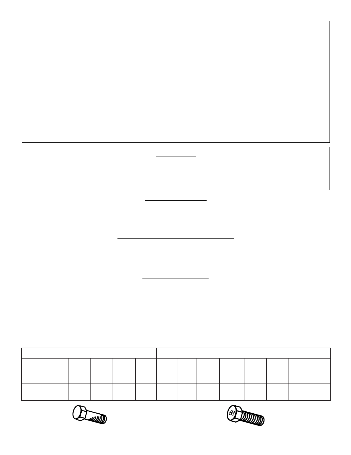
GRADE 8.8 (8G) - YELLOW COLOR GRADE 2 - SILVER COLOR
M6 M8 M10 M12 M16 M20 #10 ¹⁄₄ IN. ⁵⁄₁₆ IN. ³⁄₈ IN. ¹⁄₂ IN. ⁵⁄₈ IN. ³⁄₄ IN. 1 IN.
7 18 32 58 144 260 32 6 11 20 43 92 124 259
FT-LBS FT-LBS FT-LBS FT-LBS FT-LBS FT-LBS FT-LBS FT-LBS FT-LBS FT-LBS FT-LBS FT-LBS FT-LBS FT-LBS
9.5 24 43 79 195 353 3.6 8 15 27 58 125 168 351
N-m N-m N-m N-m N-m N-m N-m N-m N-m N-m N-m N-m N-m N-m
APPLY 24 N-m (18 FT-LBS) OF TORQUE TO M8 BOLT
APPLY 11 FT-LBS (15 N-m) OF TORQUE TO ⁵⁄₁₆ BOLT
BOLT TORQUE
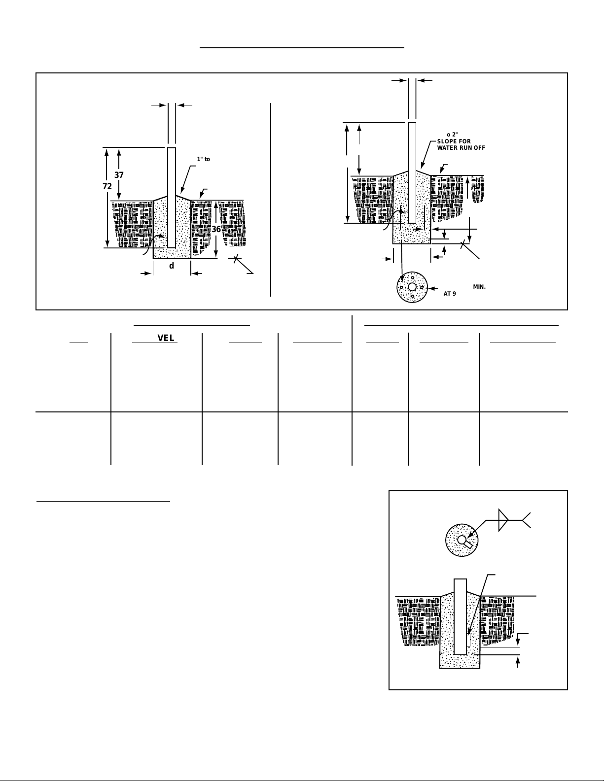
GROUND POLE INSTALLATION
2³⁄₈”O.D. x 72” LONG
72
37
d
36
1" to 2"
SLOPE FOR
WATER RUN OFF
GRADE
BELOW
FROST LINE
OVAL END
MIN.
DIA.
2³⁄₈" O.D.
PIER
FOUNDATIONS
72
37
d
48"
1" to 2"
SLOPE FOR
WATER RUN OFF
GRADE
BELOW
FROST LINE
OVAL END
MIN.
DIA.
NOTE:
48" may be
increased, concrete
and length of rebar
will increase
accordingly.
2³⁄₈" O.D.
DEEP
FROST LINE
FOUNDATIONS
(SEE NOTE)
1-1.5"
APPROX.
2"
(4) #3 x 24" MIN.
AT 90˚ APART
(SEE NOTE)
ANT WIND VEL. DIM “d” CONC VOL. DIM “d” CONC VOL. GROUND POLE
80 MPH 9” 1.5 FT
3
7” 1.2 FT
3
90 MPH 11” 2.2 FT
3
7” 1.2 FT
3
Mo.611652931
.90M 100 MPH 13” 3.0 FT
3
8” 1.5 FT
3
110 MPH 15” 4.0 FT
3
10” 2.4 FT
3
SEE NOTE 1
125 MPH 18” 5.8 FT
3
12” 3.5 FT
3
80 MPH 10” 1.8 FT
3
7” 1.2 FT
3
Mo.611652931
1.0M 90 MPH 13” 3.0 FT
3
8” 1.5 FT
3
100 MPH 15” 4.0 FT
3
9” 1.9 FT
3
SEE NOTE 2
108 MPH 16” 4.6 FT
3
10” 2.4 FT
3
PIER FOUNDATIONS DEEP FROST LINE FOUNDATIONS
POLE SPECIFICATIONS:
2” SCH 40 2³⁄₈” O.D.x .154 Wall x 72” Long Steel - CM PN 611652931 w/Oval End and
Powder Paint Finish.
1. When wind velocity exceeds 108 MPH on the .90m antenna at heights shown, the
ground pole must be a heavy wall pipe as f ollows:2” pipe (2³⁄₈” O.D .) Schedule 80
(.218”
wall thickness) and purchased locally.Field weld ¹⁄₄ x 1¹⁄₂ x 5 key as shown in
Fig.1.0
to prevent rotation in the concrete or use 3”O.D. ground pole and AZ/EL cap.
2. These charted values based on using Model 611652931 ground pole, 2.375 O.D. x
1.54 wall.When wind velocity exceeds 108 MPH, use 3”O.D .ground pole and AZ/EL
cap.
3. Pole and f oundation design based on the follo wing criteria:(a) Uniform Building Code
Exposure C and 1.5 stability factor , (b) Vertical soil pressure of 2000 pounds per square
foot, (c) Lateral soil pressure of 400 pounds per square foot, (d) Concrete compressive strength of 2500 pounds per square inc h in 28 days.
4. CAUTION - The foundation design shown does not represent an appropriate design
for any specific locality since soil conditions v ary and may not meet design criteria given
in Note 1.You should consult a local professional engineer to determine your soil conditions and appropriate foundation.
6"
APPROX.
KEY
¹⁄₄ x 1¹⁄₂ x 5
FIELD WELD
.21
.21
FIG. 1.0
L
A
d
36
(B)
1" to 2"
SLOPE FOR
WATER RUN OFF
GRADE
#3 REBAR X DIA. OF PIER,
INSERT THRU HOLE IN
TUBE & CENTER
BELOW
FROST LINE
MIN.
DIA.
NOTE:
Clearance
increases at
elevations
greater than 23˚.
3" O.D.
PIER
FOUNDATIONS
L
A
d
48"
(B)
1" to 2"
SLOPE FOR
WATER RUN OFF
GRADE
#3 REBAR
LENGTH = d MIN LESS 1"
INSERT THROUGH
HOLE IN TUBE & CENTER
(4) #3 x 24" MIN.
AT 90˚ APART
(SEE NOTE)
BELOW
FROST LINE
MIN.
DIA.
NOTE:
48" may be
increased, concrete
and length of rebar
will increase
accordingly.
3" O.D.
DEEP
FROST LINE
FOUNDATIONS
(SEE NOTE 2)
1-1.5"
APPROX.
2"
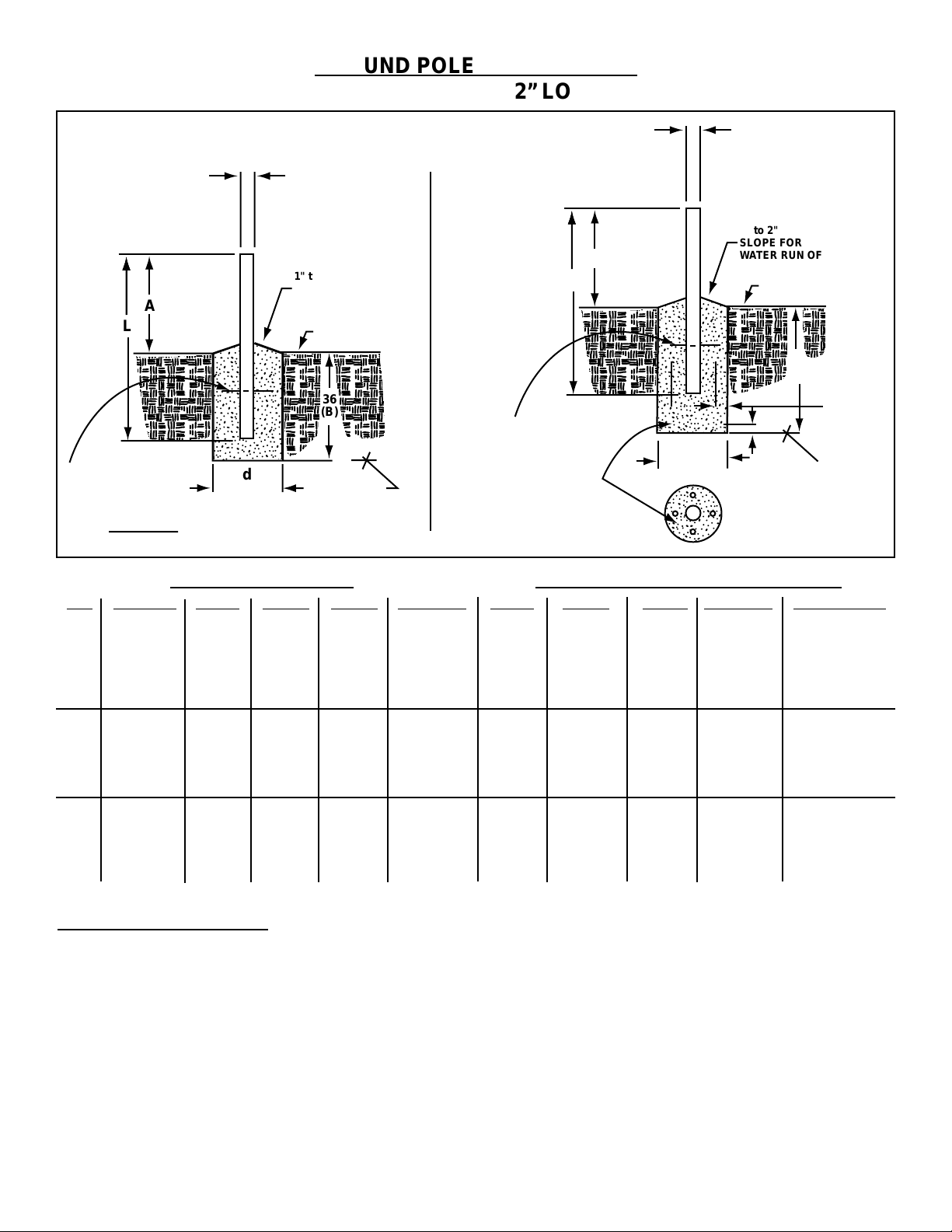
OPTIONAL
GROUND POLE INSTALLATION
3”O.D. x 68” & 72” LONG
ANT WIND VEL. DIM “L” DIM “A” DIM “d” CONC VOL. DIM “L” DIM “A” DIM “d” CONC VOL. GROUND POLE
80 MPH 9” 1.5 FT
3
7” 1.2 FT
3
90 MPH 11” 2.2 FT
3
7” 1.2 FT
3
.90M 110 MPH 68” 37” 13” 3.0 FT
3
68” 37” 8” 1.5 FT
3
Mo.611652731
110 MPH 15” 4.0 FT
3
10” 2.4 FT
3
See Note 2
125 MPH 18” 5.8 FT
3
12” 3.5 FT
3
80 MPH 10” 1.8 FT
3
7” 1.2 FT
3
90 MPH 13” 3.0 FT
3
8” 1.5 FT
3
1.0M 110 MPH 68” 37” 15” 4.0 FT
3
68” 37” 10” 2.4 FT
3
Mo.611652731
110 MPH 17” 5.2 FT
3
11” 2.9 FT
3
See Note 2
125 MPH 20” 7.2 FT
3
14” 4.7 FT
3
80 MPH 14” 3.5 FT
3
9” 1.9 FT
3
90 MPH 17” 5.2 FT
3
11” 2.9 FT
3
1.2M 110 MPH 72” 39” 19” 6.5 FT
3
72” 39” 13” 4.1 FT
3
Mo.611685101
110 MPH 22” 8.7 FT
3
15” 5.4 FT
3
See Note 2
125 MPH 25” 11.2 FT
3
19” 8.7 FT
3
PIER FOUNDATIONS DEEP FROST LINE FOUNDATIONS
POLE SPECIFICATIONS:
3” O.D.x .120 Wall x 68” Long Steel w/Powder Paint Finish - CM PN 611652731.
3” O.D.x .148 Wall x 72” Long Steel w/Powder Paint Finish - CM PN 611685101.
1. Pole and foundation design based on the following criteria: (a) Uniform Building Code Exposure C and 1.5 stability factor, (b) Vertical
soil pressure of 2000 pounds per square foot, (c) Lateral soil pressure of 400 pounds per square f oot, (d) Concrete compressiv e strength
of 2500 pounds per square inch in 28 days.
2. If Model 6851 (3” x 72”) is used for .90m and 1.0m Antenna Dimension “B” on pier foundation must be increased by 4” and concrete
volume will increase accordingly.
3. CAUTION - The foundation design shown does not represent an appropriate design for any specific locality since soil conditions vary
and may not meet design criteria given in Note 1.You should consult a local professional engineer to determine your soil conditions
and appropriate foundation.
 Loading...