


Instruction and Assembly Manual
2
0
°
3
50°
4
0
°
80
°
6
0°
7
0
°
1
0
°
Type 123
1.2m Rx/Tx ANTENNA SYSTEM
WITH
FACTORY ASSEMBLED AZ/EL CAP
©2000 Channel Master LLC
Printed in U.S.A.
8000636
6/99
Rev. A
World Headquarters (USA) • 1315 Industrial Park Drive, Smithfield, NC 27577 USA • Telephone: (919) 989-2205 • Fax: (919) 989-2200
International (GmbH) • Julius-Moser-Str. 13, 75179 Pforzheim, Germany • Telephone: +49 (0) 7231-14557-0 • Fax: +49 (0) 7231-14557-10
Europe (UK) • Croft Head Road, Blackburn, England BB1 5UE • Telephone:+44 (0) 1254 680444 • Fax:+44 (0) 1254 672299

VSAT ANTENNA/MOUNT/LNB
LIMITED TWELVE (12) MONTH WARRANTY
This CHANNEL MASTER®equipment is warranted to be free from defects in material and workmanship
under normal use and service. CHANNEL MASTER shall repair or replace defective equipment, at no charge,
or at its option, refund the purchase price, if the equipment is returned to CHANNEL MASTER not more than
twelve (12) months after shipment.Removal or reinstallation of equipment and its transportation shall not be
at the cost of CHANNEL MASTER except CHANNEL MASTER shall return repaired or replaced equipment
freight prepaid.
This Warranty shall not apply to equipment which has been repaired or altered in any way so as to affect its
stability or durability, or which has been subject to misuse, negligence or accident.This Warranty does not cover
equipment which has been impaired by severe weather conditions such as excessive wind, ice, storms,
lightning, or other natural occurrences over which CHANNEL MASTER has no control, and this Warranty shall
not apply to equipment which has been operated or installed other than in accordance with the instructions
furnished by CHANNEL MASTER.
Claimants under this Warranty shall present their claims along with the defective equipment to CHANNEL
MASTER immediately upon failure. Non-compliance with any part of this claim procedure may
invalidate this warranty in whole or in part.
THIS W ARRANTY IS EXPRESSLY IN LIEU OF ALL OTHER A GREEMENTS AND W ARRANTIES , ANY IMPLIED
WARRANTY OF MERCHANTABILITY OR FITNESS FOR A P AR TICULAR PURPOSE IS LIMITED IN DURATION
TO THE DURATION OF THIS WARRANTY. CHANNEL MASTER DOES NOT AUTHORIZE ANY PERSON TO
ASSUME FOR IT THE OBLIGATIONS CONTAINED IN THIS WARRANTY AND CHANNEL MASTER NEITHER
ASSUMES NOR AUTHORIZES ANY REPRESENTATIVE OR OTHER PERSON TO ASSUME FOR IT ANY
OTHER LIABILITY IN CONNECTION WITH THE EQUIPMENT DELIVERED OR PROVIDED.
IN NO EVENT SHALL CHANNEL MASTER BE LIABLE FOR ANY LOSS OF PROFITS, LOSS OF USE,
INTERRUPTION OF BUSINESS, OR INDIRECT, SPECIAL OR CONSEQUENTIAL DAMAGES OF ANY KIND.
In no event shall CHANNEL MASTER be liable for damages in an amount greater than the purchase price of
the equipment.
Some states do not allow limitations on how long an implied warranty lasts, or allow the exclusion or
limitation of incidental or consequential damages, so the above limitations or exclusions may not apply to you.
1

2
DATE DESCRIPTION REV.
11/97 ECN 9000000 Rel.
5/99 ECN 9004530 A

3
IMPORTANT!!!
INSTALLATION OF THIS PRODUCT SHOULD BE PERFORMED ONLY BY A PROFESSIONAL INST ALLER
AND IS NOT RECOMMENDED FOR CONSUMER D.I.Y. (DO-IT-YOURSELF) INSTALLATIONS.
DANGER!!!
WATCH FOR WIRES! Installation of this product near power lines is dangerous. For your own
safety, follow these important safety rules.
1. Perform as many functions as possible on the ground.
2. Watch out for overhead power lines. Check the distance to the power lines before starting installation.We recommend you stay a minimum of 6 meters (20 feet) from all power lines.
3. Do not use metal ladders.
4. Do not install antenna or mast assembly on a windy day.
5. If you start to drop antenna or mast assembly, get away from it and let it fall.
6. If any part of the antenna or mast assembly comes in contact with a power line, call your local
power company. DO NOT TRY TO REMOVE IT YOURSELF! They will remove it safely.
7. Make sure that the mast assembly is properly grounded.
WARNING!!!
Assembling dish antennas on windy days can be dangerous.Because of the antenna surface, even
slight winds create strong forces. For example, a 1.0m antenna facing a wind of 32 km/h (20 mph)
can undergo forces of 269 N (60 lbs). Be prepared to safely handle these forces at unexpected
moments. Do not attempt to assemble, move or mount a dish on windy days or serious, even fatal
accidents may occur. Channel Master
®
is not responsible or liable for damage or injury resulting
from antenna installations.
WARNING!!!
Antennas improperly installed or installed to an inadequate structure are very susceptible to wind
damage.This damage can be very serious or even life threatening. The owner and installer assumes
full responsibility that the installation is structurally sound to support all loads (weight,wind & ice) and
properly sealed against leaks. Channel Master will not accept liability for any damage caused by a
satellite system due to the many unknown variable applications.

4
ASSEMBLY TOOLS REQUIRED
1 - Compass 1 - 10mm Nut Driver 1 - 13mm Deep Socket (³⁄₈”Drive)
1 - Clinometer 1 - 10mm Socket (³⁄₈” Drive) 1 - 9” Magnetic Level
1 - 10” Adjustable Wrench 1 - Phillips Screwdriver (#1 or #2) 1 - 13mm Combination Wrench
1 - Ratchet Wrench (³⁄₈” Drive) 1- Torque Wrench 1 - 10mm Combination Wrench
PREINSTALLATION MA
TERIALS CHECKLIST
Grounding Rod Clamp & Grounding Block - As Required by National Electric Code or local codes.
Ground Wire - #10 solid copper as or required by National Electric Code or local codes (length required).
Concrete - (See Ground Pole section for quantity and grade).
#3 Rebar - (See Ground Pole section for quantity). Deformed steel per ASTM A615, grade 40 or 60.
SITE SELECTION
The first and most important consideration when
choosing a prospective antenna site is whether or not the
area can provide an acceptable “look angle” at the
satellites. A site with a clear, unobstructed view is preferred. Also consider obstruction that may occur in the
future such as the growth of trees.Y our antenna site must
be selected in advance so that you will be able to receive
the strongest signal available. To avoid microwave
interference, obstructions, etc.conduct an on-site sur vey
with a portable antenna.
As with any other type of construction, a local building
permit may be required before installing an antenna.It is
the property owner’s responsibility to obtain any and all
permits.
Before any digging is done, information regarding the
possibility of underground telephone lines, power lines,
storm drains, etc. in the excavation area should be
obtained from the appropriate agency.
Because soils vary widely in composition and load
capacity, consult a local professional engineer to
determine the appropriate foundation design and
installation procedure. A suggested foundation design
with conditions noted is included in this manual for
reference purposes only.
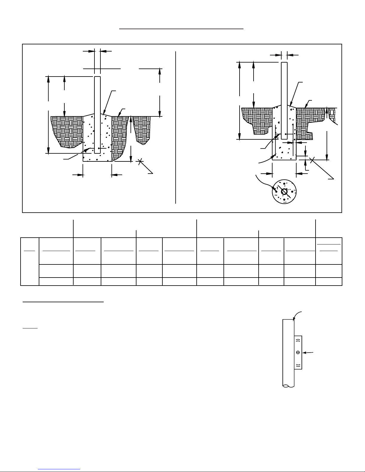
GROUND POLE INSTALLATION
MIN.
DIA.
d
d
MIN.
DIA.
ANT
3.00" O.D.
3.00" O.D.
40"
C
L
72"
39.9"
39.9"
increased,
72"
40.9"
50" depth may be
will increase
length of rebar
concrete and
accordingly.
2"
2"
50"
NOTE:
#3 REBAR x DIA. OF PIER, INSERT
FROST LINE
#3 REBAR x
DIA. OF PIER
INSERT THRU HOLE
IN TUBE & CENTER
AT 90° APART
(SEE NOTE)
(4)#3x24"MIN.
BELOW
THRU HOLE IN TUBE & CENTER
1" to 2"
WATER RUN OFF
GRADE
SLOPE FOR
BELOW
FROST LINE
APPROX.
1" to 2"
SLOPE FOR
(SEE
NOTE)
GRADE
WATER RUN OFF
GROUND
ANT WIND VEL. DIM “d” CONC VOL. DIM “d” CONC VOL. DIM “d’ CONC VOL. DIM “d” CONC VOL. POLE
80 MPH 8” 1.3 13” 3.4 8” 1.6 10” 2.5 “A”
90 MPH 10” 2.0 16” 5.1 8” 1.6 12” 3.6
1.2M 100 MPH 12” 2.9 18” 6.5 8” 1.6 13” 4.2 “A” or
LFL 110 MPH 14” 3.9 21” 8.8 10” 2.5 16” 6.4 “B”
125 MPH 17” 5.8 24” 11.5 12” 3.6 19” 9.0 “B” Only
POLE SPECIFICATIONS:
Ground Pole “A” = 3.00 O.D. x 9 G.A. (.148 Wall) x 72” Steel
Ground Pole “B” = 3.00 O.D. x .250 Wall x 72”Steel ASTM 120 Mech Tubing
NO
TE:
Pole “A” is supplied from factory powder painted and with hole for #3 rebar and grounding screw.
Pole “B” not supplied and must be field drilled ⁵⁄₈” dia. for #3 rebar and drilled .218 for ¹⁄₄-20 self tapping
grounding screw and galvanized or painted for protection.
1 - Pole and foundation design based on the following criteria:
a) Uniform building code exposure B or C and 1.5 stability factor.
b) Vertical soil pressure of 2000 pounds per square foot.
c) Lateral soil pressure of 400 pounds per square foot.
d) Concrete compressive strength of 2500 pounds per square inch in 28 days.
2 - CAUTION- The foundation design sho wn does not represent an appropriate design for an y specific locality since soil conditions v ary
and may not meet design criteria given in Note 1.You should consult a local professional engineer to determine your soil conditions
and appropriate foundation.
Exposure “B” Exposure “C” Exposure “B” Exposure “C”
PIER FOUNDATIONS DEEP FROST LINE FOUNDATIONS
5
Ground Pole
Must Be
Vertical In
All Directions
Within .19 Inches
At T op (0.3˚)
Bubble
Level

ASSEMBLY AND INSTALLATION
INSTALLING AZ/EL CAP MOUNT ONTO POLE
The AZ/EL Cap is factory preassembled, therefore, no
assembly is required.
Before installing AZ/EL Cap, concrete foundation should
be in place and cured.
Install AZ/EL Cap onto ground pole.If ground pole is 2⁷⁄₈”
O.D., install Item 3 vinyl cap as shown. Square Head
Locking Bolts should be tightened enough to penetrate
vinyl cap only. Item 3 is not used with 3” O.D. ground
pole.Tighten clamp nuts so that cap is held stationary on
the ground pole, but can be s wiv eled with slight pressure
(Ref. Fig. 1.0).
ASSEMBLING ANTENNA ONT
O AZ/EL CAP MOUNT
Install four M8 x 91mm Plow Bolts into holes in reflector
face.Lift reflector and inser t exposed por tion of bolt into
holes in Antenna Mount flange.Install four Lock W ashers
and Hex Nuts on Bolts.Ref. 1.1.
Tighten and torque to 11 Ft. Lbs (15 N-m).
IMPORTANT: Note orientation of bolt holes in reflector
flange.Holes should be located on each side and bottom
of reflector as shown in Figure 1.1.
FEED AND FEED LEG INST
ALLATION
Assemble Feed Legs to antenna (Ref. 1.2).
Insert M8 x 20mm Hex Bolt and Flat Washer thru hole in
bottom flange of reflector. Assemble Bottom Feed Leg
and secure with Lock Washer and Hex Nut.
NOTE: Bottom Feed Support Leg is the shorter one and
has two holes on one end.
Attach left and right Feed Legs to reflector using M6 x
16mm Hex Bolts, Flat Washers, Lock Washer and Hex
Nuts. (Note: Long formed end attaches to reflector.)
Assemble Feed Support Block (supplied with Feed
Package) to Feed Support Legs, using M6 x 16mm Hex
Bolts, Lock Washers, and Hex Nuts.
NOTE:Support Block is supplied with Feed P ac kage.On
some models, it may be easier to assemble Feed Block
to Feed Legs, by removing Feed Horn Assembly from
Feed Support Block.
Refer to feed assembly instructions (included with feed
package) for assembly of ODU to feed.
Tighten and torque hardware securing Side and Bottom
Feed Legs to Feed Support Block and to Reflector to 4
Ft-lbs. (5.4 N-m).
FIG. 1.0 - Installing AZ/EL Cap Mount onto
Ground Pole/Assembling Antenna
and Antenna to AZ/EL Cap Mount
Assembly
FIG. 1.1 - Installation of Feed/Feed Support
Legs to Antenna
6
10°
20°
4
0
°
0°
5
°
0
6
°
0
7
°
0
8
MOUNT ASSEMBLY
LOCK WASHER
(4 REQ)
HEX
NUT
(4 REQ)
CLAMP
BOLTS
LOCKING
BOLTS
GROUND
TUBE
PLOW BOLT
(4 REQ)
SIDE BOLT
HOLE
3
BOTTOM
BOLT
HOLE
SIDE FEED LEG
HEX BOLT
FLAT W ASHER
(2 REQ-BOTH SIDES)
4
HEX BOLT
LOCK WASHER
(2 REQ)
(2 REQ-BOTH SIDES)
(2 REQ)
FEED HORN/FEED ASSY
W/MOUNTING BLOCK
HEX BOLT
LOCK WASHER
HEX NUT
HEX BOLT
FLAT W ASHER
HEX NUT
MOUNTING BLOCK
BOTTOM FEED
LEG

7
FIG. 2.1 - GROUNDING FEED CABLES
FIG. 2.0 - Typical Electrical Grounding for Antenna Ground Pole
NOTE: All installations to conform to latest issue of
National Electrical Code.
Ground antenna mount assembly and feed cables in
accordance with current National Electrical Code and
local electrical codes. Figure 2.0 and 2.1 illustrates
typical grounding methods for the ground pole and
feed cables.
Clamps that provide a solid connection between ground
wire and ground source should be used.
Tighten and torque all hardware.
IMPORTANT: Sealing RF Coaxial Connector: The
copper-plated center conductor in the RF coaxial cable,
which connects receiver to LNB, can experience
electrolysis corrosion at the LNB connector. Moisture
and DC current causes this type of corrosion.To prevent
corrosion, apply a moderate coat of silicon grease to the
center conductor and wrap the entire connection with
COAX-SEAL
®
tape to seal.
GROUNDING
25"/29"
APPROX.
7"/3" REF.
GROUND POLE
Apply sealant here, after assembly,
to improve corrosion resistance.
DRILL HOLE THRU ONE WALL WITH
7/32" DIA. TWIST DRILL
1/4" EXTERNAL TOOTH
LOCK WASHER
GROUND LUG
TYPE "D" POINT, SELF TAPPING SCREW
GROUND WIRE
NOTE:
IMPORTANT:
DRILL HOLE AND ATTACH
GROUND BEFORE POURING
CONCRETE INSIDE GROUND POLE.
1/4"-20 UNC X 5/8" HEX HEAD,
Refer to NEC Section 810 and local electric
codes for the specific area requirements.
ALL INSTALLATIONS TO CONFORM
TO THE LATEST ISSUE OF THE
NATIONAL ELECTRIC CODE.
(Typical #10 AWG Copper, #8 Aluminum)
NEC SECTION 810-20
*Coaxial Cable
To Receiver
*Ground Block
NEC SECTION 810-20
*Groundwire
*Coaxial Cable
From LNB
*Items Not
Supplied

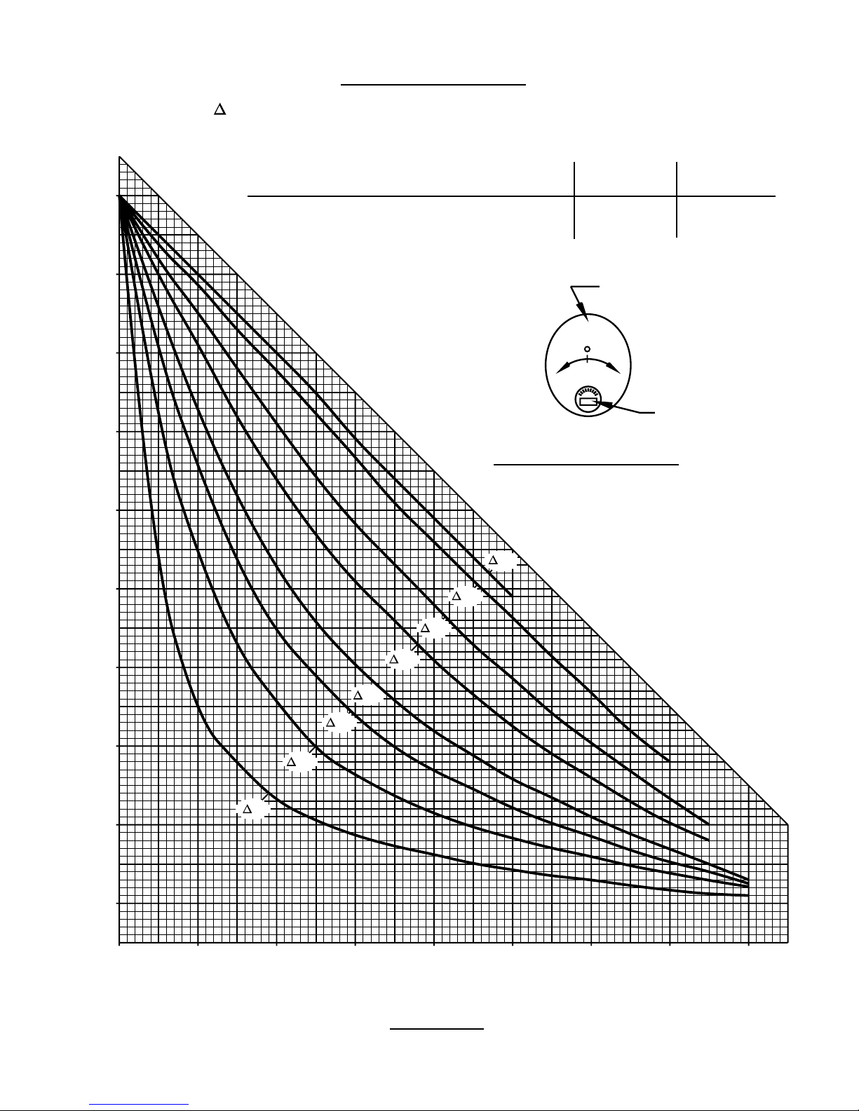
ANTENNA ALIGNMENT PROCEDURE
Alignment with the satellite is obtained by setting polarization, elevation and azimuth. Charts 1, 2 & 3 are to
determine these values for your earth station antenna
site. “∆L” is the difference between the earth station
antenna site longitude and the satellite longitude. Use
“∆L”and your ear th station latitude to obtain polar ization,
elevation or azimuth setting.
POLARIZA
TION OF THE FEED
Loosen feed horn clamp bolts and turn feed clockwise or
counterclockwise, depending on being east or west of
the satellite as shown on Chart 1. Align marks on the
horn clamp and appropriate mark on the horn scale
Polarization chart assumes antenna system polarization
is Tx vertical and satellite ver tical Pol is perpendicular to
plane of geostationary arc. For horizontal Tx of antenna,
feed must be rotated 90˚ from values shown. (Starting
point for polarization adjustment is 0˚, as shown in Figure
3.0.)
Use a signal strength measuring device for final polar-
ization setting and tighten horn clamp bolts to 4 Ft-lbs.
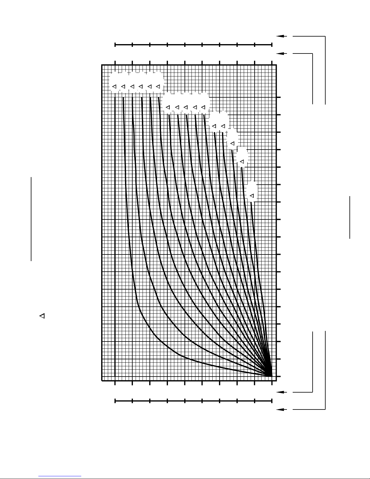
ELEV
ATION
Use Chart 2 and determine your elevation setting.
Loosen bolts in curved slots (both sides) of AZ/EL hous-
ing approximately ¹⁄₂ turn (Ref. Fig. 3.1). Turn elevation
adjustment bolt clockwise to increase elev ation.Align the
edge of the clamp with appropriate mark on housing at
the desired elevation reading.This will be an approximate
setting. Optimum setting achieved when fine tuning.
AZIMUTH
Use Chart 3 and determine your azimuth setting. Values
in chart must be adjusted for magnetic deviation for your
location for correct compass reading. Rotate reflector
and mount pointing it to the correct compass reading.
Slowly sweep the antenna in azimuth until signal is
found. If the desired signal is not found, increase or
decrease elevation setting and repeat the azimuth sweep
(Ref. Fig. 3.2). Tighten clamp bolts and clamp locking
bolts.
FINE
TUNING
Use signal tuning device for final adjustments to obtain
maximum antenna performance. Alternate between elevation and azimuth fine tuning to reach maximum signal
strength, until no improvement can be detected. Certain
models utilize the optional azimuth fine tune feature
(refer to Figure 3.2). This allows the azimuth to be fine
tuned by loosening the (4) carriage bolts and swivel nut
hex nut which allows adjusting the azimuth fine tune
adjusting bolt for the peak signal.Tighten and torque all
AZ/EL hardware to 12 Ft-lbs.
FIG. 3.0 - Polarization of the Feed
FIG. 3.1 - Setting the Elevation
FIG. 3.2 - Rotating Antenna for Azimuth
Example
Shown
Set @ 18˚
8
HORN SCALE
+400-40
3040946
CLAMP BOLT
ALIGNMENT MARK
EDGE OF CLAMP
BRACKET
20°
40°
10°
20°
4
0
°
0°
5
°
0
6
°
70
°
0
8
ELEVATION ADJUSTING SCREW
CURVED SLOT BOLT
ELEVATION PIVOT
CLAMP BOLT
CLAMP LOCKING BOLT
BOLT
AZIMUTH FINE TUNE
ADJUSTING BOLT
HEX NUT,
CARRIAGE BOLT
(4)
HEX NUT,
SWIVEL NUT
90
9
80
70
60
POLARIZATION CHART
" L" IS THE DIFFERENCE BETWEEN THE EARTH STATION
ANTENNA SITE LONGITUDE AND THE SATELLITE LONGITUDE
NORTHERN SOUTHERN
POLARIZATION CHART SIGN VALUES (+ OR -) HEMISPHERE HEMISPHERE
ANTENNA SITE WEST OF SATELLITE LONGITUDE - +
ANTENNA SITE EAST OF SATELLITE LONGITUDE + -
ANTENNA
+–
FEED
Feed Rotation (Facing Antenna)
50
40
30
POLARIZATION + OR – (SEE ILLUSTRATION)
20
10
For + Polarization, Rotate CCW (Counter Clockwise)
For - Polarization, Rotate CW (Clockwise)
75°
60°
40°
30°
20°
15°
10°
5°
0
0 1020304050607080
EARTH STATION LATITUDE IN DEGREES NORTH OR SOUTH OF EQUATOR
CHART 1

10
ELEVATION CHART
" L" IS THE DIFFERENCE BETWEEN THE EARTH STATION
ANTENNA SITE LONGITUDE AND THE SATELLITE LONGITUDE
90
80
70
60
50
5°
10°
15°
20°
25°
30°
35°
37.5
42.5
40°
°
47.5
45°
35°
32.5
°
50°
°
°
27.5
25°
30°
125
°
°
120°
115°
110°
105°
100°
95°
90°
85
65°
70°
75°
80°
°
30
°
27.5
25
35°
°
32.5°
°
50°
40°
37.5
47.5
45°
°
42.5
°
°
40°
40
30
45°
50°
ELEVATION IN DEGREES
55°
60°
20
65°
10
70°
75°
0
0 1020304050607080
EARTH STATION LATITUDE IN DEGREES NORTH OR SOUTH OF EQUATOR
360
11
0
HEMISPHERE
SOUTHERN
0°
350
340
330
320
310
300
290
280
270
10
20
30
40
50
60
70
80
90
5°
10°
15°
20°
25°
35°
40°
45°
30°
50°
55°
60°
WEST EASTWESTEAST
65°
70°
75°
CHART 3
AZIMUTH CHART
" L" IS THE DIFFERENCE BETWEEN THE EARTH STATION
ANTENNA SITE LONGITUDE AND THE SATELLITE LONGITUDE
180
170
160
150
140
130
120
110
90
EARTH STATION ANTENNA LATITUDE (IN DEGREES NORTH OR SOUTH OF EQUATOR)
0 5 10 15 20 25 30 35 40 45 50 55 60 65 70 75 80
270
[AZIMUTH COLUMN READING WHEN EARTH STATION IS EAST OF SATELLITE]
[AZIMUTH COLUMN READING WHEN EARTH STATION IS WEST OF SATELLITE]
180
HEMISPHERE
NORTHERN
190
200
210
220
230
240
250
260
270
EARTH STATION ANTENNA AZIMUTH (IN DEGREES)

12
APPENDIX - A
1.2m ANTENNA SURVIVAL WINDLOADS AT 125 MPH VELOCITY
BEAM AXIS
°
0
1
0°
2
3
0°
4
5
0
°
6
0°
7
0
°
8
0
F
H
°
OFFSET
MECHANICAL AXIS
(NORMAL TO ANTENNA FACE)
40.9
M
T
16.97°
F
V O
M
F=
H
F
V
M
T
M
O
HORIZONTAL FORCE
VERTICAL FORCE
=
TORSIONAL MOMENT
=
OVERTURNING MOMENT
=
BASED ON 40.9" FROM MOUNTING SURFACE TO CENTER LINE OF ANTENNA.
M
O
ELEVATION DEGREES
MECHANICAL
0
10
20
30
40
50
60
70
BEAM
17
27
37
47
57
67
77
87
FORCE (POUNDS)
F
H
1285
1217
1182
1071
943
822
686
515
F
-35
-257
-497
-711
-857
-943
-985
-762
MOMENTS
V
M
T
500
488
464
421
357
299
232
178
(FT-LBS/N-m)
M
O
4,380
4,148
4,029
3,650
3,214
2,802
2,338
2,096
Values shown represent
maximum forces for
any wind direction
and include 1.5 F .
Height and
exposure factors from
uniform building code
S

13
PARTS LIST
ITEM DESCRIPTION QTY.
1 BOLT, PLOW, SPECIAL, M8 x 91mm 4
2 REFLECTOR, 1.2m LFL 1
3 CAP VINYL 1
4 WASHER, LOCK, SS, ⁵⁄₁₆ 5
6 MOUNT ASSEMBLY, 1.2m LFL, LT DTY 1
7 BOLT, HEX HD M8 x 20mm 1
8 NUT, HEX, SS, M8 1
10 BOLT, HEX HD M6 x 16mm 6
11 WASHER, LOCK, SS, ¹⁄₄ 6
12 FEED SUPPORT TUBE, BOTTOM 1
13 NUT, HEX M6 2
14 FEED SUPPORT TUBE, SIDE 2
FEED/SUPPORT
BLOCK ASSEMBLY
-4
0
10
1
2
10°
2
0
°
3
40°
°
0
5
°
0
6
°
0
7
°
0
8
8
4
14
11
6
13
7
11
12
10
11
10
3
4
8

HARDWARE SORTER
BOLT, PLOW, SPECIAL
M8 x 91MM
ITEM 1
HEX HD CAP SCREW, SS
M8 x 20MM
ITEM 7
Hardware illustrations are true size. Place actual hardware on top of illustration to identify.
HEX HD CAP SCREW, SS
M6 x 16MM
ITEM 10
 Loading...