

Changhong Electric PF2939 Service Manual

FILE NO. SM-CTV-G-005
COLOR TELEVISION
SERVICE MANUAL
MODEL NO. PF2939
CHASSIS NO. CH-16CD
Please read this manual carefully before service.

SERVICE MANUAL
TABLE OF CONTENTS
SAFETY INSTRUCTIONS AND MAINTENANCE
.....................................1
X-Ray Radiation Precaution...............................................................................................1
Safety Precaution ................................................................................................................1
Product Safety Notice .........................................................................................................2
Maintenance.......................................................................................................... 3
KEY ICS AND ASSEMBLIES..................................................................................4
SYSTEM BLOCK DIAGRAMS...............................................................................5
Structure Block Diagram.....................................................................................................5
Block Diagram for Supply Voltage System .....................................................................6
SERVICE DATA................................................................................................................7
Technical Data of Key ICs..................................................................................................7
Service Data of Key ICs .....................................................................................................21
Waveforms of Key Points...................................................................................................27
ADJUSTMENTS ..............................................................................................................34
Set-up Adjustments .............................................................................................................34
Circuit Adjustments..............................................................................................................36
Service Mode and Bus Data..............................................................................................38
APPENDIX
Circuit Diagrams

SERVICE MANUAL
SAFETY INSTRUCTIONS AND MAINTENANCE
WARNING: BEFORE SERVICING THIS CHASSIS, READ THE “X-RAY RADIATION
PRECAUTION”, “SAFETY PRECAUTION”AND “PRODUCT SAFETY NOTICE
”
INSTRUCTIONS BELOW.
X-RAY RADIATION PRECAUTION
1. The EHT must be checked every time the TV is serviced to ensure that the CRT does not emit
X-ray radiation as result of excessive EHT voltage. The maximum EHT voltage permissible in
any operating circumstances must not exceed the rated value. When checking the EHT, use
the High Voltage Check procedure in this manual using an accurate EHT voltmeter.
2. The only source of X-RAY radiation in this TV is the CRT. The TV minimizes X-RAY radiation,
which ensures safety during normal operation. To prevent X-ray radiation, the replacement
CRT must be identical to the original fitted as specified in the parts list.
3. Some components used in this TV have safety related characteristics preventing the CRT
from emitting X-ray radiation. For continued safety, replacement component should be made
after referring the PRODUCT SAFETY NOTICE below.
4. Service and adjustment of the TV may result in changes in the nominal EHT voltage of the
CRT anode. So ensure that the maximum EHT voltage does not exceed the rated value after
service and adjustment.
SAFETY PRECAUTION
WARNING: REFER SERVICING TO QUALIFIED SERVICE PERSONNEL ONLY.
1. The TV has a nominal working EHT voltage. Extreme caution should be exercised when
working on the TV with the back removed.
1.1 Do not attempt to service this TV if you are not conversant with the precautions and
procedures for working on high voltage equipment.
1.2 When handling or working on the CRT, always discharge the anode to the TV chassis before
removing the anode cap in case of electric shock.
1.3 The CRT, if broken, will violently expel glass fragments. Use shatterproof goggles and take
extreme care while handling.
1.4 Do not hold the CRT by the neck as this is a very dangerous practice.
2. It is essential that to maintain the safety of the customer all power cord forms be replaced
exactly as supplied from factory.
3. Voltage exists between the hot and cold ground when the TV is in operation. Install a suitable
isolating transformer of beyond rated overall power when servicing or connecting any test
equipment for the sake of safety.
1

SERVICE MANUAL
4. When replacing ICs, use specific tools or a static-proof electric iron with small power (below
35W).
5. Do not use a magnetized screwdriver when tightening or loosing the deflection yoke assembly
to avoid electronic gun magnetized and decrement in convergence of the CRT.
6. When remounting the TV chassis, ensure that all guard devices, such as nonmetal control
buttons, switch, insulating sleeve, shielding cover, isolating resistors and capacitors, are
installed on the original place.
7. Replace blown fuses within the TV with the fuse specified in the parts list.
8. When replacing wires or components to terminals or tags, wind the leads around the terminal
before soldering. When replacing safety components identified by the international hazard
symbols on the circuit diagram and parts list, it must be the company-approved type and must
be mounted as the original.
9. Keep wires away from high temperature components.
PRODUCT SAFETY NOTICE
CAUTION: FOR YOUR PROTECTION, THE FOLLOWING PRODUCT SAFETY NOTICE
SHOULD BE READ CAREFULLY BEFORE OPERATING AND SERVICING THIS TV SET.
1. Do not slap or beat the cabinet or CRT, since this may result in fire or explosion.
2. Never allow the TV sharing a plug or socket with other large-power equipment. Doing so may
result in too large load, thus causing fire.
3. Do not allow anything to rest on or roll over the power cord. Protect the power cord from being
walked on, modified, cut or pinched, particularly at plugs.
4. Do not place any objects, especially heavy objects and lightings, on top of the TV set. Do not
install the TV near any heat sources such as radiators, heat registers, stove, or other
apparatus that produce heat.
5. Service personnel should observe the SAFETY INSTRUCTIONS in this manual during use
and servicing of this TV set. Otherwise, the resulted damage is not protected by the
manufacturer.
6. Many electrical and mechanical components in this chassis have special safety-related
characteristics. These characteristics are often passed unnoticed by a visual inspection and
the X-ray radiation protection afforded by them cannot necessarily be obtained by using
replacements rated at higher voltages or wattage, etc. Components which have these special
safety characteristics in this manual and its supplements are identified by the international
hazard symbols on the circuit diagram and parts list. Before replacing any of these
components read the parts list in this manual carefully. Substitute replacement components
which do not have the same safety characteristics as specified in the parts list may create
X-ray radiation.
2
SERVICE MANUAL
Safety Symbol Description
The lightning symbol in the triangle tells you that the voltage inside this product may
be strong enough to cause an electric shock. Extreme caution should be exercised
when working on the TV with the back removed.
This is an international hazard symbol, telling you that the components identified by
the symbol have special safety-related characteristics.
FDA This symbol tells you that the critical components identified by the FDA marking have
special safety-related characteristics.
UL This symbol tells you that the critical components identified by the UL marking have
special safety-related characteristics.
MAINTENANCE
1. Install the TV set on a stable and level surface. Do not place the set near or over a radiator or
heat register, or where it is exposed to direct sunlight.
2. Do not install the TV set in a place exposed to rain, water, excessive dust, mechanical
vibrations or impacts.
3. Allow enough space (at least 10cm) between the TV and wall or enclosures for proper
ventilation.
4. Slots and openings in the cabinet should never be blocked by clothes or other objects.
5. Please power off the TV set and disconnect it from the wall immediately if any abnormal
condition are met, such as bad smell, belching smoke, sparkling, abnormal sound or no
picture/sound/raster. Hold the plug firmly when disconnecting the power cord.
6. Unplug the TV set from the wall outlet before cleaning or polishing it. Use a dry soft cloth for
cleaning the exterior of the TV set or CRT screen. Do not use liquid cleaners or aerosol
cleaners.
3
SERVICE MANUAL
KEY ICS AND ASSEMBLIES
Table 1 Key ICs and Assemblies
Serial
No.
Position
No.
Model No. Function Description
1 N201 OM8373PS(CH05T1632) UOC
2 N202 AT24C16 EEPROM
3 N301 TA1343N Audio processor
4 N401 TDA8350 Vertical output circuit
5 N361 TDA8944J Sound power amplifier
6 N901 TA1219AN TV/AV switch circuit
7 IC801 STR-G8656 Power supply circuit
8 A101 TDQ-6F2-M Tuner
4
SERVICE MANUAL
SYSTEM BLOCK DIAGRAMS
5
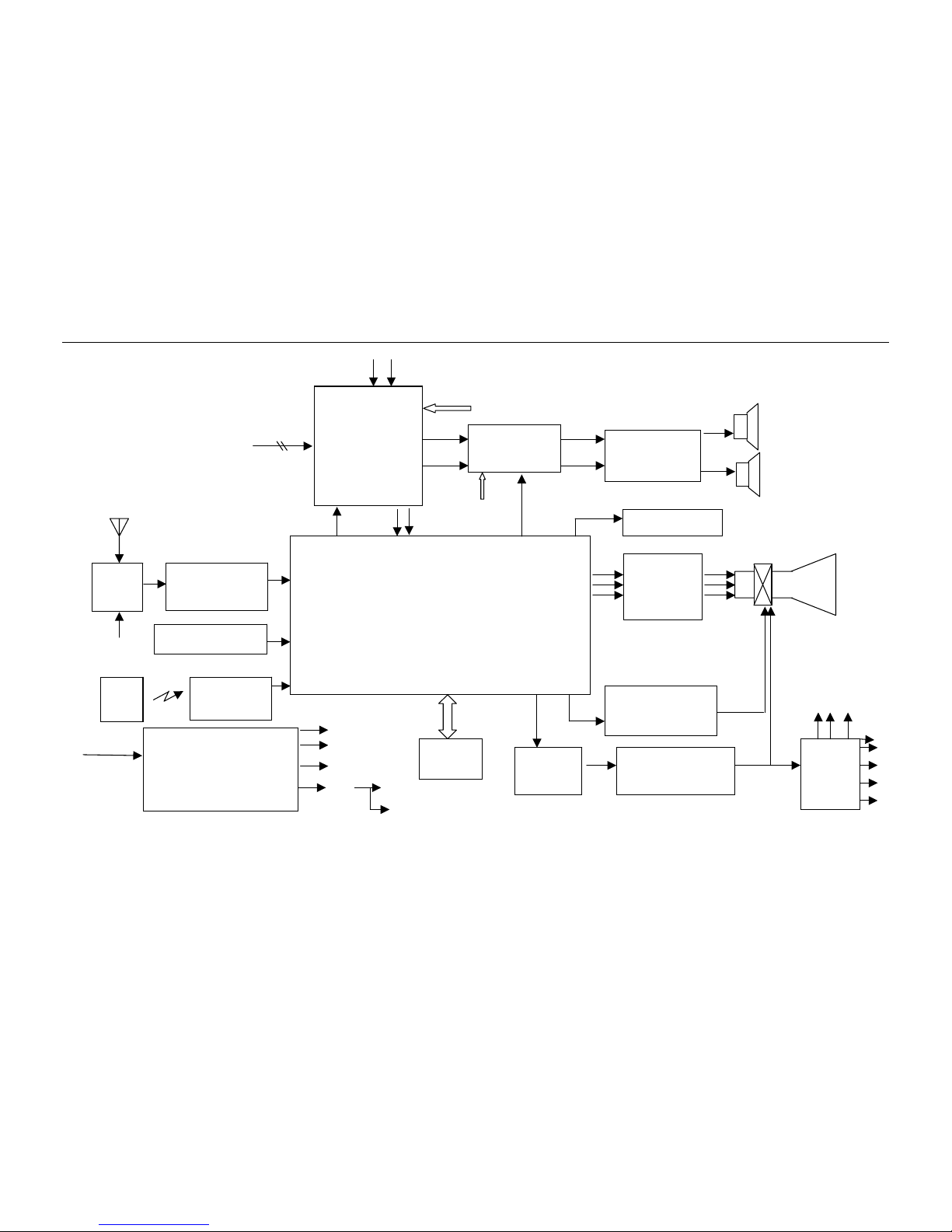
Structure Block Diagram
Fig 1. Structure Block Diagram for CH-16CD Chassis
Lin
Rin
UOC (27)
IF Pre-Amplifier
+ SAWF
Tuner
A101
EEPROM
(N202)
I2C
100~250V
50/60Hz
Power Supply Circuit
STR-G8656 (IC801) And
BCK-24217L (T803)
5V-1
15V-1
3.3V
15V-2
145V
8V
Circuit for Buttons
On The TV
Remote Sensor
HS0038
Remote
control
200V
Monitor Out
V.OUT
TDA8350Q (N401)
UOC
OM8373PS
(N201)
CRT Drive
H.Drive
Q501, T501
H.OUT
Q502
FBT
T502
Y/C TV-V
I2C
SIF
Audio Amplifier
TDA8944J (N361)
AV Switch
TA1218/1219
(N901)
Audio Processor
TA1343N (N301)
C
Y
I2C
AV Terminals in
35
42 43
40
23
24
53
52
51
6
7
33
21 22
64
HV FV SV
45V
16V
5V-2
9V
SERVICE MANUAL
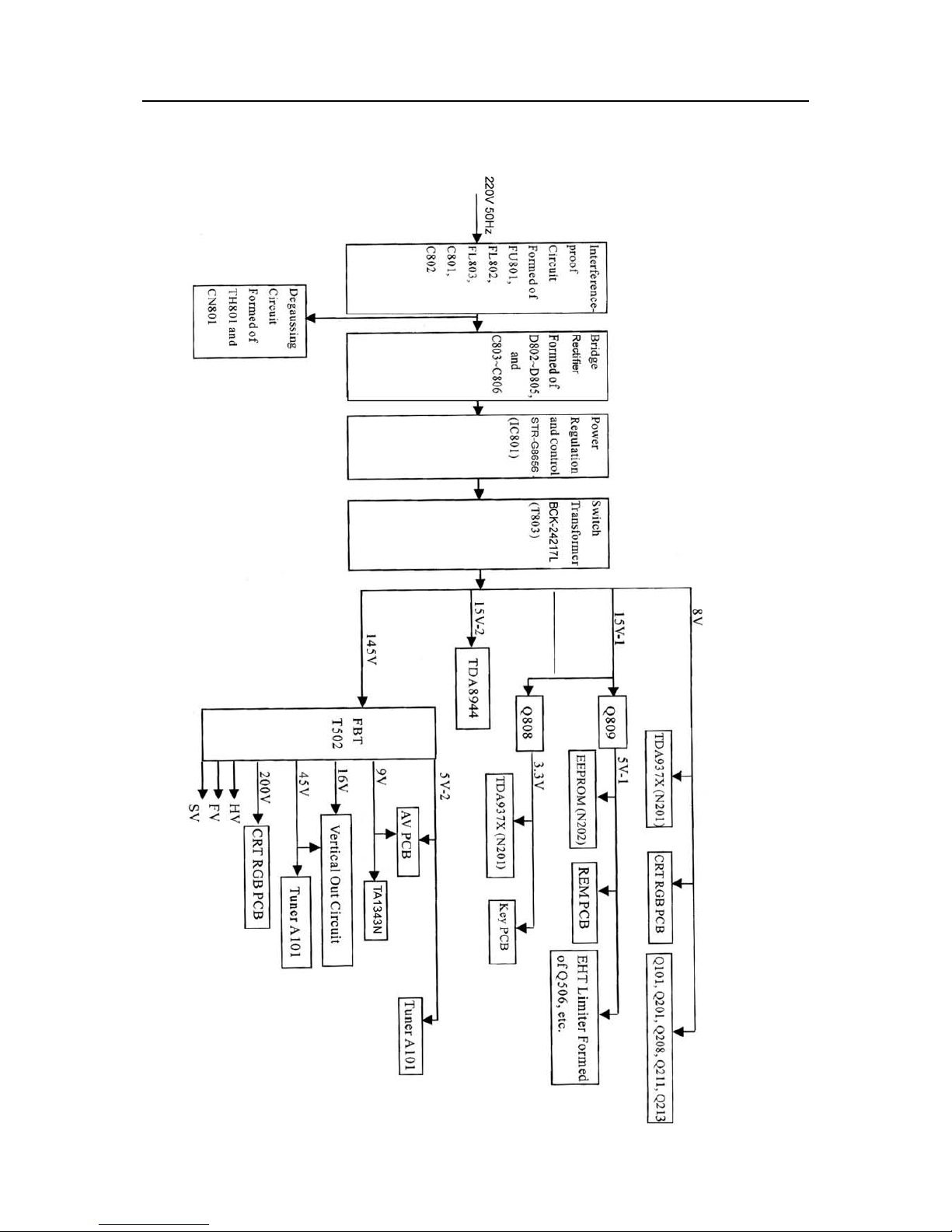
Block Diagram for Supply Voltage System
Fig 2 Block Diagram for Supply Voltage System for CH-16CD Chassis
6

SERVICE MANUAL
SERVICE DATA
Technical Data of Key ICs
OM8373PS (N201)
UOC
1. General Description
The various versions of the OM8373 PS/ N3/A
series combine the functions of a video
processor together with a μ-Controller and
US Closed Caption decoder. The ICs are
intended to be used in economy television
receivers with 90° and 110° picture tubes.
The ICs have supply voltages of 8V and 3.3V
and they are mounted in an S-DIP 64
envelope.
The features are given in the following feature
list.
2. Features
TV-signal processor
• Multi-standard vision IF circuit with
alignment-free PLL demodulator
• Internal (switchable) time-constant for the
IF-AGC circuit
• A choice can be made between versions with
mono intercarrier sound FM demodulator and
versions with QSS IF amplifier.
• The mono intercarrier sound versions have a
selective FM-PLL demodulator which can be
switched to the different FM sound
frequencies (4.5/5.5/6.0/6.5 MHz).
The quality of this system is such that the
external band-pass filters can be omitted.
• Source selection between ‘internal’ CVBS and
external CVBS or Y/C signals
• Integrated chrominance trap circuit
• Integrated luminance delay line with
adjustable delay time
• Picture improvement features with peaking
(with variable positive/negative overshoot
ratio), black stretching and Dynamic Skin
Tone Control
• Integrated chroma band-pass filter with
switchable centre frequency
• Only one reference (12 MHz) crystal
required for the μ-Controller, Teletext- and
the colour decoder
• PAL/NTSC colour decoder with automatic
search system
• Internal base-band delay line
• RGB control circuit with ‘Continuous Cathode
Calibration’, white point and black level offset
adjustment so that the colour temperature of
the dark and the light parts of the screen can
be chosen independently.
• Linear RGB or YUV input with fast blanking
for external RGB/YUV sources. The
Text/OSD signals are internally supplied from
theμ-Controller/Teletext decoder
• Contrast reduction possibility during
mixed-mode of OSD and Text signals
• Horizontal synchronization with two control
loops and alignment-free horizontal oscillator
• Vertical count-down circuit
• Vertical driver optimized for DC-coupled
vertical output stages
• Horizontal and vertical geometry processing
• Horizontal and vertical zoom function for 16 :
9 applications
• Horizontal parallelogram and bow correction
for large screen picture tubes
• Low-power start-up of the horizontal drive
circuit
7
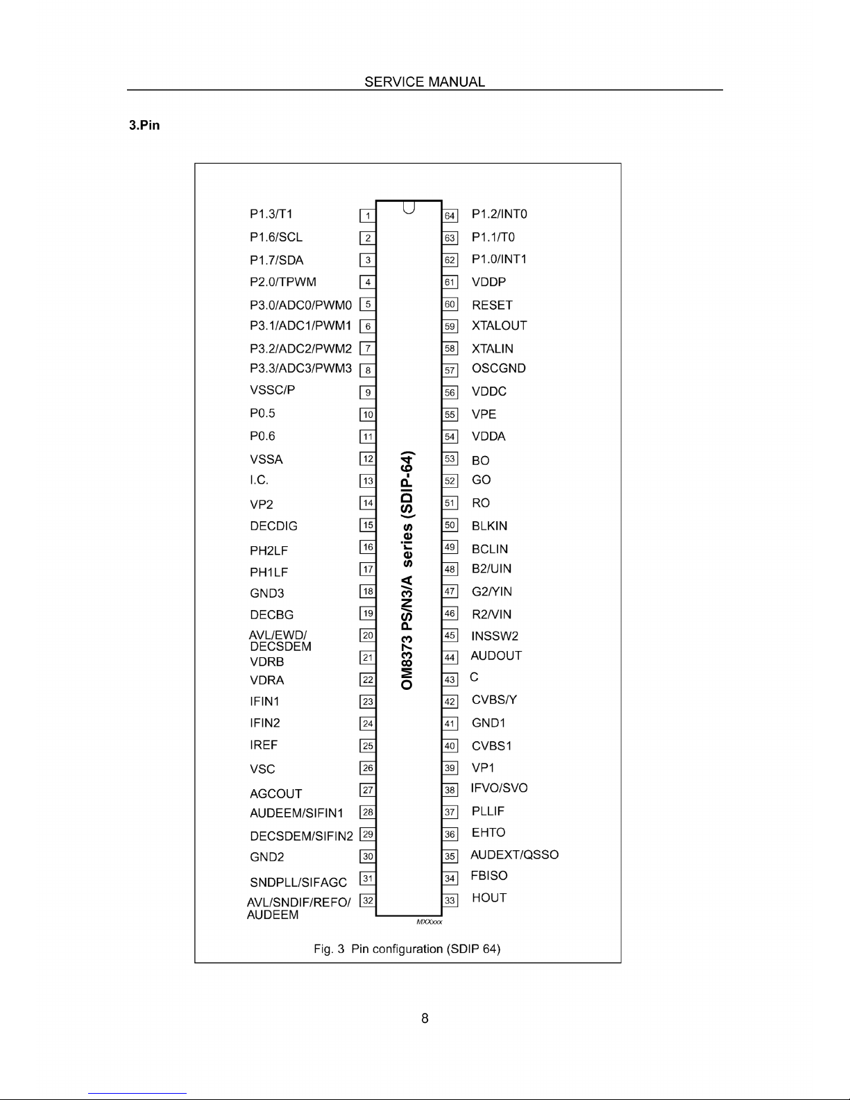
SERVICE MANUAL
9
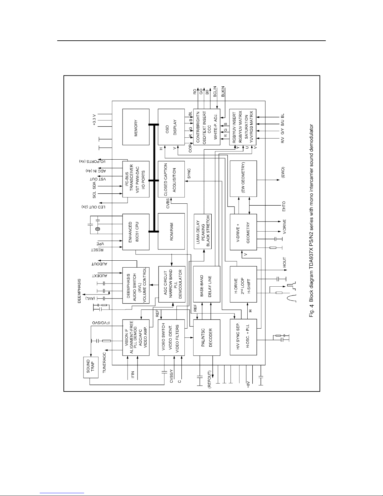
4.Block Diagram
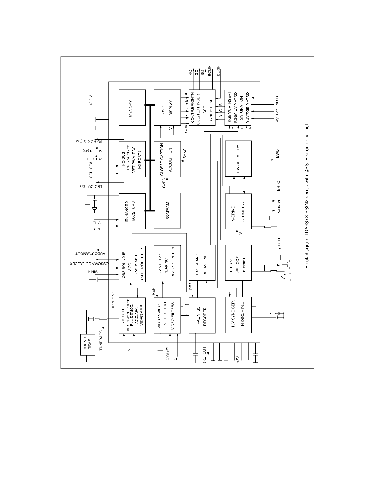
SERVICE MANUAL
10
5.Refer to T able 2 about Functions and Service Data of the IC’s Each Pin.
Fig. 5
SERVICE MANUAL
11
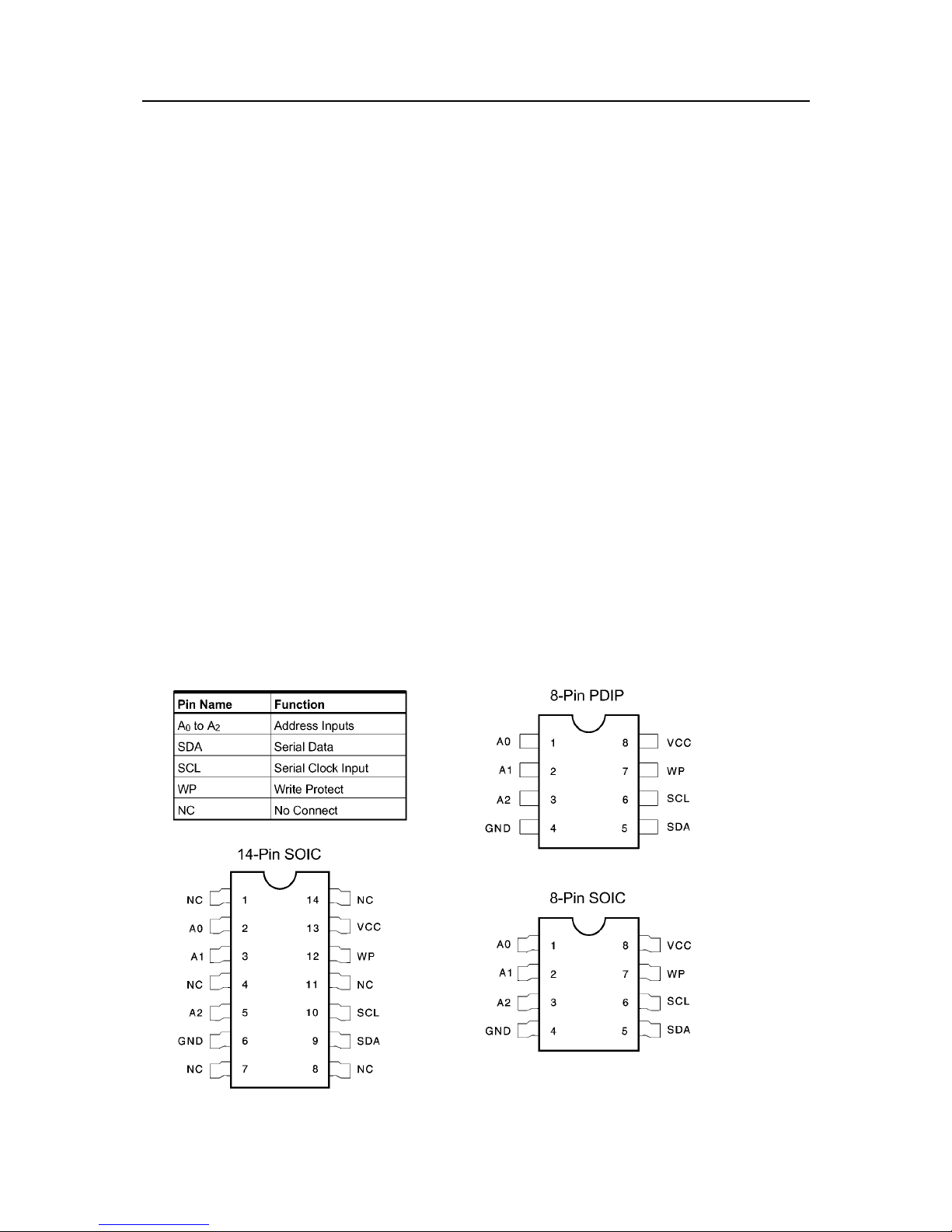
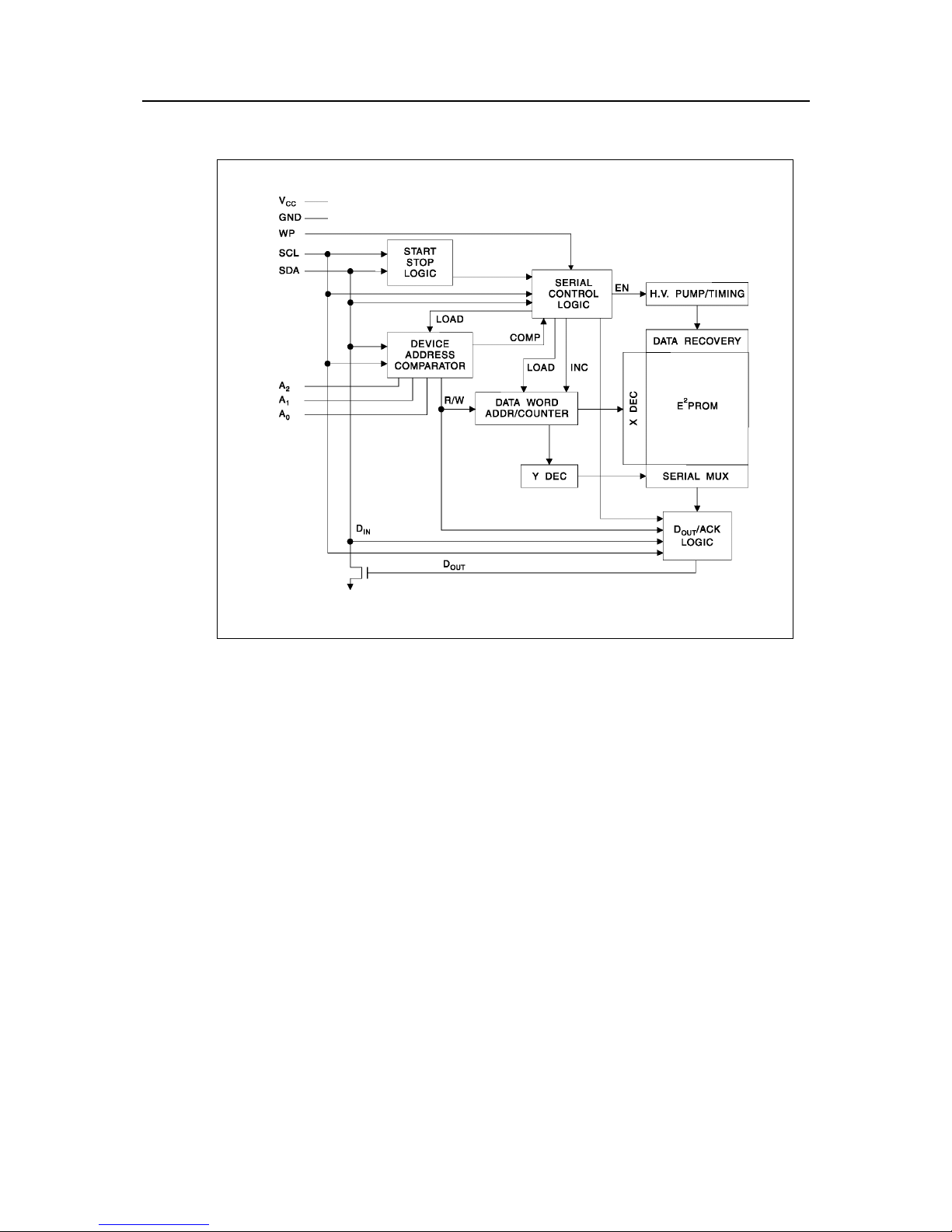
AT24C16 (N202)
EEPROM
1. Features
·Low Voltage and Standard Voltage Operation
5.0 (V
CC
= 4.5V to 5.5V)
2.7 (V
CC
= 2.7V to 5.5V)
2.5 (V
CC
= 2.5V to 5.5V)
1.8 (V
CC
= 1.8V to 5.5V)
·Internally Organized 128 x 8 (1K), 256 x 8 (2K),
512 x 8 (4K),1024 x 8 (8K) or 2048 x 8 (16K)
·2-Wire Serial Interface
·Bidirectional Data Transfer Protocol
·100 kHz (1.8V, 2.5V, 2.7V) and 400 kHz (5V)
Compatibility
·Write Protect Pin for Hardware Data Protection
·8-Byte Page (1K, 2K), 16-Byte Page (4K, 8K,
16K) Write Modes
·Partial Page Writes Are Allowed
·Self-Timed Write Cycle (10 ms max)
·High Reliability
Endurance: 1 Million Cycles
Data Retention: 100 Years
·Automotive Grade and Extended Temperature
Devices Available
·8-Pin and 14-Pin JEDEC SOIC and 8-Pin PDIP
Packages
2.Description
The AT24C01A/02/04/08/16 provides
1024/2048/4096/8192/16384 bits of serial
electrically erasable and programmable read
only memory (EEPROM) organized as
128/256/512/1024/2048 words of 8 bits each.
The device is optimized for use in many
industrial and commercial applications where low
power and low voltage operation are essential.
The AT24C01A/02/04/08/16 is available in space
saving 8-pin PDIP, 8-pin and 14-pin SOIC
packages and is accessed via a 2-wire serial
interface. In addition, the entire family is
available in 5.0V (4.5V to 5.5V), 2.7V (2.7V to
5.5V), 2.5V (2.5V to 5.5V) and 1.8V (1.8V to
5.5V) versions.
Pin Configurations
SERVICE MANUAL
12
3.Block Diagram
Fig.6
4.Refer to T able 3 about Functions and Data of the IC’s Pins.
SERVICE MANUAL
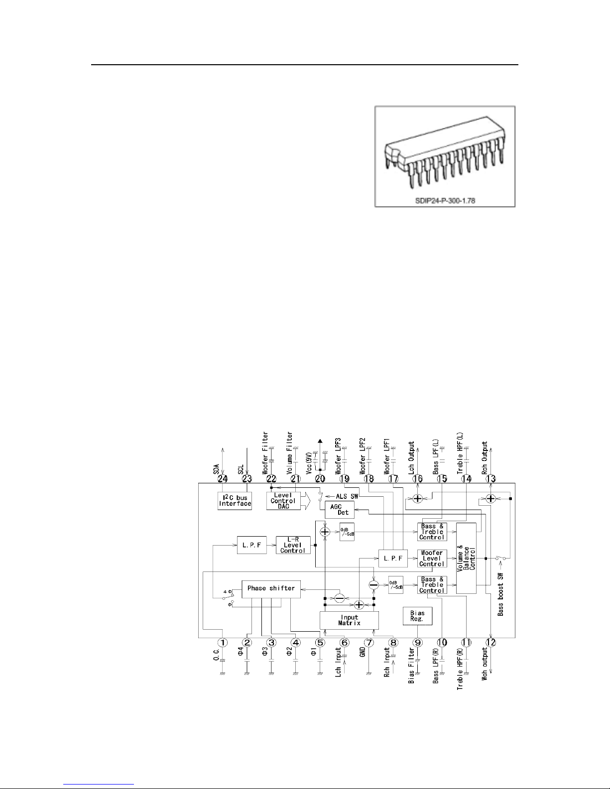
TA1343N
TV Sound Processor
TA1343N is a sound processor controlled by I2C
bus. It
incorporates the following: 2-channel input,
3-channel output
signal processing circuit, phase shift circuit for
surround, and LPF for woofer channel.
ALS (Automatic Level Suppresser) circuit which
prevents distort
Weight : 1.22g (Typ.)
the signal in large signal condition for woofer
channel is also
incorporated
1. Features
Surround circuit
Phase shift surround system
2 modes stereo surround
Pseudo stereo mode
Sound processing circuit
2ch inputs (Lch, Rch)
3ch outputs (Lch, Rch, Wch)
Input matrix switch
Volume control
Bass, treble, and balance adjustment
Woofer level and surround effect level adjustment
ALS (Automatic Level Suppresser) circuit
Built-in LPF for bass boost
2. Block Diagram
Fig.7
13
 Loading...