

Page 1
Sichuan Changhong Electric Co., Ltd.
Add: 35 Mianxing East Road, High-tech Zone, Mianyang, Sichuan, China.
Changhong Laser Display: laser.changhong.com
Changhong Official Website: www.changhong.com
J U N 0 . 0 1 8 . 2 6 1 2 V 1 . 0
Laser Projector
Fo r Ed uc at io n/ Co rp or at ion I ns ta ll at io n
P l ea se r ea d ca r e f u l l y b ef or e us i n g
Page 2
1. Packaging Overview
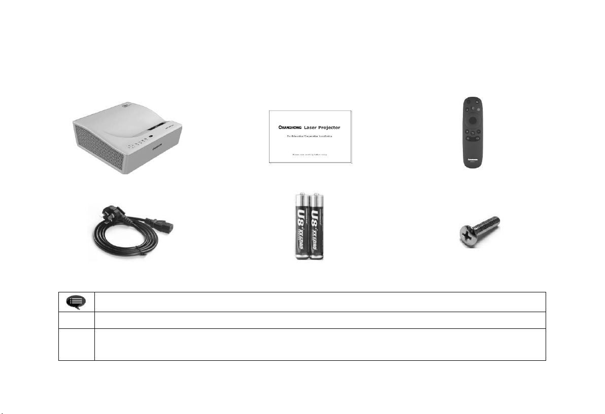
The packing box of this machine contains the following items. Please check carefully whether the following items are complete. If there are any
missing items, please contact your local distributor.
Main Unit × 1
Product User Manual × 1
Remote Control × 1
Power Cord × 1
① Please note that product accessories may be increased or decreased due to product upgrades
②
1
Due to differences in product application in each country (region), the product accessories may vary in some countries
(regions)
AAA Battery × 1
Prompt Information
Lifting Screws × 4
Page 3
2. Product Introduction
2.1 Product Specification Parameters
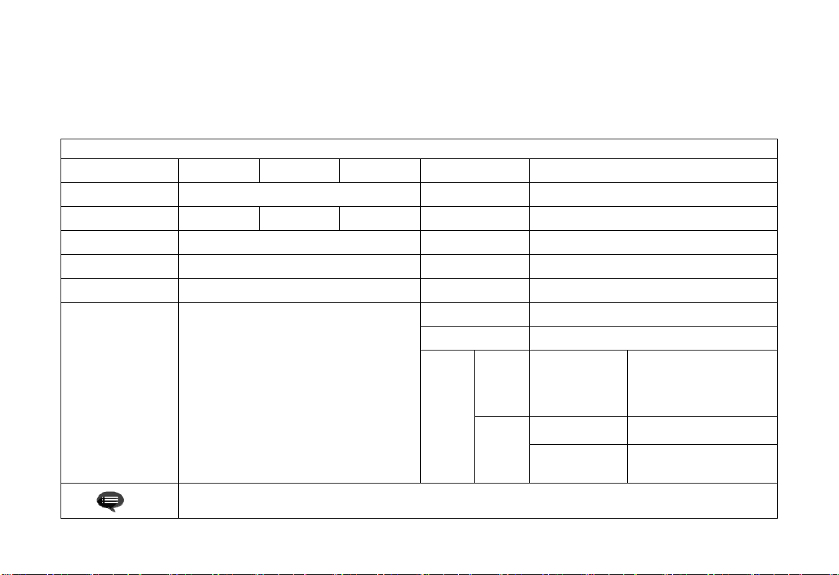
Product Specification Parameters
Product Model E5X36 E5W36 E5F36 Movement System Android Intelligent Movement
Display Technology
Resolution 1024×768 1280×800 1920×1080
Picture size 90''~135'' Built-in speakers
Sound Amplification 15w Implementation Q20541230-8.154-2019
Standby power ≤0.5W
Port
Laser light source + DLP technology Network
Image correction Yes
Network Port × 1 Analog Audio × 1
AV Input × 1 VGA Input/Output× 1
Digital Audio × 1 USB × 1
HDMI × 2 Factory Debug× 1
RS-232× 1 Audio Input × 1
VGA Input × 1
This device contains a radio transmission module with model approval code: CMIIT ID:2016AP1162
Power Supply
Body size
Net weight of main
Run
Environ
ment
Storage
Wired network + wireless network
5W×1
AC 110-240V,50/60Hz
381mm×382mm×147mm
8Kg
Temperature 0~35℃
Relative
humidity
Temperature ﹣20~50℃
Relative
humidity
20%~80%
20%~80%
2
Page 4
2.2 Appearance
2.2.1 Main Unit Structure
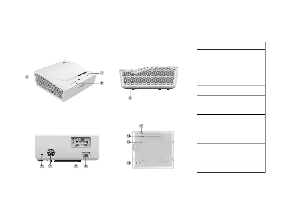
Figs. 1 to 4 below show the structure of the unit.
Fig. 1 45° left top
Fig. 3 Rear
3
Fig. 2 Right
Fig. 4 Bottom
Main Unit Structure
No. Name
①
②
③
④
⑤
⑥
⑦
⑧
⑨
⑩
⑪
⑫
Ventilation mesh
Control panel
Projection window
Ventilation mesh
Anti-theft lock hole
Built-in speaker
Port
Power jack
Anti-theft lock catch
Kickstand
Lifting hole
Kickstand
Page 5
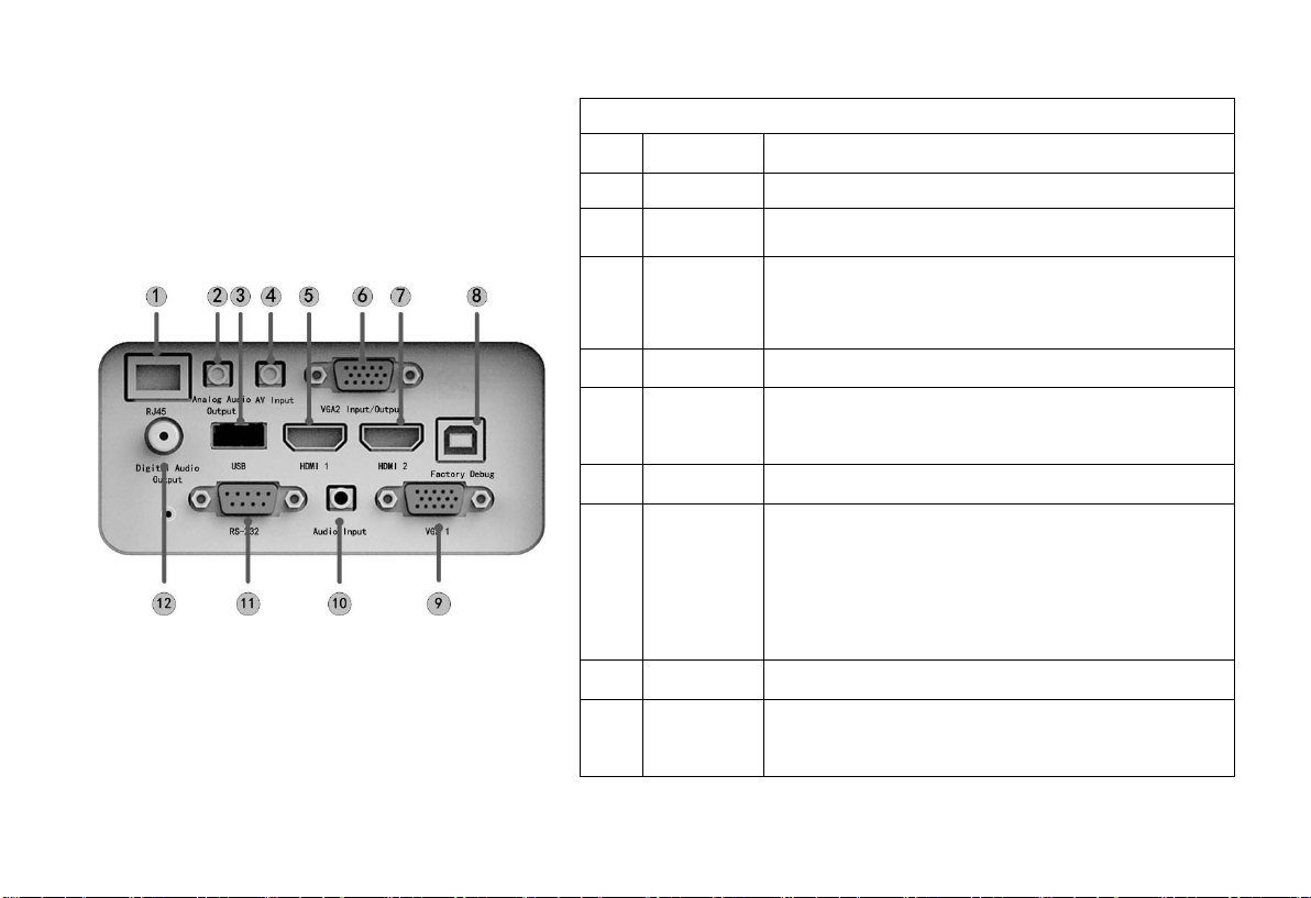
2.2.2 Ports
Fig. 5 Port
No. Name Function
①
②
③
④
⑤
⑥
⑦
⑧
⑨
⑩
⑪
⑫
Network
Analog audio
output
USB
AV input
HDMI1
VGA2
input/output
HDMI2
Factory
Debug
VGA1
Audio Input
RS-232
Digital audio
output
For wired network connections
Provide output of analog audio signal (L/R)
For connection with USB devices, such as flash disk, mobile
hard disk drive, etc.
For connection with audio/video equipment, such as DVD,
etc.
For connection with external devices with HDMI ports
For connection with personal computers or other devices with
VGA ports. This port is an input/output multiplexing port and
can be set through OSD menu
For connection with external devices with HDMI ports
For factory commissioning tooling only, do not insert any
signal wires
For connection with computers or other devices with VGA
ports (input ports)
Analog audio output for connecting audio and video playback
equipment
Application of System Integrated Control
The "coaxial output" mainly provides the transmission of
digital audio signals and can be connected to an external
sound system
Port
4
Page 6
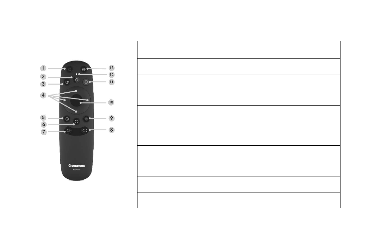
2.2.3 Remote Control
Fig. 6 Remote Controller
No.
①
②
③
④
⑤
⑥
⑦
⑧
Keys and Functions
Name Function
Power key Standby state switch
Home key
Watch Key Open umax
Up/Down/Left/
Right
Shortcut key Call up the display settings menu
Return key
Volume + key Volume Down
Volume + key Volume up
Short press this key to call up the main scene;
Long press this key to turn on/off the projector light source
When a menu is displayed, it is menu Up/Down/Left/Right;
When the media plays without menu, the function defined by is
executed
Press this key to return to the previous program/signal source;
Return to the previous menu;
5
Page 7
3. Installation and Commissioning
3.1 Installation
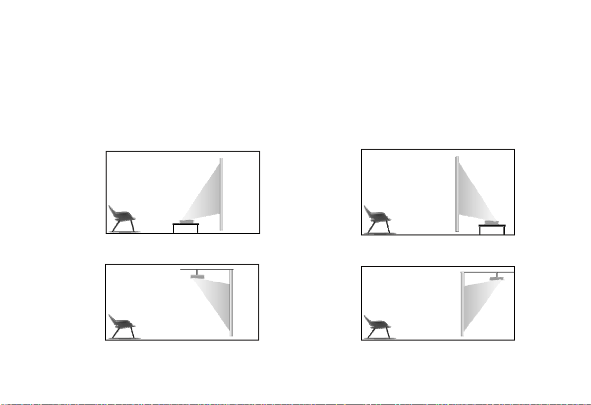
According to different application scenarios, the machine supports four installation methods: desktop front projection, desktop back projection,
lifting front projection and lifting back projection.
3.1.1 Installation Method
When changing the installation mode, the display mode (front desktop, rear lifting, front lifting and rear desktop) needs to be changed and set
from the OSD menu.
Fig. 9 Desktop Front Projection
Fig. 11 Lifting Front Projection Fig. 12 Lifting Rear Projection
Fig. 10 Desktop Rear Projection
6
Page 8
3.1.2 Screen Size and Installation Distance
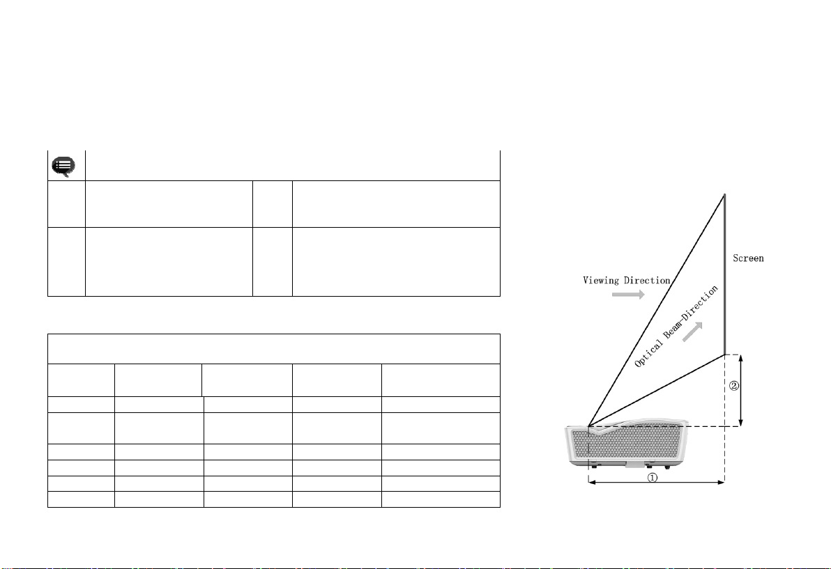
The distance between the main unit and the screen is proportional to the image size. The closer the main unit is to the screen, the smaller the
image size will be; vice versa. The following is a brief description of the relationship between screen size and installation distance, with the desktop
front projection as an example. Please refer to the following data to determine the approximate installation distance.
"① " in Fig. 13 is the distance
①
between the back end of the
main unit and the screen
It is suggested that the viewing
distance should be more than
③
1.5 times of the diagonal length
of the screen
Prompt Information
"②" in Fig. 13 is the height of the top of
②
the main unit relative to the bottom of the
screen
The under data are for users' reference
④
only. Please be noted that there may be
deviations in actual use
Screen size and installation distance (E5X36) Unit: mm
Screen
Size
70'' 1422 1067 428 160
80'' 1626 1219 484 183
90'' 1829 1372 542 206
100'' 2032 1524 605 229
110 '' 2235 1676 652 251
120'' 2438 1829 712 274
135'' 2743 2057 791 309
7
Width of
Display Area
Height of
Display Area
Projection
distance ①
Height from main unit
to screen ②
Fig. 13 Installation distance
Page 9
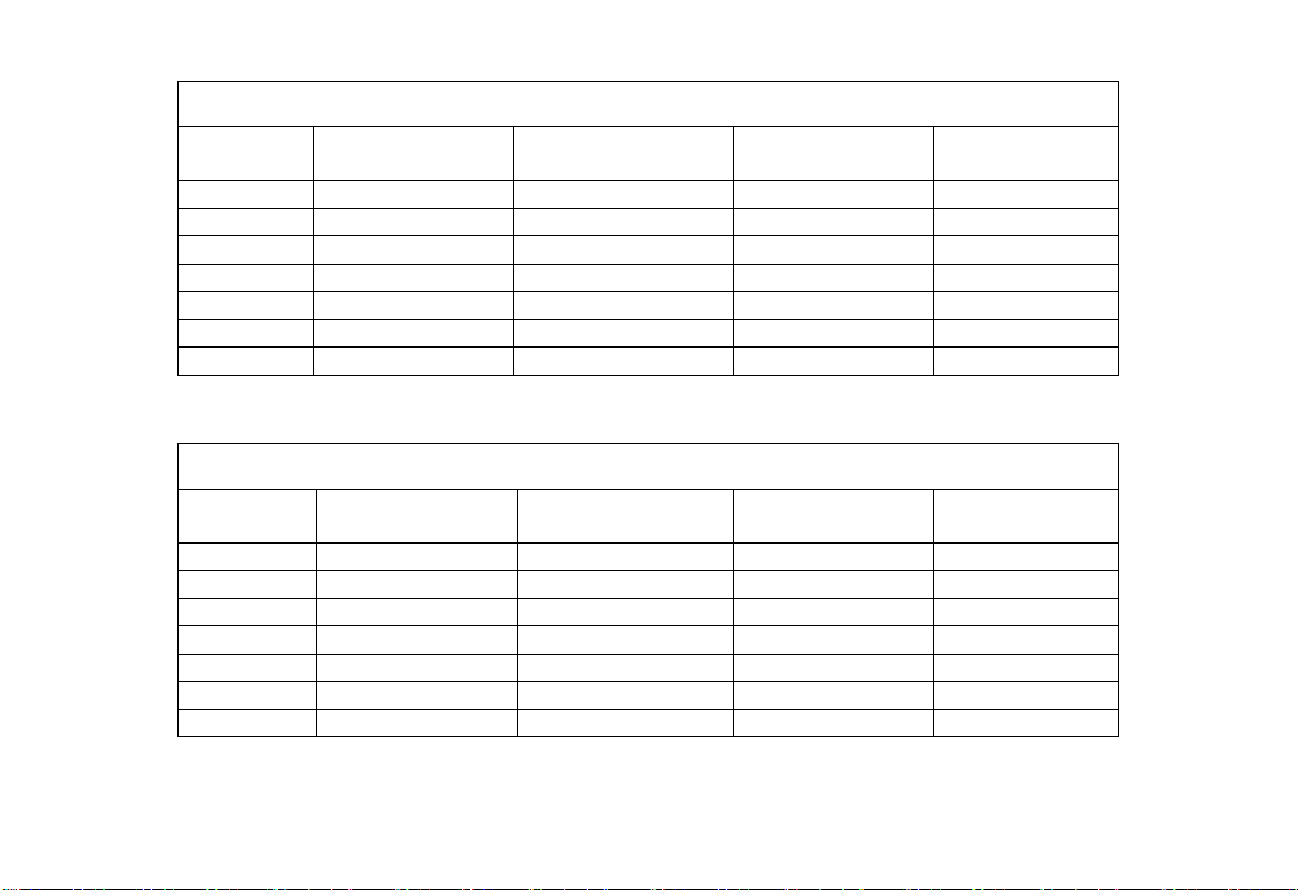
Screen size and installation distance (E5W36) Unit: mm
Screen Size Width of Display Area Height of Display Area
70'' 1508 942 351 141
80'' 1723 1076 402 161
90'' 1938 1211 452 182
100'' 2153 1346 502 202
110'' 2369 1481 552 222
120'' 2584 1615 602 242
135'' 2908 1817 678 273
Projection distance①
Height from main unit
to screen②
Screen size and installation distance (E5F36) Unit: mm
Screen Size Width of Display Area Height of Display Area
70'' 1550 872 361 153
80'' 1771 996 413 174
90'' 1992 1121 464 196
100'' 2214 1245 516 218
110'' 2435 1370 567 240
120'' 2657 1494 619 262
135'' 2989 1681 696 294
Projection distance①
Height from main unit
to screen②
8
Page 10

3.2 Picture Adjustment
3.2.1 Adjust Image Position
This section takes the installation method of desktop front
projection as an example to explain the picture adjustment for
users' reference.
a. Connect the power supply and start the main unit;
b. According to the picture display, adjust the size and position of
the picture by moving the main unit forward, backward, left
and right or rotating the height adjustment kickstand.
3.2.2 Focus Adjustment
a. Call out the electric focusing screen through the user menu: long
press the "Menu" key of the remote controller → select Display
Setting → select the Electric Focusing;
b. Adjust the focal length by pressing the "Left/Right" key of the
remote controller until the picture becomes clear from blur.
9
3.2.3 Image Correction
E5F36:
a. Long press the "Menu" key of the remote controller → select
Display Settings → select Image Correction to enter the Image
Correction menu;
b. Select the position to be corrected through the
"Up/Down/Left/Right" key of the remote controller and press
the "OK" key;
c. Adjust vertically through the "Up/Down" key of the remote
controller and horizontally through the "Left/Right" key;
d. After completing the correction of one position, press the
"Return" key, and then repeat the operations of b and c until the
correction of the whole picture is completed.
E5X36 and E5W36
a. Long press the "Menu" key of the remote controller → select
Display Settings → select Image Correction to enter the Image
Correction menu;
b. When the picture is narrow at the top and wide at the bottom,
press the "Left" key to correct, and when the picture is narrow
at the bottom and wide at the top, press the "Right" key to
correct;
c. According to the distortion of the picture, use the "Left/Right"
key to make geometric correction until the picture becomes
square.
Page 11
4. Operating Instructions
4.1 Basic Settings Menu
a. Under the program source and local media, press the "Menu"
4.2 System Home Page
key to open the "Settings" menu, and press the "Up/Down"
key to cycle through the adjustment items of the first-level
menu, and press the "OK" key or the "Right" key to enter the
next-level menu. When any parameter adjustment option is
selected, press the "OK" key to confirm the selection or enter
for adjustment, and then use the arrow key and the "OK" key
to adjust.
b. Under any scene, long press the "Menu" key to call up the "All
Settings" menu, and press the "Up/Down" key to select
various menus, and then press the "OK" key to enter;
c. The parameters such as sound, image, network, system, etc.
can be set in the "Settings" and "All Settings" menus;
d. After completing the required operations, press the "return"
key to return to the previous menu interface step by step, or
press the "Menu" key to exit the menu directly.
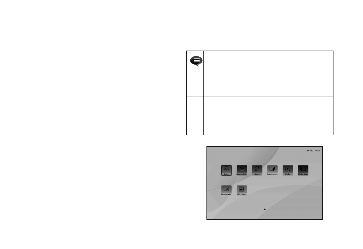
a.Short press the "Home" key to enter the "Main Scene
" interface;
b. There are submenus such as Settings, Memory Optimization,
Program Source, TV Manager, Personalization, Weather, Media
Center, Multi-Screen Interaction, App Lock, Display Settings,
WPS Projection, etc. under the home menu, which can be
Some options in the user's operation interface are not
selectable, displayed or hidden automatically in different
①
models, signal sources or states
The user operation interface can be updated through
software upgrade. If there is any difference between the
②
user manual and the final product, the actual display shall
prevail
Prompt Information
Fig. 14 System Home Page
10
Page 12
5. Safety Precautions
This machine contains a laser module. For your safety, please follow the following tips.
Do not look directly at the bright light emitted by this machine, otherwise it
①
may cause eye injury
Do not open or disassemble the machine, which may cause damage due
②
to exposure to laser radiation
Do not use some optical instruments (such as magnifying glass and
③
microscope for experiments) to observe the laser output, otherwise eye
injury may be caused
Wear professional laser protection glasses when there is a need to have
④
direct contact with bright light
Appropriate instructions for assembly, operation and maintenance,
including preventive measures and clear warnings to avoid possible
⑤
exposure to laser light and accompanying excessive radiation reaching
Class 1 emission limits
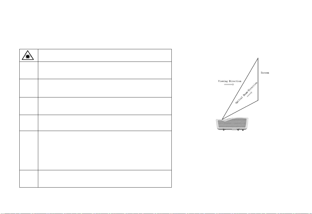
⑥ For your safety, please select the right viewing direction
Precautions
Prompt Information:
- Conforming to Class 3B laser equipment conforming to 60825-1:
2014(Third Edition)
Fig. 15 Viewing Direction
.
11
Page 13
①
②
③
④
⑤
⑥
⑦
⑧
⑨
⑩
⑪
⑫
Precautions
Do not place the machine near heat sources such as direct sunlight, radiator, fire or stove
When the machine is moved from a low temperature environment to a high temperature environment, condensation may occur
inside the machine. Please do not use it immediately
In case of any abnormality or malfunction, such as no image, no sound, smoking or unusual odor, please disconnect the power
supply immediately, unplug and contact our after-sales service personnel to start the machine for inspection
Do not block the air vent and install the machine in a well-ventilated place to prevent the machine from overheating
Do not use flammable materials such as books and cardboard to block the light beam emitted by the machine. Flammable
materials may melt or ignite objects or even cause fire when exposed to the light beam for a long time
Do not place the machine directly in areas with poor ventilation such as carpets, cushions, bookshelves or closets.
To facilitate ventilation, please ensure that the distance between the ventilation opening of the machine and the wall is greater
than 30cm
Do not place flammable spray or other flammable substances beside this machine
If there is a gas leak, please do not touch or switch the wall socket. Open the window immediately for ventilation
Do not touch or wipe the lens with hands or ordinary cleaning cloth. To remove dust from the lens, please use an ear syringe ball
When installing the machine by hoisting, professional technicians shall use corresponding professional tools for installation.
Improper installation may cause the machine to fall, thus causing personal injury or damage to the machine
Please contact your dealer or Changhong After-sales Service Center for inspection, adjustment or maintenance.
Non-professional operation may cause electric shock or damage to the machine
12
Page 14
6. Environmental protection statement
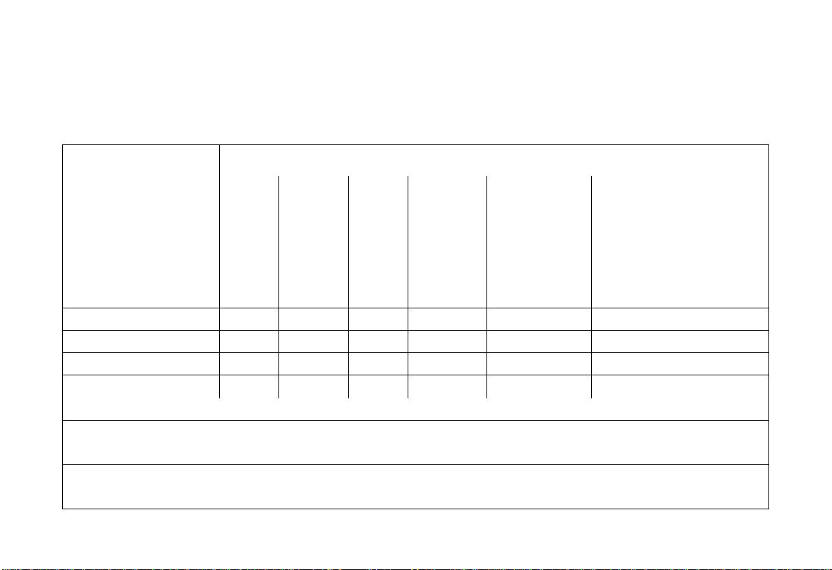
In order to realize cleaner production of products, improve resource utilization efficiency, protect the environment and human health, and
promote the sustainable development of the industry, the toxic and harmful substances in this machine are controlled according to the requirements
of Measures for Pollution Control and Management of Electronic Information Products. The relevant information is as follows:
Toxic and Harmful Substances or Elements
Lead
Part Name
Laser light source × ○ ○ ○ ○ ○
Circuit board assembly × ○ ○ ○ ○ ○
Optical machine assembly × × ○ ○ ○ ○
Power Switch ○ ○ × ○ ○ ○
Remote Control × ○ ○ ○ ○ ○
*: Circuit board components include printed circuit boards and their components, such as resistors, capacitors, integrated circuits, etc.
○: indicates the content of the toxic and harmful substance in all homogeneous materials of the component is below the limit specified in the
standard of GB/T26572
×: indicates that the content of the toxic and harmful substances in at least one homogeneous material of the component exceeds the limit
requirements specified in the standard of GB/T26572
and its
Compou
nd
Mercury
and its
compound
s
Cadmiu
m and
its
compou
nds
Hexavalent
chromium
compound
Polybrominated
biphenyls (PBB)
Polybrominated diphenyl ether
(PBDE)
13
Page 15
Note: The reason why the content of toxic and harmful substances or elements in the above-mentioned product components exceeds the
limit specified in the standard is that there is no fully mature substitute for the time being due to the limitation of current industry technology
and technological level
It indicates that the environmental protection service life of the product is 10 years under normal working and using
In order to protect the environment, used batteries and products can be recycled by regular dealers or manufacturers.
It indicates that packaging materials can be recycled, please do not discard them at will
conditions, and the product can be used safely within the environmental protection service life
Please do not discard them at will
14
Page 16

7. Warranty Service
Dear user,
Thank you for your favor to CHIQ products! Please fill in the warranty card
timely and accurately to ensure that you can get better service after purchasing the
product. In the future using process, if there is product failure or you have any
comments/suggestions, please contact us through authorized local dealers:
Or you can reach us directly by visiting our website: laser.changhong.com
About after-sale service including installation, service and maintenance, the
local country laws and authorized local dealer’s policy shall prevail.
Regards,
Sichuan Changhong Electric Co., Ltd.
Please paste the purchase invoice and local dealer’s warranty service
guarantee terms card here.
Warranty
a. During the warranty period, if there is any fault caused by the product
quality issues, you can enjoy maintenance service with the completed
service warranty card and purchase invoice.
b. Please properly keep the service warranty card and the purchase invoice
as the warranty certificate.
c. The warranty will automatically become invalid once the service warranty
card and the purchase invoice are altered.
d. Matters not covered shall be implemented with reference to relevant
national laws and regulations or industry regulations.
Under any of the following circumstances, the warranty service will not be
applicable, and you will be provided with charged maintenance services:
a. Exceeding the validity period.
b. Damage caused by improper use, maintenance and storage.
c. Damage caused by dismantling by unauthorized persons.
d. Lack of warranty card and invoice (unless the product can be proved that
it is within the validity period).
e. Altering the warranty card without authorization.
f. The product model or number of the warranty card does not conform to
the actual goods.
In case of any changes in the list above, the newly formulated relevant
regulations of the company or the relevant laws and regulations updated by
the country shall prevail.
15
Page 17
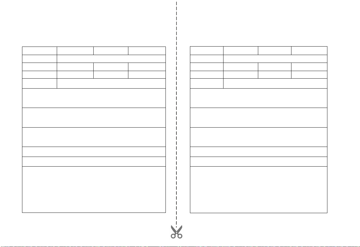
Warranty Card Warranty Card
n
Date of Installation: _____/_____/_____ Date of Installation: _____/_____/_____
User name Tel
Address
Machine model Shopping mall
Invoicing date Invoice No.
Body barcode
Service Status: □ Screen Installation and Commissioning □ Mount Installation
and Commissioning □ Separate Onsite Debugging
Please confirm the wall properties for screen installation: □ Solid Brick Wall
□ Hollow Wall Brick □ Wooden Wall □ Other
The appearance of the machine and the electrical performance are in good
condition after installation: □ normal □ abnormal
User Satisfaction Survey: □ Satisfied □ Not Satisfied
User signature:
The first copy is retained by customer (warranty card)
User name Tel
Address
Machine model Shopping mall
Invoicing date Invoice No.
Body barcode
Service Status: □ Screen Installation and Commissioning □ Mount Installatio
and Commissioning □ Separate Onsite Debugging
Please confirm the wall properties for screen installation: □ Solid Brick Wall
□ Hollow Wall Brick □ Wooden Wall □ Other
The appearance of the machine and the electrical performance are in good
condition after installation: □ normal □ abnormal
User Satisfaction Survey: □ Satisfied □ Not Satisfied
User signature:
Authorized Dealer Information
Authorized Dealer Information
The second copy (retained by authorized dealer)
16
Page 18

17
 Loading...