

Page 1
MODEL
CM491
BUTTON SEWING MACHINE
PARTS
BOOK
Page 2
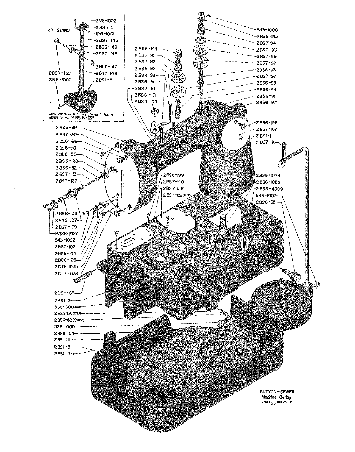
471
STAND
2BSI
-4,,,,~-
BUTTON-
Machino
CHANOL£R
=
SEWER
Outlay
lofACIQIE
co.
Page 3
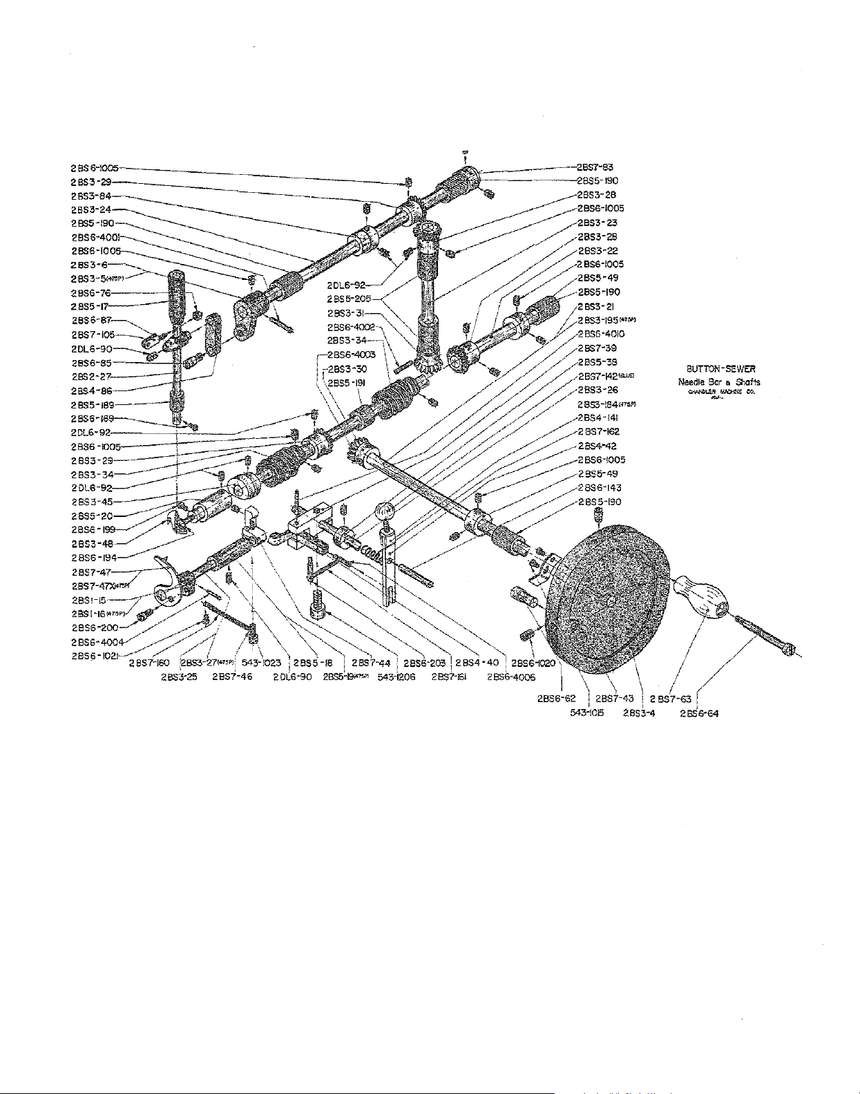
BUTTON-SEWER
Needle Bar a
C<\ONili..ER~ee>.
Shotts
-
Page 4
Page 5
~----·--:
54,:->r>nn-__;_--;~
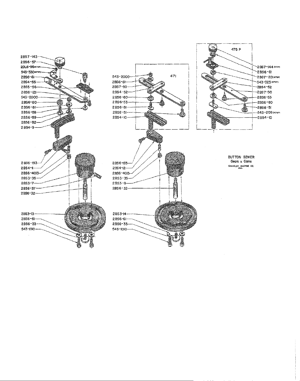
471
I
BUTTON
SEWER
Geors a Corns
Page 6
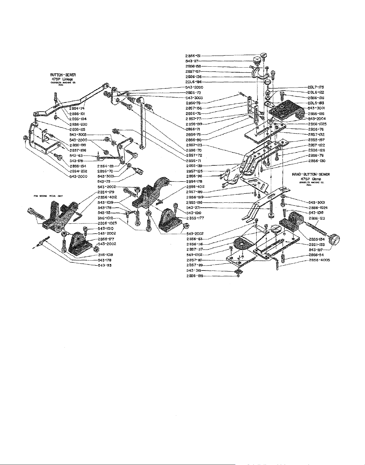
SUTTON-
SEWER
475P
Linkage
t:M~""">lMI».
-
Page 7
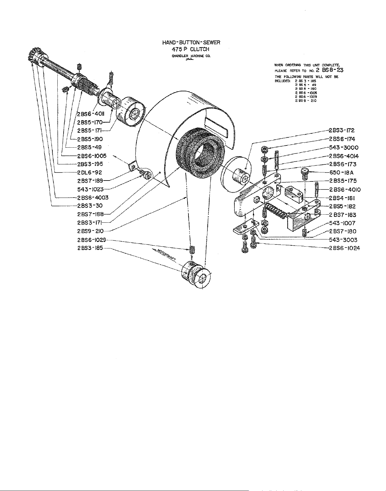
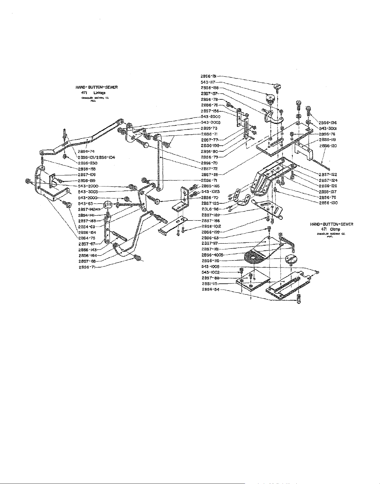
HAND-BUTTON-SEWER
475 P CLUTCH
Q.lAKILER
MACHINE
CO.
-
WI-EN
ORDERING
PLEASE REFER TO
THE
FOLLOWING
INCLUDED: 2 6S
2BS5-49
2BS5~tso
2 BS6 -1005
2
BS6
28$9-210
nns
NO.
PARTS
3 ~ 185
-1029
UNIT
COMPLETE,
2
BS 8-23
WILL
NOT
BE
-1024
Page 8
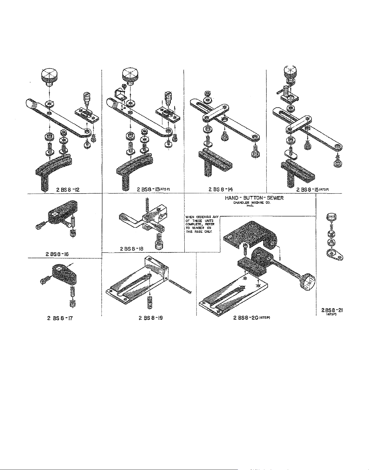
2 BS8
2 BSS-16
2
BSS-17
-12
2BSS-J9
WHEN
OAD£RING
Of
THESE
COMPLETE,
TO
NUMBER
THIS
PAGE
2BSS-J4
HAND
- BUTTON-
CHANDLER
AlN
,.-----~------------!
UNITS
REFER
ON
ONLY.
2
MAO-liNE
......
BS8-20<475P)
SEWER
CO
•
2
BSS-15'"''~
Page 9

28SS-I
WHEN
ORDERING
COMPLETE,
AAGE
ONLY.
BS
2
BUTTON-
OfANDLER
REFER
#rf
TO
8-2
MACHINE
=
o;::
THESE UNITS
NUMBER
SEWER
CO.
ON
THIS
2
BS
8-3
2858-4
2
BSB-5
2
BSB-
6
2
BS
8-8
2
BS
8-9
2 BSB-10 2
858-11
Page 10

HAND BUTTON SEWER
475P
Please note:
Chandler
472, 475P & 485P
Models 401, 461, 471, 481,
are
also represented in this book.
Page 11

WHEN
ORDERING
ANY
OF
2 BS 8-24 (475P)
THESE
THIS
UNITS
PAGE
COMPLETE,
ONLY.
REFER
TO
NUMBER
ON
2 BS 8-25 (475P)
Page 12

USE
THIS
COMBINATION
EYE
GUARD.
SCREW
TO
FINGER
ATTACH
AND
Page 13

2BS4-55
21856-59
21356-136
21BS7-128
543-2000
2BS6-61
2BS6-82
HAND BUTTON
Side
Vibrotion Mechanism Revision
Class 481 and
SEWER
485-
P
Page 14

INSTRUCTIONS
FOR
INSTALLING
472 & 475P & 485P
CLUTCH
UNIT
ON
Refer to
With
approximately 3/8", the clutch assembly is positioned on clutch
stop
be tightened
run
stop blade, should be
position,
Any
needle
shaft
the
adjustments
bar
is relieving tension from
on
machine
and
the
in highest
flat
of
thru
under
pulley should be free
for this should be made
or
stop position,
shaft
one cycle by hand.
and
leading
parts
the
Allen screw on bottom is also tightened.
end
book
clutch, allowing pulley to spin freely.
When
of
of
the
by
re:
part
numbers
and
stop
shaft
stop
shaft
stop
shaft,
clutch, with a minimal
moving stop
2BS3-184
is activated,
the
needle
shaft
protruding
shaft
bar
amount
in
or
2BS3-195 so
With
part
No. 2BS-7180,
should
out
be
which is governed
that
Cap
screw will
power off,
in its highest
of
clearance.
the
by the collar inside the machine.
the
stop
clearing
shaft
by approximately
With
the
machine running,
1/32
of
an
inch.
the
stop
blade
should be
Page 15

MAIN office
131 W. 25th Street
New York,
Tel: 212-741-7788
Fax: 212-741-7787
NY
10001
Miami.FL
4013 N.W. 79th Avenue
Miami, FL 33166
305-471-0200
Tel:
Fax: 305-471-0243
Los Angeles. CA
2320 South Hill Street
Los Angeles,
Tel: 213-745-8844
Fax: 213-745-8855
CA
90007
Page 16

f,.C.INt
il
IN'®
CONSOLIDATED
MODEL
SEWING
DCS-S3
MACHINE
CORP.
LEATHER
PARTS
SKIVING
BOOK
MACHINE
Page 17

1. PRESSER
~
'
.a---
~
FOOT
8
,.
23
24
•
AND OUTER ATTACHMENTS
I~
~
0
0 0
0
0
2
3
•
8
--------·-··
~
...
53
0
()
51
50'---~
1
Page 18

Item
No.
Part
No. Description
1-1
1-2
1-3
1-4
1-5 1153
1-6
1-7
1-8
1-9
1-10 1004
1-11
1-12
1-13
1-14
1-15 1132
1-16
1-17 1007
1-18
1-19
1-20 1086
1-21
1-22 1140
1-23
1-24 1628
1-25 3163
1-26
1-27 1122
1-28 9634
1-29
1-30 1008
1-31
1-32
1-33
1-31
1-35
1-36
1-37 1563
1-38
1-39
1-40 1002
1-41
1-42
1-43
1-44
1-45 1009
1-46
1-47
1-48
1-49
1-50 1105
1157
1156
28156
1316
1155
1150
1151
1145
11/64
31628
31628-10
1144
1140
1001
1085
1152
1625
1141
1009
1006
4096
4097
1003
1004
1005
6254
1562
1036
1036-40
1037
1038
2001
2002
2002-16
2002-30
Presser
Presser
Presser
Presser
Presser
Presser
Presser
Presser
Presser
Presser
Presser
Presser
Presser
Presser
Presser
Presser
Oil
Arm
Presser
Presser
Presser
Presser
Inner
Taper
Presser
Presser
Worm
Flat
Ruler
Ruler
Ruler
Slide plate screws (6)
Slide plate screws (2)
Slide plate A
Slide plate B
Slide plate C
Waste feeder screw
Waste feeder stop
Hex
Bed
Belt cover plate
Belt cover
Belt cover lid
Belt cover lid
Ruler
Hinges (2)
Hinge pins (2)
Hinge screw washers (4)
Hinge screws (4)
Waste feeder metals (set)
bar
adjusting screw
bar
lifter
bar
lifter
bar
lifter
lifter
bar
lifter lever
bar
cover screw
bar
spring
bar
foot slide plates (2)
foot slide
foot slide
foot shaft
foot shaft
foot
shaft
loot 50
cap
foot adjusting screw
foot adjustable screw nuts (2)
bar
foot
hex
pin
foot
foot shaft
chamber
screw
set screw
set screw
head
set screw
2
mm
spring
spring
head
screw
spring
washer
slotted screws, base plate
plate
stopper
bracket
bracket
pin
plate
plate
hook
hook
shook metal screw
pin
screw
plate
pin
screw
(2)
screws
screws (
screw
metal hinge screw
metal set screw
4)
(2)
(2)
Page 19

2. KNIFE AND RELATED PARTS
3
ff?
51
62
53
i
64
24
23
25
28
31
32
28 29
:k)
40
41
4344
45
49
47
46 50 48
3
Page 20

Item
2-1 1021
2-2
2-3 1010
2-4
2-5 3013
2-6 81875 Knife
2-7
2-8
2-9
2-10 1033
2-11
2-12 428x16x75
2-13 9/32x28x4.5
2-14
2-15
2-16
2-17 3x16
2-18
2-23
2-24
2-25 1014
2-26
2-27 3x18
2-28 1017 Knife
2-29 1018
2-30 1020 Knife
2-31
2-32
2-33
2-34
2-35
2-36 1030
2-37 1049
2-38 1040
2-39
2-40 1024
2-41 1046
2-42
2-43
2-44
2-45 1160
2-46
2-47
2-48 9/64"x40x6
2-49
2-50
2-51
2-52 20x35x1
2-53
2-54
No.
Part
1610 Knife
1011
1023
1015 Pulley
1034 Flange shafts (2)
9/32x28x18
3x10
1031
M16pXP1.5
1020 Knife
1013
1016 Knife
6203Z
5/16"x24x21
1035
1043
W'x40
15/64x28x81
1041
1042 Clutch lever
9/64"x40x6
1039
NTB2035
6004 zz
6023 zz
No. Description
Leather
Knife
Knife
Knife
Rubber
Pulley
Pulley
Pulley
Pulley
Pulley
Pulley
Pulley
Hexagonal
Knife
Knife
Taper
Knife
pulley
pulley
Clutch
Pulley
Clutch
Clutch
Clutch
Clutch
Clutch
Clutch
Clutch
Clutch lever
Clutch
Clutch
Clutch
Clutch lever
Clutch
Truss
Flat
Bearing
Bearing
peeler
set
screws (
shaft
shaft
key
shaft
nuts
bushings (2)
shaft
flange
shaft
flange
shaft
flange
shaft
flange screws (B) (2)
shaft
flange screws (A) (2)
shaft
key (small)
shaft
shaft
key (large)
nut
shaft
lead
shaft
lead
shaft
worm
shaft
worm
pin
adjusting
adjusting
adjusting
shaft
hearings
shaft
metal
slide
block
slide
block
arm
spring
spring
slide
block
lever screw
arm
server
lever
lever
lever
bearing
gasket
cover
4)
(2)
(A)
pipe
pipe
wheel
knob
handle
handle
hook
shaft
spring
spring
spring
spring
holder
nut
key
knob
screws (3)
screws (3)
screw
shaft
nut
hinge
hinge screw
screw
washer
4
Page 21

3. GRINDSTONE AND
ROLLER
RELATED PARTS
64
66
70
71
12
68
67
7.3
5
Page 22

Item
3-1
3-2
3-3
3-4
3-5
3-6
3-7
3-8
3-9
3-10
3-11
3-12
3-13
3-14
3-15
3-16
3-17
3-18
3-19
3-20
3-21
3-22
3-24
3-25
3-27
3-28
3-29
3-30
3-31
3-32
3-33
3-34
3-35
3-36
3-37
3-38
3-39
3-40
3-41
3-42
No.
Part
1116
1115
1119
1120
9/64"x40x90
1123
1117
121803
1123
2.5x10
1110
3x16
6002ZZ
M63xlOP1.5
1111
M14xP1.5
3
1051
1052
1050
1053
2.5x20
6200Z
1056
1055
1057
5/16x24
1731
1069
15/64x24x14
5/16x24x14
'lz"x28
1066
1058
1059
1063
626Z
1062
1063
No.
starK20
Description
Worm
Main
Main
Roller driving
Roller driving
Main
Main
Main
Main
Main
Main
Main
Main
Main
Main
Main
Hexagonal
Main
Grindstone set screw
Grindstone set screw
Grindstone
Grindstone shaft
Grindstone shaft pulley
Grindstone shaft bearings (2)
Grindstone shaft
Grindstone
Grindstone
Grindstone
Grindstone
Grindstone shaft
Grindstone shaft
Grindstone adjusting screw pipe
Grindstone adjusting screw pipe
Grindstone adjusting screw
Grindstone
Belt guide pulley screws (2)
Belt guide pulley shafts (2)
Belt guide pulley bearings ( 4)
Belt guide pulleys (2)
Belt guide pulley washers (2)
wheel box
shaft
worm
shaft
worm
shaft
shaft
shaft
worm
shaft
worm
shaft
front
shaft
worm
shaft
worm
shaft key (1)
shaft
shaft key (2)
shaft
bearing
shaft
bearing
shaft pulley
nut
B
shaft belt
shaft
shaft
shaft
shaft
shaft
gear
wheel
gear
metal (1)
metal (2)
gear
wheel screw
gear
chamber
bushing
gear
chamber
gear
chamber
holder
nut
taper
bracket
bearing
bracket
bracket
bracket
bracket
bracket
belt
screw
roller
arm
arm
arm
arm
arm
pin
center
center
spring
spring
cover screw
oil seal
screw
screw nuts
screws
screws
nuts
(2)
6
Page 23

Item
No.
Part
No.
Description
3-43 15/64x28x8 Belt guide pulley
3-44
3-45 3x18 Belt guide
3-46
3-47
3-48
3-49 1118 Roller driving
3-50 3x13 Roller driving
3-51
3-52 1094 Roller
3-53
3-54 Roller shaft oil scalping
3-55 1080 Roller
3-56
3-57 1083 Roller
3-58 15/64x28x10 Roller shaft screw
3-59
3-60 1098 Roller
3-61
3-62 1096 Roller
3-63
3-64
3-65
3-66
3-67
3-68
3-69
3-70 1088 Roller
3-71 1087 Roller
3-72
3-73 1089 Roller
3-74
3-75
3-76
3-77
3-78
3-79
3-80
3-81
3-82
3-83
3-84 Roller shaft screw
1060 Belt guide
1067 Belt guide
1061 Belt guide
1065
1121 Roller driving shaft
1081 Roller shaft
1082 Roller
11/64x40x3.5 Waste clear metal shaft screw
1095 Roller
1091 Roller
1092 Roller
1093 Roller
1097
1085 Roller
1086 Roller
1083 Roller
1090 Roller
l/4x20x20 Set screw (3)
1099
1100 Roller
9/64x10 Waste clear metal
1101 Waste clear metal
1104 Waste clear metal
9/64x40
1103 Waste clear metal spring
1102 Waste clear metal shaft
4x22
Belt guide
Roller
Roller
Waste clear metal
Taper
bracket
bracket
bracket
bracket
bracket
shaft
washer
bracket
bracket
bracket
bracket
bracket
bracket
bracket
bracket
bracket
bracket
bracket
bracket
bracket
bracket
bracket
bracket
bracket
pin
shaft
taper
spring
shaft
turn
shaft
shaft
oil wick
arm
arm
arm
arm
arm
arm
arm
turning
turning
turning
turning
turning
turning
turning
arm
arm
leather
leather
leather
key
joint
spring
spring
spring
adjusting
adjusting
spring
center
center
screws (2)
pin
stoppers
hooks (2)
hook
screw
screw
hooks (2)
arm
adjusting
arm
adjusting
arm
arm
spring
arm
spring
arm
spring
arm
spring
pin
pin
screw
nuts (2)
screws (2)
metal
nut
screw
screw
stopper
adjusting
adjusting
nut
nut
nut
screw
7
Page 24

4.
ACCESSORIES
(
([
«
7
0
<'
s,~;~l
\
A40mlm
8 31)mlm
C2Smtm
8
Page 25

Item
No.
Part
No.
Description
3-1 3001
4-2
3-3 3004
4-4
4-5
4-6
4-7
1-16A
1-16 B
1-16C
1-47 2002 Hinge pins (2)
1-36
1-48 15x6.3x1.6
1-39
2-29
2-30 1019
4-5
3002 Grindstone
3005
3006
3007
3008 Oiler
1130A
1140B
1140C
2001 Hinges (2)
6x30 Hinge set screws (4)
1018
3006
Grindstone dresser
spanner
Knife
Knife interior cover remover
Bar
Screwdriver (large)
Presser
Presser
Presser
Hinge set screw washers (2)
Knife adjusting handle
Knife adjusting handle
Bar
shaft
spanner
type grindstone
foot 50
foot 30
foot 25
type grindstone
mm
mm
mm
10
 Loading...