

Page 1
Model
CM101
INSTRUCTION
MANUAL &
PARTS
LIST
Page 2
1.
Unpacking
the
Machine
INSTRUCTION
INDEX
..........................................................
MANUAL
1
2. Setting-up
3.
Hand
4.
Oiling
5.
Replacing Needle
Threading
6.
7.
Inserting
8.
Adjustment
9. Stitch
10. Needle
11. Skip Stitch Device
12. Removal
Cloth
13.
14. Stitch Stabilizing
wheel
Length
Machine
Rotation
and
Maintenance
......•...........................................................
Machine
the
Work
of
Needle
Regulation
Recommendation
of
the
Work
Retainer
Spring
.................................................................
and
Speed
..........................................................
...............................................................
and
Starting
Penetration
.........................................................
........................................................
................................................................
from
Adjustment
Guide
..........................
................................................
to sew
the
Machine
.............................................
.......................................
....................................
...........................................
.,
..............................
1
1
1
2
3
4
4
5
5
6
6
7
7
Page 3
1.
Unpacking the Machine
Open
parts
Small accessory
materials
Clean
mechanism
packing
which
from machine all grease,
box
project
parts
without
and
looper.
by
carefully removing its cover so as
from
the
are
packed
prior
scrutiny
2. Setting-up the Machine
Assemble knee lifter lever to machine
from
the
front
edge
of
the table. Line
3.
Hand
groove
sewing table
The
motor
for a brand
weeks
increased
of
drive mechanism
and
place felt
wheel Rotation
hand
wheel should
drive is set
new machine is 1,800 to 2,000 stitches
and
after
the
up
to 2,500 stitches
up
to
operator
rotate
operate
and
top, such as
separately
as to contents.
dirt
(motor
pad
under
Speed
away
in
the
has
become skilled in
per
minute.
the
tension
in
individual packages. Do
or
dust.
Pay
particular
and
place on sewing table so
up
belt groove in belt pulley
or
clutch).
machine
from
same
Mark
bed
the
operator
clockwise rotation.
three
before machine is tightened down.
per
the
not
to damage the machine
parts.
not
discard
attention to
screw holes
in a clockwise direction. Be
The
minute.
operation
After
of
area
around
that
the
lever is 13mm
of
the
hand
wheel
for
fastening machine to
recommended
a breaking-in
the machine,
or
those
any
packing
the
with
sure
the
operating
period
the
speed
of
looper
distant
belt
speed
of
several
can
its
be
4. Oiling
It
is
every oiling
done
the
machine carefully to avoid soiling
Never
depressed. This will
and
Maintenance
important
sparingly several times a day.
operate
not
point
the
to
operate
along
the
machine
prevent
the
top
of
without
damage
machine before high quality oil
the
machine.
Thereafter,
the
material
to
the
When
one oiling daily will
material.
under
needle
breaking-in a new machine oiling should
the
and
presser
the feed dog as well as
foot unless
has
been applied to each
be
sufficient.
the
knee lever is
the
and
After
feed platens.
oiling, wipe
be
1
Page 4
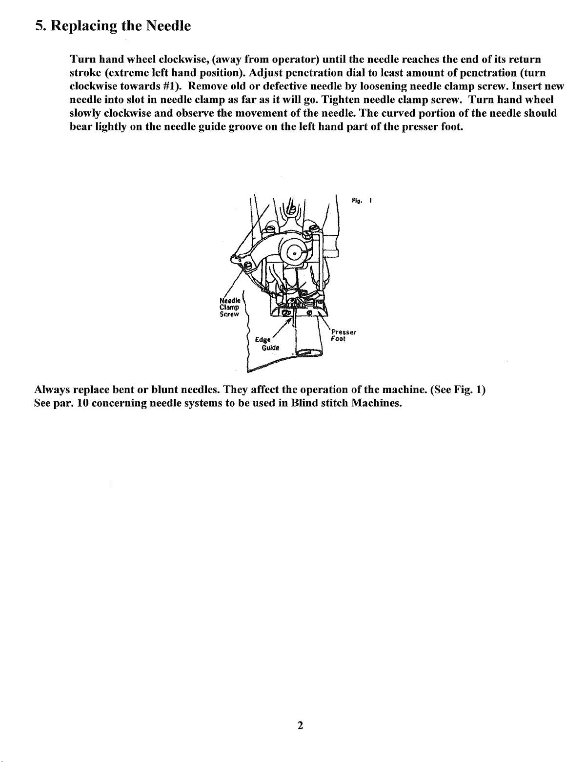
5.
Replacing the Needle
Turn
hand
wheel clockwise, (away
stroke
clockwise
needle into slot
slowly clockwise
bear
(extreme left
towards
lightly
on
in
and
the
from
hand
position).
#1). Remove old
needle clamp as
observe
needle guide groove
the
Adjust
or
far
movement
operator)
penetration
defective needle by loosening needle clamp screw.
as
it
will go. Tighten needle clamp screw.
of
on
the
the
left
until
needle.
hand
the
needle reaches
dial to least
The
curved
part
of
the
amount
portion
presser
the
end
of
penetration
Turn
of
the
foot.
of
its
needle should
return
Insert
hand
(turn
new
wheel
Always replace
See
par.
10 concerning needle systems to
bent
or
blunt
needles. They affect
be
used
the
operation
in
Blind stitch Machines.
of
the
machine. (See Fig. 1)
2
Page 5
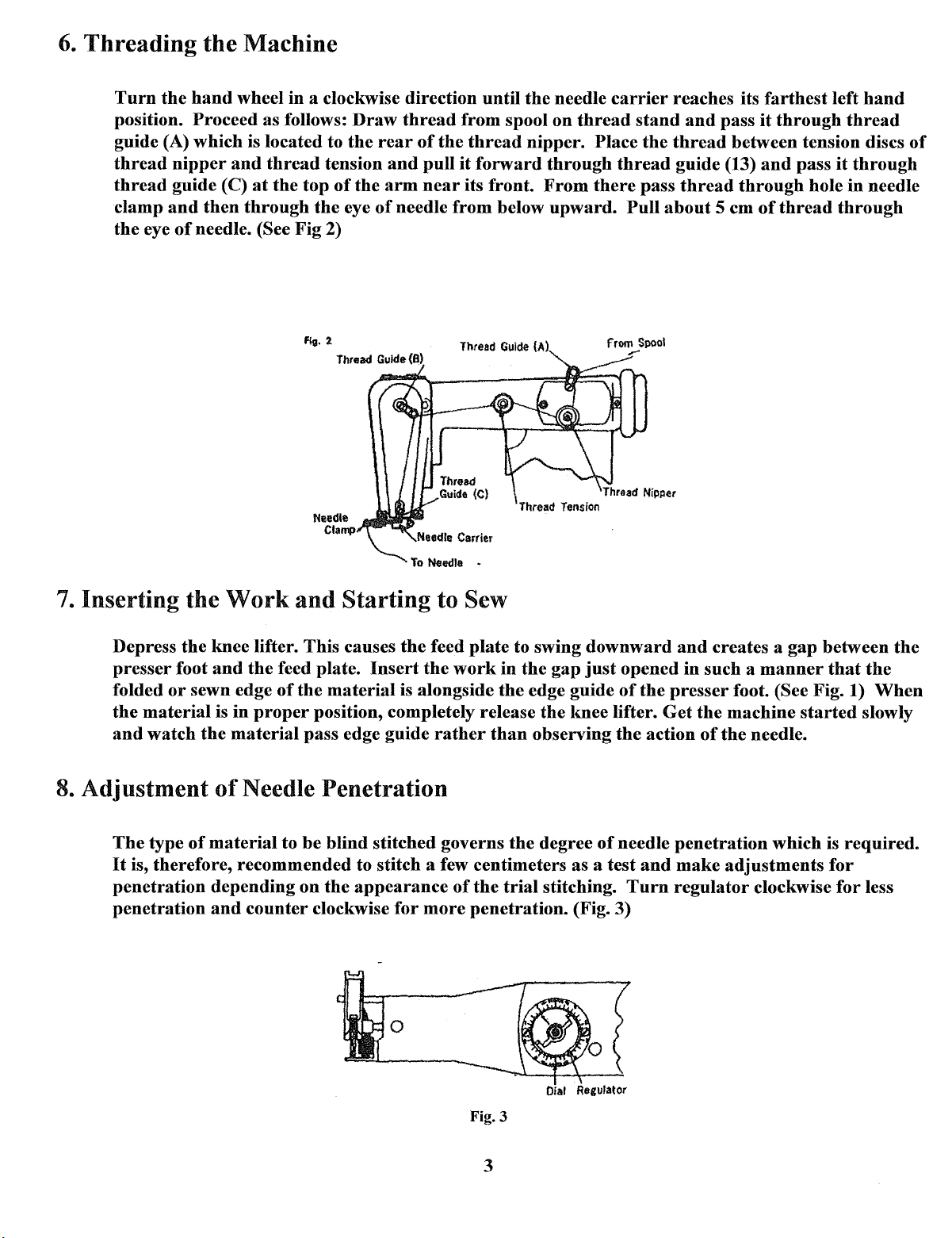
6.
Threading
Turn
position. Proceed as follows:
guide (A) which is located to
thread
thread
clamp
the
the
nipper
guide (C)
and
eye
of
the
Machine
hand
wheel in a clockwise direction until the needle
and
thread
at
the top
then
through
needle. (See
the
Fig
Draw
the
tension
of
eye
2)
the
rear
and
arm
of
needle
thread
of
the
pull
near
from spool on
thread
it
forward
its front.
from
below
Thread Guide (A)
carrier
thread
nipper. Place
through
From
upward.
thread
there
Pull
from
,...
reaches its
stand
the
thread
guide (13)
pass
about
Spool
and
pass
thread
5 em
farthest
it
through
between tension discs
and
through
of
thread
left
hand
thread
pass
it
through
hole in needle
through
of
7.
Inserting the
Depress
presser
folded
the
material
and
watch
8.
Adjustment
The
type
It
is, therefore, recommended to stitch a few centimeters as a test
penetration
penetration
Work
the
knee lifter. This causes
foot
and
or
sewn edge
is
in
the
material
of
Needle Penetration
of
material
depending on
and
counter
the
feed plate.
of
proper
to
and
the
Starting
Insert
material
position, completely release
pass edge guide
be
blind stitched governs
the
appearance
clockwise
to Sew
the
feed
the
work
is alongside
rather
of
for
more
0
plate
in
the
than
the
trial
penetration. (Fig. 3)
to swing
the
gap
edge guide
the
observing
the
degree
stitching.
downward
just
opened in such a
of
the
knee lifter.
the
action
of
needle
and
Turn
and
creates a
presser
Get
penetration
make
regulator
foot. (See Fig. 1)
the
machine
of
the
adjustments
gap
manner
started
needle.
which is
clockwise
between
that
the
When
slowly
required.
for
for
less
the
Oial
Fig.3
3
Regulator
Page 6
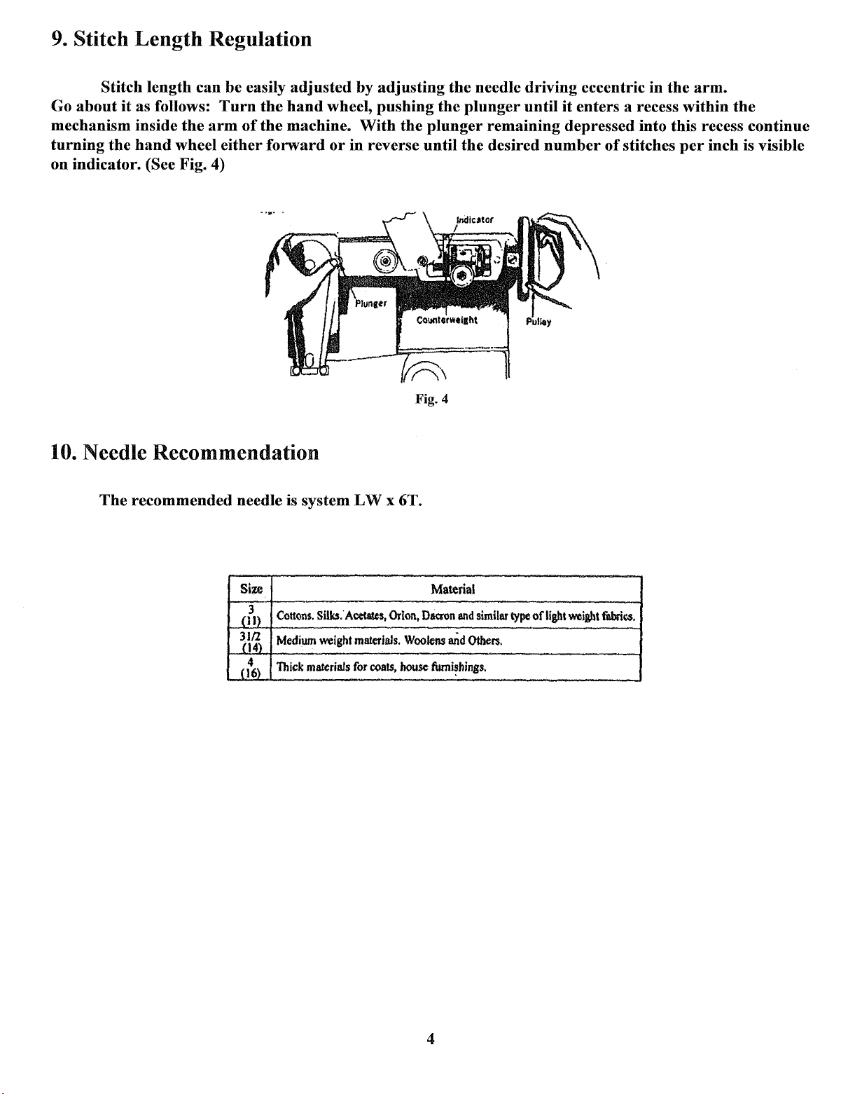
9.
Stitch Length Regulation
Stitch length
Go
about
it
as follows:
mechanism inside
turning
on indicator.
the
hand
(See Fig. 4)
can
be
easily
Turn
the
arm
of
wheel either
adjusted
the
hand
the
machine.
forward
10. Needle Recommendation
by
wheel,
With
or
in
adjusting
pushing
the
reverse
Fig. 4
the
the
plunger
plunger
until
the desired
needle driving eccentric in the
until
it
enters a recess within
arm.
the
remaining depressed into this recess continue
number
of
stitches
per
inch is visible
The
recommended needle is system
Size
3
Cottons.
_(11}
Medium
~\~
4
Thick
(16)
Silks.'
weight
materials
LW
Acetates,
materials.
for
coats,
x 6T.
Orion,
Woolens
house
Material
Da®n
end
similar
type
and
Others.
fumi~hings.
ofligbt
weigbt
fabrics.
4
Page 7
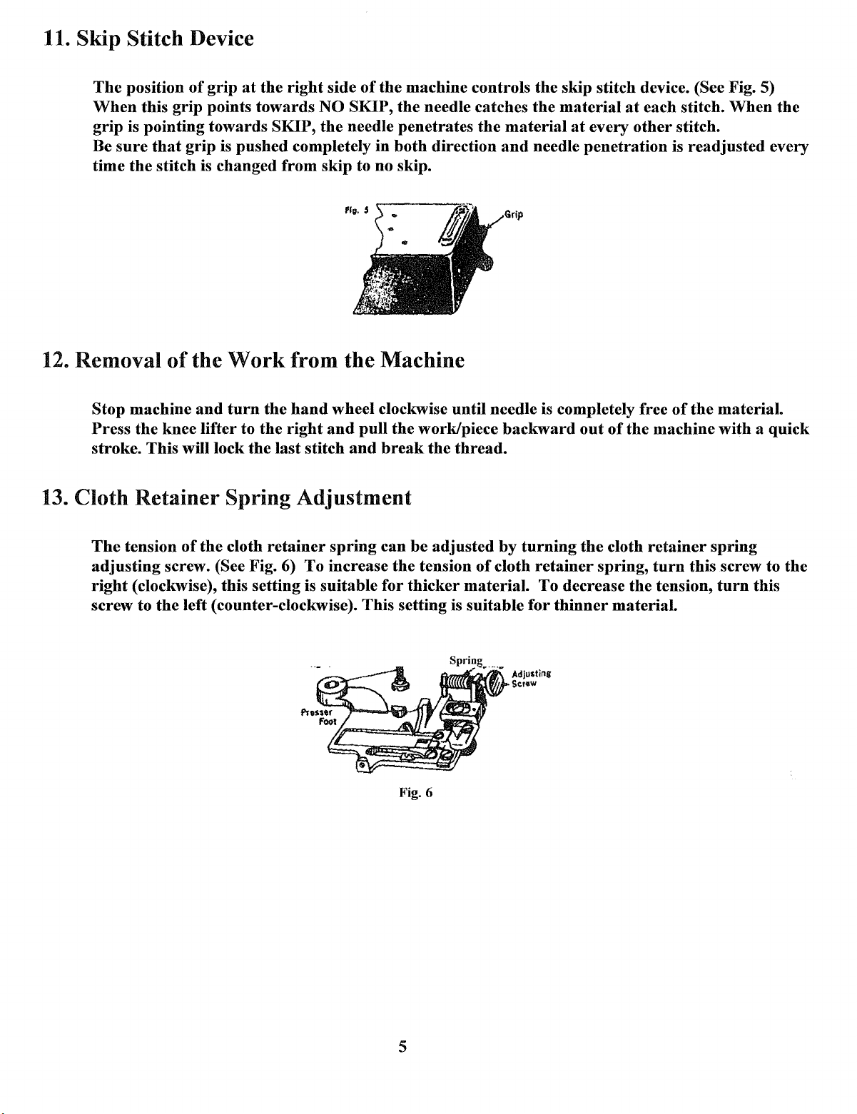
11. Skip Stitch Device
The
position
When
grip
is pointing
sure
Be
time
the
this grip points
of
grip
at
towards
that
grip
is
pushed
stitch is changed
the
right
towards
SKIP,
completely in
from
side
of
the
machine controls the skip stitch device. (See Fig. 5)
NO SKIP,
the
needle penetrates
skip to no skip.
the
both
needle catches
the
material
direction
and
the
material
needle
at
at
every
penetration
other
each stitch.
stitch.
is
readjusted
When
the
every
12. Removal
Stop
machine
Press
stroke. This will lock the last stitch
13. Cloth
The
adjusting
right
screw to
the knee lifter to
Retainer
tension
(clockwise), this setting is suitable
of
the
Work
and
turn
Spring
of
the
cloth
screw. (See Fig. 6)
the
left (counter-clockwise). This setting is suitable
from
the
hand
wheel clockwise until needle is completely free
the
right
and
Adjustment
retainer
spring
To
increase the tension
the
Machine
pull the work/piece
and
break
can
for
the
be
adjusted
thicker
Wi\IUII'!ir.IIY/J'
thread.
material.
backward
by
of
cloth
AdJU$tins
...
Sc:r•w
turning
retainer
To
decrease
for
thinner
out
of
the
cloth
spring,
the
machine
retainer
turn
the
tension,
material.
of
the
material.
with a quick
spring
this screw to
turn
the
this
Fig. 6
5
Page 8
14. Stitch Stabilizing Guide
The
Stitch Stabilizing Guide is
thin
material.
Stabilizing Guide
Be
sure
to tighten Stitch Stabilizing Guide Set Screw firmly on
after
the Stitch Stabilizing Guide
If
a tight stitch is
Set Screw
and
an
effective tool
required
on
for
thin
sewing soft
and
medium
and
materials, loosen
remove the Stitch Stabilizing Guide.
presser
has
been removed. (Refer to Fig. 7)
uniform stitches on extremely
the
Stitch
foot
at
the
same position
CAUTION: Please
take
Fig. 7
good
care
not
to lose Stitch Stabilizing Guide
after
removal.
6
Page 9

PARTS
LIST
CONTENTS
Machine Frame & Covers Components
Main
Shaft Mechanism Components
Needle
Looper
Ridge
Disc
Forming
Oscillating
Carrier & Feed
Drive
Mechanism & Presser
Disc &
Mechanism & Knee
Dog
Mechanism
Feed
Plate
.........................................................
Foot
Mechanism
Press
Components
Thread
Work
Standard Accessories
Tension &
Plate,
Knee
Nipper
Press & Belt
............................................................................
Parts
Components
Cover
Parts
......................................................
Components
Parts
Components
Components
Shaft
....................................
.....................•....
..............................
Parts
....................................
...............................................
Components
.........................•......
1
2, 3
3,
.4, 5
6
7
8
9
1 0
4
Additional
Additional Parts for Model
Parts
for
Model
CM
101 (Non-Skip Stitch)
CM
101
..........................
....•.............................
o
••••••••••••••••••••••••••••••
11
12
Page 10

Machine
Ref. No.
Frame & Cover
Pam
No.
4139
1
2 4144
4137
3
5227
4
4138-B
s
4141
6
1
4140-A
4143.
8
4048-A
9
10 AMIOO-Il
tl
11091 End
12
lllS3
4214
13
14
AC-15
AC-17
15
AC-16
16
Arm
Side
Arm
Side
Arm
Side
Arm
Side
Arm
Top
Arm
Top
Arm
Top
Belt Guard
Belt
Guard
Machine
Cover
End
Cover
Machine
Machine
Machine
Machine
Components
DeJcription
Cover
Cover
Set
Screw
Cover
Plate
Cover
Plate
Screw
Cover
Plate
Cover
Plate
Screw
Cover
Plate
Washer
Set
Screw
Frame
Set Sctew
Base
Felt
Pad
BaS8
Clamp
Screw
Base
Washer
Base
Nut
1
Page 11

Main Shaft Mechanism Components
18
R~f.l\lo.
1
llOOs
2
3
4217
4
4128--.1\
5
413J
6
132
7
8
4134
9
l(i
11
12
13
14
114
llOQ6
4003-.1\
6048
96
4162
Parr, No.
Oek,it:~tion
Main
13J
98
Shaft Bushing
Alain
Shaft
Felt
1Ju$hing
Oiling
Oil
Cap
Counterw!!\sht (WfStitch Length NuJnbers)
Couttterweight Set Screw (Shott)
~ounterweight
Stitch Length Indicator
Slitch Length Indicator Set Screw
Main Shaft Bushing (Rear}
Main
Shaft
Thread
Tension
~eteasing
Thread
Tension
Skip Stitch Gear <Small)
Releasing Eccentric Set Screw
Wrono
Set
Screw
Set Screw (Long)
£ccentric
2
Page 12

Main Shaft Mechanism Components (continued)
15
16
17
18 105 &;centric Rod Set Screw
19
20
21
22
23
24
25
26
27
28
29
JO
31
% Skip Stitch Gear Set Screw
525-A
4065 Eccentric Rod
114-B
4077-A
132
4163
4164 Eccentric Rod Connection
4166-A
131
4168
Eccentric Rod Assembly (w/Ref. Nos. 17, 18)
Eccentric Bushing Screw
98
Stud
Eccentric Rod
Skip Stitch Gear Shaft Collar (Small)
Skip Stitch Gear Shaft Collar Set Screw
Skip Stitch Gear (Large} Assembly
Skip Stitch Gear Shaft
Skip Stitch Gear Shaft Set Screw
Skip Stitch Gear Shaft Collar
Stud
Set
132 Skip Stitch Gear Shaft Collar Set Screw
4142-B
131
4207-A
Hand Wheel (Pulley)
Hand Wheel
Hand Wheel Rubber Cap
Set
Screw
Screw
(large)
3
Page 13

Needle
Carrier
& Feed Dog Mechanism Components
Ref. No.
1
2
3
4
s
6
7
8
9
10
11
12
13
14
15
16
17
18
19
10
11
22
23
24
2S
26
21
28
2.9
30
31
32
33
34
35
36
37
38
39
40
Parts No.
4128-A
4217
4623-A
Oil C.p
O.lling
Needle Carrier
Description
Felt
4024 Needle Carrier Set Screw
4019 Needle
Canier
Shaft
4022 Noedle Carrier Shaft Collar
129-8
4020-A
129-
4021-A
129-A
4017-A
4018-A
114-
Needle Caniei
Shaft
Needlo Carrier Shaft
A Needle Carrier
. Needle
Needle
NeedleCaulor
Canier
Carrier
Shaft
Shaft
Shaft
SbaftCrank
Needle Carrier Shaft Crank
A Needle Carrier
Shaft
Collar Set Screw
BUJhln.g
Bushing Set Screw
BuJhin&
BuJhin&
Set
Crank Clamp Screw "
11139 NeedlcCfamp
121
4181
1151 Needle Drivins Eccentric Assembly
4211
4173
4009-B
4012-A
4010
4011-A
4014
4()]5
1 1 902 Feed
11124-J
11121
10129 Feed
2528 Feed
4048-A
1152
4173
4642-A
4044 Feed Link
4043
129-
520-A
129--A
Needle
Clamp Set Screw
Ntedle{Sy,tem
Reaulator A Serews (Ref. Nos.
-C
Balt Connecting
Ball
Connecting
Needle Driving Eccentric
Stitch
Regulator Sc:rew
Stitch
Regulator
Stitch
Regulator Spring
BallConnectlJ1i
Ball Connecting
Rod
Rod
Lever
Oiling Felt
OiJCap
Do,g
Dog
Washer
Screw
&.
Stud
Link Clamp Sctew
-A
Feed
Feed Dos Set
Feed Link
FMd Link Stud Set Screw
Feed
A Feed
Stitch
Stitch
Ec011ntric
Link
Ecoontdc
Link
Ecoonuic Stud Bushing
Length Regulating Plunger Assembly
Length Regulating Plunger
LW
Rod
Rod
Ban
x 6T)
Set
Screw (Short)
Set Screw
Set
Cap
Cap
Set
Stud
Stud
Bushing
Screw
Screw
(Front)
(Rear)
Set Screw
Screw
wjRod,
19-
22)
(Lon,g)
Set
Screw
Set
Screw
4
Page 14

2
24
.-
15
Looper Drive Mechanism &
Looper Drive Crank Assembly w /Looper Y
A
Screws
Looper
Looper Drive Clank
Looper Drive Crank Stud Collar Set Screw
Looper
Looper Yoke Set
Looper Yoke
Looper Yoke
Looper Carrier Assembly
Looper Carrier
Looper Carrier
Looper Carrier
Looper Carrier
Looper Carrier
Looper
Looper
Eccentric
Eccentric
PteJSer
Presser
Presser
Presser
Presser
Presser
P.resscr
Plain
Needle
Stitdl Slllbili:dJis Guide
(Ref. Nos.
Drive
Yoke
Clamp Screw
Sleeve
Sleeve
Foot Set Screw
Foot Bracket
Foot
Foot
Foot
Foot
Foot
Presser
Guide
2-8)
Clank Set
Stud
Screw
Pin
Pin
Set Screw
Nut
BaU
Joint Set Screw
Ball
Joint Clamp
Ball
Spot Screw
A Pin
Clamp Screw
Bracket Adjusting Screw
Bracket Holding
Braclcet
Washer
HoldUtg
Screw
Auembly (Ref.
Foot
2
3
4
s
6
7
8
9
10
11
12
13
14
15
16
17
18
19
20
21
22
23
24
25
26
27
27-1
538-A
4191
5039-A
129-B
4030-A
4031
4032-A
8142
539-A
4035-A
4116
4216
4213
4179-D
4040
4039
sos
4038
4050
4061-A
4062
121-B
11158
4186-A
PFlOO
4049-B
11563
11563-A
Presser
Screw
Nut
w/BaU
Joint &
Screw
Screw
Nos.
26-40)
Foot
olce
Screws
(Ref.
Parts
Nos.
1 O-J S
Components
5
Page 15

Looper
28
29
30 4185 · O!alnfna Finger Set Screw
31
32 4185
33 4056
34 4054
35
36 4053
37
38
39
40 4059 Edge Guide
41 4185
Drive Mechanism &
4052-B
4058-A
4055CAS
4183
130-.B Ooth Retainer Eccentric Stud
4051-C
4182 Ooth Retainer Stopper Set Screw
Needle Guide Set Screw
O!aining Finger
Oath
Retainer
Oath
Retainer Screw
Ooth
Retainer Spring
Ootlt
Retainer Eccentric Stud
Ooth
Retainer
Ooth
Ret.uner Eccentric Stud
Ooth
Retainer Stopper
Edge
Guide Set Screw
~ccentric
Presser
Stud Set Screw
Bushing
Bushing
Foot
Set Screw
Parts
Components (continued)
Ridge
Forming
Disc & Feed Plate Mechanism Components
7
6 I
5~
6
Page 16

Ridge
Forming
Disc & Feed Plate Mechanism Components
Rof. No.
l
l
3
4
5
6
7
8
9
10
11
12
13
14
15
16
17
18
19
20
21
22
2l
24
25
26
1.1
28
29
30
31
32
n
34
35
36
37
38
39
40
41
42
Parts No. Description
11220-T
4208
52Z2-B
f:llSO
4109-A
4111 Rid,ie Formin& Dlsc Shaft Collar
129-B
4112
lll-B
SIS-A
108
4176
4102 Dille Adjusting Holder
4 HIS Disc
98
4107
98-A
4104
4105
4106
4103-A
5208
U075-A
4(143
98
4090
129
SHi-B
4101 Feed Plate Taper Bearing Screw
4070
4096 Feed Plate Shoulder Bearing Screw
4093-BA
4094 Feed Plate Sprifl!l Screw
Ridge
Forming Disc
Ridge
Forml11g
Ridge Formin& Disc Washer
Ridge Forming
Ridge
Forming Disc ,Shaft·
Ridge Forming Disc Shaft Collar
Ridge Formhlg Disc Shaft Crank
Ridge Forming Disc Shaft Crank Set Screw
BaU
Joint&. Stud Assembly with Screws (w/Ref.
Ball Joint Set Screw
B!!U
Stud Nut
AdjU$ting
Disc
Adjusting
Disc
Adjusting
Disc Adjusting Holder Pivot Bearing Pin Set Screw
Disc Adjusting Holder Spring
Disc Adju$tlng Holder Spring Screw
Disc Adjusting Holder Spring Nut
Disc Adjusting Holder Spring Stud
Disc
Adjusting Holder Spring Stud Nut
Fet~d
Plate Shaft
Feed Plate Shaft Bushing
Feed Plate Shaft Bushing Set Screw
Feed Plate Shaft Collar
-8
Feed Plate Shaft Collar Set Screw
Feed Plate Assembly w/Screws& Nuts (Ref. Nos. 29, 30)
Feed Plate
Feed Plate Spring
Disc Nut
Disc
Positioning Pin
Holder Pivot Bearing Screw
.Holder
.Pivot Bearing Screw Set Screw
.Holder
Pivot Bearing
Nut
~~
4095 Feed Plate Spring Adjusting Nut
4091-A
113-B
4122
4129 Disc Adjusting Dial Set Serew
519-AA
4010
4011 Disc Adjusting Regulator Spring
115 Disc Adjusting Regulator Base Set Scxew
Feed Pltlte Bracket
Feed Plate Bracket Set Screw
Disc Adjusting Dial
Due AdjuS!ing Regulator Assembly
Disc
Adjusting Regulator Ball ·
Screw
Pin
N;,.
10
7
Page 17

Disc Oscillating Mechanism & Knee Press Shaft
Parts
Components
8
Page 18

Disc Oscillating Mechanism & Knee Press Shaft
Rot.
No.
17
18
19
2()
21
22
23
24
z.s
26
'27
28
2~
3()
31
32
:n
34
JS
36
37
38
39
40
41
42
43
44
4.5
46
47
48
49·
so
.51
.sz
10
11
12
1:)
14
J5
16
1
2
J
..
.5
6
7
8
9
p,...n No.
4013-A
4074
407.5
416?
406.5
H4-B
s-.406688
119-B
4115
129-A
4065
4031-A
4069-A
4010
4076
4017-A
132
131
4098-A
lOS
4178--A
5;!()7
4()85
-406"1-A
4068-A
4083
4084
4087
4088-A
52(17
4085
4081-A
4206
420S
4177
H063-A
11!139
4221
4084
4222-A
4U6
11050
4061.1-A
4171
4010
40ll
4174
4170
4172
4173
4l1:S-A
4070-A
Dl•c
Ooclllatln.a;
Dbc:
Osclllatlna
Dltc
O.tcll!Atlng
Conn.,clina
Connactlna
Conn.,ctl.ng
Dbc
Oscilla(mg
Disc
OacUiatms
Dllc
Owclllatlnlf
DMc
O•clliAtmg
Dllc
OtclU..tln.a
Disc
Oocillatlna
Disc
O&c111atms
Disc
Osdllatlnt~
Disc
O•cillatlns
Disc
OsclllatlJ1jC
Disc
0scllla1lne
Dhc
O•cillatln,g
FeC!d
Plato
Fcod
Plate
Ctank
Ctank
Connecting
Connecll.t1g l..inl<
Conncctlna
Kne"
Pren
Knoe
l'l'eu
ConneC:tlJl,l!
Connec:ttns
Connecting
Crank&.
Knee
Prell.
Kne4>
Prou
KneCI Pc:en
Knee
Proto
K11oe
Prefl
Knee
f'r•••
KnC!a
Pro••
knee
Pr.;u
knee
l'r"u
Knee
Prou
Knoe
Prttn
Knee
Prest
Slclp-Stltch
Skip-Stitch
Skip-Stitch
Sldp-Stltch
Skip-Stitch
Skip-Stitch
Skip-Stitch
Skip-Stitch
Skip-Stitch
Oe6t:ript:ton
R<>d
Rod
Rod
Rod
Rod
Ro4
Ro<l
Rod
Rod
Rod
Rod
Rod
D"prouing
Doprcasins
&.
J..lnk Sh(!Uld<Cit
<'It
Ltnk
Shouldu
Link
Ll.t1k
Sh...Ct
Shaft
Unk
Link
l.Jnk
Unk
Shoulder
Shaft
Shaft
Shaft
Sh11ft
Sloove
Shaft
Shaft
Wa•her
Stop
Lev"r
Stop
Lever
Stop
LovC!r
Stop
Lovot
Stop
Love•
Stop
Lever
Selectl.t1g
Selecting
SeiC!ctlng Sprl.t1g
Selecting
Selvc:tlfl#
Selcctl.t1J;
Scloctlnc:
Selecting
Selecting
Rod
l:lrac;Jc;.,t
Rod
Bracket
Rod
Braclcel
Stud
Stu<l
Set
Rod
AuembiY
Rod
Shaft
Rod
Pin
Pin
Stud
Stud
Bracket
Bucl<et
ttracl<61
Bracket
)hack.,!
Bradc.,t
Ct.o.nk
Cranl<
Screw
ScH•w
{La•ge)
Guide
Scrow
Guld<~:
Screw
Crank
Crank
Sot,Screw
(Small}
Set
S<:rew
Set
Screw
Screw
Buthin.g
Bu•hing
Waoher
Bushing
Clamp
Spdng
Spdng
Limit
Limit
Cr!p
Ball
Spring
Ctlp
Cam
Cam
Cam
Stud
Cam
Stud
Spdns
Sprlfl#
Spflng
Scr<>w
Set
S..t
Screw
Set
Sc:rcw
Spdnt~
Sprlnj!
Shaft
Shaft
Sha(t
Shaft
S"l
Nut
Nut
Nut
Nut
ScJ<>w
Pl.t1
$or(Ow
Screw
Holder
Bushing
Sot
Screw
Nut
(wfRe(.
Setcw
Collar
Set
Screw
Nut
Screw
Nut
Stud
Stud
Collar
No.
Nut
Set
Sctcw
8}
Screw
Parts
Components
9
Page 19

Thread
Tension & Nipper
Parts
Components
23
ll
24~
10
Page 20

Thread
Tension &
Nipper
Parts
Components
Allf. No. Partsl\19.
11136
1
113-A
2
3
4 79-B
s 77
5190-A
6
7 4204 Tluead Tension
4209
8
4068-A
9
4201
10
4202
11
12
4203-A
13 4193
14
4199
15
4198
16
17
18 5067
19
20
21
22
23
24
25
26
71
5190-A
4197
11162
6053 Thread Nipper Releasing
130-B
4195-C
8158
4194-A
8158
'l'htead Guide with
Thread Guide Set
81
Tfuead Tension Nut
Thread Tension Sprina
TJuead Temion
Tluead
'Thread
'Thread
Th.rcad
Thread Tendon
'J.'hread
Thread Guide Set
Th.read
Thtead Nipper Spring
Thread Nipper
Thread Nipper Disc
Thr~d
Thread Nipper Disc Prop
Thread Nipper
Thread Nipper
Thread Nipper
Thread Nipper
Thtead Nipper
Th.read
Dm:rlpti~n
Ceramic
Screw
Washer
Te!Uion
DW.:
DisC
Pin
Tendon Staff
T,nlion Staff Nut
Tension Staff Bracket
Releasing
Guide
Pin
Screw
Nipper Nut
Washer
Nipper Staff
Nipper
Releasing
Relc<asing
Releasing
Releasing
Releasing
Releasing
Pin
Pin
Pin
Pin
Pin
Pin
Pin
CoUar
Collar Set Screw
Support
Support Set
Lever
Lever Set Screw
Screw
11
Page 21

Work
Plate, Knee Press & Belt Cover
Parts
Components
18
1
20
12
Page 22

Work
Plate, Knee Press & Belt Cover
Parts
Components
Ref. No.
Parta No.
4153
2
4156
3
5230
4
4157-A
5
4159
4160
6
7
4161
8
4048-A
4158
9
10 4154-A
11
12 4155
13 132
14
4180
15
4146-A
16 4147-B
17
4148-A
18
4212
19 4149
20
4147-B
'"21
*22
4219-A
11554
"23 5233
"24
11551 Belt Cover
Work
Wotk Plate Latch
Work
Plate Latch Set Screw
Wodc
Plate Bracket
Work
Plate Bracket Spring
Work
Plate Bracket Leaf
Work Plate Bracket Leaf
Work
Plate Bracket
Work
Plate llracket Set
Work
Plate Shaft
Work
99-A
Plate Shaft Sctewed
Work
Plate
Work
Plate Shaft Collar Set
Work
Plate Shaft Set Screw
Knee
Press Rod
Knee
l'reu
KneePreuRod
Kneel'reuPad
Knee
Press Plate
Knee
Press Plate Set Screw
Belt Cover
Belt
Cover
Belt
Cover
Oo$ctlption
Plate
Shaft
Collar
Sleeve
Rod
Sleeve
Bracket
Bracket Set Screw
Wood
Screw
Leaf
Set
Pin
Sprlng
Sprlng
Sprlng
Screw
Cap
Screw
Screw
(Long)
(Short)
Set Screw
•
*Extra
Accessories
13
Page 23

Standard
Accessories
1
14
Page 24

Additional
Parts
for Model CM101 (Non-Skip Stitch)
~·
3
17 18
?I
16
~
15
,~~
13~
~
8
@
~
~
11
12
/
15
Page 25

Additional
Ref,
No.
Parts No.
1 4145
2
4110-AA
3
4 105
5
6
7
B
9
10
11
12
13
14
15
16
17
18
.S07-A
98
4218
4065
S4066AB'
129-8
4031-A
4115
129-A
4069-A
4070
4078
4070
4067-A
4068-B
Parts
Disc OsciUating
Disc Oscillating
Disc Oscillating
Disc Oscillating
Connecting
Connecting Link Guide Screw
for
Model CM101 (Non-Skip Stitch)
Description
Screwed
Ecoentric
Eccentric Rod Set Screw
Eccentric Bushing Screw
Oiling Felt
Disc Oscillating
Disc Oscillating
Disc Oscillating Rod Shaft Set Screw
Disc Oscillating Rod
Due
DiscOseiUating Rod Pin Set Screw
Ridg~
Forming Disc
Oscillating
Cap
(for
hole
of
Rod
Assembly (w/Ref. Nos.
Rod
Stud
R9d
Assembly (w/Ref. No.
Stud
Rod
Pin
Rod
Brack~t
Rod
Bracket Spring Stud
R~d
Bracket Adjtuting Screw
Rod
Bracket Adjusting Screw Nut
Unk
Guide Screw
Grip
Set Screw
4171)
Spring
Nut
4-6)
9)
Stud
Nut
16
Page 26

Additional
Parts
Ref. No.
1
2
3 11563
4
s
6
1
8
9
10
11
12
13
14
·IS
16
17
18
19
Parts No. OM<:ription
PFlOOH
4301-C
4052-B
4304
4182-A
4302-S
4308
10037
10038
121
4312-A
10040
10039
5233-A
4311-A
15128
4058-A
418S Otaining Finger Set Screw
Universal Presser Foot ASJembly (Ref. Nos.
l'tain Univetsal Presser
Needle Guide.
Needle Guide Set Screw
Edge
Guide
Edge Guide Set Screw
Ootb
Retainer
.
Ootb
Retainer Set Screw
Ootb
Retainer Holder
Ootb
Retainer Bracket
Ooth
Retainer Bracket Set Screw
Ootb
Retainer Spring
Ooth
Retainer Spring Adjusting Screw
Ootb
Retainer Spring Adjusting Screw Prop
Ooth
Retainer Spring Adjusting Screw Prop Set Screw
Ootb
Retainer Spring Bushing
Ootb
Retainer Spring Pin
Chaining Finger
2-19)
Foot
17
 Loading...