

Page 1
®
an
INSTRUCTION
TACKERS
&
BUTTON
BOOK
er
&
PARIS
SEWERS
BOOK
CLASSES:
552, 554, 555, 558,
600, 660, 710
cJ..ancller
CHAN
•
oyer,
543, 546, 548,
DL
ERM~HINE
mass.Ol432 u.
s.a
,
tel.
(617)
560,
~
CO
772-3393
Page 2
FLAT
HOOK
BUTTON
AND
SEWERS
EYE ............................. Model 710-1HE ..........................
............... Model 710-1 ...............................
Model 710-5 ...............................
Model 710-10 ............................. 24 stitch, side vih
Model 710-35 .............................
710-55 .............................
Model
710-85 .............................
Model
710-120 ........................... 24
Model
Modei710-5HE
..........................
16
stitch. side vih
12
stitch. side vih.,
16
stitch. hack & forth.
16
stitch, cross (X) stitch.
12
stitch, back & forth,
sti~ch,
l6
stitch. side vib
l2
stitch, side vib.,
square
..
..
pattern.
.•
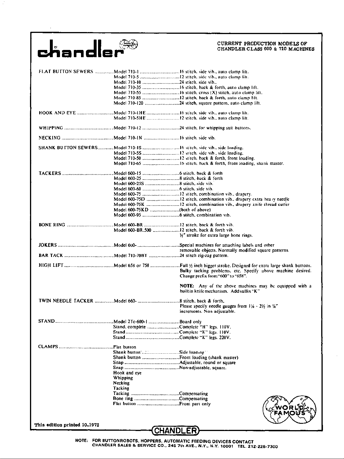
CURRENT PRODUCTION MODELS OF
CHANDLER CLASS 600 & 710 MACHINES
auto
clamp lilt.
auto
clamp
lilt.
auto
ch1mp hft.
auto
clump lift.
auto
clamp lift.
auto
clump lift.
auto
clamp
clamp
lil1.
lift.
auto
WHIPPING
NECKING ......................................... Model 710-IN ............................
SHANK
TACKERS
BONE
JOKERS
BAR
HIG~
TWIN
....................................... Model 710-12 ............................. 24 stitch. for whipping suit buttons.
BU
ffON
SEWERS
......................................... Model 600-15 ............................. 6 stitch. back & forth
RING
.....................................
............................................
TACK
....................................... Model 710-70BT ........................ 24 stitch zig-zag pattern.
LIFT
.......................................
NEEDLE f ACKER
............ Model 710-IS .............................
............... Model 660- ................................. 8 stitch. back & forth,
71
Model
Model710-50
Model 710-65 .............................
Model
Model
Model 600-60 ............................. 6 stitch, side vih.
Model 600-75 .............................
Model
Model
Model 600-75KD .......................
Model
Model600-BR
Model
Model
Model
0-5S .............................
.............................
600-25 ............................. 8 stitch, back & forth
600-25S ........................... 8 stitch, side
600-750
600-75K ..........................
600-95 ............................. 6 stitch,
600-BR.500 .....................
600- ................................. Special machines for
658
..........................
............................
or
758 ....................... Full ~ inch bigger
16
stitch. side vib.
16
stitch. side vib
12
stitch. side
12
stitch. hack & forth, front loading.
16
stitch.
12
stitch,
12
stitch.
12
stitch.
(both
of
combination
12
stitch, back & forth vib.
12
stitch, back & forth vih.
Yt
stroke
removable objects. Normally modified square patterns.
Bulky tacking problems. etc. Specify
Change prefix from
NOTE: Any
built
in
knife mechanism. Add suffix
Please specify needle gauges from
increments. Non adjustable.
..
side loading.
vi b ..
side loading.
h<~ck
& forth, front loading. shank master.
vih_-
combination
combination
combination
above)
for
extra
vib.,
dmpery.
vib ..
dmpery
vib., drapery knife thread
Vlb.
large bone rings.
attaching
stroke.
Designed
"600"
to
"651<".
of
the
above
machines may be
labels
I~ -2~
extra
and
for
"K"
hea
other
extra
above
'Y
needle
cutter
large
shank
machine desired.
equipped
in
~,.
buttons.
with a
STAND
CLAMPS
This
.............................................. Model 2Tc-600-l ........................ Board only
...........................................
edltion
printed
10.1972
Stand,
complete .........................
Stand
..........................................
Stand
..........................................
Flat
button
Shank
button-
..
:-.;;
Shank
button
Snap
........................................... Adjustable,
Snap
........................................... Non-adjustable, square.
Hook
and
Whipping
Necking
Tacking
Tacking ......................................
Bone ring ...................................
Flat
button
....................... Side loaaang ·
.............................
eye
.................................
Complete
Complete
Complete
Front
Compensating
Compensating
Front
"H"
"K"
"K"
loading
part
(shank
round
only
~----~------------~CHANDLER~--------------------
NOTE:
FOR
BUTTONROBOTS, HOPPERS,
CHANDLER
SALES & SERVICE CO.,
AUTOMATIC
246
7th
AVE
FEEDING DEVICES CONTACT
.•
N.Y., N.Y.
legs. I
IOV.
legs. IIOV.
legs. 220V.
master)
or
square
10001
TEL.
212-226-7300
Page 3
:..
.....
MECHANICS
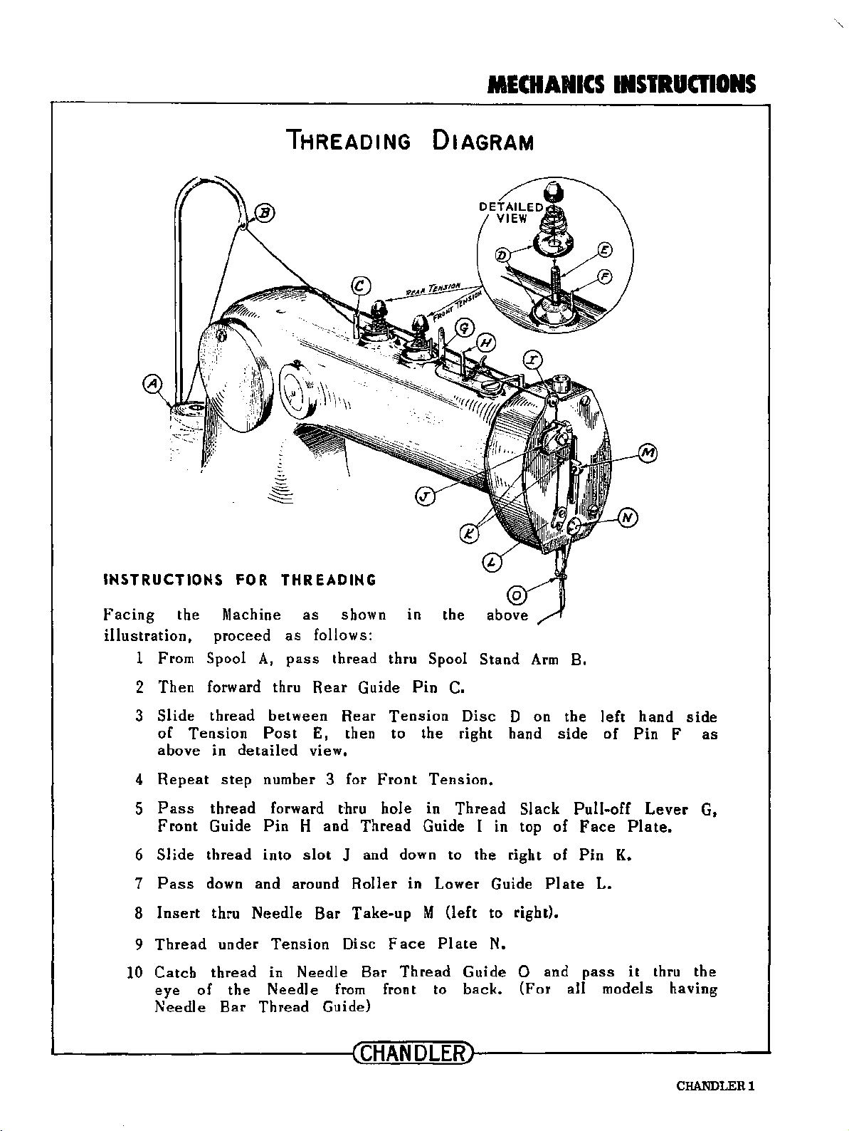
THREADING DIAGRAM
INSTRUCTIONS
INSTRUCTIONS
Facing
illustration,
10
the
1 From Spool
2
3
4
5
6
7
8
Thread
9
Catch
eye
Needle
Then
Slide
of
above
Repeat
Pass
Front
Slide
Pass
Insert
forward thru
thread
Tension
thread
Guide
thread
down and around
of
FOR
Machine
proceed
A,
in
detailed
step
thru
Needle
under
thread
the
Bar
Thread
THREADING
as
shown in
as
follows:
pass
between
Post
number 3 for
forward
Pin
into
Tension
in
Needle
thread
Rear
E,
view.
t·hru
H
and
slot
Bar
Needle
from
Guide)
Rear
then to
J and down to
Roller
Take-up
Disc
thru Spool
Guide
Tension
Front
hole
Thread
Face
Bar
Thread
front to
the
Stand
Pin
·C.
Disc
the
right hand
Tension.
in
Thread
Guide I
in Lower Guide
M
(left
Plate
Guide
back.
D on
in
the
right
to right).
N.
0 and
Slack
top
(For
Arm
B.
the
side
Pull-of£
of
of
Plate
all models
left
of
Face
Pin
L.
pass
Pin
Plate.
K.
it
hand
Lever
thru
side
F
as
G,
the
having
~--------------~CHANDLER~--------------~
CHANDLERl
Page 4
-CHANICS
IISTRUOIOIIS
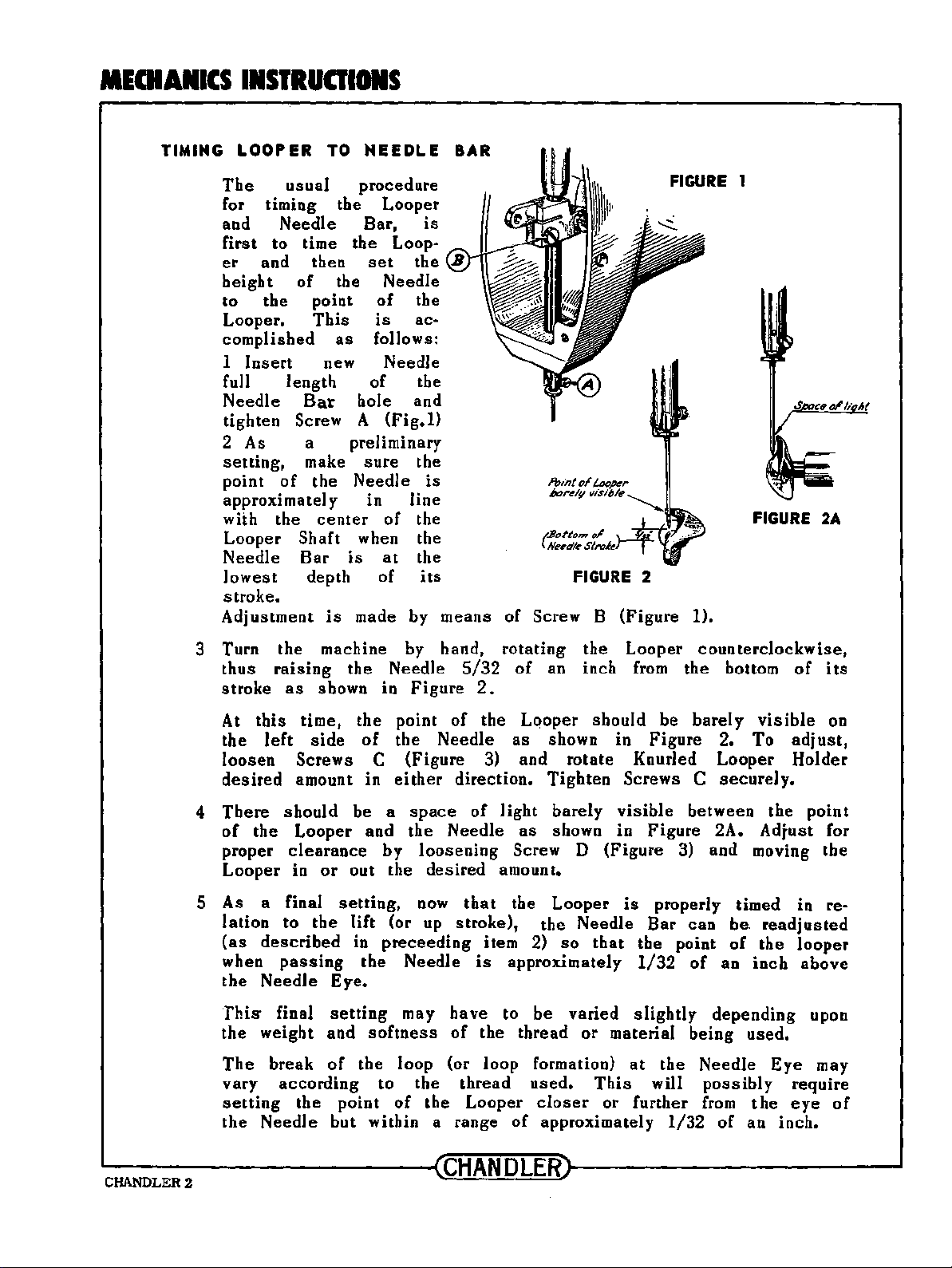
TIMING
LOOPER
The
usual
TO
NEEDLE
procedure
for timing the Looper
and
first
er
height
to
Looper.
Needle
to time the Loop-
and then
of
the point
This
complished
Insert
1
fuJl length
Needle
Bar hole and
tighten Screw A
Bar,
set
is
the
the Needle
of
the
is
ac-
as
follows:
new Needle
of
the
(Fig.1)
2 As a preliminary
setting,
point
approximately in
with the
of
make
the
center
sure
Needle
of
the
is
line
the
Looper Shaft when the
Needle
1 owes t depth of
Bar
is
at
the
its
stroke.
Adjustment
is
made by means
BAR
t.Boftom
( Neeel/e
of
Screw B (Figure 1).
ol
Sirek
FIGURE
2
FIGURE
1
FIGURE
2A
3 Turn
thus
stroke
At
the
loosen
desired
4
There
of
proper
Looper
the
raising
as
this
time,
left
side
Screws C (Figure 3) and
amount in
should
the
Looper
clearance
in
5 As a final
lation
(as
when
the
to
described
passing
Needle
This- final
the
weight and
The
break
vary
setting
the
according
the
Needle but within a range
machine by hand,
the Needle
shown in
the
be a
or
out the
setting,
the
lift
in
the
Figure
point
of
the
either
space
and the
by
loosening
now
(or up
preceeding
Needle
of
Needle
direction.
Needle
desired
stroke),
Eye.
setting
of
point
may
softness
the
loop (or loop formation)
to
of
have
of
the
the
rotating
5/32
of
2.
the
as
of
light
as
Screw D
amount.
that
the Looper
item 2)
is
approximately
to
the thread
thread
Looper
of
the
an inch
Lqoper
should
shown in
rotate
Tighten
barely
shown in
(Figure
the Needle
so
that
be
varied
or
used.
closer
This
or
approximately
Looper
from
Figure
Knurled
Screws C
visible
Figure
counterclockwise,
the bottom
be
barely
2.
Looper
securely.
between the
2A.
3) and moving
is
properly timed in re-
Bar
can
be.
the point
1/32
slightly
material
at
the
will
further
1/32
of
of
an
depending upon
being
Needle
possibly
from
of
of
visible
To
adjust,
Holder
point
Adjust
readjusted
the
looper
inch
above
used.
Eye
require
the
eye
an inch.
its
on
for
the
may
of
----------------~CHANDLER~----------------
CHANDLER2
Page 5
MECHANICS
IISTRUOIOIIS
\
~
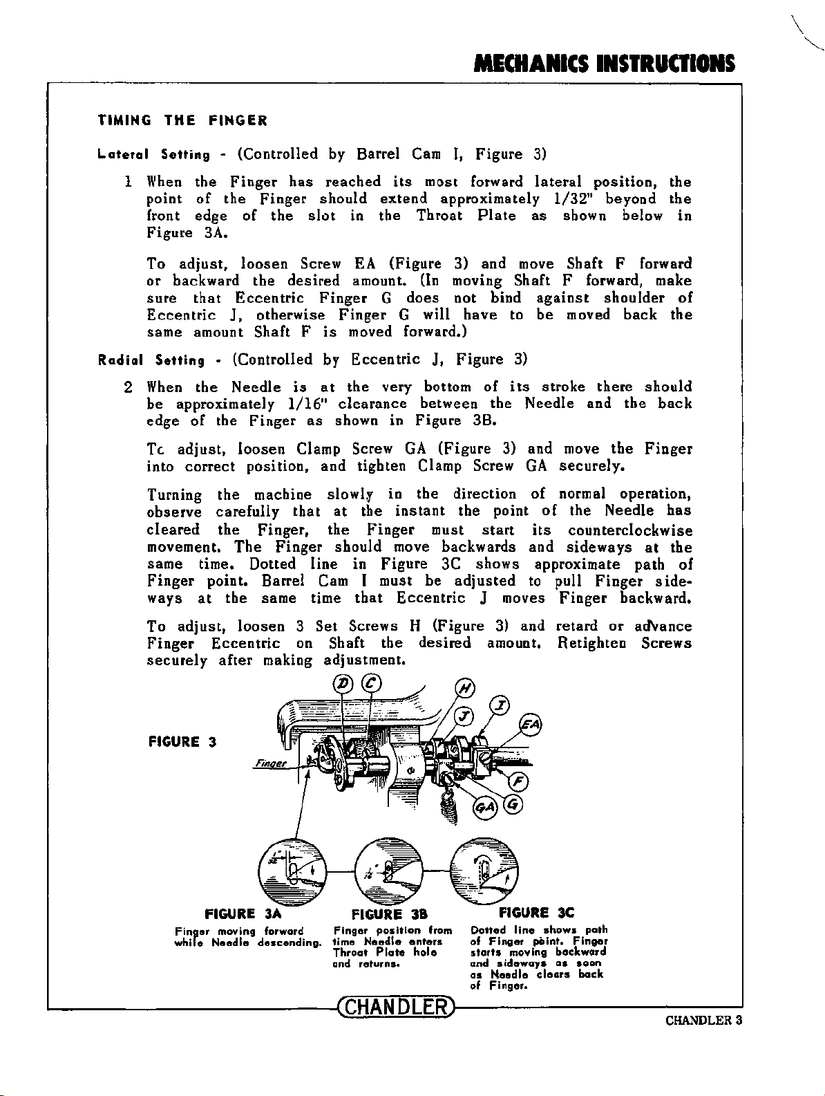
TIMING
Lateral
1
Radial
2
THE
Setting
When
point
front edge
Figure
To
or
sure
Eccentric
FINGER
- (Controlled by Barrel
the
Finger
of
the
3A.
adjust,
backward
that
J,
has
Finger
of
the
loosen
the
desired
Eccentric
otherwise
Screw
same amount Shaft F
Setting
When
be
edge
Tc.
into
Turning
observe
cleared
movement.
same
Finger
ways
- (Controlled by
the
Needle
approximately
of
the
Finger
adjust,
correct
loosen
position,
the
carefully
the
The
is
1/16"
Clamp Screw
machine
that
Finger,
Finger
time. Dotted
point. Barrel Cam I must be
at
the same time
reached
should
slot
in
extend
the
EA
amount.
Finger
G
Finger
is
moved forward.)
Eccentric
at
the very bottom
clearance
as
shown in
and
tighten Clamp Screw
slowlf
at
the
the
Finger
should
line
in
Figure
that
Cam
its
I,
Figure
most forward
3)
approximately
Throat
(Figure
{In
does
G will
J,
between the
Figure
GA
Plate
as
3) and move Shaft F forward
moving Shaft F forward, make
not bind
have
Figure
of
to
3)
its
Needle
3B.
(Figure
3) and move
GA
in
the
instant
must
direction
the point
start
of
its
move backwards and
3C
shows
adjusted
Eccentric
J moves
to pull
lateral
1/32"
position,
beyond
shown below in
against
be
stroke
moved
there
and
shoulder
back
the
the
securely.
normal operation,
of
the Needle
counterclockwise
sideways
approximate
path
Finger
Finger
backward.
the
the
of
the
should
back
Finger
has
at
the
of
side-
To
adjust,
Finger
securely
FIGURE
Finger
while
~--------------~CHANDLER~--------------~
loosen
Eccentric
after
3
FIGURE
moving forward
Needle
making
3A
descending.
3
Set
Screws H (Figure 3) and
on Shaft the
adjustment.
FIGURE
Finger
time
Throat
and
position
Needle
Plate
returns.
desired
38
from
enters
hole
amount.
Dotted
of
Finger
starts
and
sideways
as
Needle
of
Finger.
II
ne
point.
moving
clears
retard
Retighten
shows
path
Finger
backward
as
soon
back
or
ad'vance
Screws
CHANDLERS
Page 6
MECHANICS
INSTRUCTIONS
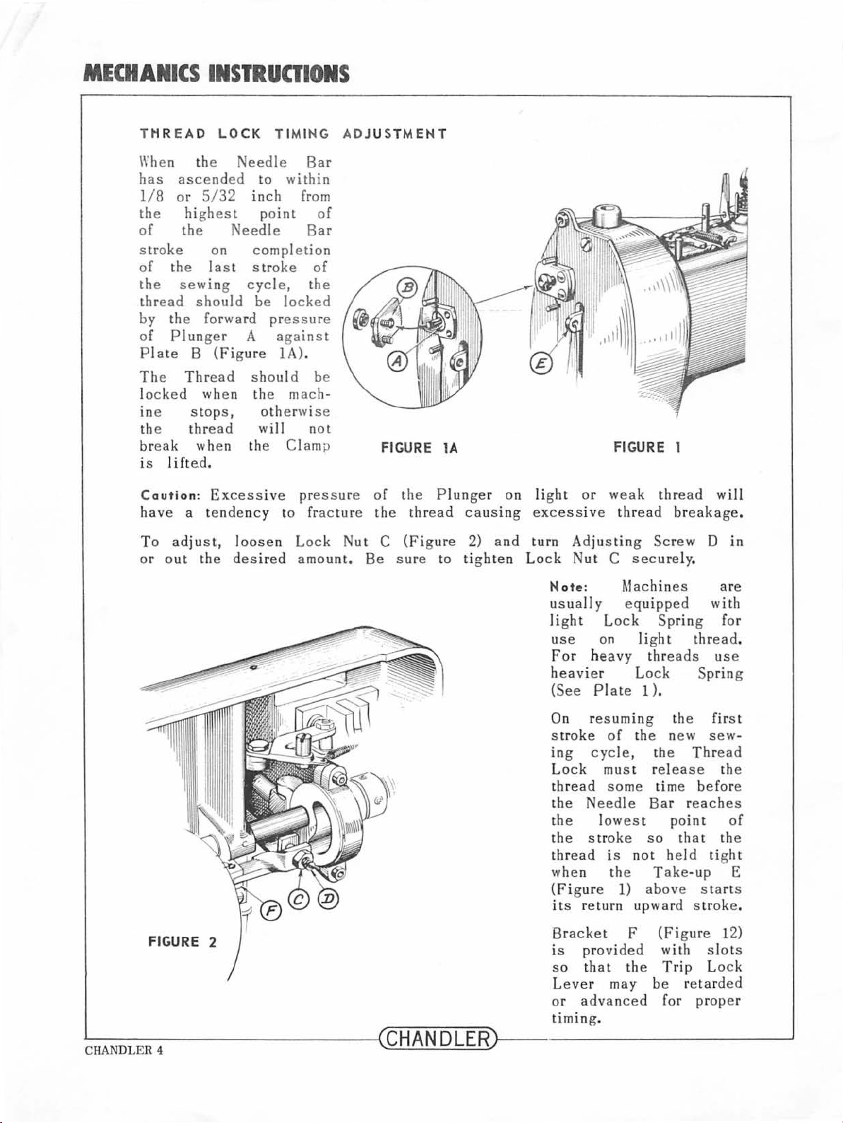
THREAD LO
\\'he n the
has
ascended
1/8
or 5/
the
of
hi
the
ghest
stroke
of
th e
the
sewi
thr
ead
shou
32
on
last
ng
CK
TIMING
Needle
to
inch
po
Needle
completion
stroke
cycle,
ld
be locked
Bar
within
from
int
Bar
of
the
by the forwa rd pressure
of
Plunger
PI
ate B
The
l
in e
the
ocked
Thr
wh
stops,
thread
break when
is 1 ift
Caut
have
To a
or
ion
out
a t
dju
ed.
:
st,
the
A
against
(Figu
re
1A).
ead
shoul d
e n the mach-
otherwise
will
the
Clamp
Excessive
endency
loose
to
n Lock
desired
be
not
pressure
fra c
amount.
ADJUST
of
ture the
Nu
MENT
FIGURE l A
of the P l
thr
ead
t C (Figu
Be sure
re
to
unge
causi
2)
tigh
r on li
ng
excessive thread breakage.
and
turn Ad j
ten L
ght
ock
FIGURE 1
or weak
usting
Nut
C
thre
Screw
secure
ad
ly.
will
D in
FIGURE 2
~------
CHANDLER
4
----
N ote: Machi
usually
li
ght
use
Lo
on ligh t
For heavy thr
heavier
(See
On r
stroke
ing
L
ock
thr
the
Plate
esuming
of
cycle,
must release
ead
some
Ne
edle
the lowest
the
s t
roke
t
hread
when
(Figur
i
ts return upward
Br
1s
is
the
e 1)
acket
provided
so that
Leve
r may
or
advance
ming
ti
.
nes
e
quipped
ck
Spring
with
thread
Lo
eads
ck
us
Spring
1 ).
the
first
the new
th e
time
Bar
sew
Thre
befo
reache
point
so
that
not held tigh t
Take
-up E
above starts
s t
roke
F (Fig
the
with
Tr
ip
ure
slots
Lock
be retarded
d fo r proper
--------~CHANDLERr----------------
are
for
.
e
-
ad
the
re
s
of
the
12)
--
.
--~
Page 7
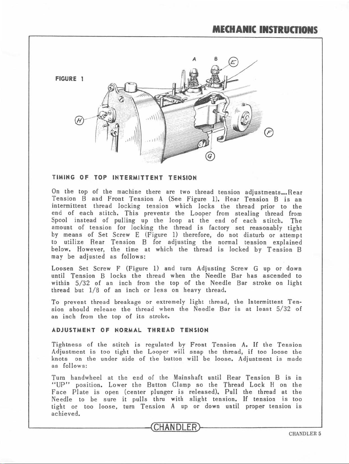
FIGURE 1
MECHANIC
INSTRUCTIONS
0
TIMING
On the
Te
nsion
intermittent
e
nd
Spool instead
amo
by means
to
b
elow.
may
Loosen
until
within
thread
To
sion
an inch from th e
ADJUSTMENT
Tightness
Ad ju s tme
knots
as
top
of
each
unt
of
utili
ze
However,
be
adjusted
Set Screw
Tension
5/32
but
prevent
s ho
nt
on the
follows
OF
TOP
of
the
B
and
thr
ead lockin g t
stitch.
of
tension
of
Set
Rear
B
of
l/ 8
thread
uld release
OF
of
the stit
is too tig
under
:
INTERMITTENT
machin
Front
Tension
th e time a t
as
locks
an
of
Tens
This pr
pulling
for l
ock
Screw
F
a n
breakage
top
NORMAL
E
follows :
(Fi
gu re
the
inch
inch
th e
thr
of
its
ch i s regul ated
ht
th e
side
TENSION
e th
ere
are two
ion
A (See Figure 1).
ens
ion
which locks
eve
nt s the
up
the l
oop
ing
the
thr
(Figure
B for
l)
thr
ead
from the top
or l
or extr
ead
stroke
THREAD
Looper
of
the butt
adjusting
which
and
ess
eme
when
.
l)
wh
on
will
on
thread tens
Loop
at
the
ead
is
therefore,
the
thread
turn
Adjusting
en
th e
of
the
heavy
ly light
the
Needle
TENSION
by
Front
s n
ap
will
ion adjustments •••
Rear
the
er from s tealing
end of
factory
do
the normal tension
is
Needle
Needle
thread.
thread,
Bar
Ten
sio
th e thread,
be loose.
Tension
thr
ead
prior
each
set
reasonably
not
dist
urb or
locked
Screw
Bar
Bar stroke on lig
the
is
n A.
by
G
has
Intermittent
at leas
If
if too loose
Adjus tm
B
is
to
thr
ead
stitc
h.
atte
expl
ained
Tension
up
or
down
ascended
t 5/
32
the
Tension
ent
is
made
Rear
an
the
from
The
tight
mpt
B
to
ht
Ten-
of
the
Turn
"UP"
Face
Need
tight
achieved
~------
handwheel
position.
Plate
le to be
or
to o l
.
is
at
Lower
open
sure
oose,
----------
the
end
of
the
th e
Button
(center
it pulls thru
turn
plunger
Tension
Clamp
with
A up
--~CHANDLER~
Mainshaft
so
is
rele
slight
or
until
the
ased
down
--
Rear Tension
Thread
).
Pull
tension.
until
the
If
prop
Lock
thread
ten
H on
s ion is
er
tension
B
at
is
in
the
the
too
is
----------------~
CHANDLER 5
Page 8
MECHANICS
FIGURE 1
INSTRUOIONS
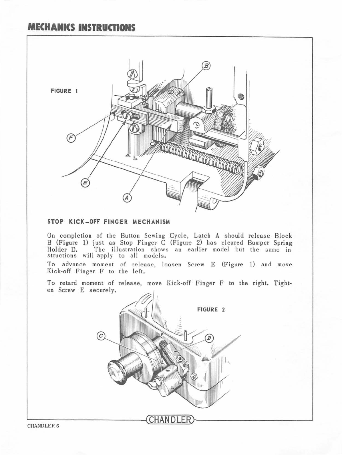
STOP
On
completion
B
(Figure
Holder
st
ruction
To
advance
Kick-off
To
retard
en
Screw E
KICK-OFF
of
1)
just
D. The
s will
Finger
apply
moment
moment
securely.
FINGER
the
as
illu
F
to
of
MECHANISM
Button
Stop
stration
to all models .
of
the left,
release,
Finger
rel
ease,
Sewing
C
shows
loosen
move
Cycle,
(Figure
an
earlier
Screw
Kick-off
Latch
2)
has
model
E
Finger
FIGURE 2
A
shou
cleared
(Figure
F· to
ld
but
the
release
Bumper
the
same
1)
and
right.
Block
Spring
in
move
Tight-
~----------------~CHANDLER~----------------
CHANDLER 6
~
Page 9
MECHANICS
INSTRUCTIONS
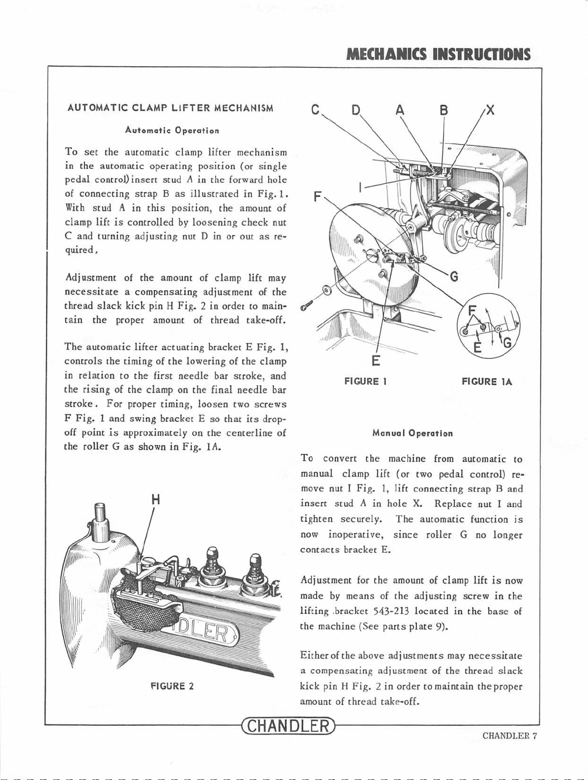
AUTOMATIC
To set
in the automatic
pedal
contro
connecting
of
With stud A
clamp
C a
quired,
Adjustment of
n
thread slack
tain
The
controls
in
the
s
F
off
the
lift
nd
turning adj
ecessi
troke.
tate a compensating
the
automat
rel
ation
rising
Fig.
1 and
point
roller G as
CLAMP
Automatic
the
automatic
l)
insert
strap B as
in
is
controlled
kick
proper amount of thread
ic
lifter
the timing of
to th
of
the
For
proper tim ing, loosen two screw
swing
is approxim
LIFTER
Operation
clamp
operating position
stud A in the forward hole
this
pos
by l
ustin
g nut D
the
amount
pin H
Fig. 2 in
actuatin
the lowering of
e first
clamp on
shown
needle
bracket E so that its drop-
ately
in
Fig.
MECHANISM
lift
illustrat
ition
, the amount
oose
ning ch
in
of clamp
adjustment
g br
acke
bar
the
final need
on the
1A
.
er
ed
or out
ordet
scroke, and
centerli
mechanism
(or sin
t E
the
gle
in
Fig.
eck
nut
as
lift
may
of
the
to main-
take-off.
Fig.
clamp
le
bar
ne
1.
of
re-
1,
s
of
FIGURE 1 FIGURE
Manual
To
convert the machin e from
manual cla
mov
e nut 1
insert stud A in
tighten
now inoperative, stnce
contacts
mp
Fig.
sec
urely.
bracket
lift
Operation
(or two
1,
lift
hol e
The automatic
E.
automatic
pedal contro
connecting strap B
X.
RepLace nut I and
function
roller
G no
longer
lA
to
l) re-
and
is
FIGURE 2
~--------------~C
Adjustment
made by
liftin
g .bracket 543-213 located
the machine (See
Ei
ther
a compen
kick
pin H Fig.
amo
unt of thr
HANDLER~----------
for the amount of clamp
me
of
the
sating adjustment of
ans of
above
ead
the adju
parts
plate 9).
adjustments
2 in order to maintain
take
-off.
lift
sting s
crew
in
the b
may ne
the
thread slack
the
cess
------~
is now
in
the
ase
of
itat
e
proper
CHANDLER 7
Page 10
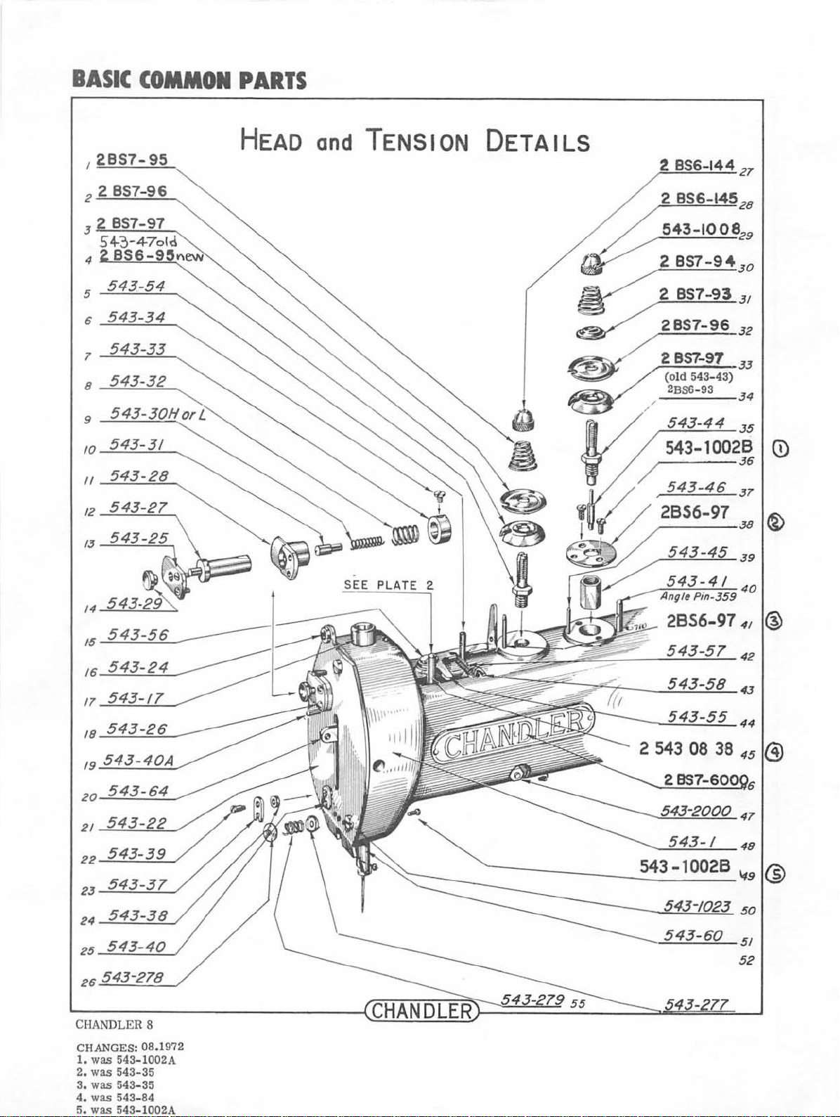
BASIC
COMMON
PARTS
I
2857-95
1
543-33
8
543-32
10
543-31
11
543-28
12
543-27
HEAD
and
TENSION
DETAILS
~32
2
856-144
2
857-93
2
857-97
(old
543-
2BS6-
93
21
31
33
43)
34
/8
19
20
21
22
23
24
25
26
543-37
54
543-
S
.
EE
PLATE
2.
CHANDLER 8
CHANGES: 08.1972
1.
was
543-1002A
2.
was
543-35
3.
was
543-35
4.
was
5.
543-84
was
543-1002A
Page 11
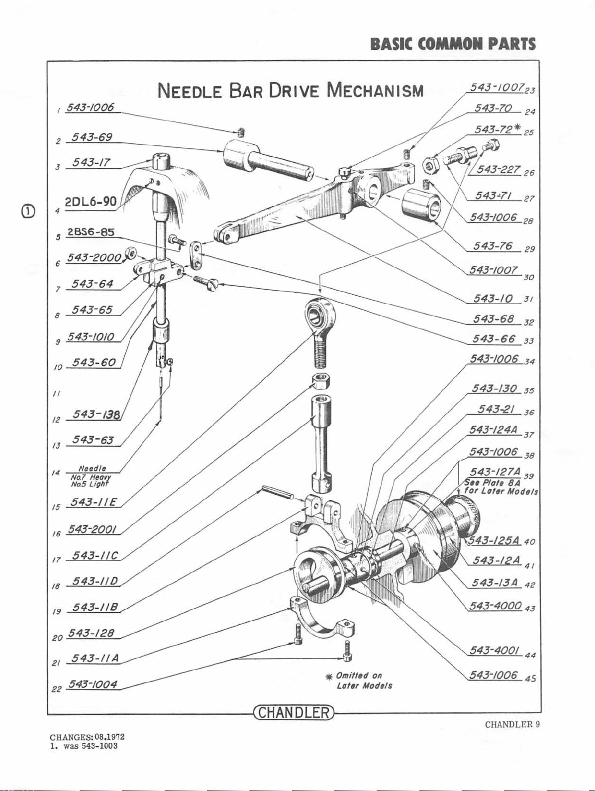
BASIC
COMMON
PARTS
I
543-/006
2
543-69
7
543-64
8
543-65
9 543-1010
NEEDLE BAR
DRIVE
MECHANISM
543-10
543-68
543-66
3 /
32
33
34
II
12
13
14
No.7
No.5
15
543-200/
16
17
18
/9
20
21
22
Nudls
Hsa1
Ligh
*
Omitted
Later
35
36
37
38
on
Models
~----------------~CHANDLERr-----------------~
CHANGES: 08.1972
1.
was 543-1003
CHANDLER 9
Page 12
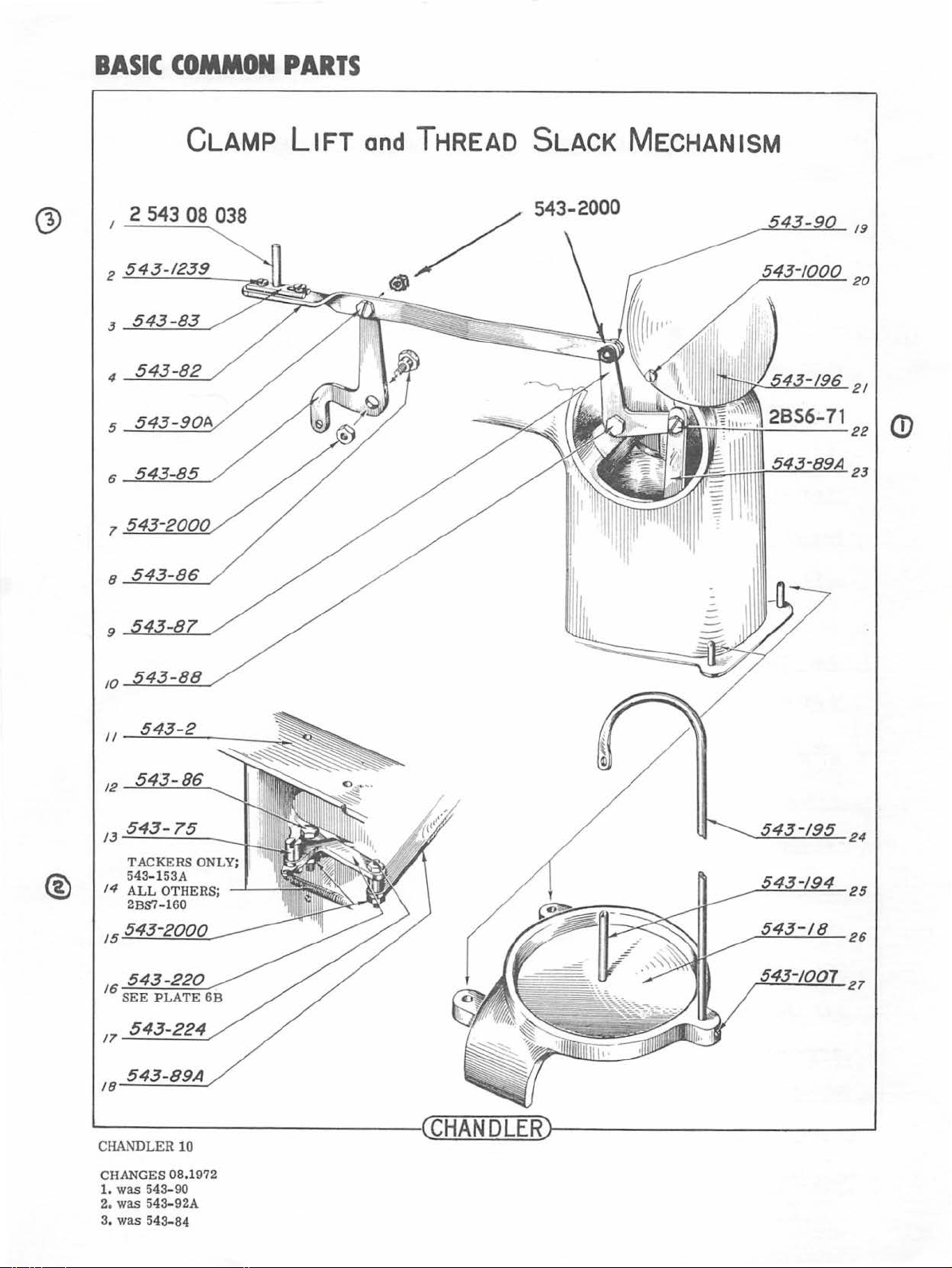
BASIC
COMMON
PARTS
CLAMP
2 543 08 038
8
LIFT
and
THREAD SLACK MECHANISM
' I
®
9
10
II
12
15
.....:::5;__;4...:::..3.......:-8::....::9...:...:A._,
18-
24
25
26
27
CHANDLER
CHANGES
1.
was
2. was 543
3.
was
10
08.1972
543-90
-92A
543-84
Page 13
BASIC
COMMON
PARTS
2
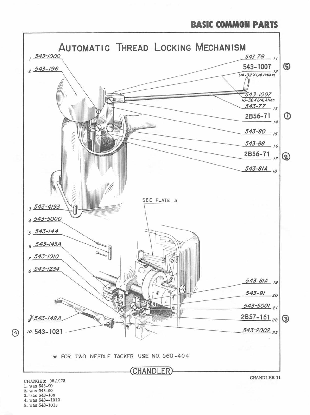
543-/96
AUTOMATIC
THREAD LOCKING MECHANISM
SEE
PLATE 3
2856-71
13
14
15
16
/1
/8
0
@
5
543-144
6
1
8
l.
/0
@
543-1021
CHANGES:
1.
was
543-90
2.
was
5
was
43-90
54
543--
543 -101
3.
4. was
5. was
08.1
3-169
1012
*
~
FOR
972
TWO NEEDLE TACK
ER USE
NO. 560
CHANDLER
-40
4
2857-161
CHAN
DLER
/9
20
21
22
23
®
11
Page 14

B
ASIC
CO
MMON
PARTS
2
543-1002
6
543-137
7
543-2
8
LOOPER
and
FINGER MECHANISM
552-320
543-/32
2857-
161
20
21
24
25
26
<D
®
®
G>
10
II
543-!24A
17
2856-400
18 543-141
CHAND
LE R
12
CHANGES:
1.
was
In
2.
was
3. was 543-1016
08.
543-121 & 122
1968
needle plate was
543- 205
4
1972
changed
543-4273
to
one pi
ece
--C-HA_N
__
D~L-=E=--R
4. was 543-1018
was
543-15
5.
was
543- 135
6.
7.
was
543-1003
29
20L6-90
552-315
552-320
1
JT
38
J9
(J)
Page 15

BASIC
COMMON
PARTS
CD
®
1
552-336
7
552-325
8
543-187
9
543-209
543-10028
II
543-330
/J--!:::....:..:::_-.=2 ____
FoR
CLAss 552
----.,
AND
LATER MoDELS
543-326
552-328
552-337
543-1002825
543-
22
2J
24
28
JO
J/
Q)
No
~----------
CHANGES: 08.1972
1.
was
552-329
2.
was
543-1002A
3.
was
543-184
Shouldu
--
----~~C~H~AN~D~L~E~R~
(N~w
Sho
ulder
Sly!~)
Stud
543-140;-:A
543-140
--------
-~---
~~
§.j_~'Qg?._~,B
--------~
CHANDLER
13
Page 16

CD
BASIC
COMMON
PARTS
STOPPING MECHANISM
NOTE: BELOW SPRING
IN 1948.
MODIFICATIONS.
SEE
FOLLOWING PAGES
STOP
DISCONTINUED
FOR
LATER
<D
@
12
------..
552-313
13 543-1010
543-/9A
16
2BS7-161
17
-------,.
NEEDLE TACKER
*
USE
NO.
560-402
T
USE
N0.560-403
L------------------4CHANDLER~--
CHANDLER
CHANGES: 08.1972
1.
was
2.
was 543- 20
3.
was
4.
was
14
543-169
543-1018
543-235
(a!ter
1970,
"C"
clips
used)
------
--------~
Page 17

BASIC
COMMON
PARTS
STOPPING
2 543 08 036
MECHANISM
INTRODUCED 1952
543-391
4
52-4000
5
552-1006
7~~-~4~0~0~0--------~~
-
FoR
CLASS
552
MACH.
552-33514
552-3002'15
552-309
16
8~~~0~0~6
*_5::....;5::....:;2:..._-.=....3:....::1
II
12
552-1010
FOR
TWO NEEDLE
*
USE
t
USE
·
------~~------~
8"-/
TACKER
NO.
560-429
NO.
560-
403
-
~------------------~CHANDLERr-----------------~
CHA
NGES : 08.1972
1. was 543-311,
also
see
assy
dwgs
CHANDLER 15
Page 18

BASIC
CO-ON
PARTS
STOPPING
MECHANISM
INTRODUCED 1971
~~---------552-3002
~~---------600-309
FOR
~-----------600-335
CLASS
600
MACHINE
600-332A
WASHER
FOR
CUSHIONSPRING
MUST
discontinued.
CLASS
WILL
WHICH
PURCHASED
SEE PAGE 34
COMPLETE
~----------------~CHANDLER~--------------~~
CHANDLER16
CHANGES: 08ol972
1. was 552-311. also see assy dwgs
THOSE
BE
552
BE
REPLACED
IS
FOR
UNIT.
WISHING
TO
HOLDERS,
PURCHASED.
)
REBOUND
BY
HEAVIER.
(600-
ASSEMBLY NUMBER
NEW
335).
CONVERT
PART
(spring
FINGER
A
NEW
SCREWS
FOR
NO.
no.
552
STOP
THEIR
600-323
-332
GUIDE
ONE
(
600
MUST
CLASS
ADAPTER
will
be
(552-309)
-
309)
ALSO
552
,
BE
Page 19

BASIC
COMMON
PARTS
<D
543-94
2
543-213
3
543-2002
4
543
5
543-10/9
6
7
-10
/9
TREADLES
and
TRIP
LEVERS
2855-177
543-2002
543
-1018
543-2002
543-1021
543
-200
/6
17
18
19
20
21
2 2
g)
®
8
9
II
/2
13
14
15
543-226
1010
24
25
26
27
28
29
30
~--
CHANGES: 08.1972
1.
2.
3.
4.
--
was 543
was
was B
was 543- 1019
54
3-7
S-7
-9
3
9
7
------
----
--~~
CHruA~N~D~L&E~Rr---
--
----
------
CHANDLER
--~
17
Page 20

OPTIONAL -NOT
FOUND
ON
ALL
MACHINES
GROOVE
4
555-380
PIN
AUTOMATIC
CLAMP
LIFTER
555-387
.
555-381
543-2000
13
14
15
®
5
6
7
555-377
8
543-3001
543-1023
9
II
555-382
~
--
CHANDLER 18
--------------~CHANDLER~------------------~
543-220A
543-2005
552-367
555-378
555-379
543-200018
555-383
543-241
/6
17
19
2 0
CHANGES: 08.1972
was 543
1.
was 543
2.
-101
-101
6
8
Page 21

n
I
0
...
rrl
543-1002
541-59K
552-320
KNIFE
MEOtANISM
OPTIONAL-see machines model
cover. Non-knife machines cannot
to
knife
machines,
"K"
different
SUFFIX
base casting.
MACHINES.
Hst
inside
be
conve··ted
front
543-10028
IOOWire
fil
hd
/4
1oowire
....
•
,..
•
;;;
....
....
(")
~
E3
~
t::l
::d
.....
CD
541-281
~EA-U8
HJ-Zil
-
-
PI:
-
-
PI:
•
...
-
Ill
I
,..
•
-
Ill
•
....
Page 22

TWO
NEEDLE
TACKER
TWO
2BS6-1442REQD
2 8S7 -95 2
2BS6-51
560-4201.
543-57 2 REQD
560-420R
560-445
560-421
543-34
543-33
543-32
543-31
543•
543-28
543-27
543-25
543-26
543-29
543-40 2 REQD
543-38
543-37
543-39
560-
543-1007
NEEDLE
REQD
30Horl
2 EA
414A-G
see
box
TACKER
2BS6-145
543-1008 I EA
2
BS7-9S 2 REQD
2 857-96 4
2
f1!R-97
et;0-441 2
~60-
I0-32X3/810C flathd
510-446 2 REQO
543-35
560-4 4Z5 2 REQO
560-407
560-415
543-17
543-24
543-1023
543-
560-408
543-1002A2
560-419
6-40x
560543-63 2 REQD
134-35-110 2 REQD
2 R£00
2REQD
REQ
4
REQD
REQD
442 2 REQD
4R£QO
2fEQD
2
REQD
40A 4
REQD
REQD
5/1611hd21'eqd
413A-H
see
bca
D
~----------------~CHANDLER~----------------~
CHANDLER20
Page 23

TWO
NEEDLE
TACKER
543-154A
NUT OTHER SIDE
TWO
NEEDLE
TACKER
2BS6-160
~
2856-4005
-
'part
no.
for MACHINE
_,..
looper
bro block
bot
r»Y«
loooer oft.
man
sft
nose
frame
moin
veer
loooer
aoor
needle pl
brg
block
bot.
OOYtr
looper
sfl
main
aft
nose
tom<
mcin gear
ooar
''0-4011
SI0-4008
St0·4MA
...,_...,.
K0·4ZIA
oto-401A
510-•UIII
510-4311
:IC0·40tE
$60-60$[
H0-433C
010-4108
010·421
D80-401C
!t60-438( 510-431
OI0-4"Y
*"'
I
1/4
I
1/2
__
...,..,
seo-•
oec
000-4>31
M0-4t0.
I<G-<ZU
~o.o--·
11
0·4liC
510-43a
MACHINE
SIZE
2"
2
1/4
~...,.,
$eO-~'
S80-433
C
80-4a01
510-4UI
8
SI0-401C
E
5S0-4M'
chort
for
c::orrect
SI~E
;;;-
I
3/4
M0-
4De
500-4000
SI0-4UI
,.,.4f0
* ·
4l:ll
Ia«>-
oto-4MD
c
Oto-
4Je
cent.
2 172
SI0-40tG
S&0-40~
O«l·
433C
810-W
t0-42ft
"0·40tC
,
M0-4310
..........
port
no.
no.
reQII
_
I
I
I
•
•
I
I
I
D
•
I
I
I
I
•
I
I
I
•
CHANGES: 08,1972
1.
was
543-92A
2.
was 543-169
3.
was 543-151
was 543- 1016
4.
CHAN
DLER
21
Page 24
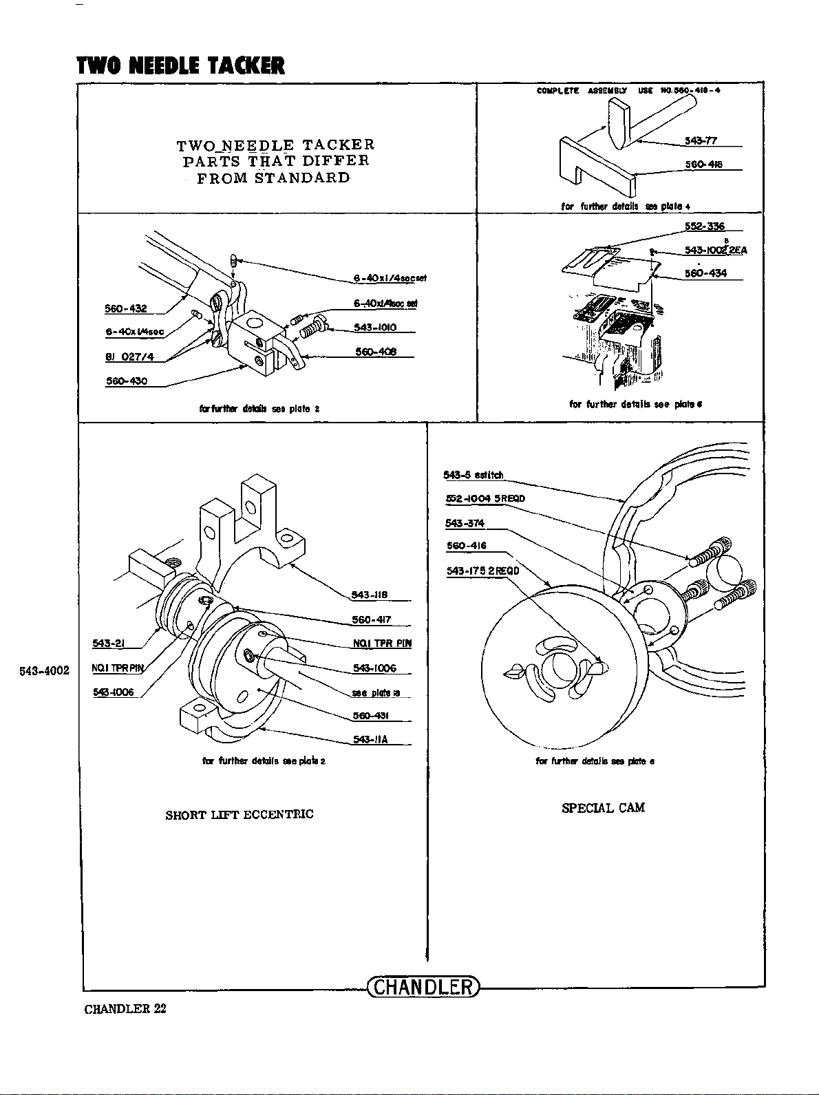
TWO
NEEDLE
TACKER
TWO
PARTS
FROM
fcrfwtlw dellils
NEEDLE
THAT
STANDARD
see
TACKER
DIFFER
plato 2
6-40xl/4socset
560-408
543-5 eatitch
560-416
for
further details
for further details
1110
plato 4
see
560-434
plate •
543-4002
543-118
560-417
NO.I
TPR
PIN
560-431
543-IIA
SHORT
for further details
LIFT
ae
plata
ECCENTRIC
2
for
further
derails
SPECIAL
see
CAM
plata •
~------------------~CHANDLER~------------------~
CHANDLER22
Page 25

TWO
543-301
543-299
560-422
543-299A
NEEDLE
TWO
TACKER
NEEDLE
TACKER
CLAMPS
-543-1002
S43-300A
543-1237 6
543-3003
REQD
6REQD
(!)
543-2003
543-300
543-!00t 2 REQD
2REQD
560-372
543-118
543-119
543-265X
*552-376
543-96
543-95
543-97
2REQD
552-375*
560-435 2 REQD
543-302X
543-1002
560-423
I Dart
MACH.
SIZE
too
aeo-..ooa
11/4
S80-400C
II/I
aeo-40ao
I
Sf4
11110-400!
2'
SS0-400f
21/4
1100-4000
1112
no.
for clamli
2
REQO
I bottom
ooo-40111
1100·401C
1100·401D
1100·401!
IIIS0-401F
oeo-401 G
~----------------~CHANDLER~----------------~
CHANGES: 08.72
1.
was
543-372
CHANDLER23
Page 26

CLAMPS
I
543-85
2
543-123
Q)
3 2856-158
BUTTON CLAMP ASSEMBLY
543-120
543-2004
543-119
18
19
20
543-/05
543-3000
543
543-114
Pin
543-1/0
552-369
543-97
-118
21
22
26
28
29
30
13
543-108
®
17
543-390
543-1015
~----------------~~C~HA~N~D~L~E~R~~--------------~
CHANDLER
CHANGES:
1.
was
2.
was
3.
was
4. was 543
24
08.
543- 116
543-1015
543-98
-11
5
1972
& 543-
99
Page 27

BUTTON CLAMP ASSEMBLY
All
In
One
Style
r 8
'
-32
CLAMPS
X 1
/4
SlOtted
hdless
See
Item
Plole
29
543-272
5
4
- 543-390
NOTE
Ports
Not
Bear
ing
Mimbers
Are
Identified
~-------------------------------------------~CHANDLER~-------------------~
On
Plate 5
CHANDLER 25
Page 28

CLAMPS
543-244
543-244A
2
543-243
3
543-246
4
543-260
5
54
7
8
9
543-237
10
3-238
SHANK
C/ol/1
BUTTON
Support
For
ATTACHMENT
54
3-2
45
543-250
543-249
543-105
543 -
257
543-3000
543-242
/9
20
21
22
24
26
27
28
29
18
543-2
55-C
WHEN
ORDERING,
BUTTON
BE
PROPER CUP
AND
SPECIFIED
LINE
SIZE
OF
SHANK BUTTON MUST
IN
ORDER
SIZE
AND
TO
SUPPLY
HEIGHT.
STAY
543-247 30
5
43-
2003
31
543
-241
543-240
33
~------------------~CHANDLER~--
CHANDLER 26
--
--------------
~
Page 29

CLAMPS
543-1000
SHANK
BUTTON
All
In
One
ATTACHMENT
Style
8-32x1/4 slotted hdls
4
543-390
Cloth
Supporl
Fo,
NOT£
Parts
Not Bearing Numbers
Are
Identified
WHEN
ORDERING,
8UTTON AND
BE SPECIFIED
PROPER
On
Plate
LINE
SHANK
IN
CUP
10
ORDER
SIZE AND HEIGHT.
SIZE
OF
TO
STAY
SUPPLY
BUTTON MUST
543-275
543-276
5
8
9
~----------------~CHANDLER~----------------~
CHANDLER27
Page 30

CLAMPS
I
543-299
2
43-299A
.3
543-2003
4
543-300
5
543-372
6
543•//9
7 543-118
8
543-303
543-303A
ATTACHMENTS
(CONT.)
543-30113
543-123714
543-300/.
543-300A
543-1002
543-302X
54!-1237
54!-3001
54~304
-265-4
15
Q)
9
543-5000
12
543-305A
Slay Bullon Plate
07
543-261A
double
Whippilll Allochment
bend
543-261 25
543-120
"
543-119
---...;....;;;;....~-28
543-262
543-263
543-1015
543-264
543
543-305
543-305C
26
27
29
30
31
32
.JS
CHANDLER28
CHANGES: 08.1972
1.
was
543-302
Page 31

CLAMPS
CD
543-271
I
2
3
4
543-267
5
43-118
ATTACHMENTS
Snap Aflachm6nf
For
Squar•
Snaps
(Cont.)
543-/237
543-300/
II
12
7
543-268
Under Side
NOTE•
Sam~
Snap Attachment
For
Round Snops
ASSEMBLY NUMBER
UNIT
All
OthtJr
Ports
As
Plot~
5
AS
SHOWN:
-4
COMPLETE
2-543-08-033
------------------~CHANDLER~------------------~
CHANGES: 08.1972
1.
was 543-1236
CHANDLER
29
Page 32

CLAMPS
543-2000
543-1002
543-299A
552-348
543-1237
552-342R
552-365
552-342L
552-364
552-344~
552-350
552-353
543-1014
~
552-343
552-346
___
552-347
CD
543-2003
A
''\.
_
oo
/
~
~
SHANK-
-&,
<
l
l
I
I
,,.
•
.
.
__:=:::r:e
:;:::
1
==:a
________;
___,
o
MASTER ATTACHMENT
l
~
I
I
_.
•
•
~
•,
• " •
/
J
.
'
~
1
....--
9 I--
I
0 0
543
543-1002
543-1237
543-300
543·3001
543·/20A
552-340
543·/18
5
543-272
I
•
8- 32-1/ 4
11
.
543-301
•
543-300A
543-299
-271
43-265
slotted
hd
less
@ 543-1017 .
552-366
543-1002
543-1002
552-345
543·1002~
~--------
CHANDLER30
CHANGES:
1.
was 552- 353
2.
was
3.
was
•
08,
552-352
552-351
/
l..-~
~
----------~
1972
1
CHANDLER~--
----
------------~
ASSEMBLY NUMBER
ABOVE
2-543-
ec_p
00
!
ENTIRE
08-
034
543-1002
543-266
543-302
552-341
-:43-3001
~
43·1237
FOR
UNIT:
Page 33

ACCESSORIES
Left
Hand Button
BUTTON
Spacer
ACCESSORIES
Left
Hand and
Button Spacer
~------------------~CHANDLER~------------------~
Right
Hand!
I NUT 543-2000
552-322
CHANDLER
3
31
Page 34

ASSEMBLY
GROUPS
NEEDLE
2 -543-08-001 standard machines
2-558-08-001 high
2-560-08-001 two needle tacker
BAR ROCKER
arm
ARM
ASSEMBLY
machines
FACE
PLATE
2-543-08-003 standard machines
2-560-08-003 two needle tackers
ECCENTRIC CONNECTING
2-543-08-002 standard maeblnes
2-558-08-002 high
2-560-08-002 two needle tacker
ASSEMBLY
arm
ROD
machines
.ASSEMBLY
THREAD
2-543-08-004 standard machines
2-543-08-004 two needle tackers
560
CLAMP
2-560-08-004-twa
CLAMP
2-543-08-006 standard machlnes
2-555-08-006 Automatic clamp
2-558-08-006 high
PUSH ROD ASSEMBLY
VERTICAL CONNECTING STRAP ASSEMBLY
arm
Uft
CLAMP
STRAP
2-543-08-005
UPPER
ASSEMBLY
CONNECTING
~------------------~CHANDLER~------------------~
CHANDLER
32
Page 35

MAIN
2- 5432- 560-
SHAFT
08-007
08-007
ASSEMBLY
standard
two
needle
machines
tackers
ASSEMBLY
GROUPS
FINGER
2-543-08
2-
560-08-008
STOP
ASSEMBLY
2-543-08
SHAFT ASS
-008
standard
two
SHAFT
-010
EMBLY
needle
BLOCK
machines
tackers
STOP
SHAFT
BLOCK
2
-543-08-011
~UID
ASSEMBLY
E
THREAD
ASSEMBLY
2- 543 - 08-009
2- 543 - 08-009A
2- 560 -
LOCK
08-009
CLAMP
2- 543-08- 012
FINGER
standal'd
specials
two
needle
IJFTER
machines
tackers
LEVER
ASSEMBLY
FOOT
STARTER
LEVER
2- 543-08- 013
ASSEMBLY
BELT
2-543
SHIFTER
-08- 014
ASSEMBLY
CHANDLER
33
Page 36

ASSEMBLY
GROUPS
STOP MOTION KICKOFF
TRIPPER
2-543-08-015
ASSEMBLY
FRONT ADJUSTING STITCH
LEVER
2-543-08-016
ASSEMBLY
STOPPING MECHANISM ASSEMBLY
2-543-08-017
FRONT & REAR STITCH ADJUSTING ASSEMBLY
2-543-08-018
~------------------~CHANDLER~------------------~
CHANDLER 34
AUTOMATIC
ASSEMBLY
2-555-08-019
LIFT
LEVER
Page 37

REAR
THREAD
TENSION
ASSEMBLY
2-
543-08-020
FRONT
TENSION
ASSEMBLY
2-
THREAD
543-08-021
ASSEMBLY
THREAD
ASSEMBLY
TWO
TACKER
2-56
TENSION
FOR
NEEDLE
0-08-022
GROUPS
THREAD
2-543-08-023
2-560-08-023
STAND ASSEMBLY
standard
two
needle
machines
tackers
FRONT
ARM ASSEMBLY
2-543-08-0
CAM
24
REAR
CAM
ARM ASSEMBLY
2-543-08-0
25
L-----------------------~C~H~A~N~D~L~E~R~-----------------c-~-N-DL_E_R~3s-
Page 38

ASSEMBLY
FLAT
BUTTON
ASSEMBLY
2-543
-08-026
GROUPS
CLAMP
FLAT
BUTTON JAW
HOLDING
2-543-08
PLATE
-026A
ASSEMBLY
BUTTON
More
2-543-08- 26C
2-543-08-260
CLAMP BASE
stablllity but
for
for
(short type)l
less
reach.
Flat
BUttons
Shank
Buttons(castlng
ears longer)
BUTTON CLAMP BASE (long type)2
Less stabllity,
2-543-08
2-543-08-026F
-026E
more
for
for
reach.
flat
buttons
Shank B
uttons
(casting
ears
longer)
~------------------~CHANDLER~----------~------~
CHANDLER 36
Page 39

ASSEMBLY
GROUPS
BUTTON
CLAMP
2-543-08-027
TOP
HINGE ASSEMBLY
SHANK BUTT
SIDE LOADING.
Left
hand and
(left
hand loading
pop
ular
2- 543 -08-0
95%
27
ON
right
of
the
A
CLAMP
is
ASSEMBLY
hand loading
shown
and
time)
available.
is
most
STAY
BUT
TON
SUPPORT
08-027C
2-.543-
CLAMP
ASSEMBLY
CLOTH
SHANK BUTTON
SUPPORT
2- 543-
WHEN ORDERING,
BUTTON ANO SHANK BUTTON
BE
SPECIFIEO
PROPER CUP
IN
SIZE
LINE
ORDER
SIZE
OF
TO
ANO HEIGHT.
SUPPLY
STAY
MUST
--------------------~CHANDLER~--------------------
ASSEMBLY
08
-027 B
CLAMP
CLOTH
CHANDLER 37
Page 40

ASSEMBLY
GROUPS
BACK & FORTH TACKING
2-543-08-029
CLAMP
2.:.543-08-028
CLAMP
HINGE ASSEMBLY
ASSEMBLY
/)
SIDE MOTION TACKING
2-543-08-030
COMBINATION TACKING
2-543-08-031
~------------------~CHANDLER~------------------~
CHANDLER38
CLAMP
ASSEMBLY
CLAMP
ASSEMBULY.
~
I
·
..
,,
Page 41

ASS
EMILY
GROUPS
SQUARE SNAP
2- 543-08-032
ATTACHMENT
ASSEMBLY
ROUND
ASSEMBLY
2-543-08-033
L----------------1
SNAP
ATTACHMENT
CHANDLER
~---------C-HAN_D_L-ER-3
........
9
Page 42

ASSEMBLY
GROUPS
CLAMP
LEVER
ASSEMBLY
2-543-08-035
THREAD
ASSEMBLY
2- 543-08 -038
SLACK KICKPIN
SHIF
STUD
TER
REBOUND
ASSEMBLY
2- 543-08-0
FINGER
36
AUTOMATIC
ASSEMB
2
-543-
LY
08-039
REAR
STITCH
INDICATOR ASSEMBLY
2-
543-08-037
LIF'l
COMPLETE
BOTTOM BASE
2-
543
-08-040
ASSEMBLy
GEAR
& WORM ASSEMBLY
Specif
y s
2- 543-08-041
titch
count
~------------------~CHANDLERr-------------------~
CHANDLER 40
Page 43

ADDITIONAL NOTES:
NEEDLE BARS:
There are three types
I.
543-60
2.
543-60A
3.
543-60D
RECOMMENDED NEEDLES:
Use
only genuine Chandler needles for best results.
REGULAR:
PBS3-14
PBS3-16
PBS3-18
PBS3-20
LONG SHANK: (shank buttons)
PBS7-16 medium
PBS7-20 heavy
DRAPERY TACKER
PB DT-22
332
lgCF No.
160
of
needle bars available for the Chandler tackers and button sewers.
Regular needle bar
Special long needle bar for high
arm
machines, classes 558,
Special large needle hole for extra heavy needle.
tackers
555-75K, 600-75, & 600-75K
Needle code: 332lgCF-No.
very light work
light work
medmm, heavy work
heavy work
Drapery needle for regular needle
543-60
bar
Extra heavy drapery needle for
bar
needle
543-60D
Used on many
classes
555.-75,
658
160
RECOMMENDED SPEEDS:
Machine classes
and later models can be operated
LUBRICATION:
Use
a light No.
Gears and cam races are lubricated with a special non drying grease which
"Oilzum" grease.
543,
546, &
10
sewing machine oil on all moving parts.
548
are not to be operated in excess
at
speeds up to
1500
rpm.
We
can supply this in quart
of
1000
RPM. Models
we
can also supply.
or
gallou cans.
Ask
552
for
~--------------------~~CHANDLER~~----------------------~
 Loading...