

Page 1
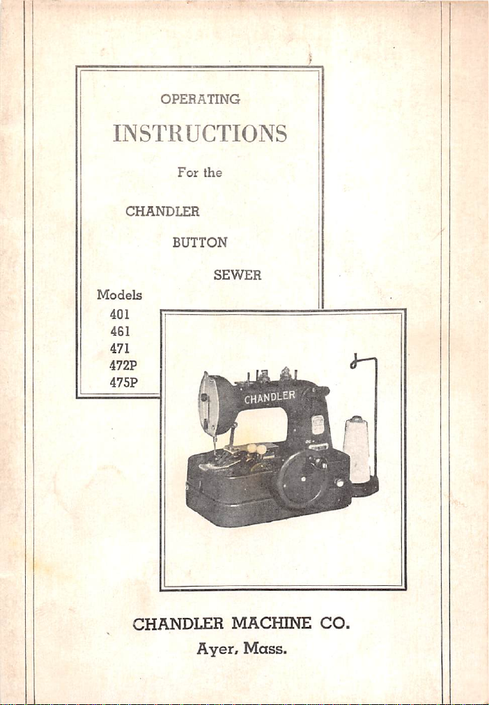
OPERATING
INSTRUCTIONS
For
the
CHANDLER
BUTTON
Models
401
461
471
472P
475P
SEWER
CHANDLER
Ayer,
MACHINE
Mass.
CO.
Page 2
KNOW
YOUR
MACHINE
Read
to fully
these
understand
instructions
your
carefully
machine.
and
thoroughly
Page 3
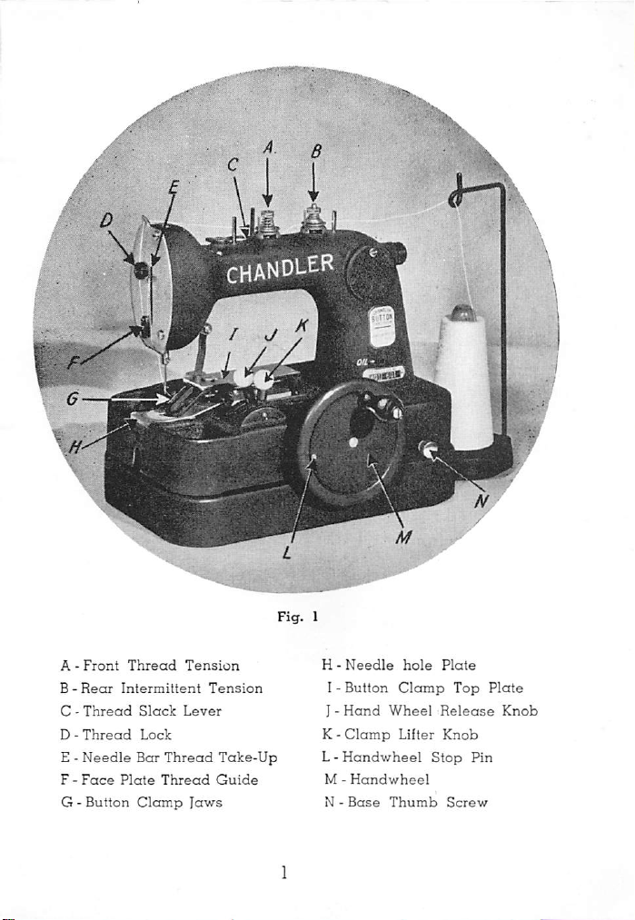
A -
B -
C -
D -
E -
F -
G -
Front
Rear
Thread
Thread
Needle
Face
Button
Thread
Intermittent
Slack
Lock
Bar
Thread
Plate
Thread
Clamp
chandler
Tension
Tension
Lever
Take-Up
Guide
laws
H -
Needle
I -
Button
J -
Hand
K -
Clamp
L -
Handwheel
M -
Handwheel
N -
Base
hole
Clamp
Wheel
Lifter
Thumb
Plate
Release
Knob
Stop
Screw
Top
Plate
Knob
Pin
Page 4
f-
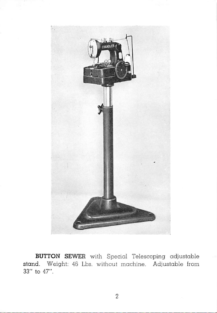
BUTTON SEWER
stand.
33"
to
Weight:
47".
46
Lbs.
with
v^ithout
Special
machine.
Telescoping
Adjustable
adjustable
from
Page 5
The
Chandler
erated
industries
machine.
hospitals,
It
will
from
the
pajamas,
The
Sewing
blocked
button
the
the
thread
The
cross
at
clamp
sewing
stitch,atthe
as
laundries,
hotels,
handle
smallest
coats,
the
to
on
the
over
{on a 4
very
Button
It is
purposely
coat
dry
cleaners,
either2hole
shirt
aprons,
cycle
is fully
completion
release
underside
cycle
consists
hole
endofthe
Sewer
button
etc.
of
the
button)
is a
designed
and
apron
etc.
or4hole
to
automatic,
the
material
of
the
of 12
cycle.
single
supplies,
that
used
sewing
automatically
button.
stitches,
and
thread,
for
buttons
the
cycle.
the
tieing, or
hand
use
institutions,
in
on
underwear,
flywheel
Raising
which
op
in
such
any
size
being
breaks
includes
locking
the
Double
button
lowering
releases
cycle.
Thread
upto12,000
clamp.
of
the
release
the
hand
The
button
controls
right
wheel
clamp
for
standinrearofmachine
yard
size.
are
located
hand
button
whereas
the
continuationofthe
to
controls
the
head
the
right
the
left
hand
provides
lifting
next
button
sewing
for
of
and
cones
the
Page 6
w
m
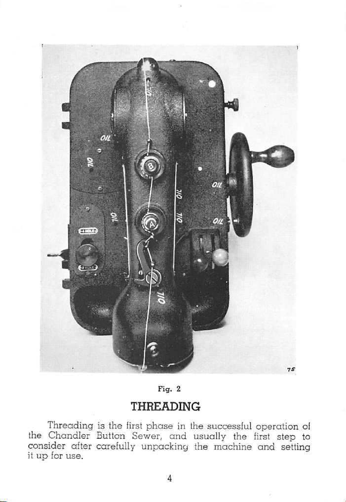
THREADING
Threadingisthe
the
Chandler
consider after carefully unpacking the machine
it UD
for
use.
first
phase
Button Sewer,
in the successful
and
usually the first step to
operation
and
setting
of
Page 7
Careful attention to the proper threading procedure is
most
importantinordertobe
by
the
machine.
Two views
threading
steps:
andtohelp
1. From
2.
3.
4.
5.
6.
the
pin
whichislocated
Passitbetween
the
tension
pin
locatedinthe
Carry
the
of
Pass
off
Then
over
the
LEFT of
the
little
thread
lever.
through
to the hole in
spool
are
herewith
makeitclear,
pin
post
thread
the
pininthe
through
front
the
assuredofperfect
shown
pass
the
thread
on
the
rear
tension
and
then
to
slotofthe
alongtothe
tension
slotofthe
the
guide
the
top
post
holeofthe
pin
of the face plate.
outlining the
we
outline
through
very
rearofthe
discs
the
RIGHT of
discs.
front disc
and
then
discs
and
performance
the
the
to
the
keeping
to
(sameas2).
thread
proper
following
first
guide
top
LEFT
the
the
RIGHT
slack
arm.
of
small
it to
pull
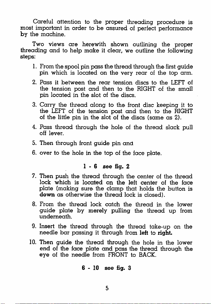
7.
Then
lock
which
plate
down
8.
From
guide
underneath.
9. Insert the
needle
10.
Then
endofthe
eye
of
1-6
push
the
thread
is
(making
as
the
plate
located
sure
otherwise
thread
by
thread
bar
passingitthrough
guide
the
face
the
needle
6-10
the
the
lock
merely
through
thread
plate
from
see
tig.
2
through
on
clamp
thread
catch
the
the
left
that
lockisclosed).
the
pulling
the
thread
centerofthe
thread
the
from left to right.
through
and
FRONTtoBACK.
see
pass
fig. 3
the
the
center
holds
of
the
in
thread
take-up
holeinthe
thread
through
the
button
the
up
on the
thread
face
lower
from
lower
the
is
Page 8
yj
Fig.
3
TENSIONS
There
are
only two
thread
tension adjustments,
both
are
at the top of the machine. The rear thread tension "B"
vFig.
1) is
an
light. (This
set
screw
do not
change
intermittent tension
rear
tension is locked in position
on
the
sideofthe
it for
thumb
adjusting
and
must
nut.
It is
tension on
be
by
means
"factory
the
thread.
kept
set"
very
of a
so
This
Page 9
rear
adjustment
stitch to
cone
of
keep
insteadofpullingupthe
The
iront
the
stitch
shouldbelight
until it
position
released.
thread
stops
you
lockonthe
Then pull the
onlyaslight
the
FIRST
merely
the
looper
tension
and
is
and
(hand
will
note
At
the
same
face
threadatthe
tension.
tension,
holds
the
the
"A"
from
(Fig. 1)
most
thread
stealing
loop
important
more
under
regulates
before
thread
the
button).
one.
the
the
This
canbedeterminedbyturning the
wheelisup
the
time
plateisopen
needletobe
When
"A",ahalf
rear
lower
tension
against
tension is
the
(center
is too tight,
turn
atatime
stop
pin). In this
raised
button
clamp
plunger
sure
it pulls free with
until
then
end
of a
from
the
tightness
tension
machine
and
thus
so
the
is loose).
loosen
thread
pulls freely through the needle. If too loose tighten it slowly.
the
button
If first
thread.
BE
tension
If
too
willbeloose,
SURE
YOU
"A"
is
too
tight
loose
the
knots
makingaloosely
MAKE
THESE
the
on
the
sewed
THREAD
looper
under
button.
TENSION
will
side
of
snap
the
AD-
lUSTMENTS ONLY WHEN THE HAND WHEEL IS BLOCKED
BY
THE
PIN
AND
THE
BUTTON
SEWING
Before the operator
control
as
button
(red
faraspossible so
lever on top of the
when
the
clamp
provided.
At
the
least
2V2"ofthread
IF
THEREISNO
THE
MACHINE
OF
THE NEEDLE, THE LOOPER WILL
THREAD
sewing
and
without
is lowered, the
same
time,
AND
the
even
can
color,
see
that
the
machine
the
projecting from
SLACK
machine
NO
IN
EXTRA
making
CLAMP
LOWERED.
PROCEDURE
sew
on a button, the right
Fig. 1)
thread
shouldbepulled
forward
slack pull off (see Fig. 1)
is kicked over to the left. Then
proper
operator
THE
will
go
a stitch. (See Fig. 3,
slack
must
the
THREAD
THREAD
through
see
eye
AT
NOT
in the
that
of
THE
FROM
CATCH
the
thread
thereisat
the
needle.
TOP
THE
full
cycle
Page
6).
hand
OF
EYE
THE
of
is
Page 10
BUTTON
The
button
clamp
small lever E, (Fig. 10,
plate
is to
set
the
openingofthe
you
may
use.
The
jaws
a
trifle
smaller
is
inserted,
and
thus
On
Page
23),
ment
clear
two
hole
hole
button.
thumb
screwsothe
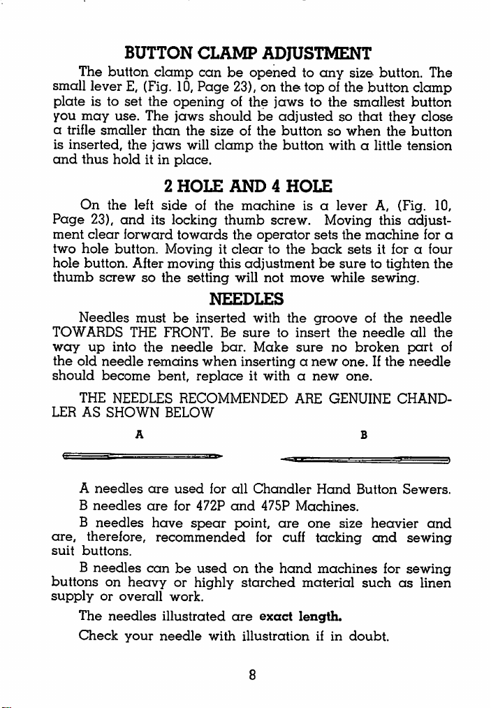
Needles
TOWARDS
way
up
the
old
needle
should
LER
become
THE
AS
the
SHOWN
than
the
jaws
hold
it in
left
and
its locking
forward
button.
After
must
THE
into
the
remains
NEEDLES
place.
2
HOLE
sideofthe
towards
Moving it
moving
be
FRONT.
needle
bent,
RECOMMENDED
BELOW
CLAMP
can
Page
ADJUSTMENT
be
openedtoany
23), on
the
jawstothe
should
the
sizeofthe
will
clamp
be
the
adjusted
button
button
AND4HOLE
machine
thumb
the
operator
is a
screw. Moving this
cleartothe
this
adjustment
setting
NEEDLES
inserted
Be
bar.
when
will
not
move
with
the
sure
to
insert
Make
sure
insertinganew
replaceitwithanew
ARE
size
button.
The
top of the button clamp
so
so
with
lever
smallest
that
when
a little
button
they
close
the
button
tension
A, (Fig. 10,
adjust
sets
the
back
sets
be
suretotighten
while
groove
the
no
broken
one.Ifthe
machine
it for a four
sewing.
of
needle
the
for a
needle
all
part
needle
the
the
one.
GENUINE
CHAND
of
A
B
B
are,
suit
buttons.
B
buttons
supply
The
Check
needles
needles
needles
therefore,
needles
on
or
heavy
overall
needles
your
are
used
for
are
for
472P
have
spear
recommended
canbeused
or highly
work.
illustrated
needle
with
all
Chandler
and
475P
Machines.
point,
are
for cuff
on the
are
hand
starched
exact
illustrationifin
8
material
length.
Hand
one
size
tacking
machines
Button
heavier
and
such
doubt.
for
Sewers.
sewing
sewing
as
linen
and
Page 11
THREAD
A
coneofthe
suggest
a soft
slippage
Chandler
stitches
usingastrong
thread
and
Button-Sewing
We
suggest
over
machineamuch
crowd
all
the
button.Afour
the
of
area
all
the
or
original
the
of
Use
sizes.
spacing
break.
We
button
the
buttons
Watch
may
button
material.
you
missed
the
a
wider
better
stitches
hole
pulling
where
out
is
greater
caution
proper
will
threadissent
glazed,
get
poor
stilches.
Thread.
BUTTONS
hard
results
Best
useof4-hole
area
on
chancetoworkasyou
between
button
on
the
oh,asthe
the
for
very
and
against
is a
shirt
two
good
and
buttonisheld
spacingofthe
largeorvery
may
the
finished
results
buttons.
the
selling
helps
cause
use
with
the
thread.Ifyou
and
experience
canbeobtained
They
material
and
are
holes
as
inatwo
point,itduplicates
eliminate
on
holesisthe
small
buttons
the
needle
of
cheap,
machine.
We
use
thread
with
spread
gives
not
trying
hole
the
danger
overawider
same
where
to
bend
low
price
the
the
to
for
bone or pearl buttons. These buttons have razor sharp edges
at
the
holes
and
making
The
holes
or
deflection
one
think
are
of
would
thereissomething
apttobe
the
needle.
cause
unevenly
the
thread
spaced,
wrong
also
to
cut
with
causing
and
the
break,
machine.
burring
TO
The
left
machine
this
the
but
repeat
this will
much
it.
for
button
buttonasecond
merely
the
Do
not
putintoo
thread
START
hand
control
the
next
sewing
forwards.Inthe
time,
pull
back
sewing
repeat
cycle.
this
many
that
the
needle
on
cycle
THE
button
cycle. To
event
do
not
the
blue
too
stitches
will
MACHINE
(blue, J Fig. 1)
release
that
you
pull
back
and
turn
oftenona
and
two
plug
releases
the
machine,
wishtosew
on
the
the
hole
the
holes
bendintryingtogo
red
button,
machine
button
with
through
the
pull
over
to
as
so
Page 12

ADDITIONAL
CLASS
INSTRUCTIONS
472-P
&
475-P
't
FOR
MACHINE
THE
Thisisdone
jaws.
strike
of
with
made
besttotack
nesses
the
Be
the
On
cuff
the
invisible.
For
of
light
fingers
extremely
CUFF
by
placing
suretospread
top
jaw
clips,
weight
rightinthe
off
material.
so
the
trousers
that
heavy
seam
seam.
TACKING
the
the
jaws
(See
Fig
the
The
the
tackisdrawn
trousers
where
cuff
under
so
that
A.).
tack
can
operator
or
there
the
the
be
can
into
extra
are
notsomany
regular
needle
made
spread
the
heavy
will
at
the
seam
cuffs
button
the
seam
and
it is
thick
not
top
Page 13

When
and
placeitunder
the
cuff
and
itself. This is
the
exact
catch
the
show
throughtothe
This
method
the
needle
tral
grey
trousers.
tacking off the seam, fold
the
jaws
so that the tack is
halfinthe
called
location
tackatthe
is
from
bending
thread
For
can
this
single
"blind"
under
tacking.Ittakes
the
edgeofthe
front of
preferrable
and
be
used
"blind"
cloth
jaw
the
cuff.
on
causing
regardless
tacking
back
the top of the cuff
thicknessofthe
practicetolearn
so
that
the
fold so that the
heavy
trouserstoprevent
thread
breakage.
of the color of
operation
made
operator
tack
(See
half in
trouser
will
will
not
Neu
the
Fig. B.).
In
the
stitches
Cleaners
BLIND
many
thisisvery
SEWING
cases
showing
it is
desirable
on
the
important
OF
to
underside
on
suit
11
A
BUTTON
sew
onabutton
of
coats.
the
cloth. To
without
some
Page 14

Fig.
C
(See
turned
Place
only,
sewing
show
than
halfway
some
will
take
be
successfully
and
suspender
under
Fig. C.)
underatthe
the
folded
or,inother
will
through
partofthe
a little
side
This
will
illustrateasuit
point
where
material
words,
under
under
thenbedoneinthe
the
into
of
material.
the
stitches
practice.
used
bands
the
material.
button
for
If
there
may
Onceithas
attaching
without
the
the
the
fold of
the
show
any
button
front
first
two
the
material
is a
slight
through.
been
buttons
stitches
coat
that
has
is to
be
attached.
half
of
the
holes
only.
cloth
and
will
is
inserted
possibility
This
operation
mastered,itcan
onto
suit
showing
been
button
more
coats
on
The
not
that
the
Page 15

INSTRUCTIONS
lor
TIMINa
THE
All
strictly
with.
The
that
must
that
have
their
machine
on
the
machine
Important
ADJUSTma
MECHANICAL
mechanical
alone,
and
following
replace
experienced
and
mechanical
is
properly
replaceable
the
end
settings
should
pages
essential
wish
settings
of
these
and
checking
SETTINGS.
should
not
be
are
only
be
tampered
for
partsorfor
troubleinoperating
to
double
to
see
adjusted.
Parts
illustrated
instructions
left
those
those
check
if
the
at
13
Page 16

(1)
Turn
thread
finger,
TAKE
(2)
Check
has
PARE
Make
(3)
Check
(4)
EXAMINE
PUT
TROUBLE.
(5)
WithaNEW
see
needle.
trouble.
sults. Poor
cut
needle.
the
machine
that
never
OUT
the
threadingofthe
not
jumped
IT
WITH
sure
the
your
YOUR
IN
WRONG
When
whether
Evenasmall
Try
qualityofpearl
the
thread
THREAD
may
be
over
wound
BREAKAGE
and
remove
around
any
the
loose
looper.
strands
Use
a screw driver. BUT NEVER LOOSEN OR
THE
LOOPER
outorwound
ILLUSTRATIONS
thread-pulls
thread
tensions
NEEDLEIFIT
SIDE
in
doubt
needleinyour
the
buttons
amount
other
typesofbuttons
and
unevenly
TO
REMOVE
machinetosee
around
through
as
outlined
IS
TO,
IT
WILL
always
putina
machine,
you
are
using
of
deflection
buttons
have
spaced
TIfflEAD.
that
the
thread
some
part.
COM
FIG.
2 &
FIG.
the
needle
smoothly.
previously.
BENT, BURRED, OR
SURELY
new
CAUSE
needle.
crankitslowly
are
deflecting
can
cause
and
holes
compare
sharp
that
the
edges
deflect
of
your
3.
to
the
much
re
that
the
In
the
experienced
suggestions:
1. LooF>er
loopertohook
(see
2.
Needle
(see
3.
Needle
(See
may
hole.
may
4.
Needle
(see
event
while
striking
paragraph
striking
paragraph
striking
paragraph
not
Clean
be
leftinthe
may
paragraph
NEEDLE
that
considerable
using
be
inserted
out
not
BREAKAGE
the
machine,
the
needle
the
needle
"Setting
finger,
finger
"Timing
looper.
Needle
"Setting
full
any
part
hole.
lineupwith
"Aligning
14
Needle
check
or
being
uponaslight
the
Looper").
may
the
finger").
Bar
the
Needle
depth
of
the
Button
into
an
holesinthe
Clamp").
Breakage
too
the
close,
is
following
causing
deflection—
be
out
of
time—
may
be
too
Bar"),orNeedle
the
Needle
old
needle
button—
being
low—
Bar
that
Page 17

5.
6.
Improper
Needle,
Clamp
Cams").
Needle,
any
other
Movement
may
not
be
needle
maybetoo
outofTime—(see
Genuine
short
paragraph
Chandler
or too
long.
"The
The
adjustments
ment
will
cause
no
thread
in
cause
end
TIMING
finger
the
the
of
trouble.
timingisone
machine.
machine
THE
An
to
IN
FINGER
improperly
break
thread,
of
the
most
important
set
finger
miss
stitches
adjust
and
This
view
shows
and
all
the
To
turn
made
proper
reveal
iurthest
check
the
from
Finger.
stroke.
this
machine
underneath.
direction
Needle
Note
adjustment,
over
(careful;
Finger
loosen
on
its
Rotate
not
Plate
pulled
position
the
base
hinges
the
machine
backwards)
as
away
at
clamping
this
adjustment
very
until
to
its
slowly
the
screw
in
finger
is
Page 18

cam
point,
the
the
1/16".
throws
plate
back
the
the
finger
so
that
curveofthe
See
Fig. 4
Cutaway
to
finger
should
the
and
Needle
itselfasfar
have
needle
finger
should
Fig. 5.
Fig.
view
showing
when
Fingerisclear
forwardasit will go. At this
gone
comes
5
beyond
down
clear
position of
the
toward
the
needle
Finger
Forward.
needle
the
hole
looper,
by
about
Should the finger go too far beyond needle, or not far
enough, loosen clamp screw 8, Fig. 6
correct
adjustment.
THE FINGER ADJUSTMENT.
needle
position,
tightening
THIS IS THE FIRST STEP
The finger must be
and
needle plate hole. Proper adjustment is when the
clamp
adjusted
and
screw
TO
sideways
move finger into
after
making
TAKE IN MAKING
the
in relation to the
needle is about 1/16" from the flat face or side of the finger.
(The curve at the front of the finger should center with the
needle
set
bly
lower
2nd STEPIN
plate
hole)
Should the finger
screw
holding the finger
need
sideway
bushing
adjustment, loosen the
and
tap
the
whole
in the direction desired, making certain that the
does
not
rideorcontact
THE
ADJUSTMENTOFTHE
the
hubofthe
cam.
FINGER.
assem
cam
fol
THIS IS THE
See Fig. 6
of
Page 19

5.
2.
3.
4.
1.
Thread
Finger
Finger
Cam
Rnger
Shait
Cam
Follower
Bushing
Follower
Spring
6.
Finger
Finger
7.
8.
Looper
Cam
Cam
Support
Follower
Clamp
Screw
Page 20

After
machine
needle
should
begins
fast,
bend,
If
up
past
of
the
To
the
finger
set
screws
controlled
proper
slowly
must
be
be
passing
to move-
the
backofthe
burrorscratch
the
finger
the
needle
finger
adjust
may
the
cam
h.old
by
this
positioning
watching
on
through
its
finger
upstroke
the
backward.
finger will hit
the
smooth
moves
according
the
too
slowly
plate,
the
snap
the
thread.
oscillationofthe
to
camtothe
cam.
THISISTHE
IN ADJUSTING THE FINGER.
To
repeat:
trolledbyadjusting
the
of
adjusting
ment
bearing
POSITION of finger to
cam
finger to
is
controlled
block.
finger
the
strokeofthe
cam
on
by
the
needle
Should
thread
the
shaft.
See
linger
and
needle
and
the
finger
the
needle
finger
the
needle
willbetight
finger,
adjustment
THIRD
Fig. 6.
as
shown,
very
point
of
plate
holeasthe
move
backward
causing
surface.
will
have
and
retard
required.
Timingofthe
OR
FINAL
the
needle
closely. The
the
needle
finger
needle
moved
the
or
advance
Three
finger
is
follower on finger shaft. TIMING
needleiscontrolled
main
moving
shaft. SIDEWAYS
entire
assembly
adjust
in
turn
too
to
hook
is
STEP
con
by
the
TO
TIME
Should it
that
the
looperisprovided
looper. The looper set screw must
this flat
timing of
needle
partofthe
There
and
are
the
looper.
the
AND
become
looper
SET
necessary
with
shank.
THE
to
replace
a flat
always
LOOPER
the looper, note
on
the
shank
bear
and
seat
of
against
two adjustments to consider in checking the
One
is in
otheristhe
relationtothe
distance,
18
sideways,
upstroke of the
from
the
needle
the
Page 21

The
hand
wheel
until
the
needle
scale
on the top
projects through the long slot in the faceplate) so that a
ing
may
be
obtained
faceplate) then
takeup
eye
has
point of the looper should
behind
relation
or
the
running
spotted
by
justing
the
needle
For
Class
between
retarding
back
the
of
the
through
on the shaftatthe factory,
anyone
these
other
machines.
should
barisat
its
sideofthe
(usually
continue
moved
(see
401
and
looper
small
machine.
the
to
5/32"
figure
461
and
spiral
This
upper
thanamechanic
be
turned
lowest
thread
in
the
proper
pointofstroke.
take-up
eye
direction
Place
(one
that
read
against
turn
the
the top
hand
edge
wheel
of
until
Upwctrd. At this position the
be
just
7).
machines
beginning
the
actual
to
show
"timing"
from
needleiscontrolledbyadvancing
gear
on
the
main
shaft
towards
gear
drives
armofthe
and
thoroughly
the
machine.
should
vertical
The
not
be
shaft
gear
moved
trainedinad
the
the
of
is
a
Page 22

For
Class
471
modernized)
the
retardingaseparate
on
the
front
endofthe
Two
small
set
sleeve
bearing
screws
after
the
justsothat
looper
the
In
very
(located
to
setting
and
on
supports)
time
the
proper
the
pointofthe
there
the
needle.
machine
actual
"timing"
looper
main
screws
inside
hold
looper,
adjustment
clearance
looper
is a
space
See
(or
holder
shaft.
on
face
this
Fig. 8.
previous
the
enlarged
of front
sleeve
securely
was
made.
between
about
of light
models
is
made
sleeve
in
retightening
looper
1/64"
between
that
have
by
advancing
attached
separately
shoulderofthe
bearing
place.
and
Loosen
the
and
needle,
from
the
needle,
the
pointofthe
been
or
disc
finger
both
screws
have
or
Fig.
8
IN
BE
SURE
CHECK
CHECKING
TO
THESE
THE
USE
A
SETTINGS
LOOPER
NEW
WITH
AGAINST
STRAIGHT
THE
NEEDLE.
A BENT NEEDLE IN THE
NEEDLE—
DO
NOT
MACHINE. MAKE SURE THE NEEDLE IS ALL THE WAY UP
IN
THE
NEEDLE
BAR
HOLE.
Page 23

SETTING
THE
e1
®
iJ
NEEDLE
The
needle
replacing
event
the
replaced
justment
tiontothe
The following
be
observed:
1.
Insert
way
bar
that
an
in
2.
Providing
properly
tion
the
ing
and
the
tion,
needle
mined
machine
point
ject
then
needle
top
needle
3/64")
edge
figure
BAR
bar
and
in
new
one
with
the
andinproper
other
mechanism.
pointers
new
needle
up
in
hole,
making
thereisno
old
needle
the
needle
the
timed
to
the
upstroke
needle
proper
behind
of
(see
pages
Set
the
height,
or
position
bar
by
until
just
beginstopro
raise
or
bar
the
turning
the
so
eye
is
below
of
the
looper
7).
may
such
must
proper
the
needle
part
stuck
hole.
looper
in
preced
"To
Looper")
is
the
needle,
lower
that
1/32"
the
need
an
be
ad
rela
must
all
the
sure
up
rela
Time
loca
of
the
deter
the
looper
the
the
of
the
(or
lower
(see
of
is
of
Page 24

3.
4.
Needle
is in
rub
on
and
down.
to
turn
Tighten
bar
must
line
with
the
sidesofthe
Otherwiseitmay
hard.
set
screwinneedle
beinlinesothat
the
slotinthe
slotasthe
face
bind
bar
thread
plate,
needle
causing
clamp
and
bar
stud.
take-up
does
moves
hand
eye
not
up
wheel
BUTTON
At
some
timeitmay
the
button
holes
In
clamptoaccommodate
in
buttons.
suchacase,
backwardsiscontrolledbyadjustment
and
marked
and
moving
the
clamp
machine
nut
after
The
"C"
towards
whereas
decreases
irjoving to
strokeofthe
onlyiscontrolled
first
cover.
stop
suretotighten
nut
Should
back
and
stop
BUTTON
At some time it
soasto
position
CLAMP
be
ADJUSTMENTS
necessary
larger
strokeofthe
button
in Fig. 10. Loosening
centerofthe
machine
movingittowards
the
strokeofthe
desired
by
greater
away
nut
may
the
the
button
position.
clamp
stop
sideways
nut
cross
from
securely
CLAMP
be
necessary
perfectlyinline
"B" Fig. 10,
strokebenecessary,
the
front of
after
ALIGNMENT
to
change
clamp
under
the
increases
the
clamp.
for
the
or
smaller
forwards
rear
cover
adjustment
outer
edgeofthe
Tighten
the4hole
stroke
stroke
adjusting
located
move
the
machine.
making
the
adjustment.
to re-align the clamp
with
the
spaced
and
plate,
nut
on
button
under
the
Be
needle.
The needle should enter the center of all holes without striking
the
sides
or
solid
part
of
the
hard
hole,
the
holeofthe
on
the
button
the
clampisoutofline
button
itself
with
and
button.Ifthe
must
bend
in
and
shouldbeadjustedtocenter
the
needle
as
order
outlined
needle
to
below.
enter
strikes
the
of
22
Page 25

mi
iWHjlTlI'OlWr11-'ir...
Fig.
10
Before
sure
any
adjustments
Omit
made
The
head
these
2
hole
needle
the
needleiscentered
proceeding
to
insert
a
BRAND
to line
threading
without
button
the
the
clampisheld
screws ''D" Fig.
screws
enters
button
just
enough
in
the
the
holeofthe
needle
thread
"*10
with
jaws
both
any
NEW
up
with a
so
being
at the
to
and
ways,
button
NEEDLE
that
in
the
firmly in
rearofthe
loosen
turn
button.
see
clamp
so
adjustment
as
not
crookedorbent
the
adjustments
way.
place
by2hexagon
top plate. Loosen
the
plate.
the
Move
Fig.10and
Then
machine
the
clamp
Fig.
to
make
needle.
can
insert
until
so
11.
be
be
the
that
a
Page 26

**
Then tighten
over
slowly
centeroithe
any
sideofthe
causing
needles.
missed stitches,
When you
both
holding
When
it
should
automatically
fc
by
this
hand,
other
hole,
are
screws.
clamp
Fig.
one
clamp
binding
m.aking
hole.Besure
otherwise
thread
assured
clamp is properly
adjustmentismade
line
up
24
11
sure
that
that
the
the
breakage
the
clamp
screw
needle
the
needle
and
and
needle
does
will
possibly
turn
be
adjusted
on
the2hole
for a 4 hole button.
1
machine
enters
not
touch
deflected,
broken
tighten
button
the
Page 27

has
does
of
the
The
cams
completed
not
begintomove
button.
THE
mustbeadjusted
its
shift
before
until
after
CAMS
so
the
that
needle
the
needle
the
enters
clamp
the
has
and
button
button
or
comeupout
These
cams
setting, turn the
At
this
point
the
or
be
opposite
frame.
AUTOMATIC
In
the
top
the
automatic
Function
in first
BEFORE
To
shaft
left
not
drop
the
to
room
set
paragraph
The
proper
the
advance
of
hand
move
or
the
machine.
sideofmachine
cam
outoftension
The
cam
3rd,
holditwith
adjust
backwards
for fingers, so
screw
and
are
setatthe
hand
wheel until it is blocked by
lineonthe
the
line
arm
of
releaseofthe
of
this
automatic
under
timing is
needle
bar
retard
sideways,
this
A
post.
has3set
screw
and
cam
adjusted
factory
outer
rimofthe
stamped
on
TENSION
the
machine
rear
intermittent
"Tensions."
when
the
reaches
timing
hole
for
close
as
screws.
driver,
by
otherwise
Loosen2and
and
forwards.
mustbeheld
accordingly.
buttodouble
cam
the
edgeofthe
RELEASE
is a
Cam
tension
B—^Fig.
tension
threadisreleased
its
highest
adjust
screw
the
turn
Space
by
point
the
Cam
driver
Arm
the
release
machine
does
screw
is
hole
after
check
the
should
their
stop pin.
match
machine
that
controls
1.
is
described
5/32"
of stroke.
on
the
located
cover.
pin
will
loosening
handwheel
not
allow
driverin3rd
top
on
Do
to
make
When
make
thread
thread
cam
is
release
release
loose—turn
late
earlier.
or
25
handle
turn
in
operating
handwheel
direction
backward
to
Page 28

BS-93-W
BS-95-T
BS-93
BS-I44-B
f)
BS-35
BS-97
BS-I44-A
¥
BS-)69
BS-163
BS-96
BS-166
Page 29

BS-
BS-
BS-
BS-
93W
93
94
95
Thread
Rear
Rear
Front
Tension
Thread
Thread
Tension
PARTS
Tension
Tension
Stud.
UST
Release
Washer.
Release
Release
Stud.
Pin.
BS- 95T
BS-
97
BS- 96
BS-144A
BS-144B
BS-
35
BS-
169
BS-163 Button
BS-166
Thread
Thread
Thread
Thread
Thread
Cam
Needle
Button
Tension
Tension
Tension
Tension
Tension
Roller.
Set
Clamp
Clamp
Spring.
Bottom
Top
Thumb
Thumb
Screw.
Lifter Lever
Lifter
27
Disc.
Disc.
Nut—Front.
Nut—Rear.
Spring.
Lever
Lock
Spring.
Page 30

cn
o ^
V^ip*
Page 31

BS-
88
Needle
Hole
PARTS
Plate.
LIST
BS- 99
BS-105
Thread
Needle Bar Thread Guide
BS- 122 Button
BS- 47
BS- 48
BS- 82
BS- 181
BS- 44
BS-160
Thread
Thread
Hand
Stop
Thread
Thread
Slack Take-up Lever.
Clamp
Jaw Spring.
Finger.
Looper.
Wheel Stop Pin.
Arm Spring.
Finger
Finger
Cam
Follower.
Cam
Follower Spring.
and
Take -up
29
Page 32

SOLt**'
MRkaP
'
*»>
CHANDLER
A
large
supplyofspecial
convenience
have
difficultyinsecuring
A
special
general
6M
and
Prices
We
thread
Button
of
our
soft
mercerized
repairingisstocked
12M
yd.
conesinblack
and
thread
also
stockalarge
which
Sewing
mustbeused
Machine.
andisstockedinthree
khaki.
Prices
on
application.
CHANDLER
Manufacturers
of
many
SEWING
customers,
color
This
different
Ayer,
the
Famous
sewing
the
thread
in 2000
card
supply
with
is a
MFG.
Mass.
threadisstocked
especially
proper
for
yd.
and
white.
mailed
of
the
Chandler
special
sized
conesinwhite,
COMPANY
CHANDLER
THREAD
thread.
darning,
spoolsin32
on
application.
special
Hand
glazed-finish
for
those
mending
colors
Button
DARNER
for
Sewing
Operated
thread
black
the
who
and
and
and
Page 33

> -CHANDLER
A
complete
at
any
location
A
flexible
FEATURE
edgeofthe
be
expanded
The
Chandler
can
alsobeused
You will find
winter
not
when
well
It
pays
big
Manufacturers
socket
li'ght
table
the
lighted,
dividends.
SAVE
to fit a
Light
Chandler
unit
which
the
operator
attached
adjustment.
by
means
although
on
other
this
lightisweak.
by
all
EYESTRAIN
Write
CHANDLER
of
Sewing
clamps
finds
to a
The
ofanadjustable
table
withamaximum
designed
typesofsewing
light
indispensable
means
—
for
current
MFG.
AVER,
the
famous
Light
on
any
convenient,
flexible
for
If
your
NEATER
price.
COMPANY
CHANDLER
sewing
arm
unitisheld
the
equipment.
on
sewing
most
complete
orderaChandler
DO
MASS.
machine
gives
clamp
thickness
Chandler
rainy
WORK
DARNER
DOUBLE
which
Darner
days
equipment
Light
table
to
can
of 2".
or in
todayl
the
is
Page 34

CHANDLER
^
4-
4
4
DARNING
FLUTING
HAND
SEWING
AND
MACHINES,
OH
POWER
THREADS
MENDING
HAND
BUTTON
MACHINES
OH
POWER
SEWERS
4 REBUILT TAILORING
4
PLEATING
4
RUFFLE
4
CUFF
4 LABEL
MACHINES
IRONERS
TACKERS
TAGGERS
MACHINES
1
 Loading...