

Page 1

I
400 VETERANS BLVD, CARLSTADT
NJ
07072
Page 2

Page 3
u
Page 4

Page 5
CONTENTS
1.
MAIN
PARTS
2. SPECIFICATIONS··········································································································································1
3. WORK TABLE AND MOTOR ........................................................................................................................ 2
4.
INSTALLATION·············································································································································3
4-1:
Installing the rubber hinge and the corner rubber····
4-2.
Installing the oil pan··· ...... · ...
4--3. Installing
4-4.
installing the spool pin ... ······· .... ···· ... · .....
4-5.
installing the knee lifter
4-6.
Installing the belt······
4-7.
Installing the bobbin winder
4-8.
Installing the belt guard{L)· · · · · · · · · · · · · · · · · · · · · · · · · · · · · · · · · · · · · · · · · · · · · · · · · · · · · · · · · · · · · · · · · · · · · · · · · · · · · · · · · · · · · · · · · · · · · · · · · · · · · · · · · · · · · · · · · · · · · · · ·6
4-9.
Installing the thread
4-1
0.
Lubrication···················································
4-11.
Checking the machine pulley rotating direction··
5. PREPARATION BEFORE SEWING .................................................................................................................. g
5-1.
Installing the needle····
5-2.
Removing the bobbin case············
5-3.
Winding the
5-4.
Installing the bobbin case· .. · ..
5-5.
Threading the upper
5-6.
Adjusting the stitch
6. SEWING······················································································································································12
6-1.
Sewing················································································································································12
6--2.
Backtacking·························································-·······
7 .THREAD TENSION···································· ........ ·········· ...... ··········································································
7-1.
Adjusting the thread tension·· .....
7-2.
Adjusting the presser foot
8.STANDARD ADJUSTMENTS········································
8-1.
Adjusting the thread controller
8-2.
Adjusting the height
8-3.
Adjusting the feed dog position (longitudinal)···· ..
8-4.
Adjusting the positions
8-5.
Adjusting the timing the needle
8-6.
Adjusting the height
8-7.
Adjusting the timing between the needle and hook
8-8.
Adjusting the clearance between rotary hook and opener (thread release
Adjusting the clearance between feed forked connection
8--9.
8--10. Adjusting the height
s-·11. Adjusting the presser foot
8-12.
Adjusting the timing
8-13.
Adjusting the
9.SAFETY CLUTCH MECHANISM···· .............................................................................................................. 25
NAMES································································· ..................................................................
........
the machine
lower
thread················-
length·································
L0d
regulator···········································-··············
···········
··
..
······
....
·········
.....
··············
head···············
assembly··············································································································
..
····
..
···
..
..
···················
stand············
..
··
..
··
..
········
········································
thread·············································
pressure·····················
spring···················
of
the feed dog· .....
of
the needle
of
the needle
of
the presser
movement
of
the vibrating presser foot ...
... ······
..
·················
···················
··············
················
with
bar·····································································································
..
················
.. · ..
··············································
..
·············
.... ·
........
.......................................................................................................
and
feed
feet····················:···························
..
················
..
..
··
..
···
..
··· ...... ···· ......
·················
.........
·········
......
···········································································
needle hole
...................................................................................................
amount·······························································
..
···· ... ···
.. ·
..
· · · · · · · · · · · · · · · · · · · · · · · · · · · · · · · · · · · · · · · · · · · · · · · · · · · · · · · · · · · · · · · · · · · · · · · · · · · · · · · · · · · · · · · 7
···············
..
·····························
..
········································
··········
.....................
..
··············································································14
..
································
······························
of
the feed
......................................................................................
and
·······
..
····
....
··
..
·····
..
··· ..
················
..... ···
..
···················
.. · ..
······················
..
···
..
··············
·····················
..
··········
..
··
... ·
..
·······
....
···········
..................
.........................................................................
.....
···························································
····························································
dog··················
feed fork
..
·····································································
..
..
·····
..
···
..
··············
..
····
..
···· ...... ···
..
···············
················································
...
finger)···············································
collar··················································
........................................................
...... ·
..
··
..
···
..... ·····
··
..
················································
..
·····································
······················
..
······ ...... ···
..
···· .... ·· ...... ····
....
·······································
..
·······································
···························
..
···············································
·········
...
····································
...
···············
.....
···········································
..
..
· .... ···
··· ...
..
······
.... · ..
..
··
....
··············
..
················
..
··
..
··················
···············
..
··········
..
···················
..
...
·········:.·
...............
·······
... ·
..
.. · .. · ..
..
··········
..
··
..
················11
..... ····· ·13
···· ..
......
···
·········22
..
·· .... ·· ·3
·········
···· ·3
....
..
·········
.... ···· ·9
······11
···13
..
···15
······15
··
···21
··· ·5
..
·1
·13
·14
·16
·18
-19
·20
·21
·23
-4
·5
·6
·8
·9
10
12
18
24
-1
·3
-4
0
Page 6
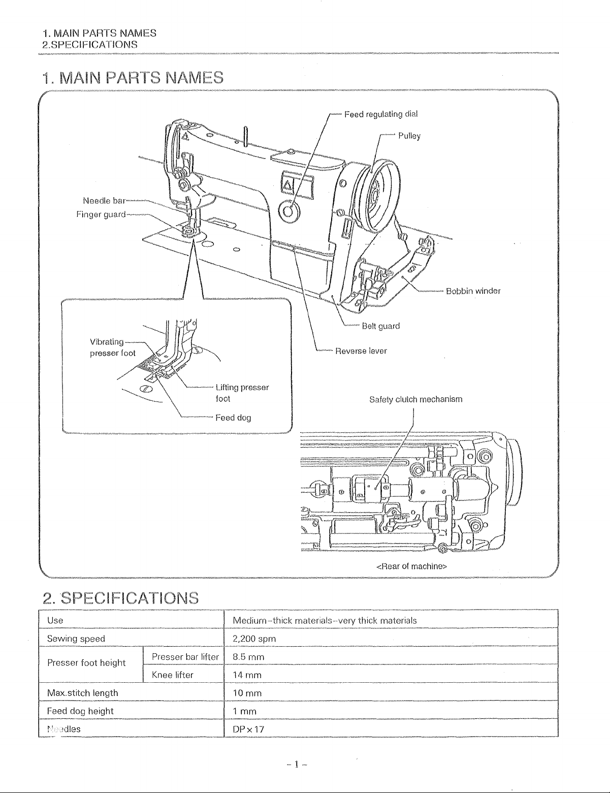
1.
MAIN PARTS NAMES
2.SPECIFICATIONS
1"
MAIN
Feed regulating dial
Vibrating
presser foot
~-
lifting presser
foot
-~Feed
dog
Safety clutch mechanism
of
<Rear
materials--very thick materials
machine>
-
1-
Page 7
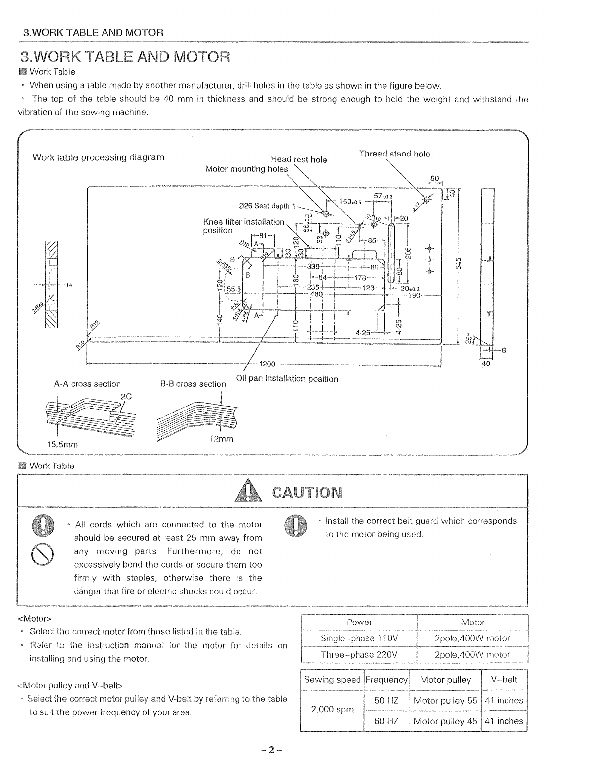
3.WORK TABLE AND MOTOR
3.WORK TABLE AND MOTOR
Work Table
• When using a table made by another manufacturer, drill holes
• The top
vibration
of
the table should be 40
of
the sewing machine.
mm
in
thickness and should be strong enough to hold the
in
the table
as
shown
in
the figure below.
weight
and withstand the
Work
table
processing
14
A-A
cross section
diagram
B-B
cross section
Motor mounting holes
!<:nee
lifter installation
position
Oil pan installation position
Head
Thread stand hole
15.5mm
Work Table
• All cords which are connected to the
should be secured at least 25
moving
any
excessively bend the cords or secure them too
with
firmly
danger that fire or electric shocks could occur.
<Motor>
• Sek;ct
<M0tor pulley and
UiG
correct motor from those listecl
f{,:Jfor
to
the instruction manual for the motor for details on
installing and using the motor.
V-belt>
Select the correct motor pulley and V-belt by referring to the table
to
suit
the
power frequency of your area.
parts.
staples, otherwise them
Furthermore,
mm
in
the table.
motor
away from
do
not
is
the
• Install the correct belt guard which
to the motor being used.
Power
50
HZ
Motor
pulley 55
2,000 spm
60HZ
Motor
pulley 45
Motor
motor
41
inches
41
inches
-2-
Page 8
4.
INSTALLATION
4.
INSTALLATION
o The sewing machine should only be installed
by a qualified technician.
• Ask your dealer or a qualified electrician for any
electrical
· The sewing machine
The installation should be
more people.
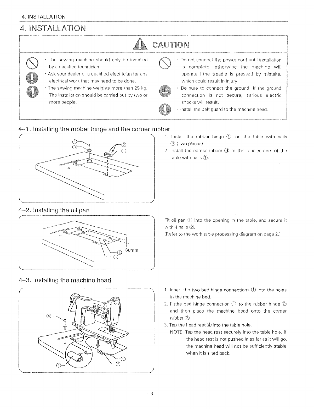
4-1.
Installing the rubber hinge and the corner rubber
4~2.
Installing the oil pan
work
that may need to be done.
weights
carried out by
more than 29 kg.
two
or
o Do not connect the
is
complete,
oper8te ifthe treadle is
v;hich could result in injury.
Be
sure to connect the ground. If the ground
connection is not secure, serious electric
shocks will result.
• Install the belt guard to the machine head.
1.
Install the rubber hinge
(2
(Two places)
2.
Install the corner rubber Q) at the four corners
table
with
nails
power
otherwise
(1)
cord until installation
the
m8chine
prEJSSt)cl
on the table
by mistake,
with
will
nails
of
the
4-3.
Installing the machine head
Fit oil pan
with
4 nails
(Refer to the
1.
Insert the
in
the machine bed.
2.
Fitthe bed hinge connection to the rubber hinge
and then place the machine head onto the corner
rubber
3.
Tap the head rest into the table hole.
NOTE:
into the opening
work
table processing diagram on page
two
bed hinge connections
Tap
the head rest securely into the table hole. If
the head rest
the machine head will
when
it is tilted back.
is
in
the table, and secure it
not pushed in
not
be sufficiently stable
CD
into the holes
as
far
as
it will go,
2.)
--
3
Page 9
4.
INSTALLATION
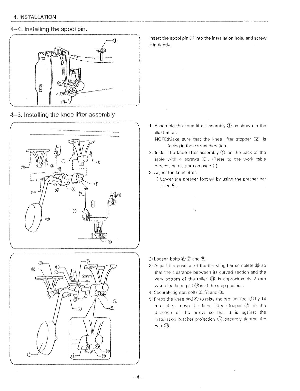
4~4.
Installing the spool pin.
4-5.
Installing the knee lifter assembly
Insert
the
spool pin
it
in
tightly.
1.
Assemble
illustration.
NOTE:Make sure that the knee lifter stopper
facing
2.
Install
the
table
with 4 screws
processing diagram on page 2.)
3.
Adjust
the knee lifter.
1)
Lower
lifter®.
CD
into the installation hole, and
the
knee lifter assembly
in
the correct direction.
knee lifter assembly
the
presser
foot @ by
as shown
CD
on the back of
(Refer
to
the
using the presser bar
work
screw
in
the
fZ:;
is
the
table
2)
Loosen bolts
3)
Adjust
the
position
that
the
clearance
very
bottom
when
the
knee pad
4)
Securely tighten bolts and
G)
Press the knee pad
mm;
then
move
direction of the
installation bracket projection
bolt@.
-4-
@.(1)
and
(til
of
the thrusting bar complete ® so
between
of
the
roller @ is approximately 2
(9)
the knee lifter stopper
arrow
its curved section and
is
at the stop position.
to
mise the presser
so that it
is
@,securely
foot
!f
:z
against
tighten
the
mm
by 14
in
the
the
the
Page 10
4.
INSTALLATION
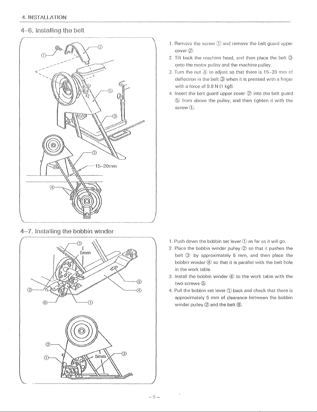
ling thH belt
1.
Remove the screw
cover
2.
Tilt back the rnachine head, and then place the belt
onto the
3.
Turn the nut to adjust so that there
deflection
with
4.
Insert the belt guard upper cover into the belt guard
screw
motor
in
a force of 9.8 N
from above the
(1)
and
romove the belt guard upper
pulley and the machine pulley.
is
the belt Q)
when
it
is
pressed
(1
kgf).
pulley, and then tighten it vvith the
15-20
with
a finQer
mm
of
4-7.
Installing the bobbin winder
1.
Push down the bobbin set lever
2.
Place the bobbin winder pulley so that it pushes the
belt by approximately 5 mrn, and then place the
bobbin winder
in
the work table.
3.
Install the bobbin
two
screws
4.
Pull the bobbin set lever
approximately 5
winder pulley
@ so that it is parallel
winder@
@.
GJ
mm
of clearance between the bobbin
(2)
and the
belt®.
as
tar
as
it will go.
with
the belt hole
to the
work
table
with
back and check that there
the
is
Page 11
4. INSTALLATION
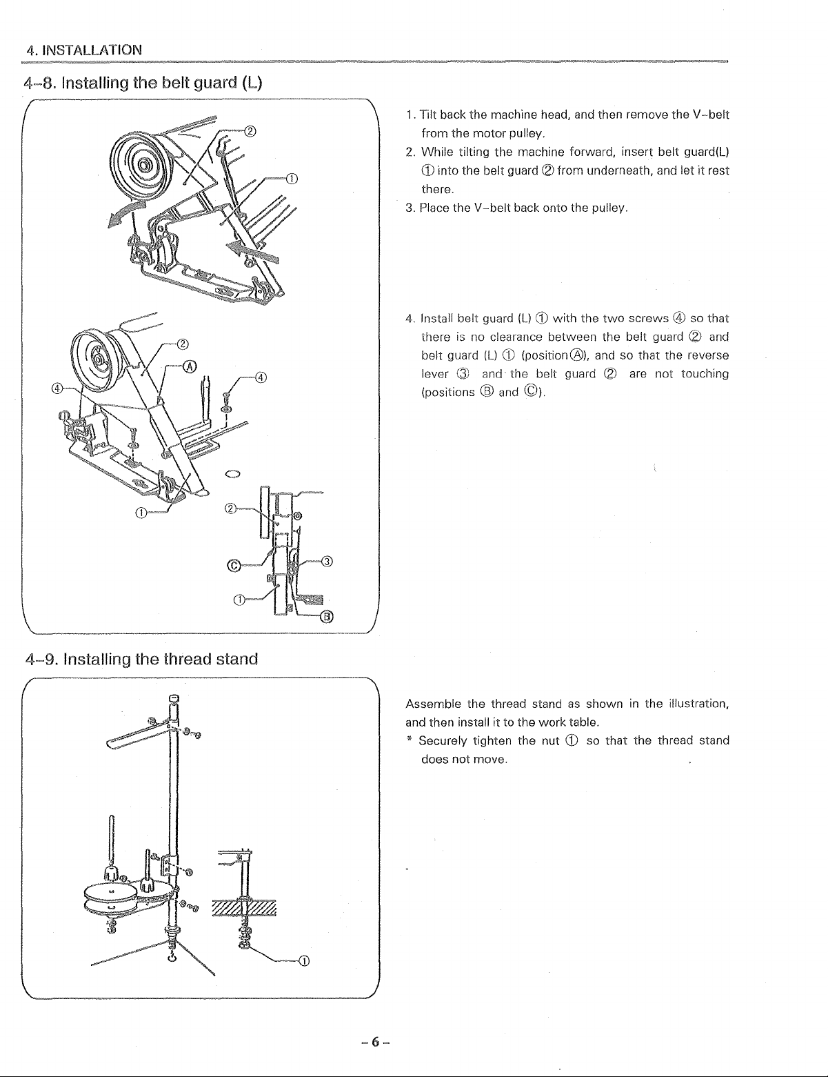
4~8.
Installing the belt guard (L)
1.
Tilt back the machine head, and then remove the
from the
2.
While tilting the machine forward, insert belt guard(L)
G) into the belt guard
there.
3.
Place the
4.
Install belt guard (L) G)
there is no clearance between the
belt guard (L)
lever @ and the belt guard
(positions
motor
pulley.
V-belt
back onto the pulley.
G)
(position@), and so that the reverse
@ and ©).
(2)
from underneath, and let
with
the
two
screws @ so that
belt guard
(2)
are
not
(2)
touching
V-belt
it
rest
and
4-9.
Installing the thread stand
Assemble the thread stand
it
to the
and then install
work
* Securely tighten the nut
does not move.
as
table.
CD
shown
so
that
in
the illustration,
the thread stand
Page 12
4. INSTALLATION
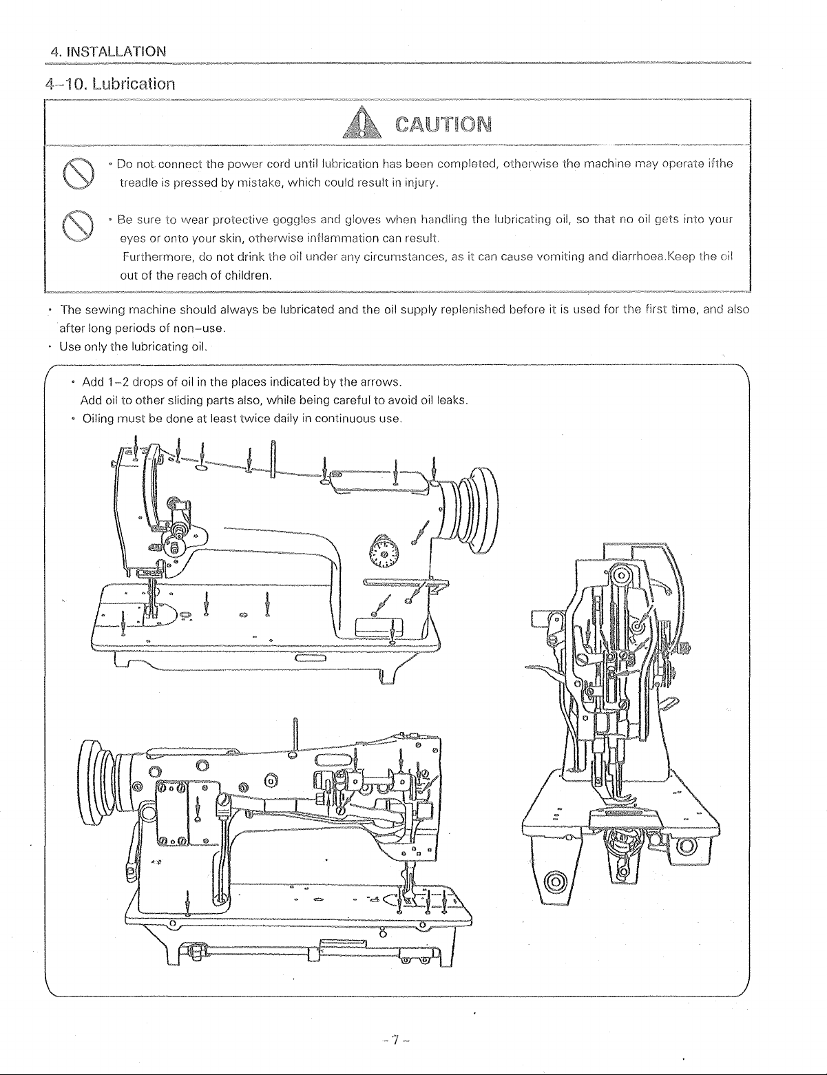
4-" 10. Lubrication
•
Do
not
connect the
treadle
•
Be
eyes or onto your skin, otherwise inflammation can
out
is
sure
to
Furthermore, do not drink the oil under any circumstances,
of
the reach
power
cord until lubrication has been completed, otherwise the machine may operate ifthe
pressed by mistake, which could result
vvear protective goggles
of
children.
and
gloves when handling the lubricating oil, so that no oil gets into your
in
injury.
result
as
it can cause vomiting and diarrhoea. Keep the oil
The sewing machine should always be lubricated and the oil supply replenished before it
after long periods
Use only the lubricating oil.
•
Add
1-2
Add oil to other sliding parts also, while being careful to avoid oil leaks.
Oiling
must
of
non-use.
drops
of
oil
in
be done at least
the places indicated by the arrows.
twice
daily
in
continuous use.
is
used for the first time, and also
-7-
Page 13
4. INSTALLATION
II
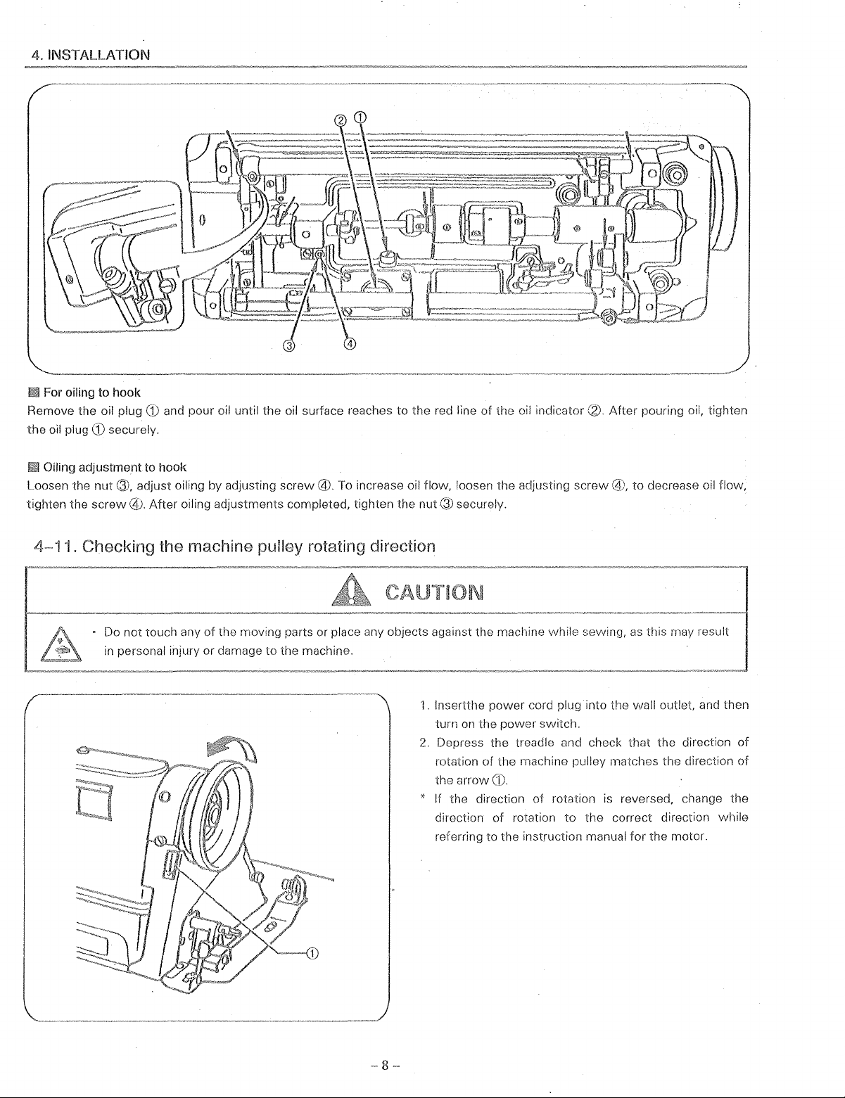
For oiling to hook
Remove the
the
oil plug
oil plug
CD
securely.
CD
and pour oil until the oil surface reaches to the red line of the oil indicator
\2).
After pouring oil, tighten
Oiling adjustment to hook
Loosen the
tighten the
4~
nut®.
adjust oiling by adjusting
screw@.
After
oiling adjustments completed, tighten the
screw@.
To increase oil flow, loosen the adjusting
11. Checking the machine pulley rotating direction
Do
not
touch any
in
personal injury or damage
of
the moving parts or place any objects against the machine while sewing,
to
the machine.
screw@,
nut®
securely.
1.
lnsertthe
turn
2.
Depress the treadle and check that the direction
rotation
the arrow
* If the direction
direction
referring to the instruction manual for the motor.
power
cord plug into the wall
on
the
power
switch.
of
the machine pulley matches the direction
CD.
of
rotation
of
rotation
to
the correct direction while
to
decrease oil flow,
as
this may result
outlet
is
reversed, change the
and then
of
of
-8--
Page 14
5.
PREPARATION BEFORE SEWING
5.
PR
5-1
PARATION BEFOR SEWING
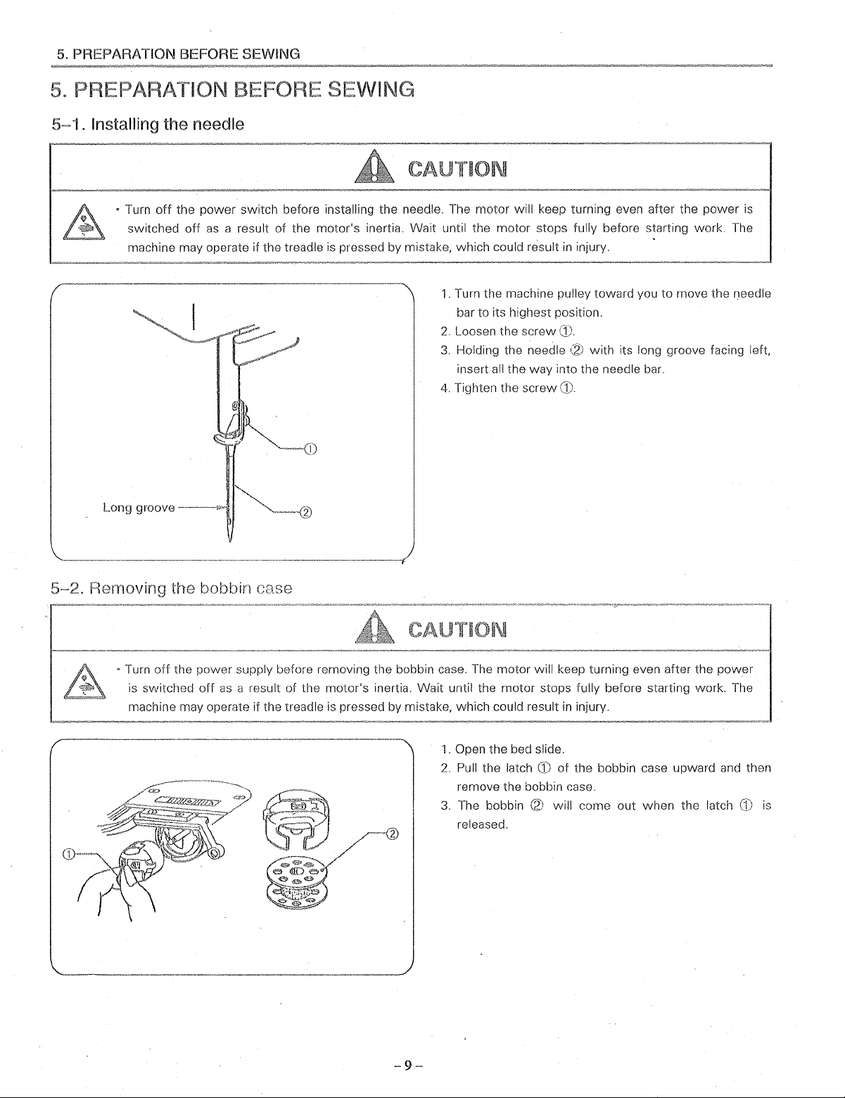
. Installing the needle
• Turn
off
the
power
switch before installing the needle. The
off
as
switched
machine may operate if the treadle
a result
of
the
motor
motor's
inertia. Wait until the
is
pressed by mistake, which could result
1.
Turn the machine pulley toward you to move the needle
2.
Loosen the
3.
4.
Tighten the
motor
bar to its highest position.
Holding the needle
insert all the way into the needle bar.
will keep turning even after the
stops fully before starting
in
injury.
screw(!).
(2)
with
its long groove facing
screw
CD.
left
Long
5-2.
R£~moving
groove-
~
the bobbin case
• Turn
off
the power supply before removing the bobbin case. The motor will keep turning even after the
is
switched
machine may operate if the treadle
off
as
a result of the motor's inertia. Wait until the
motor
is
pressed by mistake, which could result
1.
Open the bed slide.
2.
Pull the latch
remove the bobbin case.
3.
The bobbin
2
released.
power
stops fully before starting work. The
in
injury.
CD
of
the bobbin case upward and then
(2)
will come
out
when
the latch
CD
is
-9-
Page 15
5.
PREPARATION BEFORE SEWING
5~3.
Winding the lower thread
• Do not touch any
as
this may result
of
the moving parts or place any objects against the machine while winding the lower
in
personal injury or damage to the machine.
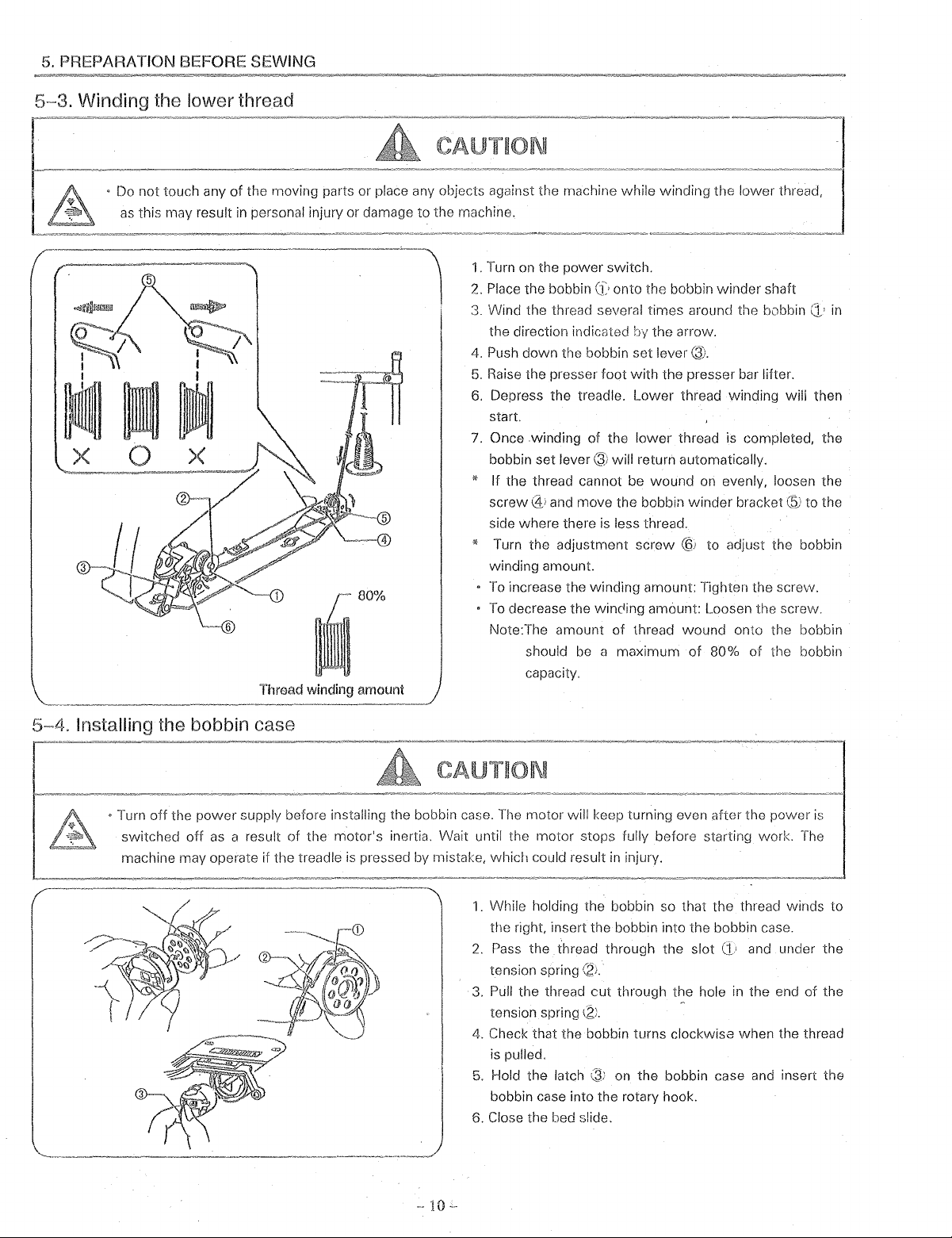
1.
Turn
on
the power switch.
2.
Place the bobbinG:· onto the bobbin winder shaft
3. Wind the thread several times around the bobbin
the direction indicated the arrow.
4.
Push down the bobbin set lever Q).
5.
Raise
Thread winding amount
the presser foot
6.
Depress the treadle. Lower thread winding will then
start.
7.
Once .winding of the
bobbin set
lever®
* If the thread cannot be wound
screw@_~
side where there
* Turn the adjustment screw
winding amount.
To
To
Note:The amount of thread wound onto the bobbin
and move the bobbin winder bracket to the
increase the winding amount: Tighten the screw.
decrease the wincing amount: Loosen the screw.
should
capacity.
be
with
the presser bar lifter.
lower
thread is completed, the
will return automatically.
on
evenly, loosen the
is
less thread.
@j
to adjust the bobbin
a maximum
of
80% of the bobbin
<1·
in
5~4.
Installing the bobbin case
• Turn
off
the
power
switched
machine may operate if the treadle
off
supply before installing the bobbin case.
as
a result of the motor's inertia. Wait until the motor stops fully before starting work. The
is
pressed by mistake, which could result
The
motor will keep turning even after the power
in
injury.
1.
While holding the bobbin so that the thread winds to
the right, insert the bobbin into the bobbin case.
2.
Pass
the thread through the slot
tension spring
3.
Pull the thread
tension spring
4.
Check that the bobbin turns clockwise when the thread
is
pulled.
5.
Hold the latch
bobbin case into the rotary hook.
6.
Close the bed slide.
\21.
cut
through the hole
(2:.
;.3;
on the bobbin case
and
in
the end of the
and
is
under the
insert the
Page 16

5.
PREPARATION BEFORE SEWING
5-5.
Threading
• Turn
switched
machine may operate
the
upper thread
off
the power supply before installing the bobbin case. The motor will keep turning even after the power
off
as
a result of the motor's inertia. Wait until the motor stops fully before starting work.
if
the treadle
CAUTION
is
pressed by mistake, which could result
Turn the machine pulley and raise the thread take up lever
G:·
before threading the upper thread. This will make
threading easier
at
the sewing start.
out
in
injury.
and
it will prevent the thread from coming
is
The
5-6.
Adjusting
the
stitch
length
Stitch length
can
Ci·.
Numeric figures on the dial
mm. The desired numeric figure
set at just above, while depressing the revers lever
slightly.
-11-
be set by turning the feed regulating dial
i.l'
show the stitch length
on
the dial should
be
in
Page 17

6.
SEWING
6.
6~1.
Sewing
"
Attach
"
Turn off the
When
When
When
• Do
all
attached, injury rnay result.
off
JS
a result
rnayoperate if the treadle is
threading the needle
replacing the needle and bobbin
not
not
touch any
personal
injury
devices bofor:1
powe;
switch
of
the
using the machine and
of
the
or
damage
Lower thread
at the
motor's
moving
to
the
inertia.
by mistake,
when
parts
or
machine.
rnachir18. If the rnachine is used vvlthout these devices
times. The
Wait
until the rnmor
leaving
place any objects against
motor
will
which
could
msult
the
machine unattended
1.
While
the machine
thread
2.
Pull the
out
smoothly,
3. Turn on
4. Depress the treadle
slops
turning evon
fully before
in injury.
the
machine
holding
comes
lower
the
power
after
while
sewing,
the
upper thread
pulley by hand
out
onto
the
thread
toward
switch.
to
start
the; pnvver
vvork. The rnachine
as
this may
with
your
toward
feed
you
sewing,
you
dog.
and check
is
sv\'itchcd
fingers, turn
until the
that
lower
it
pulls
6~2.
Backtacking
When
the reverse lever
direction
original position,
normal.
will
be reversed, and
-12-
the
feed
is pushed,
when
direction
the
it
is returned
will
change back
material
feed
to
its
to
Page 18

7.
THREAD TENSION
7.
THREAD TENSION
7 ~ 1.
Adjusting the thread tension
Upper thread
Lower thread
Good even stitches
Upper thread tension too weak or
too strong
lower
thread tension
Lower thread
Upper thread tension too strong or
too weak
II
Upper thread tension
of
The tension
tension thumb nut
To
increase the tension
tension thumb nut
turn the tension thumb nut
II
Lower thread tension
the upper thread
G).
of
the upper thread,
(f1
to the right.
<}1
to the left.
CAUTION
Turn
off
the
power
switch before removing or
inserting the bobbin case.
The motor will keep turning even after the
power
motor's inertia. Wait until the motor stops
fully before starting work. The machine may
operate if
which could result
is
switched
the treadle is pressed by rl'istake,
in
injury.
lower
thread tension
is
adjusted using the
To
decrease tension,
off
as
a result
·~urn
the
of
the
Adjust by turning the thread tension
case will not drop by its
of
the bobbin case is held.
so
that the presser foot can properly hold down
7
~2.Adjusting
the presser foot pressure
---------.
coming out
Adjust the presser foot pressure to
possible
material by turning the
-
13-
own
screw
weight
(f•.
nut
(2J
until the bobbin
while
lower
the thread end
as
much
as
Page 19

8.
STANDARD ADJUSTMENTS
8.
STAN ADJUSTMENTS
Maintenance and inspection
machine should only be carried out by qualified
personnel.
Ask your dealer or a qualified electrician
out
any maintenar.ce and inspection
electrical
If
original positions and check that they
correctly before using the machine.
8-1.
Adjusting the thread controller spring
systern.
any safety devices have been rernoved,be
sure
to
m-install
of
the sewing
to
carry
of
the
them to their
operate
power cord from the wall outlet at the
times, otherwise the machine may operate if
treadle
in
even after the power
the motor's inertia.
fully before starting work.
When carrying out inspection,
maintenance
When replacing consumable parts
rotary hook
If the
carrying
careful to observe
Operating range
The standard operating range for spring
1.
Loosen the
troller spring stop ~ to adjust the operating range.
• For more operating range, move the spring stop
the right.
• For less operating range, move the spring stop
left.
2.
Tighten the
is
injury. However, the motor will keep
power
out
screw
screw
by mistake, which could
is
switched
Wait until the
switch needs
some adjustment. be
all
safety precautions.
of
spring
\2·,
and then turn the thread con
to
(2_:.
off
be
CD
as
left
is
a
5-1
on
Omm.
~~?!
Qi
to the
to
-14-
Tension
The standard tension for spring
1.
Loosen the tension
2.
Turn the tension stud (§l to adjust the tension.
To
stud
To
3.
After adjustment, tighten the tension thumb nut
screw\!?).
of
the spring
is
0.39-0.78
thumb
nut
\4;
and
screw@.
increase the spring tension, slightly turn the tension
®!counterclockwise.
decrease the tension, turn the stud clockwise.
N (40-80g).
0\)
and
Page 20

8. STANDARD
8~2.
Adjusting the height of the feed dog
ADJUSTMENT~;
8~3.
AdjUsting the feed dog position (longitudinal)
The maximum height
of
the needle plate
of
height
1.
2,
3.
4.
the feed dog:
Tilt the machine head away from you. Turn the pulley to
raise the feed dog to its highest position.
Loosen the
Raise or lower the feed dog
Tighten the
screw~.
screw
of
the feed dog from the surface
(2)
is
normally 1 mm.
Q
..
CD
as
necessary,
To
adjust the
31.5mm
1.
Change the feed amount to the smallest possible
setting.
2.
Turn the pulley to raise the feed dog
position.
3.
Tilt the machine head away from you.
4.
Loosen the screw (2), and then move the feed rock
~'
to
shaft crank
32.1
mm
from the edge
of
center
5.
Securely tighten the
the needle hole on the feed dog
adjust so that there
of
the needle plate to the
screw
CZ·.
to its highest
is
a distance
(1•.
of
-
15-
Page 21

3.
WORK TABLE AND fvlOTOR
3.
VVmk
Table
using a table made manufacturer, drill holes
When
The
top
of
ihe
table should be 40
of
vibration
the sewing machine.
mn1
in
thickness
and
in
should
the table
21s
shown
in
bG
strong to hold the
the below.
Thread
and
withstand the
15.5mm
.,
.,
"'""'
cross section
. Oil pan installation position
-16-
Page 22

8.
STANDARD ADJUSTMENTS
3~4.
Adjusting the Positions of the needle and needle hole of the feed dog
Needle
--
eclle
ter
hole
Turning the pulley to lower the needle bar
check whether the needle descends to the center of the
of
needle hole
If the needle does not enter into the center
1.
Remove the cover and loosen the screw
2. Holding the needle bar rock frame
required to get the correct position to the feeder.
3.
Tighten the screw
the feed dog or not.
((2
and close the cover.
;Ji
of
12.·
move it
slowly,
the hole:
slightly.
as
may
be
-Feed
dog
-17-
Page 23

8.
STANDARD ADJUSTMENTS
J'
A
I o;us
t'
mg
timing
tl1e
needle with
It
is
important that the tirning relationship
needle on its
movement
the
needle on the
start
When
procedure to change
1.
Clla:1ge the feed
2.
Loosen the
for oil resc-::voir
and the
3. Normally put the
ditch
4.
Turn the machine pulley
its
lowest
5.
And, pushing
cam and
feed dog
6.
After
positioning completed, tighten the each
securely.
downward
is
maintained at all tirnes.
downward
the
amoum
screw
Q,
oil reservoir
arrow
of
arm
shaft
point.
the
reverse lever up and down, turn
set
this atthe point both
rest
stroke and the · feed dog
rhe feed dog moven1ent
to the largest possible setting.
for cover
and then l"ernove the cover plate
mark
to
the
between
When
the scart
stroke reaches the top
must
use the following
the
mm
screw
the
up
screw
from
'~i
of
the
needle at 1
the
and
earn on
needle and the
the
of
V
the
Adjusting the height of the
<Needle
bar
highest point>
Needle plata
neeclle
When the needle bar
the measurement
plate and the upper end
1.
Loosen the
the needle bar 0
2.
Tighten the
screw
to
screw
G.•
is at its highest point, normally
between
\2' and
get
the
surface
of
the
needle eye is 22.3mm.
move
the setting posi tion
the correct posi tion.
of
the
needle
of
-
18-
Page 24

8.
STANDARD ADJUSTMENTS
8-7.
Adjusting the timing between the needie and the hook
After setting the needle bar height, set stitch length to
minimum, turn the machine pulley toward you
needle bar reaches its
allow the needle bar to raise about
upward stroke. With
of
the sewing hook should be at the center
and normally, the measurement between the hook point
and the upper end
further the
needle hollow should
*If
they are not measured
adjustments below.
II
Adjusting the timing
1.
Loosen the three set screws d
2.
Turn the hook shaft (2; to align the hook point
center
3.
Tighten the three
timing
Adjusting the
1.
Loosen the
2.
Move the hook to the right or to the left
require.
clearance between the hook point and the
of
the needle.
of
the sewing hook.
two
* Please note one
of
ditch
ditch during adjustment.
3.
Tighten the
hook shaft. Therefore, keep the
two
lowest
needle bar
of
the needle eye should be 2.4mm,
be
point. Continue turning
2mm
in
this position, the point
about 0.02 to
0.1
as
above, perform the
'·
set
clearance
screws
of
the
screws
screws
Q·
slightly.
two
~;.
screws
(,3)
and
is
until the
and
while on its
of
the needle,
mm.
with
the
re-check
placed on the V
screw
as
the
may
on V
-19-
Page 25

8.
STANDARD ADJUSTMENTS
8-~~8.
Adjusting
t11e
Clearance between rotary hook and opener
(Thread release finger)
0
L~
The opener facilitates the passage
loop by
rotating movement
instant opens a clearance gap between the notch
inner hook and the tab
needle thread loop to be drawn easily through the gap.
BCiearance between the opener and projection
1 . Loosen the
2.
3. Tighten the screw securely.
slightly nudging the inner hook creating a slight
of
it. This
of
the hook retainer
screw
(1).
Adjust the clearance between projection
~'
and the opener
releasing shaft bushing
may
be
required. The standard clearance between the
two
parts
is
0.7-0.9mm.
by means
@ to the right or to the left
of
the needle thread
movement
permitting
of
movernent
at that very
of
of
hook.
of
hook
of
thread
the
the
as
B Position
Place the one
ditch
B Adjustment
1.
Turn the machine pulley until the opener
projection
2.
Press the opener
make the right side
the bobbin case holder and tab the hook retainer
0.4-0.6mm.
This adjustment can be done by loosening the
3. Tighten the screw
of
the opener cam:
of
of
the hook shaft.
of
of
hook
screws
operation:
~)
(:1·
J_l
securely.
I_Q)
which
is
indicated by "S"
'.3:
extremely on its travel.
to
the projection
clearance
between
of
the notch on
presses the
hook (2: and
screw
01~
V
(§;
-20-
Page 26

8.
STANDARD ADJUSTMENTS
8~9.
Adjusting the cleare.nce between feed forked connection and feed fork collar
Incorrect clearance between the fork
collar
<2'
connection and feed fork
lenoth
or
overheating, etc.
1.
Remove the cover plate
2.
To
increase the clearance, loosen the nut
,(2;
to
the nut
This adjustment should be done
machine
3.
Upon completion
screw
left
pulley toward you to get correct clearance.
(9).
·:3;
or counter-·clockwise.
of
adjustment, tighten the
will bring irregular stitch
and the oil
of
feed forked
reservoir~~'"
CQ;
and
turn
with
turning the
screw
and
8-,1
0.
Adjusting the height of the presser feet
The standard height for the lifting presser foot
mm
when
the presser foot has been raised by the presser
bar
lifter(!.).
1.
Loosen the
then loosen the set
2.
Move the lifting presser
height.
3. Tighten the
4. Tighten the
pressure. (Refer to page 13.)
NOTE: If the height
screw,<~,
screw@.
screw
changed, the movement amount
presser
vibrating presser
movement
to page
raise the presser bar lifter
screw~~).
foot
(2)
up or
down
(,_1)
to
adjust the presser
of
the lifting presser foot
foot·~)
and vibrating presser foot 0 will
Adjust the amount
foot ~ so that it matches the
of
the lifting presser foot (Refer
21.)
of
movement
to adjust its
of
~)
(L;,
the
is
of
8.5
and
foot
is
The
-21-
Page 27

8.
STANDARD ADJUSTMENTS
8~
i 1 .Adjusting the presser foot movement amount
Movement
lifting presser foot
amount
for
Movement
vibrating presser foot
amount
for
Vibrating presser
move up and
Normally,
foot
motions.
• The maximum height
lifting presser
If changing the
presser foot and vibrating presser
use method
only one (thereby decreasing the
use method (8).
Method (A):
amount for both the
presser foot
1.
Loosen nut
2.
Move nut
(Raise the
decreasing motion.)
3.
Tighten the nut
down
vibrating presser
(::;'
operate to the same height
(A);
Simultaneous adjustment of the movement
'~J
nut
foot
alternately.
foot
(2;
movement
if increasing the
lifting presser foot and
(3).
up or
down
for increasing motion; or
and lifting presser
foot
of
vibrating presser
is 5.0
mm.
amounts
as
suitable to the work.
Q\
movement
and lifting presser
in
their vertical
foot
of
both the lifting
foot
simultaneously,
movement
amount for
of the other).
lower
vi
foot
and
brating
it for
(ZJ
4
Method (B): Adjustment
vibrating presser foot
1.
Loosen the vibrating presser bar
the presser bar lifter
2.
While holding the vibrating presser
bolt
1§.:
and then move the presser
as
necGssary.
3.
1-\ftt1r
4.
Tighten the vibrating presser bar screvv
-22-
of
the movement amount for the
screw
•J;ii.
foot
foot
the vibrating presser
@:,
and lower
G , loosen the
up or
down
foot
Page 28

8.
STANDAHD ADJUSTMENTS
8--1
Adjusting the timing of the vibrating presser foot
lifting presser
<When the needle lowers>
Feed
dog
<When
I l
I \
'-;-~~~~,
~~\
foot\--~
the
\ '-.._
\
needle
raises>
Needle
Check the vibrating presser
1.
Lower the presser bar lifter lever, then turn the pulley
At
toward you.
should reach the feed dog before the needle eye does.
2.
When the needle
presser foot
vibrating presser foot rises while
penetrating to the material, it may cause skipped
stitches, etc.
this time, tne vibrating presser foot
is
still holding the material firmly. If the
foot
timing
as
follows:
is
raised, make sure the vibrating
the needle
is
still
Feed
dog
If the timing is not correct
adjustments:
1.
Loosen the
2.
To synchronize the timing
turn the cam
3.
Tighten the
two
screws
C:Z).
screws():.
G_.
..
of
after
you make these
the vibrating presser foot,
-23-
Page 29

8. STANDARD ADJUSTMENTS
8·~
13, Adjusting the feed regulator
If the stitch length
same, make adjustment
1.
Remove the arm rear cover plate
2.
Turn the cover plate
holding upward the reverse lever.
3.
When the mark
rod
<5J
are
alignment, stitch length
will
be
same.
4.
Turn feed regulator rod 0 to the arrow
length
of
reverse is bigger and stitch length of forward
smoller.
5.
Turn feed regulator rod
length of reverse
bigger.
6.
After adjustment,tigthen the
of
forward
of
feed regulator.
\{;;),
of
feed regulator and feed regulator
(g)
is
smoller and stitch length
and
loosen the screw
of
to the arrow
screw
reverse
forward
·JJ.
and
"X"
"Y"
of
forward
are
not
with
reverse
, stitch
,stitch
is
is
-24-
Page 30

9.
SAFETY CLUCH MECHANISM
9.
with
If the thread is
stop the
flelease the
lovver shaft and lot the safcNV clutch
clutch
the rotary
mechanisrn
clutch mecl1anisrn
as
rnentionFJcl
below.
the
the rotary
hook
c1nd
opmatcs
to
off
the
Turn
the
povver
T!1o
machine may operate
power
is
switched
switch
off
before
as
a result the
if
the treadle is mistake, which could result
motor's
clutch rnechanisrn,
inertia.
Wait
until the
1.
Remove the thread, etc. entangled
NOTE:
2.
Slowly turn
button and the safety clutch mechanism returns
original position.
Do
not
hook,
the
The
motor
motor
v,;ill
stops fully before vvork.
in
injury.
with
the
use a
sharp-edged
as
doing so may damage the hook.
machine pulley
tool
while
to
pressing push
rotary hook.
clean the
to
the
Adjustment
If the safety clutch should
spring tension, use the following procedure:
1.
Depress
with
pulley
2.
Tilt back the machine head. Hold the safety clutch (left)
the
3.
To
screw
4.
Upon completion
At
safety clutch
the
your
strongly so that the
and turn the safety clutch (right) until you can see
screw
strengthen the tension
to the right, while
to
the same time, turn
-25-
of
spring tension
become
button in
left
hand.
0 through the hole
the left.
of
re-engages.
the
At
the
to
adjustment, depress
the
of
safety clutch
necessary
bed plate
same time, turn the machine
safety
clutch disengages.
of
spring turn the
lighten
the
tension, turn the
machine pulley until the
to
of
the machine
the
button
adjust
screw
Page 31

THREAD
LATE
13
2
-26-
Page 32

NO.
f--··
I B!9451 l FACE PLATE
']
4
,.
J
6
7 B8040 SCBE\'i' 9/M x 40 L"'8.0
8
9
!0
II
12
13
14
15
16
17
]"
0
19
20 B28206
21
22
23
24
25
26
27
28
29
30 B10690
31
32
33
34 BI80S5
35
36
37
38
39
40
41
42
43
44
45
46
47
-~
PAHT
'-----·~
BR09~
Bl0700
Kl052
B10551 I
nl9452
Bl5054
I
Bl0683
Bl95JO
Bl0759-A
Bl0760
B
1942 i C·--A
Bl9421
I
Bl951l
Bl079l
Bl9531
Bl9532
Bi9533
B!95l3
BI0793
Bl0678
Bl9422
B19512
Bl0689
Bl0694
BBI18319
Bl9534
B8100
B\9518
Bl5062
Bl9501
B18030-S 1 NEEDLE
B6031·-02
B18032C
B6034 I BED SLIDE SPRING
B6035 2 SCREW 3/32 x 56 L=2.7
B18495
B37254 2
B19455 1
B10703
Bl2384
Bl0709
B30046
NO.
~-
··-
l SCHEW 9/64 X 40
l P0:11Tl0\J PfN
l SCHE\V 9/64 x 40
OlLGUAHD
l
I
I
l
I
!
l
l
l
I TENSION
T.\KE~UP
TllHF\D
TIWEAD
I
I
SCHEW 9/61 x 40 L"'6.5
I
Tl!HEAD
THHEAD
I
TENSIO~~
LF:VEH CO\'EH
GUIDE: (UPPER)
GUIDE (MIDDLE)
GiJtDE (LOWEH)
GUIDE
BHACKET
BHACKET
I TENSION STUD
I TENSION
2
l
THHEADDISC
TENSION HELEASE WASHER
BHACKET
1 TENSION SPRING
l TENSION
l
TENSION
THUMB
THUMB
I TENSION RELEASE PLUNGEH
I TENSION HELEASE
2
]
I
I
1 SCHEW 3/32 x 56 L=6.0
1 TENSION
I
1 SCREW 9/64 x 40 L=6.5
J
I
1
1 TENSION RELEASE
2 SCHEW
1
1 EDGE
SCH.EW
THREAD
THH.EAD CONTROLLEH SPHING
THREAD
THHEAD
SCH.EW
THREAD
SCREW 11/64 x 40 L=8.5
BED
SCHEW M4 x 0.7 L=8.0
AH.M
9/64 X 40
CONTROLLEH STUD
CONTH.OLLEH DISC
THUMB
CO
NTH OLLER SPRING
11164
HETAINEB
PLATE
11164
SLIDE COMPLETE
GUIDE PLATE
CAP
1 WASHER
1 SCHEW 3/16 x 32
1
1
SPOOL PIN SCHEW 7/32 x 32
EARTH
WIRE
PARTS
L:o:4.5
FELT
COMPLETE
PIN
NUT
STOPPER
NUT
LEVER
NUT
STOP
x 40
Loo=l4.0
LEVEH
ROD
x 40 b::8.5
SCREW M4 x 0.7 L=4.0
NA:vtE
-----~-----~
'
-
-27-
Page 33

-28-
Page 34

ARM SHAFT, THREAD
TAKE~-U
R
NO.
1 B8009
2
PAHT
Bl0724
NO.
.Qty
l SCREW 15/64 x
I
OILING
3 B 18003C I TIJHEAD
4
5
6
7
8
9
10
11
12
13
14
15
16
17
18
19
20
21
22 B18486 l
23
24 B18008
25
26
27
28
29
30
31
32 B19528C I
33
34 BJ7041
35
36
37
38
39 BJ7015C
40
41
42
43
44
45
46
47 B19505
1310527
Bl8003
I\!0528
Bl5026
BI0728
Bl9504
BI0724
fll0726
B10523 l NEEDLE
B19418
B19417 l SCREW
Bl9414
Bl9416
B19415
Bl0563
Bl8006
BI7R6
BI0725
B19508
BI0579
Bl0725
Bl9508
B23637
Bl9503-A
BI9503-B
BI9503-·C
Bl9521
B!0827
B23637
B10723
Bl70l7C
1317018
Bl7019
l
1
I
1
l i OILING
l
I
I
1
1
j
TAKE-UP
THREAD
NEEDLE
TAKE-UP
I
OIL
PACKING
OILING
OILING
scrmw
NEEDLE
I SET SCREW
1
1
I
POSITION SCREW
WASHER
ARM
I SCREW 15/64 x 28 L=12.0
I
2
1
j
l
l
2
I
I
l
I FEED
2 SCREW 1/4 x 40 L"'7.5
2
l
1 OILING
1
OILING
LIFTING
SCREW
AHM
SCHEW 15/64 x
OILING
ARM
SCHEW
AHM
AHM
ARM
FEED
SCHEW 1/4 x 28 L=7.5
OILING
AHM
I POSITION SCREW
l SET SCREW 1/4 x 40 L:::7.5
I GEAH COVEH COMPLETE (UPPEH)
BJ7016
Bl7013
Bl0579
Bl3081
Bl8470
Bl0576
Bl0579
2 SET SCHEW 9/64 x 40
l
AHM
1 SCREW 15/64 x 28 L=20.0
1
I
1
OILING
BALANCE
POSITION SCHEW 15/64 x
I SET SCREW 15/64 x 28 L=20.0
1 SCHEW 3/32 x 28
PAHTS
NAME
28
L=
7.5
WICK
TAKE-UP
LEVEH
TAKE-UP
BAH
LEVEH
WICK
\VICK
WICK
BAH
1/4 x
114 x 28
BAR
SHAFT
FELT
ECCENTRIC
114
x 40
SHAFT BUSHING (MIDDLE)
FELT
SHAFT BUSHING COLLAR
l/4
x 28 L=7.5
SHAFT (STANDAHD
SHAFT
SHAFT
LIFTING
DHIVING
FELT
FELT
SHAFT GEAH (SPIHAL) COMPLETE
SHAFT
FELT
WHEEL
LEVER
HINGED
LEVEH
CONNECTING
DRIVING
STOP
CONNECTING
28
L=4.5
L=6.5
CRANK
114
x 28
l/4 x 28
BUSHING (FRONT)
L:~5.5
28
L=20.0
(lR"
MACHINE)
MACHINE)
(25
"
CAM
ECCENTHIC COMPLETE
HETAINEH
114
BUSHING (REAR)
L=
11.0
COMPLETE
STUD
LINK
STUD
SCREW 5/16 X 28 L=6.0
LINK
L=l4.0
L=20.0
MACHINE)
x 40 L=8.0
L=
10.0
28
L=21.0
STUD
.:..
29-
Page 35

NEED
BAR ROCK FRAM
-30-
Page 36

,N
NO.
I
1
3
4
5
6
7
H
9 i
lO
11
12
13
14
15
16
17
18
19
PART
BI0557
B19509 l
Bl0556 l PI\ESSEH
Bl072R l
Bl0728
I
Bi95l7
l l
"'_,,
J.(u)y·
BHYc
I
.\Yy
Jn47U
BI9412C
Bl7104 1
Bl9515 I
Bl9516 I
Bl9514 I
Bl0514
B19420
Bl9419 I
Bl0775
B12136 I
NO.
. ;\
..
1
I
20 B10774
21
22
23
24
25
Bl7114
Bl8485
B37215 l
Bl704l
Bl00446
26 B34712 l
27
28
29
B1761l
B37134
Bl9426
30 Bl9429
31
32
33
B34723 I
B37134
B30078
34 Bl9413
35
B6035
36 RB140553
37 Bl0533
38
39
40
41
BNOI22
Bl
1876C
lll
1877
Bll876
42 Bl0581
43
Bl7048-A
B17048-B
Bl7048-C
44
45
46
B6026-02
Bl9409
Bl8017
47 BI80J8
48
49
50
51
Bl9408
B34722
B34721
B8100
52 Bl0728
Qty
l
I
i
i
!
l
2 LIFTING
l
l HINGE SCREW 7/32 x
LIFTING
LlFTlNC BELL C!L\i\K
OILING
I
~,~~:
l.:'l\AtE
VJ
1
F!U·.s:;F:l{
YfBlL\TlNG
VlBH
PINCH
HINGE
NUT
LIFTING
BELL
CRANK
BAH
CO\\;E(~TINC
\VICK
1
~~
;~~~~
.J/,
TL\r·
l
BAH
.,.,
0 X ,_o
l'H'•'''"FH
\y
L,5J
EXTENSION
Led
'W;
.L
\\
>t,\.
PHESSEH
-\TfNG
PHESSEH
SCREW
SCREW
11/64 x 40 L"'6.0
1/4 x
114 x 28
ROCK
SHAFT
ROCK
SHAFT
PINCH SCREW 1/4 x 28 L=l6.0
CONNECTING
CRANK
WASHER
1
1 NUT7/32 x 32
1 LIFTING
CONNECTING
ECCENTRIC
COLLAR
WASHER
I
I
l NEEDLE
!
I NEEDLE
1
2
2
l
1
1
l
I
1
1
I
l
I
I
1
1 NUT9/32 x
I
I
I HINGE
I
I
I
2
I
OILING
SCREW 15/64 x
HINGE
PINCH
OILING
POSITION
SCHEW
FELT
STUD
BAR
SCREW
BAH
WICK
BHACKET
M4
x 0.7
28
ROOK
M4
CONNECTING
L=
WASHEH
NEEDLE
BAR
SCREW 3/32 x 56 L=2.7
SCHEW
NEEDLE
NEEDLE
SLIDE
SLIDE
HINGE
SCREW
ARM
ARM
ARM
1/8
x 40
BAH
THREAD
DP x 17
BLOCK
COMPLETE
BLOCK
SCREW
7/32 x
7/32 x 32 L=7.0
SHAFT
(STANDARD
SHAFT
(18"
SHAFT
(25 " MACHINE)
L=4.5
#22
28
CONNECTION
CONNECTION
PINCH
VIBRATING
VIBRATING
SCREW
OILING
SCREW
SCHEW
PRESSER
PRESSER
9/64 x 40
WICK
ROD
9/32 x
1/4 x
L=6.5
Ui\K
6.0
B'
P '•'XTE'''""0·'
I
1\..
_\.
L..c
BAR
FOOT
28
BUSHING
32
CONNECTION
L=8.8
FHAME
x 0.7
L=lO.O
10.0
GUIDE
32
MACHINE)
MACHINE)
28
28
L=-17.5
BAR
BLOCK
BAR
BLOCK
PARTS
NAME
LE\K
.....
~,...._)l_
SPHlNG
COi\lPLF:TE
STUD
GUIDE
1
.!_'\
-31-
Page 37

PRESS R BAR,LIFTING PRESS R FOOT
((?~/
I
36
37
/34
32
7\
8
\
~&
\
33
16
-32-
Page 38

RESS
BAR, LIFTING
PR
RFOOT
NO.
I
I B8043
2
3 B9406
4
5
6 B8478
7 B9518 i
8
9 B8479 1 PRESSER
10
11
12
13
14
15
16
17
I8
19
20
21
22
23
24
25
26
27
28
29
30
31
32
33
34
35
36
37
PART
B6729
B0538 1
B5999 1
B4828 1
B0547
B0546-A I
B0659
B9405 I
B8085 2
B8477 I
B0796
B8483
B9403
B18080-A I
Bl8080-B I
B18080-C I
B0548-A
B9408 I
B5111
NO.
Qty
I
I PnESSEH
2
SCREW
SCHEW
PHESSEH
SCHEW
1
PHESSEH
PINCH
SCREW
SCREW
1
SPRING
'f!i:NSION
1 PRESSER BAll LJFTEll
HINGE
SCHEW
SCREW
PRESSER
l
I
1
1
I
LIFTING
SCREW
HINGE
SCREW
ARM
SHAFT
ARM
SHAFT
ARM
SHAFT
BRACKET
PINCH
SCREW
PIN
B6026 I PRESSER
B9519 I
B9404 I
B384
B359-A l
B360
B808! I
B8862
B0539-A l
B4717
B4718
B4719
B6287
B0601
·2
134720
1
2 NUT3/16x
I
l
l
l
2
2
PRESSER
PH.ESSER
HINGE
SCHEW
LIFTING
LIFTING
KNEE
LIFTEH
PHESSEH
LIFTING
LIFTING
LIFTING
WASIIEH
SCHE\\T
SCHEW
M6
xI
L=IO.O
BAH
POSITION
15/64 x 18
BAH
M6
BAH
BUSHING
x 1
L=6.0
POSITION
L=1
11/64 x 40
1 lt64 x
40
BAR
LIFTING
HELEASE
SLIDE
3116 x 32
11/64
x 40
L=8.5
BAH
PHESSEH
FOOT
9/64 x 40 L=9.0
114 x 28
(STANDARD
MACHINE)
(18
"
MACHINE)
(25
"
GUIDE
BLOCK
1/4 x 28
BAR
SPRING
BAH
SPRING
BAR
SPHING
15/64 x 28
LEVEn
CONNECTING
32
LEVER
BELL
BELL
BELL
M5
M6
BAH
x 0.8
x l
BELL
BUSHING
CHANK
CHANK
CHANK
L=12.0
CONNECTING
CRANK
bc!O.O
PARTS
GUIDE
1.0
(UPPEH)
GUIDE
BHACKET
1=:14.0
BRACKET
MACHINE)
L=l7.5
REGULATING
SUI'POHT
SCHEW
ROD
HOD
COMPLETE
(LOWER)
GUIDE
COLLAR
GUIDE
BLOCK
CUIDE
PLATE
NAME
SCREW
JOINT
1/4
1/4 x 28
x 28
-
~
,
-33-
'
-·"""
-
'
Page 39

MECHANISM
-34-
Page 40

NO.
~---~--
MECHANISM
PART
1
B8523
2 B009 1
3 B8065 2
4 B8694
5
6
7
B8696
Bl094 1
Bl8061-A 1
B18061-B
Bl8061-C
8
9
10
11
12
13
14
15
16
17
18
19
20
21
22
23
24
25
26
138702
B009 1
B9526 1
B9535 1
139529
B9530 1
B0230 1
B8031
139525
B8122
138121
B211
B8014
137207
Bl05
139527
138015
13105
131021
27 B7095 1
28
29
138539
B8540
30 B0599 1
31
32
33
34
35
36
Bl412
B8490 1
B8489
B009 1 SCREW 15/64 x
B8492
130066
37 B8488
38
39
B8489
B009
40 B802l
41
B7041
42 B0723
43
B8493
44 B8018
45
46
47
48
Bl05
B8065
B849l
139508
NO.
~---·~~
--·~~~~
Qty
f.--
FEED
1
ROCK
SCREW 15/64 x
PINCH SCREW
FEED
FEED
"E"
AflM
SHAFT
ARM
SHAl•T
AHM
SHAFT
FEED
SCHEW
FEED
FEED
SLIDE
ROCK
BASE
RING
HOCK
15/64 x
BASE
BAR
SLIDE
BLOCK
I
I
1
l
1
1
WASHER
SCREW 3/10 x
FEED
1
2
1
1
2
1
1 FEED
1
1
1
1
1
1
I
DOG
SCREW 1/8 x 40 L=6.0
FEED
FOHKED
HINGE
SCREW
NUT
l\13 X 0.5(SMALL)
SCHEW
HINGE
CONNECTING
NUT9/32 x
FEED
28
ROCK
HINGE SCREW 9/32 x
NUT9/32
PINCH
"E"
HJNGE
x28
SCHEW
lUNG
SCREW
WASHER
WASHER
1
NUTM6x 1
RETAINING
1
1
1 PINCH
l
1
1
1
1 OIUNGFELT
1
1
1
I
1
1
2
FEED LIFTING
FEED LIFTING
SCHEW
FEED LIFTING
FEED LIFTING
SCHEW
CHANK
15/64 x
CONNECTING
RETAINEB
FEED LIFTING
HINGE
SCHEW
NUT9/32 x 28
PINCH
SCHEW
LLVriNG
SCREW
SHAFT
1/4 x 40 L=5.5
SHAFT BUSHING
28
L=7.5
M5
x 0.8 L=d4.0
SHAFT
BASE
SUPPORTING PIN
(STANDAHD
(18
II
(25
11
SHAFT
28
MACHINE)
MACHINE)
MACHINE)
BUSHING
L=7.5
BLOCK
PIN
32
L=5.0
CONNECTION
M3
x 0.5
9/32 x 28
LINK
SHAFT
CRANK
(BACK)
28
M6
x 1 L=18.0
M6
x 1
lUNG
ROCK
SHAFT BUSHING(FHONT)
28
L=7.5
CRANK
M5
HOCK
BOCK
(FRONT)
x 0.8 L=12.0
SHAFT
SHAFT BUSHING
28
L=7.5
HOD
CH.ANK(BACK)
9/32 x
28
M5
x 0.8 L=l4.0
COLLAR
PARTS
(FHONT)
(BACK)
NAME
(BACK)
'
--~----~---~-~~--~-~--
I
-
-35-
Page 41

12-~~
11
14
NO.
1
2
3
4
5
6
7
8
9
10
Jl
12
13
14
15
16
17
!8
19
20
21
22
23
24
25
26
27
28
29
30
31
PART
1319542C
1319542
1319524
1337134
Bl7209
138105
1318506
B18721C
1318507
1318515
1318516
137033
1318574
1319544
1310845
1319546
1318494
1317057
131392
Bl9552
1330066
1350174
1319523
B18496
1313142746
1319!522
1313145502
1313100328
1318420
1319543
1337509
NO.
Qty
FEED
1
1
1
1
1
1 NUT9/32x
1 REVEHSE LEVEH SHAFT
1
1
1
1 SPRING RETAINER
1
1
1 REVERSE LEVER
1
1
1
1 WASHER
1 SCREW 11/64 x 40
1
4
2
1 FEED
1
1
1
1
1
I ORING
1
2
HEGULATOH
FEED
REGULATOH
HEGULATOR
FEED
PINCH
SCHEW
REGULATOR
FEED
REVEHSE
SCHEW
REVERSE
SCREW 9/64 x 40 L=10.8
REVERSE LEVER SHAFT
PINCH
FEED
FEED
SCHEW
SCHEW
POSITION
FEED
WASHER
SCREW
PIN
SPRING
ARM
SCREW
28
BLOCK
15/64 x 28
LEVEH
SCREW
HEGULATING
HEGULATING
11164 x 28
M5
PIN
REGULATING
HEGULATING
3/16 x 32 L=20.0
SIDE
COVER
MS
COMPLETE
HOD
M4
x 0.7 L=10.0
SCHEW
COMPLETE
SPHING
15/64 x 28 1.=18.0
BASE
SUPPOHT
L-=6.5
L=
x 0.8 L=12.0
SCREW
DIAL
x 0.8 L=6.0
11.5
PARTS NAME
9/32 x
CRANK
STUD
---~---
28
-36-
Page 42

ARM SHAFT(UPRIGHT),LOWER SHAFT
51
16
/til
54
-37-
Page 43

NO.
1
2
1
·'
4A
4B
5
/
0
7
8
9
10
11
12
13
14
15
16
17
18
19
20
21
22
23
24
25
PAHT
Bl8096
Bl8034
Bi8033C 1
Bl8033-07
Bl8033-08
]}18035
B6025 1
B18090
B8009
Bll069
Bl8044
B8009 2
Bl8351
B0148-B
BJ8089
Bl8039
Bl8040
BI8041
Bl8042
B8009
B18043
B30066 1
B18053
B18054 1
810674
1318052
NO.
I
26 B19508
27
2R
29
30
31
32
33
B1R038-A 1 HOOK SHAFT BUSHING (HEAR)
B8009
B18047
Bl7019
Bll\056
Bll\046
BIROS!
34 Bl804R
35
36
37
38
Bl8049
Bl8050
Bl7019
B18057-A
Bl8057-B
Bl8057-C
39 B8009
40
41
42
Bl7028C
Bl7022
B17023C
43 B17022
44
45
B17026 1
B10579 1
46 B19553
47
Bl7020
48 B17026
49
50
51
52
Bl0579
B19554
Bl7021C
Bl7022
53 B30750 1
54
55
Bl8058C
B18059 1 PINCH SCREW 15/64 x 28 L=26
Qty PARTS NAME
1 BOBBIN CASE COMPLETE
l BOBBIN
HOTATING BOOK COMPLETE
1 POSITION SCHEW 11/84 x
1
SET SCilEW 11/64 x
40
40
L=7.3
L=8.9
1 IIOOK SUPPORTING PLATE
SCREW 1!164 x
1
HOOK SHAFT BUSHING (F'lWNT)
40
L=l2.0
1 SCREW 15/64 x 28 L=7.5
1 OlLlNG FELT
1 HOOK SHAFT
SCH.E\V
1 \VASHEFt
1
1
1 THHEAD m:LEASING FINGER
1 SCHEW
01UNG
HOOK DRIVING
C:\:V!
1~:18·1
28 L=7.5
F.Er:I'
Sll!UT
M5
x 0.8 L=8.0
1 THHEA!l HELEASING SHAFT
1 THHEAD RELEASING SHAFT BUSHING
1 SCHEW 15/64 x 28 L=7.5
1 THHEAD HELEASING SHAFT FOHK
PINCH SCHEW
1 PUSH
PUSH
1 CLIP
BUTfON
BUTrON
M5
x 0.8 L=12.0
SPHING
1 HOOK SHAFT LOCK RATCHET
2 SCHEW 1/4 x
1
1 SAFETY CLUTCH (LEFT)
SCHEW 15/64 x 28 L=7.5
3 SCHEW 1/4 x
1
1 OILING WICK
1
1
1 STEEL BALL
1 SPHING
3
1 ARM
1
1 ARM SHAFT (25
2
1
LOWEHSHAFT
scrmw
SAFETY CLUTCH (HIGHT)
SCHEW
SHAH
AHM
SHAFT (18
SCREW 15/64 x 28 L'"7.5
LOWER SHAFT GEAR (SPIHAL) COMPLETE
2 SET SCREW 1/4 x
1
ARM SHAFT (UPHIGHT) GEAH (LOWEll) (SPIHAL) COMPLE
2 SET SCHEW 1/4 x
40
L=5.0
40
L=7.5
9/32 x 28
1/4 x
40
L=7.5
(STANDAHD MACHINE)
11
MACHINE)
11
MACHINE)
40
L=5.0
40
L=5.0
OILING FELT
SET
SCHEW 15/64 x 28 L=20.0
AHM
1
SHAFT (UPHIGHT) BUSHING (LOWEH)
1 ARM SHAFT (UPRIGHT)
1 OILING FELT
1
1
1
2
SCREW 15/64 x
ARM
SHAFT (UPIUGHT) BUSHING (UPPEH)
AHM
SHAFT (UPHIGHT) GEAH (SPIHAL) COMPLETE
SET
SCREW 1/4 x
2R
L=20.0
40
L=5.0
BAND
1 GEAH COVER (LOWER) (SPIRAL) COMPLETE
bc~·,•c.
"'"-"'--
-
--38-
~-
Page 44

LUBRICATION
I
I
G
18
16'----g l
17--Q
20
NO.
I
2
3
4
5
6
7
8
9
10
11
12
13
1·1
15
Ho
l7
18
19
20
21
22
n
24
25
26
27
28
29
30
31
32
33
B20!7l
B-~
12
t
B30022
ll3!206
1318112
Bll069
1318110
1311069
B2017l
Bl8ll3
Bl8l09
Bl8111
B18l04
1319106
Bll044
B2017!
Ill 1069
B200ri7
Blill08
Bl\069
BI8100
Bl8Hll
B18094
n
18093
1321104
Bl8095
134137
B
18_'15-l
1319545
Bl8353
1115007
1318092
1318091
PAl{'!'
NO.
--
x 0.7
PAHTS NAME
L=
!6.0
Qly
l
I
l
1
I
I
1
1
1
1
1
1
1
1
!
1
I
l
I
l
1
1
I
I
1
1
1
1
1
1
1
4
1
1
IWBBERPLUG
SCHEW
M4
TUBE
TUBE
TUBE
x 0.7 L=9.5
WICK
160Mi\l
FELT
WICK
FELT
35MM
WICK
75MM
OILING
NUT
OfL
OILING
OILING
OILING
HUBBEHPLUG
OIL
OILING
OIL
FEU
OIL
m:srmvom
SCHLW
i/8 x 40 L=7.0
nt'BBEH PLL;c
.1-u;r
OP
I
IWBBEil
OiLING
OILING
OILTUBI·:
O[L!NC
OIL
OIL
SCREW
HEGULA
NUT
OIL
OIL
OIL HESERVOIR
SCHEW
OIL
SCREW
PLUG
WICK
FELT
80:111\1
WiCK
CONTlWLLEH
COSrROLLEH PLATE
\l/64
Tli\IG
M-tx0.7
HESERVOIR
H.ESEHVOIR
9/64 x 40 L=10.0
PACKING
ll/64
CLAMP
380Mll!
2201\Il\1
IOO~L\l
180m!
x 40
L~7.5
SCREW
M4
GASKET
PLATE
WINDOW
x 40
-39-
Page 45

ACC
SORIES
7
5
/\~
1111~1
17 18 19
~
II
~
i
22 23
25
rm
26
~
20
~
~
I
1
24
21
i i i
9
27
15
-40-
Page 46

ACCESSORIES
NO.
f--
1
2
3 B8123
PART
B8132-B
B6057
NO.
~
Qty
1 ACCESSORIES
1
1
4 B18034 6
5
6
7
8
9
10 B6054-A
BN0122 3 NEEDLE
Bl0734
B35254
Bl9464
Bl9464-14
B6054-B
1
1 SPOOL
1
4
1
1
B6054-C 1
11
12
13
14
1.5
16
17
18
19
136055
Bll866
Bl1885
136055
B 11887
!36055
B19456 1 \\'HENCH 2.0
Bl9457
Bl9458 1
4
2
2
4
4
4 Ni\lL
1
20 B19459 1 WRENCH 4.0
21
B19460
1
22 B19466 1
23 B19467
24
25
Bl9468
Bl9462
I
1 SCREW
l
26 Bl9461 1 SPANNER 6 x 7
27
138180
l SCREW
BAG
VINYL
COVER
OIL
BOBBIN
BOBBIN
DP x 17
WINDER COMPLETE
PIN
#22
COMPLETE
KNEE LIFTEH COMPLETE
SCREW
ARM
SHAFT
(STANDARD
Al\lVI
SHAFT
i\HM SHAVr
(18"
(25"
MACHJNE)
MACHINE)
NAIL
BED
I!INGE
BUBBEH
BED
HINGE
CONNECTION
NAIL
RUBBER
MM
WHENCH
WHENCH
2.5
3.0
l\1M
MM
MM
WHENCH
SCHEW
5.0
MM
DHIVER(LAHCE)
SCREW DBJVEH(MlDDLE)
DIUVER(SMALL)
DOUBLE
IlEAD WRENCH
MM
DIUVEH(+)
PARTS
MACHINE)
NAME
-41-
Page 47

A VAl
CHARG
1
14
I
v
12
13-
· 1
·--~
·r--~-14
13
3
v-.
·~~
6i---.
\,
•-(])
\
5
·-42-
~18
Page 48

PARTS AVAILABLE AT EXTRA CHARG
NO.
1 Bl5098C 1
PART
NO.
2 Bl5099
3 B15098 1
4 B8100 2
5 812418
6 88100 1
7 811142 1
8 B17372
9
10
11
12
13
14
15
16
17
18
19
20
21
B50409 2
B15121
Bl5122
1311830
1316287
1315081
1310937
Bl0677 1 WASHER
B18484 1
1318469
1337136
1318469-02
B6333
Qty PARTS
BELT
GUARD
BELT
1
GUAHD
SET
UPPEH
COVER
BELTGUAHD
SCREW 9/64 x 40
1
UPPER COVEll
SCREW
(LOWEH)
L=6.5
SCHEW
9/64 x 40
13/64 x 32 L=9.0
L=6.5
WASHER
1
1
1
1
SYNCHRONIZEH
SYNCHRONIZEH
AUXILIAHY
AUXILIARY
SCHEW
BELT
BELT
9/64 x 40
SUPPOHT
SUPPOHT
GUARD
GUAHD
L=o5.0
NUT
(LARGE)
(SMALL)
2 WASHER
2
1 FINGER
1
2
1
2
SCHEW
GUARD
SCREW 9/64 x 40
HOOK
SHAFT
COVER
SCHEW
HOOK
MS
x 0.8
SHAFT
COVER
SCREW 9/64 x 40
L=1
L=lO
L=6.5
LO
(LOWEH)
NAME
-
~
-
-43-
'
Page 49

Page 50

I
400 VETERANS BLVD, CARLSTADT
NJ
07072
 Loading...