

Page 1

1
IG300BT
C1/C2 Area image Barcode Scanner
User’s Manual
Page 2

2
Conents
Conents .................................................... 2
1. Introduction......................................... 5
1.1 Safety & Caution .............................. 5
1.2 FCC Warning .................................... 6
2. General Description ............................. 7
2.1 Product Description .......................... 7
2.2 Illustration ......................................... 7
3. Installation .......................................... 8
3.1 Unpacking ....................................... 8
3.2 Mounting .......................................... 8
4. Set up Bluetooth Communication ..... 11
4.1 Pairing ............................................. 11
4.2 Set up Master Mode Communication
11
4.3 Set up Slave Mode Communication12
4.4 Scanner Slave/Master Mode ........... 12
4.4.1 Set Scanner Pin Code Mode ....... 13
4.4.2 Set Pin Code Character ............... 13
4.5 Bluetooth Cradle Setup .................. 14
4.5.1 Set Cradle Security Mode ............ 14
4.5.2 Set Cradle Pin Code ..................... 14
5. Configuring ....................................... 15
5.1 Preface ........................................... 15
5.2 Changing Scanner Settings with
Programming Codes ...................... 15
5.3 Changing Scanner Settings with Utility
Tool ................................................. 16
5.4 Factory Default Settings ................ 16
6. Operating Settings ............................. 17
Page 3

3
6.1 Factory Default ............................... 17
6.2 Scanning Triggering ...................... 17
6.3 Trigger Time Out ............................ 19
6.4 Good Read Mode .......................... 20
6.5 Buzzer Beep Tone ......................... 20
6.5.1 Beep Tone Setup ........................ 20
6.5.2 Good Read Beeps ...................... 21
6.5.3 Beep Duration ............................. 21
6.5.4 Timing .......................................... 22
6.5.5 Good Read Duration .................. 22
6.5.6 Error Beep ................................... 22
6.5.7 Setup Beep ................................. 22
7. Imager Settings .................................. 23
7.1 Imager Mode .................................. 23
7.2 Sleep Mode .................................... 24
7.3 Batch Mode .................................... 25
7.4 Firmware Version ........................... 26
7.4.1 Engine Firmware Version ........... 26
7.4.2 Scanner Decoder Firmware Version
26
7.4.3 Cradle Decoder Firmware Version
26
7.4.4 Scanner Bluetooth MAC Address26
7.4.5 Cradle Bluetooth MAC Address. 26
7.5 Set Cradle Interface Barcode ........ 27
7.6 Cradle RS232 Communication
Parameter ....................................... 27
7.6.1 Cradle Baud Rate ....................... 27
7.6.2 Cradle Data Bits.......................... 28
7.6.3 Cradle Stop bits .......................... 28
7.6.4 Cradle Parity ............................... 28
7.6.5 Cradle Hand Shaking ................. 29
7.6.6 Cradle Keyboard Wedge Mode
Parameters ..................................... 30
7.7 Decoding Selection ........................ 35
7.7.1 Symbologies Selection ............... 35
7.7.2 Disable All Symbologies. .......... 44
7.7.4 Activates user defined symbology
identifier (UDSI) transmission for all
symbologies.................................... 46
Page 4

4
7.7.5 Postambles ................................. 48
Appendixes ............................................ 49
A. Decimal Value Table .................... 49
B. ASCII Table .................................... 50
C. Readable Symbologies ............... 51
D. Technical Specifications............. 52
E. Scan Map ....................................... 55
F. Test Symbologies ........................ 56
Page 5

5
1. Introduction
Thank you for purchasing this brand-new designed
2D imager hand held barcode scanner.
This is a cutting-edge gun-type Area Imaging
barcode scanner which is designed specifically for
retailer, entertainment coupons, medical environment,
shipping industry and etc. That adds on more user
friendly functions and has replaceable cable that
makes it more easily to be operated by the
customers.
This high performance gun-type scanner provides the
customer with the most cost effective solution in the
market. It is perfectly suitable and definitely the best
choice for you.
1.1 Safety & Caution
1) Please read the following safety statement
carefully.
2) Please preserve this user manual for reference
sometime.
3) Before cleaning the device, the users must cut off
all AC power. Do not use liquid or spray type of
detersive to clean the device. Please use
dampish cotton cloth to clean the device.
4) The outlet must set nearby the device for
connecting power easily.
5) Keep the device dry to avoid short circuit.
6) During installation you must fix the equipment at
solid table to avoid damage caused by falling.
7) Before inserting power please ensure the voltage
is healthy to the equipment.
8) For safety please tie wire well and don’t put
anything on the wire.
9) If you don’t use this equipment for long time,
please cut off the power to avoid damage from
surge power.
10) Don’t spray any liquid on this scanner because it
may cause a fire or short circuit.
11) Please do not open the equipment. For safety
only the qualified serviceman can open the
equipment.
Page 6

6
12) If there are the following situations please
contact with the qualified serviceman to check
this equipment.
13) The damage of wire or pin of power supply.
14) Some Liquid infiltrate into the equipment.
15) The equipment has been exposed to wet
environment.
16) The equipment can’t work well.
17) The equipment has any obvious damage,
making the device working abnormally.
18) Don’t storage the device at the temperature
lower than -20°C (-4°F) or higher than +70°C
(158°F) to avoid any damage.
1.2 FCC Warning
This equipment complies with the requirements in
Part 15 of FCC.
Any operation must comply with the conditions
below:
1) The equipment will not cause any severe
interference.
2) The equipment can avoid any interference
from environment.
Statement:
This product is classified as B class product.
In environment this product may cause some
interference. In this situation the user may do
something to avoid interference.
Page 7
7
2. General Description
2.1 Product Description
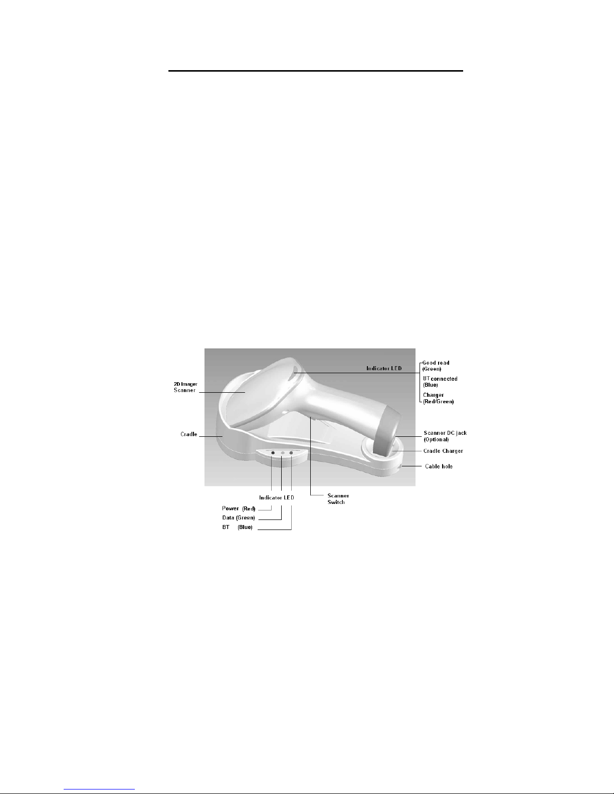
IG300BT is a high performance wireless 2D imager
barcode scanner supporting liner, area imager
barcode scanning.
This device is very easy to configure by this manual,
you can set up by scanning all necessary
programming codes one time that meet applications,
the settings are directly saved permanently, and all
settings can be disabled after scan reset factory
default.
2.2 Illustration
IG-300BT Series
Page 8

8
3. Installation
3.1 Unpacking
1) Take device and its accessories out of the box.
2) Remove the packing material.
3) Check the standard shipment packing list to make
sure you have received all of the items ordered.
Wireless 2D Imager Scanner
Bluetooth Cradle or Charger (optional)
Power Adaptor (if applied)
Communication Cable
Skip resistant pad
Iron panel of cradle and screw
Quick Start Guide
4) Visually inspect the device and accessories for
any evidence of physical damage.
5) If anything is missing or appears to be damaged,
immediately contact your dealer.
ATTEN
T
ION:
Store the packing material and boxes: It should
be used whenever the device is transported for
servicing.
3.2 Mounting
Once you have unpacked all components, you can
start installing the device as below steps:
IG300BT Scanner
1) The Scanner must be charged for a minimum
of 8 hours before the scanner can be placed
in full operation for the first time.
2) The cradle will indicate in red light when the
scanner is being charged.
3) Once the battery is full, green LED of scanner
will be ON. And green light will be OFF when
the scanner leaving from cradle. The battery
will over charged when battery full charged
again, red and green LED will flashing.
4) If the battery power capacity is too low, the
Page 9
9
scanner will indicate with red LED and beeper
warning.
IG300BT Cradle
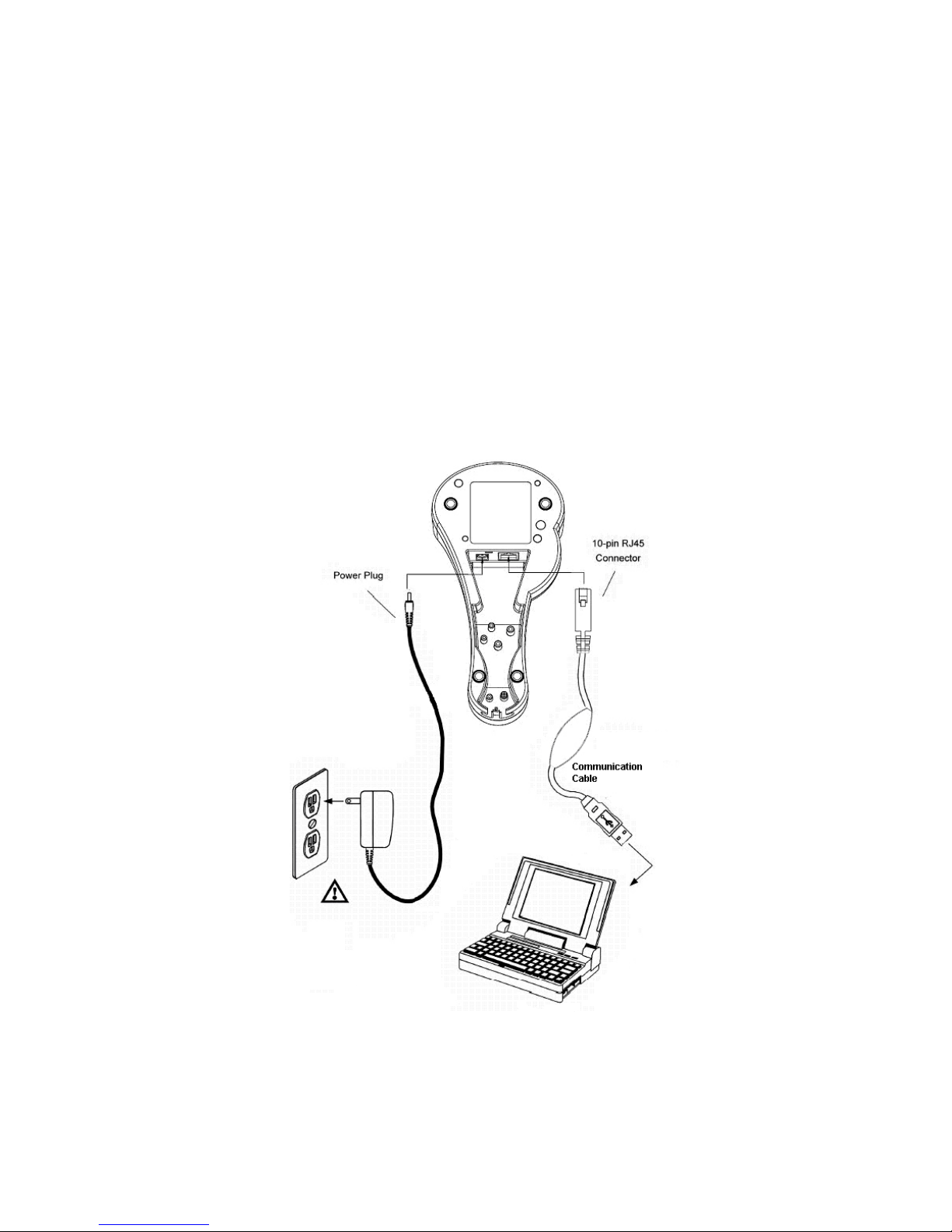
1) Connect the supplied communication cable at
the bottom side of the scanner and you will
hear a “click” when the connection is made.
2) Turn off the host system.
3) Connect the other side of the communication
cable to the right connector of your Host
system.
4) Plug the external power supply into the power
jack on the bottom of the cradle.
5) Plug the power supply into the AC outlet.
6) Turn on your Host system.
7) To set up Bluetooth Communication between
the scanner and cradle. (see chapter 4)
Page 10
10
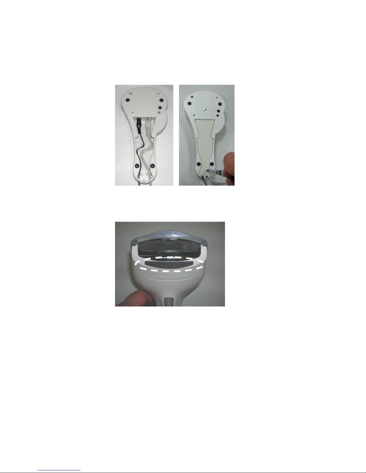
Cable Installation
Connect cable and adaptor to Cradle. The other
end of cable will be connected with Host device.
Lock the iron panel of Cradle by screwdriver.
Skip resistant pad position
Page 11
11
4. Set up Bluetooth
Communication
Before the operation, Bluetooth Communication must
be set up between the scanner and cradle.
4.1 Pairing
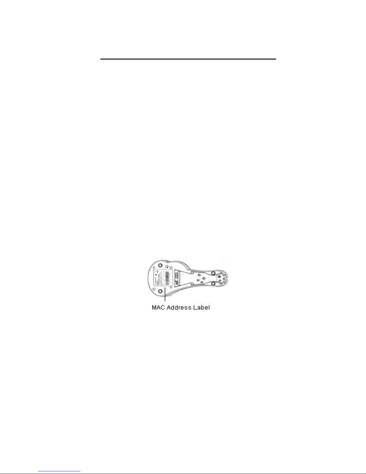
Each scanner has to be linked or paired to a cradle
by scanning the unique Bluetooth MAC address code
located on the bottom of cradle. The pairing between
scanner and cradle is one to one that is one scanner
can be paired to a cradle only.
4.2 Set up Master Mode
Communication
Please follow the steps to set up the communication
between the scanner and cradle.
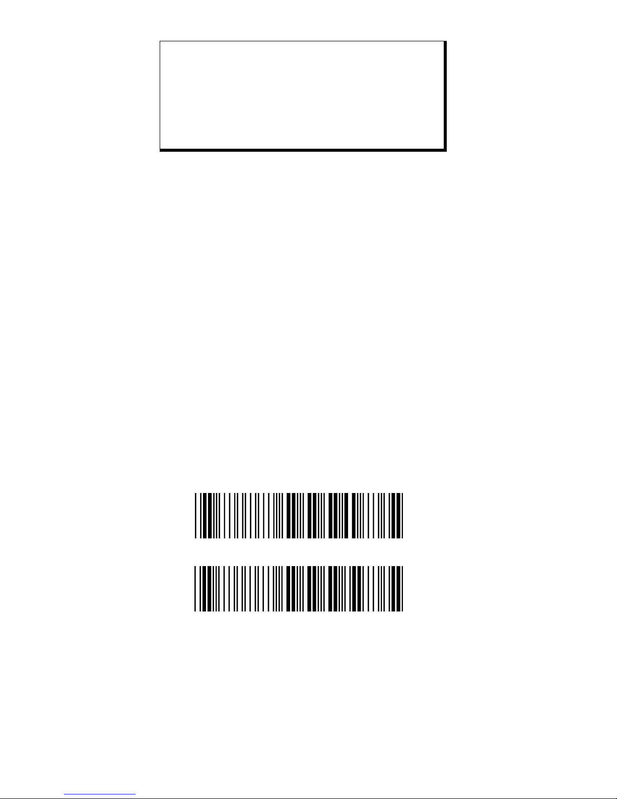
1) The scanner must scan “Scanner Master Mode”
barcode, to set the scanner in Master mode.
2) Scan the Bluetooth MAC address code located on
the bottom of the cradle.
3) When the Bluetooth MAC address code was
successfully scanned, scanner will sound 2 short
beeps with blue and red LED flash once.
4) Wait approximately five seconds, for completing
the connection process with a long beep sound.
5) If successful, Blue LED of scanner will slow flash
and the cradle will be continued on.
6) If the connections failed the scanner indicates
with 3 shot beeps and the cradle with blinking
blue LED.
Page 12
12
ATTENTION:
It is important to know that the scanner will only
communicate with the cradle with the unique Bluetooth
MAC address. Other scanner can not pair with that
cradle until the original connection is broken. If the
cradle pairs with another scanner, the cradle will
disconnect with the first scanner and then re-connect
with another scanner.
4.3 Set up Slave Mode Communication
Please follow the below steps to set up the
communication between the scanner and Bluetooth
application device.
1) The scanner must scan “Scanner Slave Mode”
barcode, to set the scanner in Slave mode.
2) Enter the pin code (default 000000) to setup
comport when control the Bluetooth device to
search the scanner.
3) When the scanner is successful connected,
scanner will sound 1 long beep.
4) If successful, Blue LED of scanner will slow flash.
5) If the connections failed the scanner indicates
with 3 shot beeps.
4.4 Scanner Slave/Master Mode
Scanner Slave Mode
<Scanner Master Mode>
Page 13
13
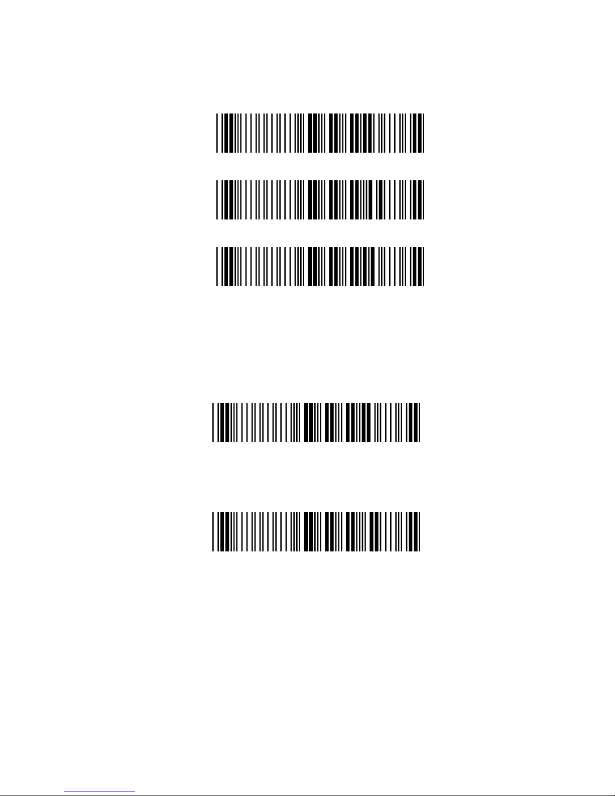
4.4.1 Set Scanner Pin Code Mode
Set Default Security Code
<PINCODE = 000000>
Set Security Code ON
<Set Security code OFF>
4.4.2 Set Pin Code Character
(PINCODE max. 6 digits/0-9and A-Z ASCII CODE)
Set Default Security Code Barcode
<PINCODE = 000000>
1) Begin to Set PINCODE
2) Go to the ASCII Tables in Appendixes; scan 6
labels that represent the PINCODE.
3) Complete to Set PINCODE
Page 14
14
4.5 Bluetooth Cradle Setup
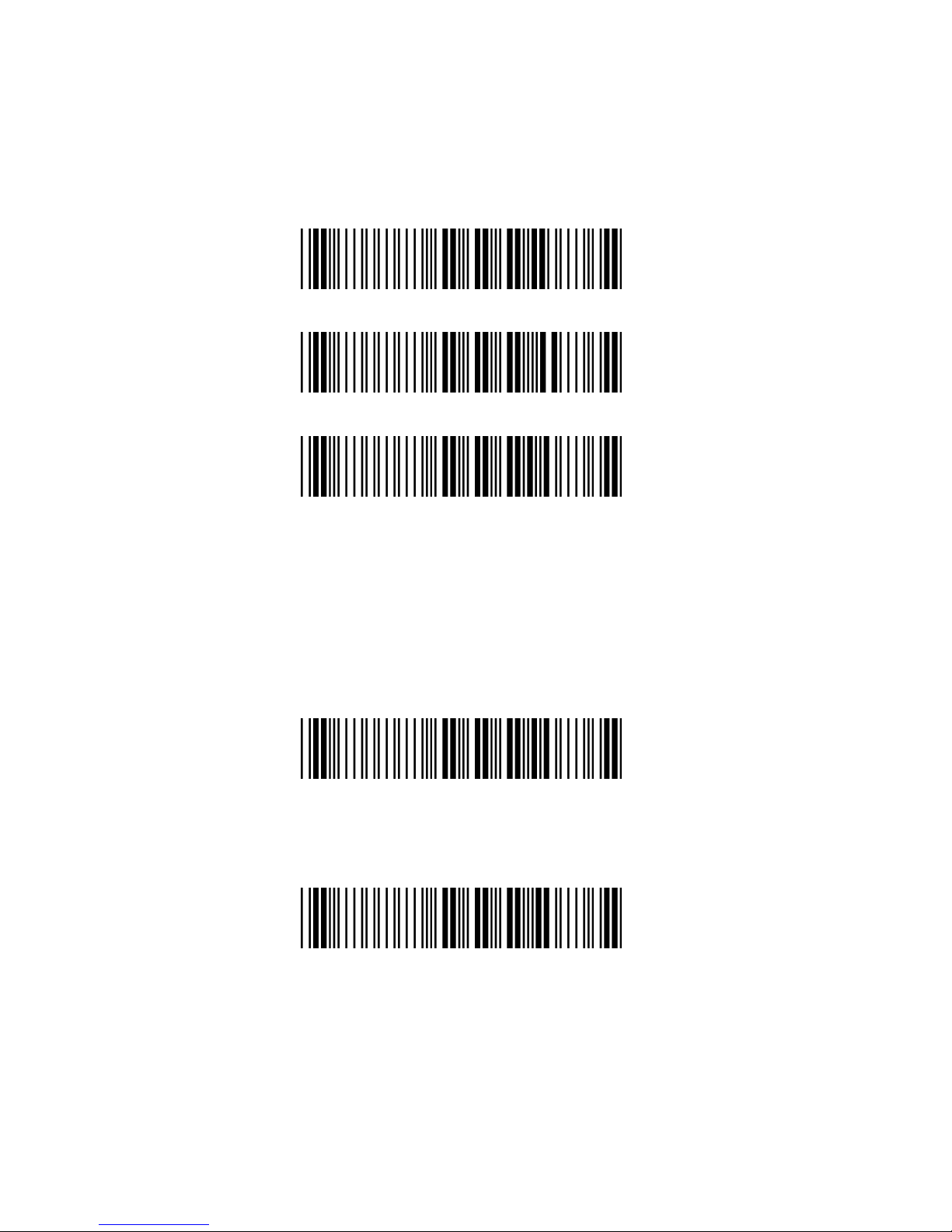
4.5.1 Set Cradle Security Mode
Set Default Security Code Barcode
<PINCODE = 000000>
Set Security ON
<Set Security OFF>
4.5.2 Set Cradle Pin Code
(PINCODE max. 6 digits ,0-9,A-Z ASCII CODE )
Set Default Security Code Barcode
<PINCODE = 000000>
1) Begin to Set PINCODE
2) Go to the ASCII Tables in Appendixes; scan
6 labels that represent the PINCODE.
3) Complete to Set Cradle BT PINCODE
Page 15

15
5. Configuring
5.1 Preface
How to configure this device: The Barcode
Programming Feature gives the possibility to change
the scanner settings with use programming codes.
5.2 Changing Scanner Settings with
Programming Codes
You can setup your device by scanning all necessary
programming codes for parameters that meet
applications. After these scans, the device will save
directly and permanently. To go back to the factory
default settings, just scans the programming code
factory default.
In order to change the scanner settings please follow
the sequence below:
1) Power-up the scanner.
2) Change scanner settings by scanning any of the
programming code that meet applications.
An Example:
For changing the Baud rate to 38400 only scan the
programming code that represents this.
After reading a valid programming code the scanner
will give Di-Du beeps and red-blue LEDs indicator will
flash. And the cradle will give green LED indicator
flash.
At any moment, you can stop your programming and
read programming code factory default to go back to
default.
Page 16

16
5.3 Changing Scanner Settings with
Utility Tool
Manufacturer has setup this scanner with the most
common used programming codes, It could be
possible that you need more advanced settings to
use the scanner without any problems into your
application.
In this case you can setup your scanner by using the
advanced Utility Tool. This tool can be used with the
following operation systems: Windows98,
Windows2000, Windows XP en Windows Vista.
This Utility Tool can be delivered on request. Please
contact your dealer
5.4 Factory Default Settings
The factory default settings are shown with <> and
bold in the followings sections
The readable and default enable symbologies list,
please see Appendixes C.
Page 17
17
6. Operating Settings
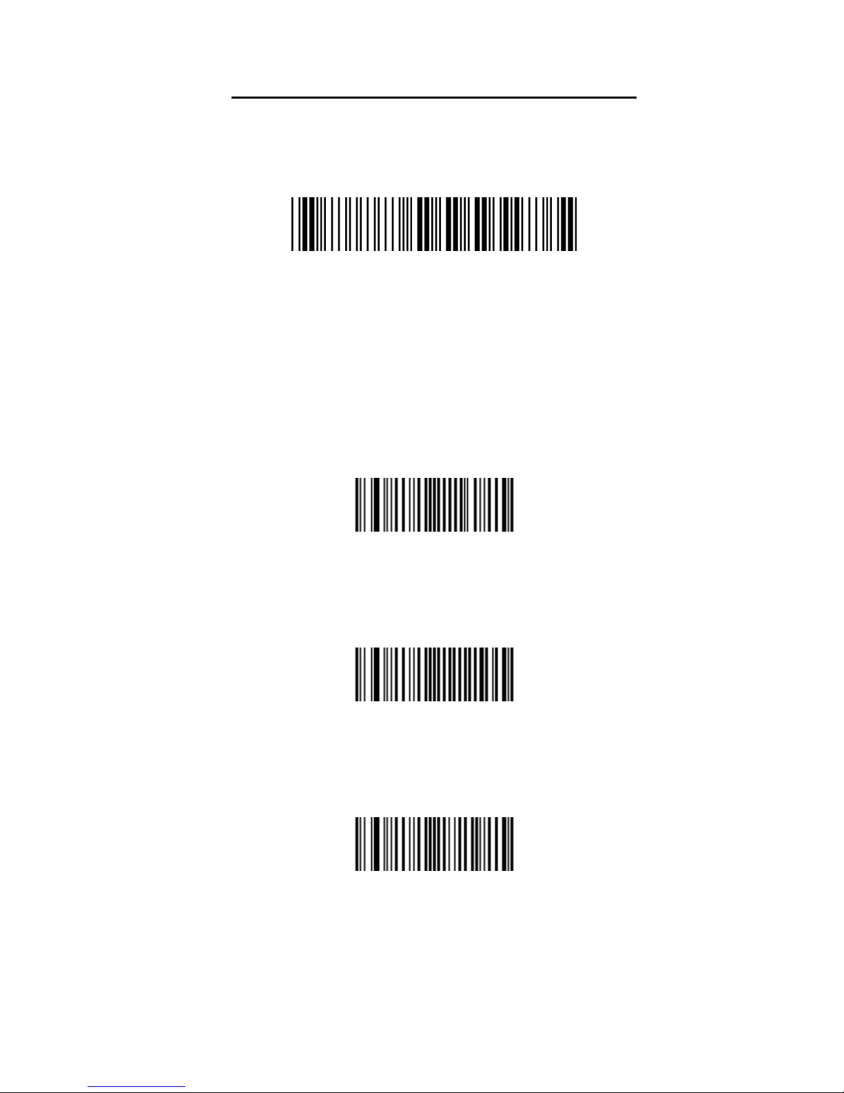
6.1 Factory Default
Set Scanner /Cradle factory default
The scanner and cradle factory default settings are
shown with bold < > in the following pages.
Reset all configuration parameters to their factory
default setting. After this reset you must select all
required parameters that meet applications.
6.2 Scanning Triggering
<Level>
A reading session begins (lighting and decode
processing on) when beam is activated and stops
when beam is deactivated.
Continuous Scanning
When the scanner is turned on a continuous reading
session begins (lighting and decode processing on).
Pulse
A reading session begins when beam is activated
and stays on until a period of inactivity lasting the
time specified by the timeout.
After the timeout, the scan engine turns off.
Page 18

18
Flashing
Flashing mode allows power up the lighting and
decoding are on (no need to activate the trigger line)
and after a period of inactivity lasting the time
specified by the trigger timeout, the scanner starts
flashing, checking for a bar code to be read.
When a bar code is detected, the lighting and
decoding automatically turn on and stay on until
another period of inactivity (timeout), after the timeout
the scanner starts flashing again.
Autostand
This mode allows you to switch from Flashing trigger
mode to Level trigger mode.
Autostand begins in flashing mode: At power up the
lighting and decoding are on (no need to activate the
trigger line) and after a period of inactivity lasting the
time specified by the trigger timeout, the scanner
starts flashing.
To switch to Level trigger mode activate the trigger
line (press the trigger).
When in Level trigger mode, after a period of
inactivity lasting the time specified by the trigger
timeout, the scanner switches back to flashing mode.
Toggle
This mode allows lighting and decoding toggle when
the trigger line is activated.
First trigger activation = lighting and decoding on,
second trigger activation = lighting and decoding off.
Page 19

19
Presentation
This mode allows power up lighting and decoding are
on. After a period of inactivity lasting the time
specified by the trigger timeout, the lighting turns off
or is dimmed. When a new bar code is presented the
lighting and decoding restart and stay on until
another period inactivity.
6.3 Trigger Time Out
<2 sec>
4 sec
6 sec
Page 20

20
6.4 Good Read Mode
When active, the scan engine stops the reading
session after a successful decoding.
Note: This parameter is NOT used with continuous
and continuous + flashing modes.
<Active >
Not Active
6.5 Buzzer Beep Tone
6.5.1 Beep Tone Setup
<High >
Medium
Low
Page 21
21
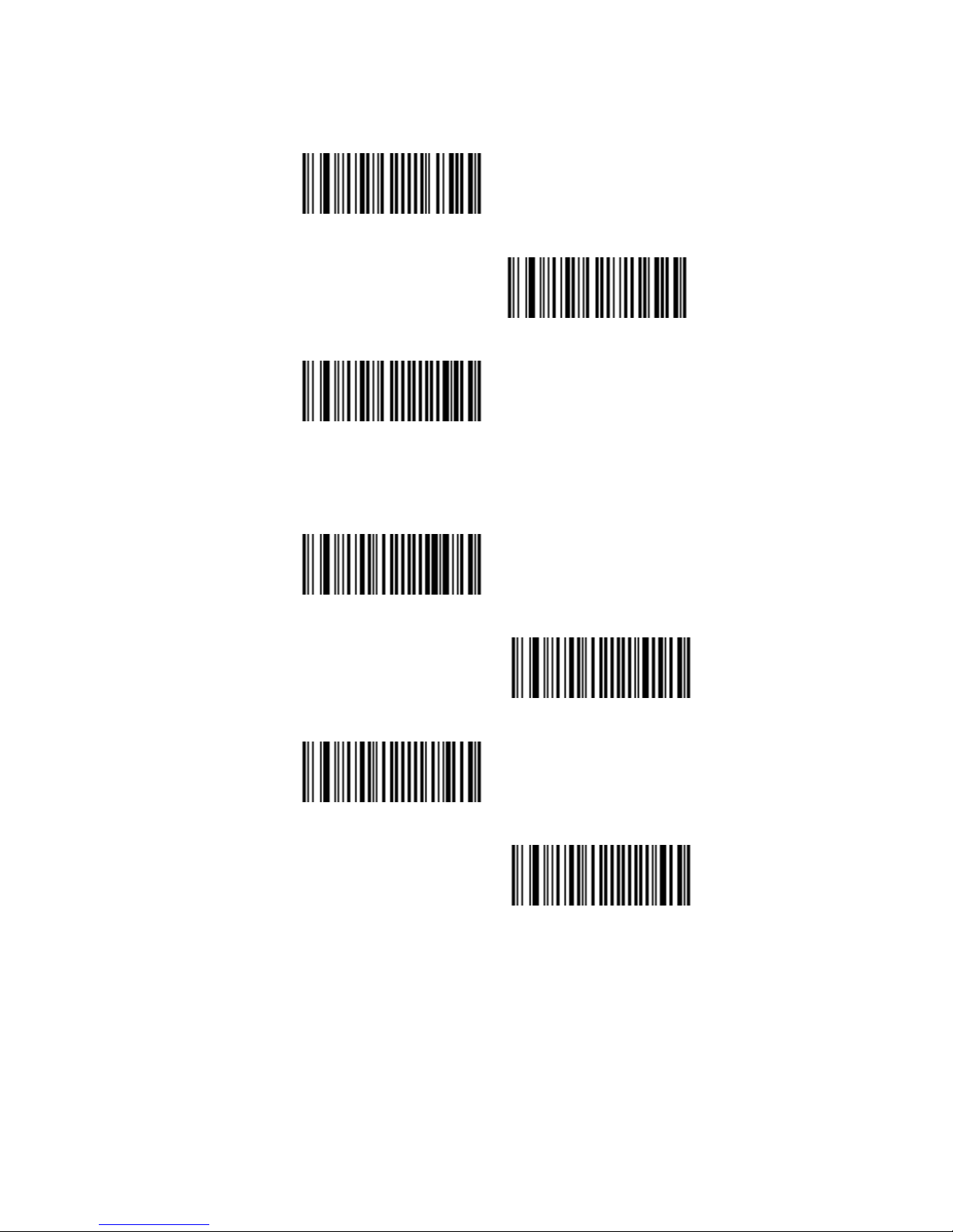
6.5.2 Good Read Beeps
<One Beep >
Two Beeps
None
6.5.3 Beep Duration
60 msec
<80 msec>
200 msec
Off
Page 22
22
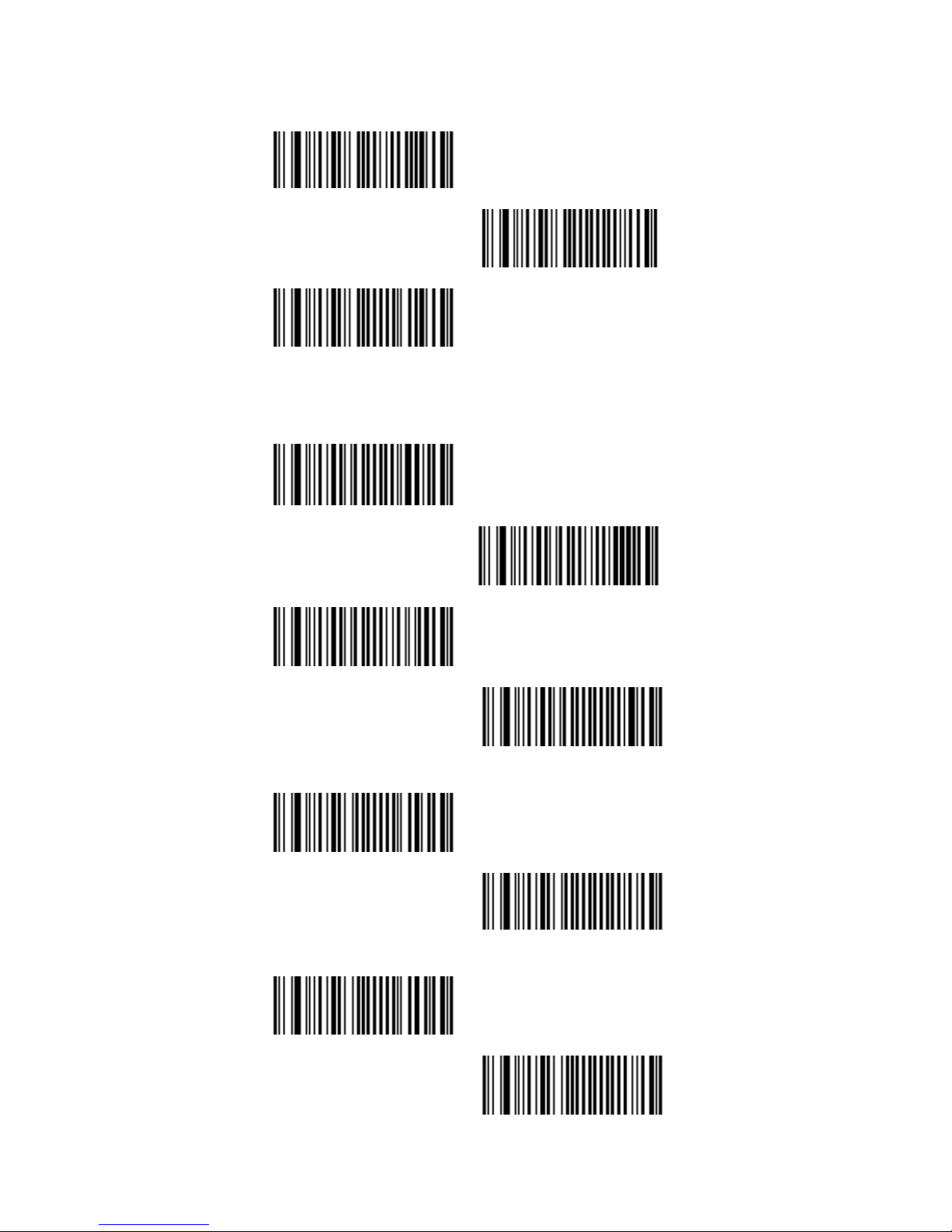
6.5.4 Timing
<During Transmission>
Before Transmission
After Transmission
6.5.5 Good Read Duration
<80 msec>
0.5 sec
1 sec
Off
6.5.6 Error Beep
<On>
Off
6.5.7 Setup Beep
<On>
Off
Page 23

23
7. Imager Settings
7.1 Imager Mode
You can set the best reading performance depends
on the environment, your used application and type
of barcodes.
Linear mode for decode 1D Barcodes.
Area mode for decode 1D and 2D barcodes.
Area mode allows you to set the position of the
VEGA in any direction regardless of the orientation of
the barcode, and perform a good read on 1D and 2D
barcodes.
Linear mode allows you to increase your decoding
speed while scanning 1D barcodes. But, you need to
position the beam across all bars in the 1D barcode.
<Area imager>
Linear imager
Area imager
Bright Environment
Area imager
Reflective Surface
Page 24
24
7.2 Sleep Mode
The scanner is equipped with sleep mode function
to save battery energy when the scanner is not used
for 1 minute or 10 minute. During sleep mode, all the
functions and connection will be halted until pressing
the trigger button of scanner to wake up and
reconnect the communication with the cradle or
Bluetooth device.
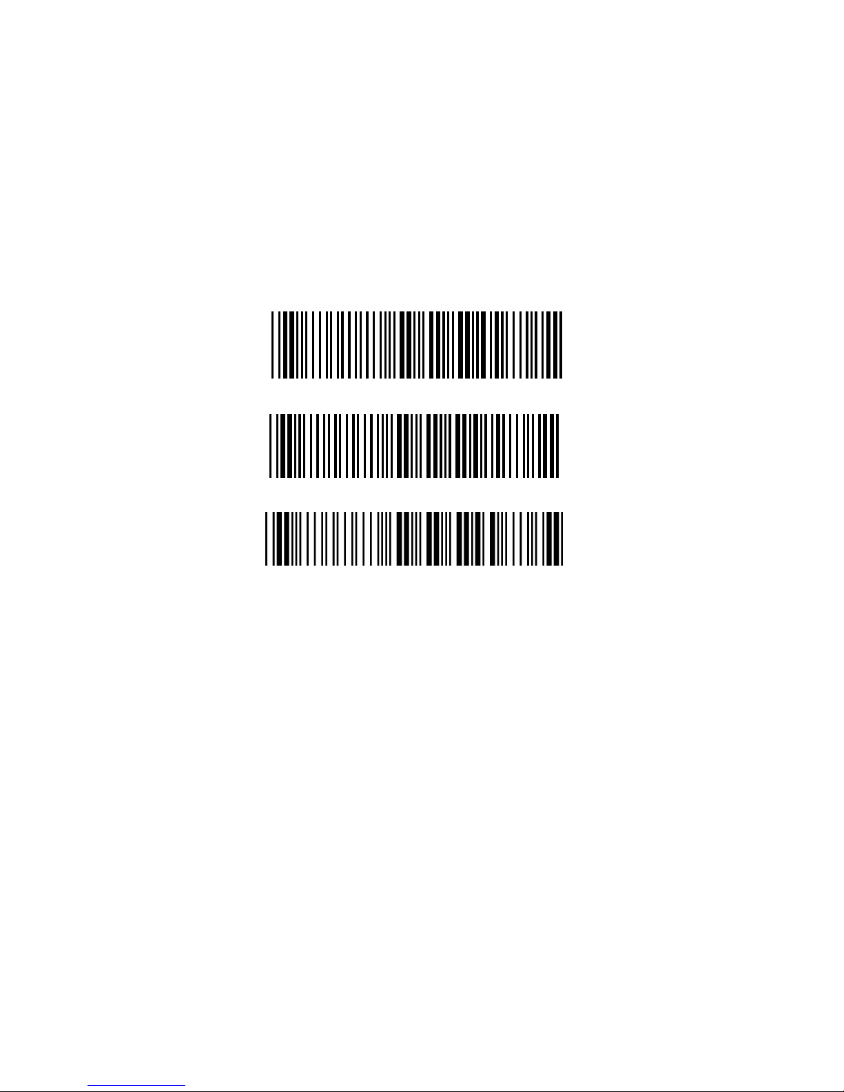
<Sleep Mode 1 min. ON>
Sleep Mode 10 min. ON
Sleep Mode OFF
Page 25

25
7.3 Batch Mode
This Batch mode function is enabled when you have
scanned “Memory ON” barcode. Scanning data is
stored in the memory of the scanner. This function is
disabled when you have scanned “Memory OFF”
barcode.
When you have scanned “Out Of Range” barcode,
The scanner transmits the scanning data of work
range. In case of the scanner is out of working range,
the scanner will store the scanning data to memory.
You can scan the barcode “Memory read” barcode to
transmit the stored data to cradle immediately of
working range.
When the communication reconnected again, you
can scan the barcode “Memory read” barcode to
transmit the stored data to cradle immediately. Or
scan the “Memory clear” barcode to erase all stored
memory. The capacity of this memory depends on
the scanned data size, approximately 20,000 sets for
EAN13 of data .
Out Of Range
Memory Mode ON
<Memory Mode OFF>
Memory Read
Memory Clear
Page 26
26
7.4 Firmware Version
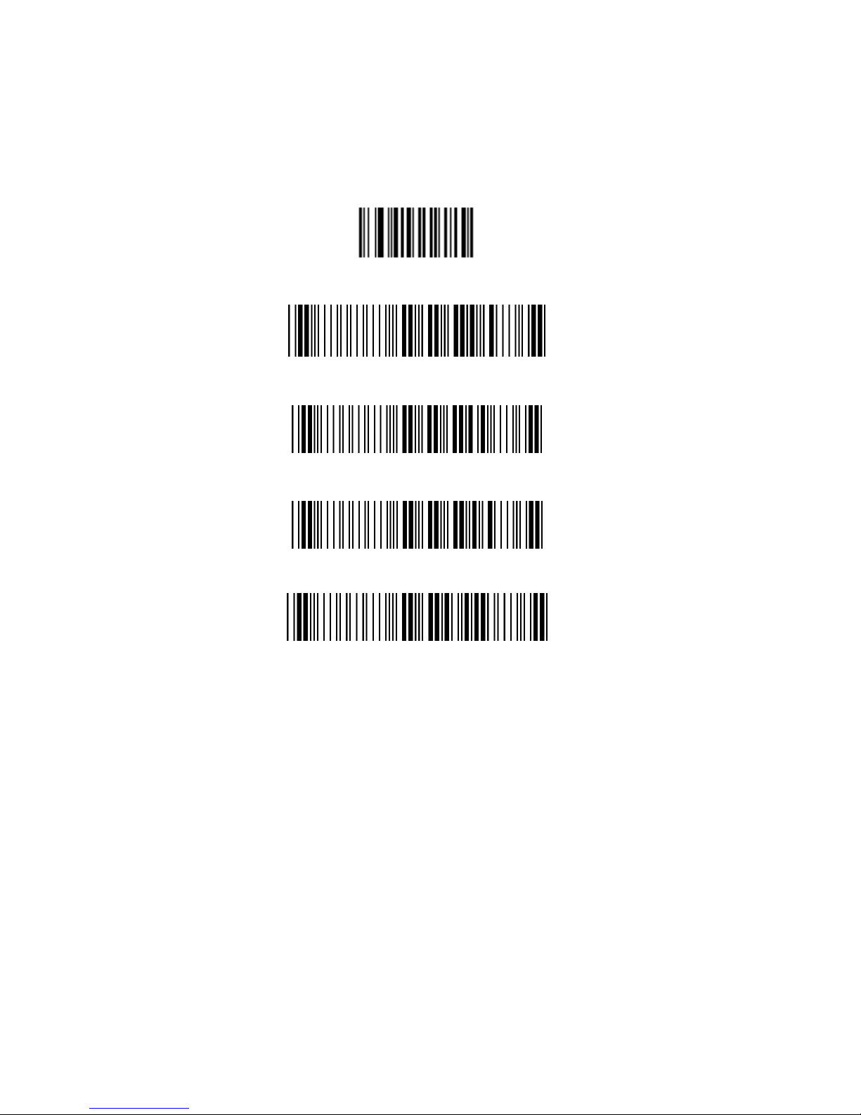
Display the firmware version of the scanner, please
scan below barcode.
7.4.1 Engine Firmware Version
7.4.2 Scanner Decoder Firmware Version
7.4.3 Cradle Decoder Firmware Version
7.4.4 Scanner Bluetooth MAC Address
7.4.5 Cradle Bluetooth MAC Address
Page 27
27
7.5 Set Cradle Interface Barcode
Set Cradle KB Interface Barcode
Set Cradle RS232 Interface Barcode
<Set Cradle USB HID Interface Barcode>
7.6 Cradle RS232 Communication
Parameter
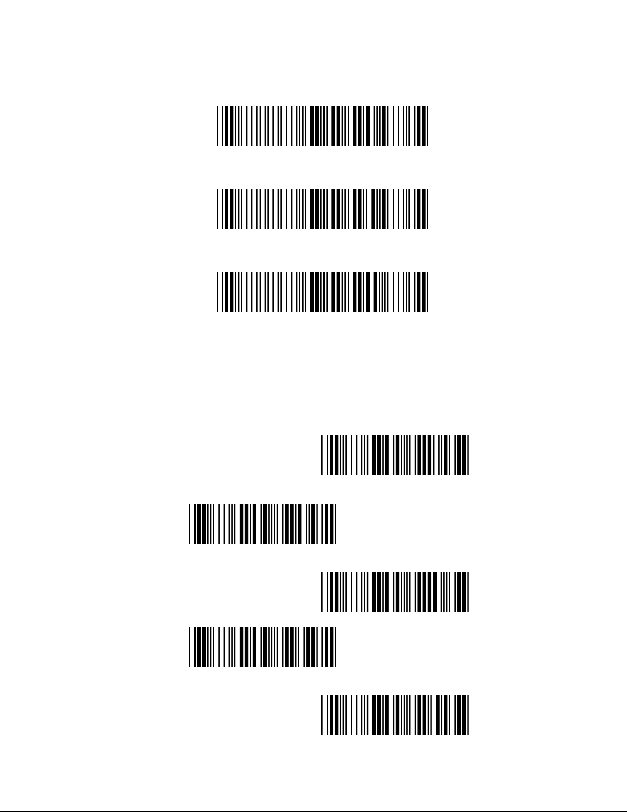
7.6.1 Cradle Baud Rate
1200
2400
4800
9600
<19200>
Page 28
28
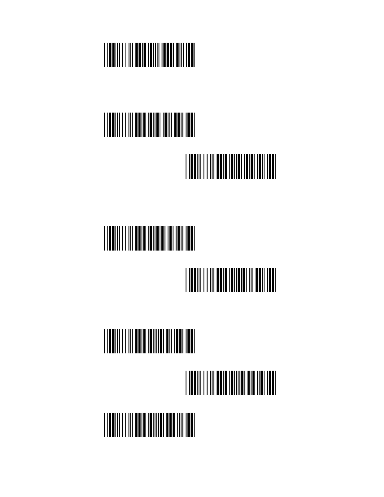
38400
7.6.2 Cradle Data Bits
7 data bits
<8 data bits>
7.6.3 Cradle Stop bits
<1 bit>
2 bits
7.6.4 Cradle Parity
<None>
Even
Odd
Page 29
29
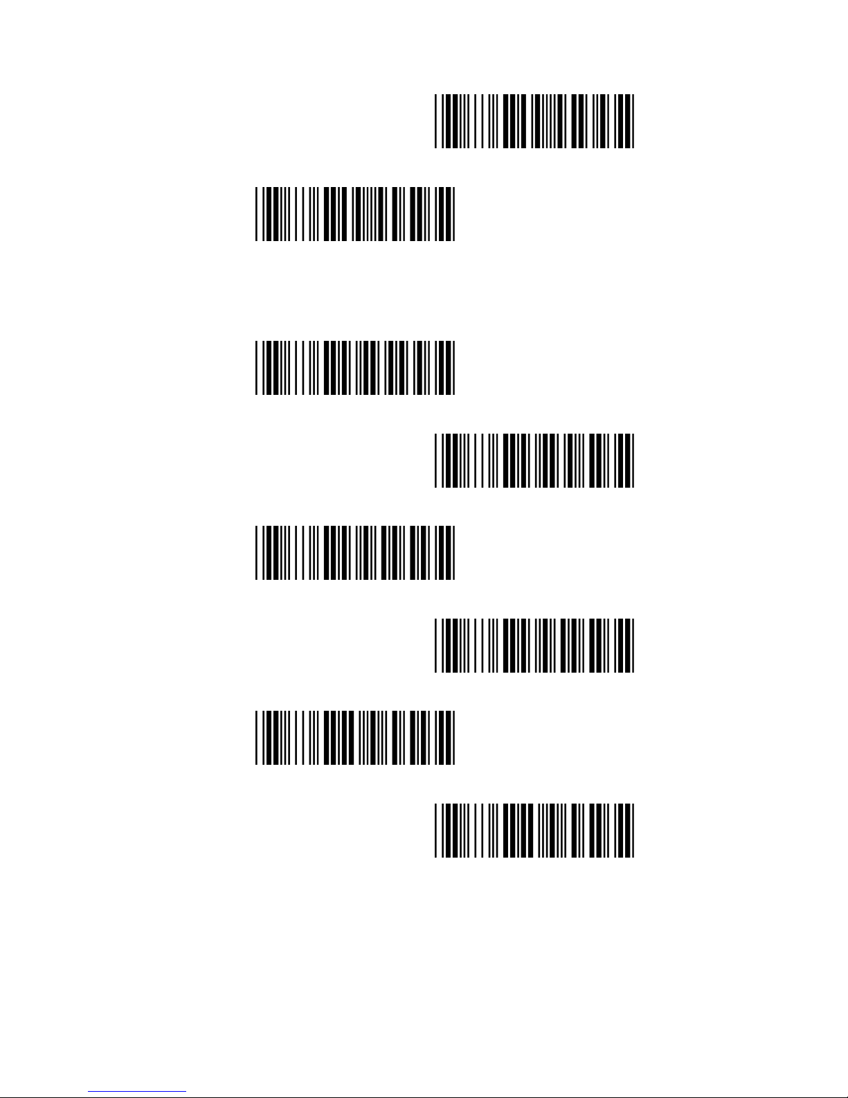
Mark
Space
7.6.5 Cradle Hand Shaking
RTS/CTS Enable
<RTS/CTS Disable>
ACK/NAK Enable
<ACK/NAK Disable>
XON/XOFF Enable
< XON/XOFF Disable >
Page 30
30
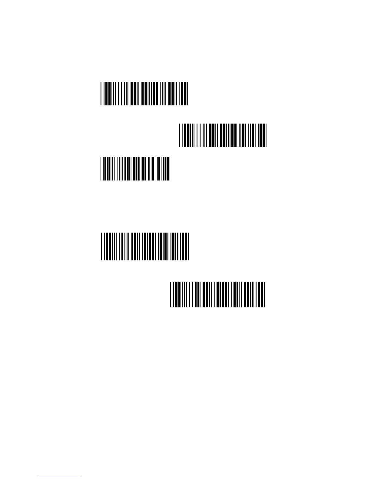
7.6.6 Cradle Keyboard Wedge Mode Parameters
1) Terminal type
<IBM PC/AT,PS/2>
IBM PC/XT
IBM PS/2 25, 30
2) Capslock Detection
Enable
<Disable>
Page 31
31
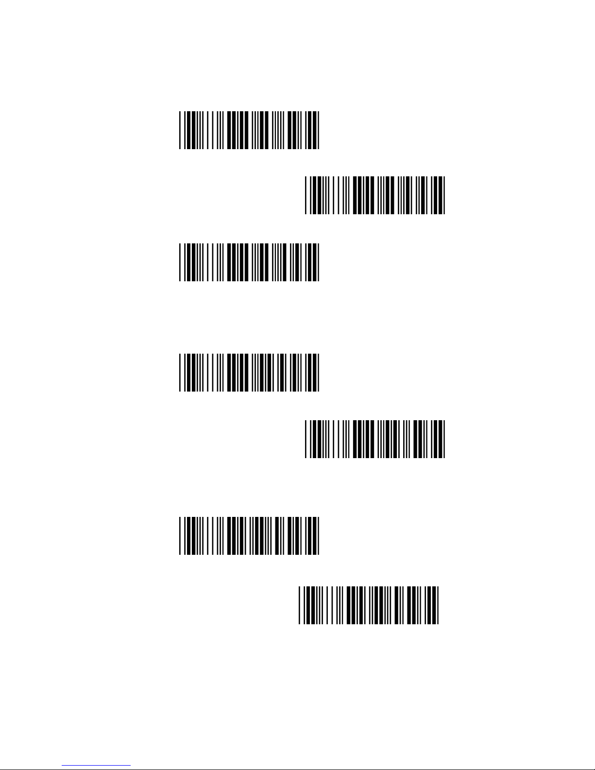
3) Upper/Lower Case
<No change>
Upper Case
Lower Case
3) Send Character by ALT Method
Enable
<Disable>
4) Select Numerical Pad
ON
<OFF>
Page 32
32
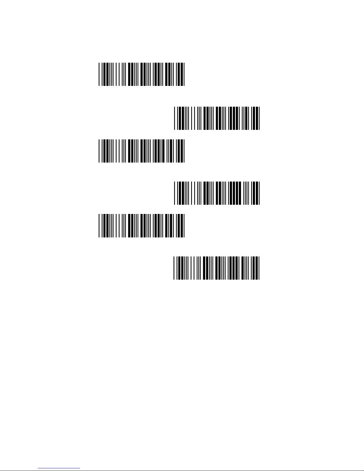
5) Time out Between Characters
<0 ms>
5 ms
10 ms
25 ms
50ms
100ms
Page 33
33
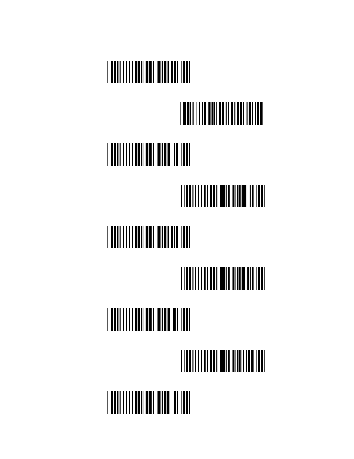
6) Language Selection
<US English>
UK English
Italian
Spanish
French
German
Swedish
Switzerland
Hungarian
Page 34
34
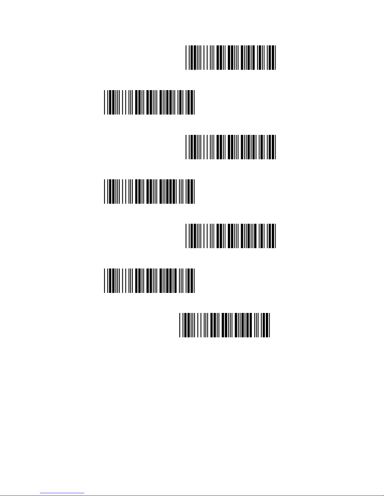
Japanese
Belgium
Portuguese
Denmark
Netherlands
Turkey
Reserved 1
Page 35
35
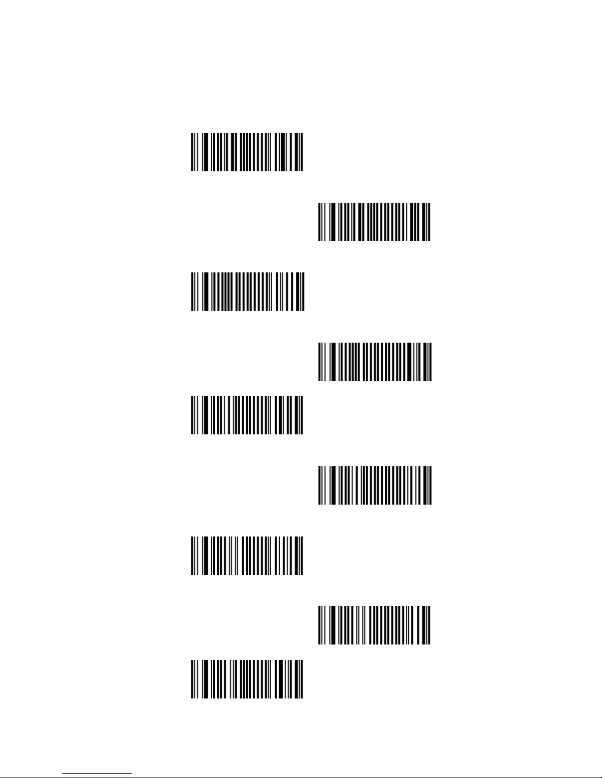
7.7 Decoding Selection
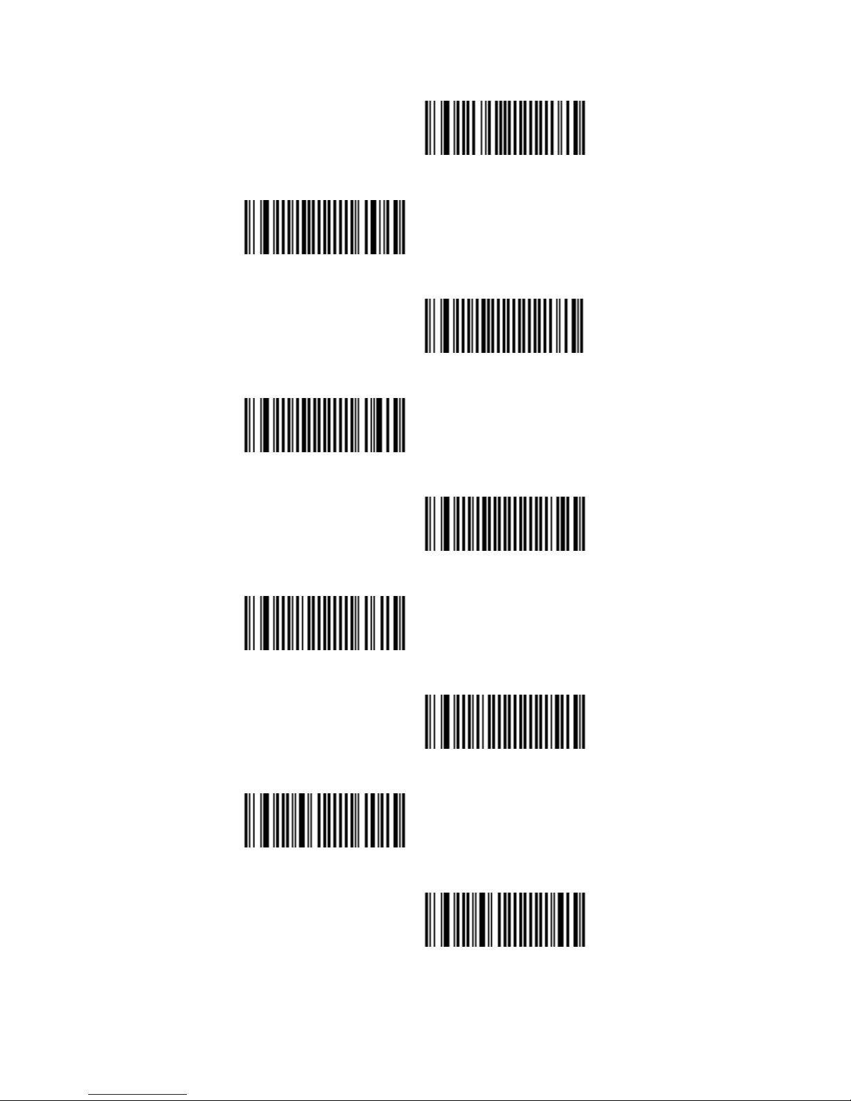
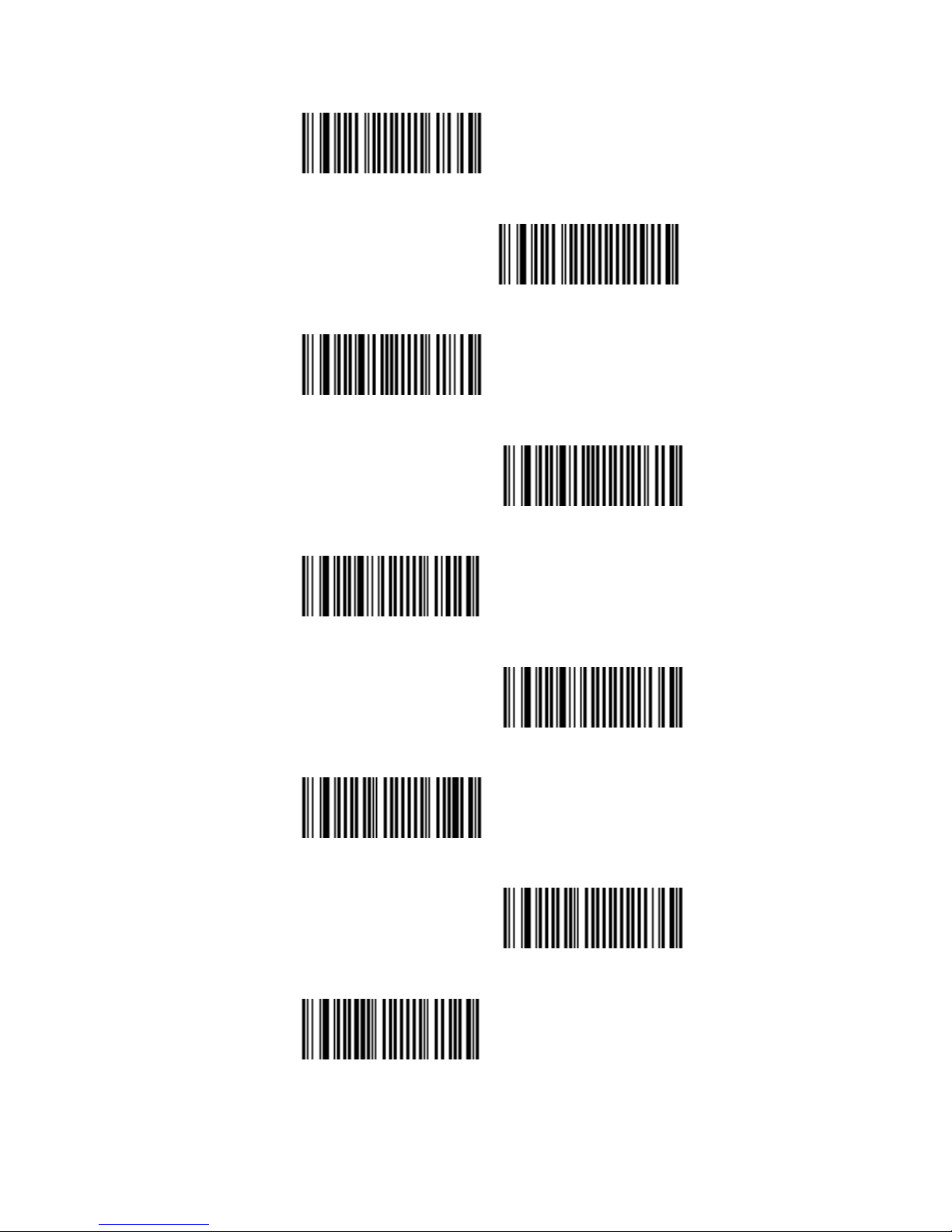
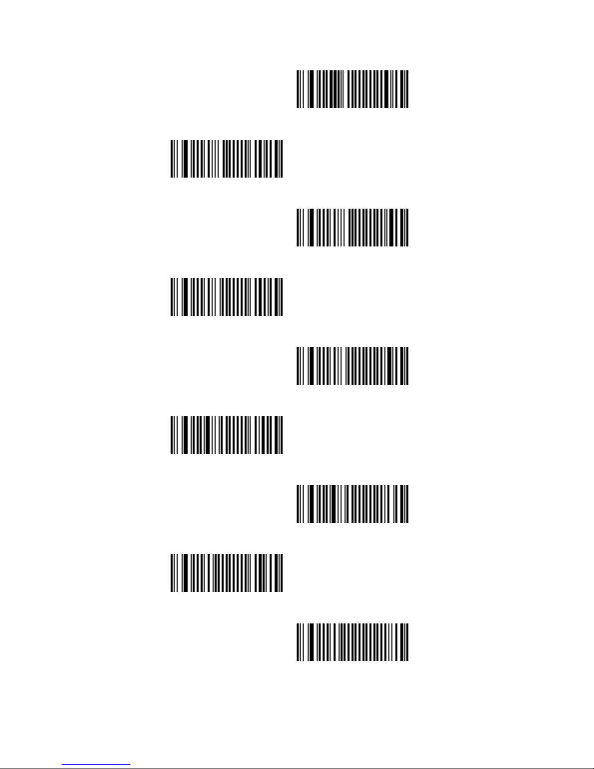
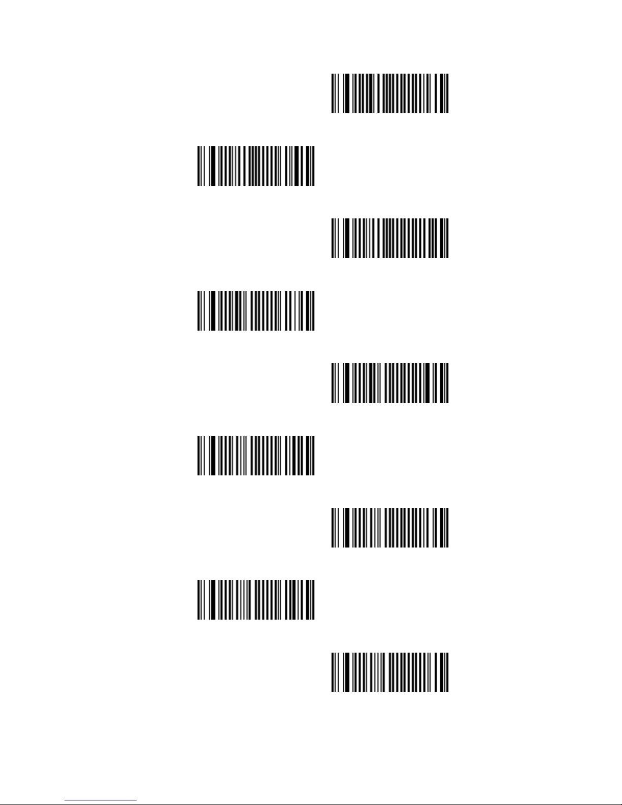
7.7.1 Symbologies Selection
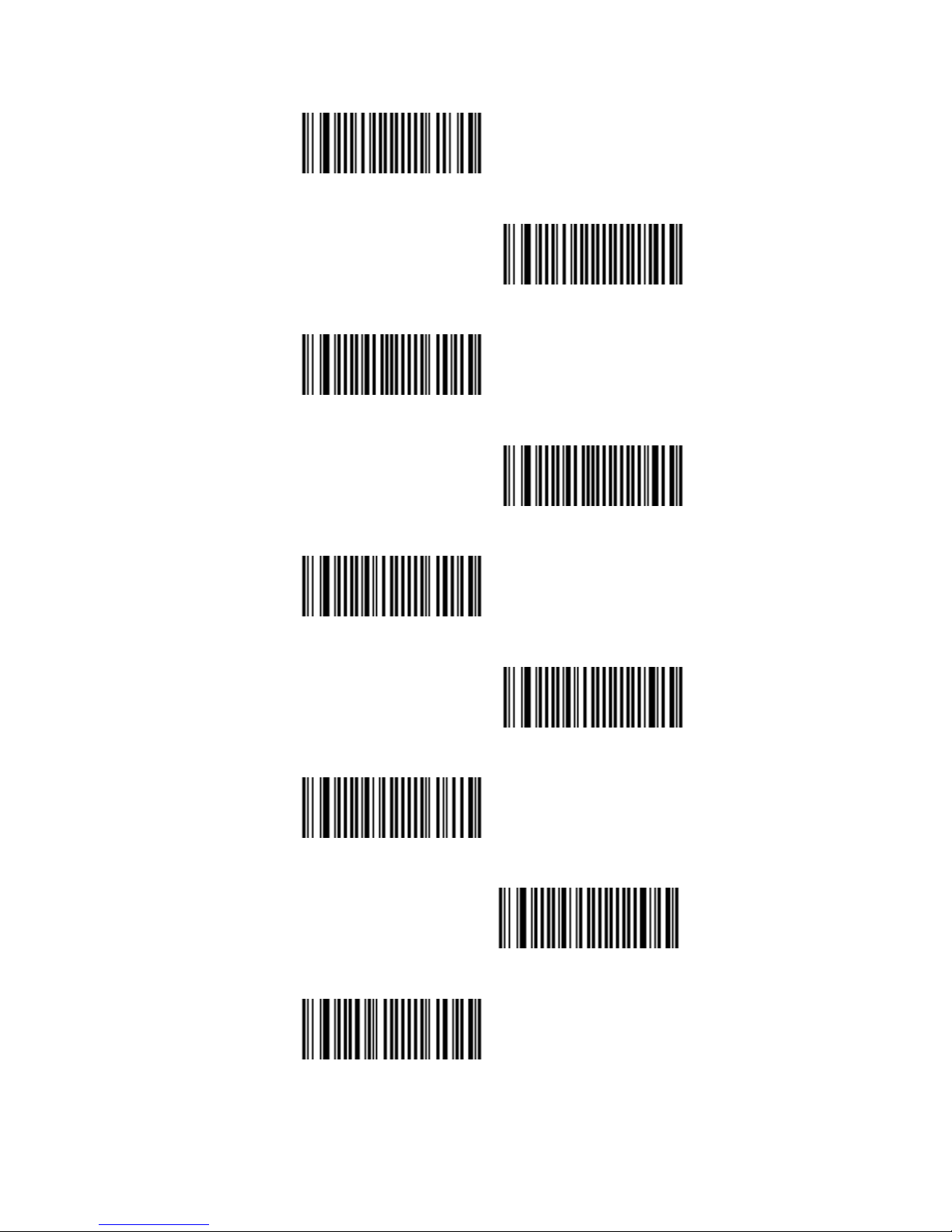
Australian Post ON
<Australian Post OFF>
AZTEC ON
<AZTEC OFF>
BPO ON
<BPO OFF>
Canada Post ON
<Canada Post OFF >
CODABAR ON
Page 36
36
<CODABAR OFF>
Codablock A ON
<Codablock A OFF >
Codablock F ON
<Codablock F OFF >
CODE 11 ON
<CODE 11 OFF>
<CODE 39 ON>
CODE 39 OFF
Page 37
37
CODE 93 ON
<CODE 93 OFF>
<CODE 128 ON>
CODE 128 OFF
<GS1-128 ON>
GS1-128 OFF
<DATAMATRIX ON>
DATAMATRIX OFF
Dutch Post ON
Page 38
38
<Dutch Post OFF>
<EAN-8 ON>
EAN-8 OFF
<EAN-13 ON>
EAN-13 OFF
<EAN 128 ON>
EAN 128 OFF
GS1 CC-A/B ON
<GS1 CC-A/B OFF>
Page 39
39
GS1 CC-C ON
<GS1 CC-C OFF>
GS1 DataBar-Omni ON
<GS1 DataBar Omni OFF >
GS1 DataBar Limited ON
<GS1 DataBar Limited OFF>
GS1 DataBar Expanded ON
<GS1 DataBar Expanded>
Infomail ON
Page 40
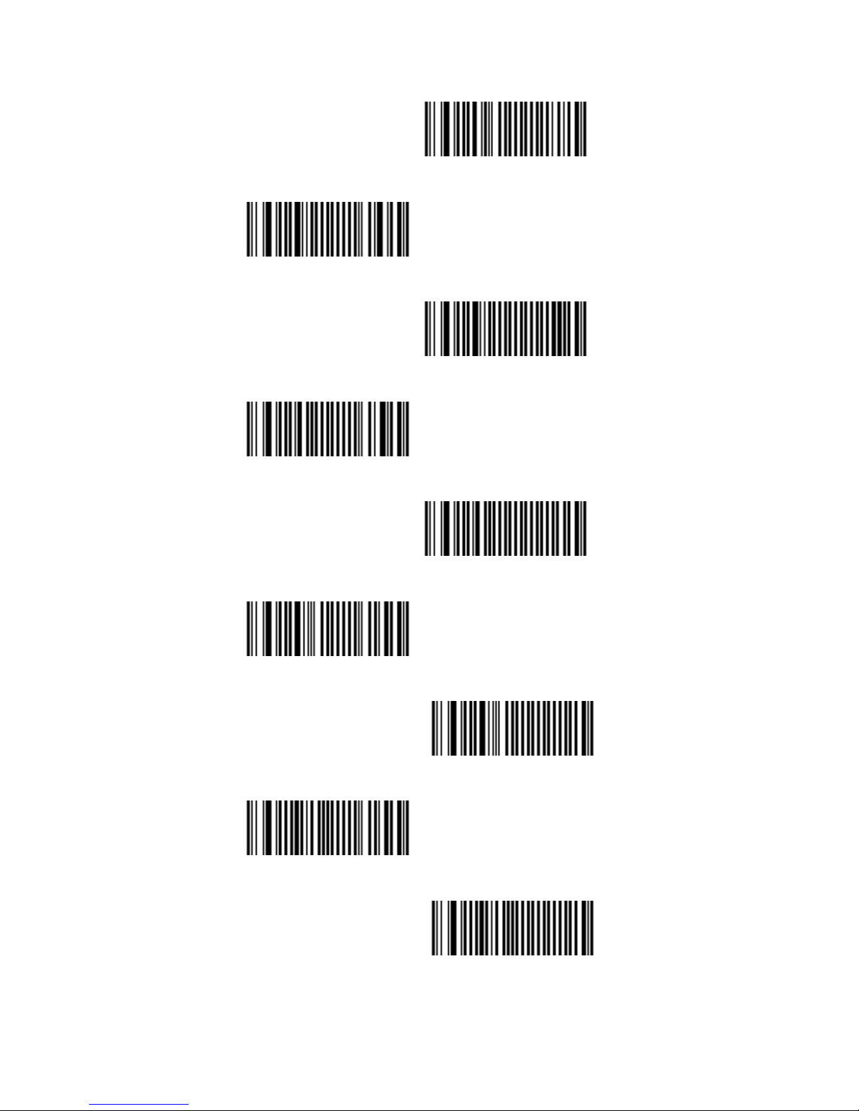
40
<Infomail OFF>
Interleaved 2 of 5 ON
<Interleaved 2 of 5 OFF>
Japan Post ON
<Japan Post OFF>
Matrix 2 of 5 ON
<Matrix 2 of 5 OFF >
MaxiCode ON
<MaxiCode OFF>
Page 41
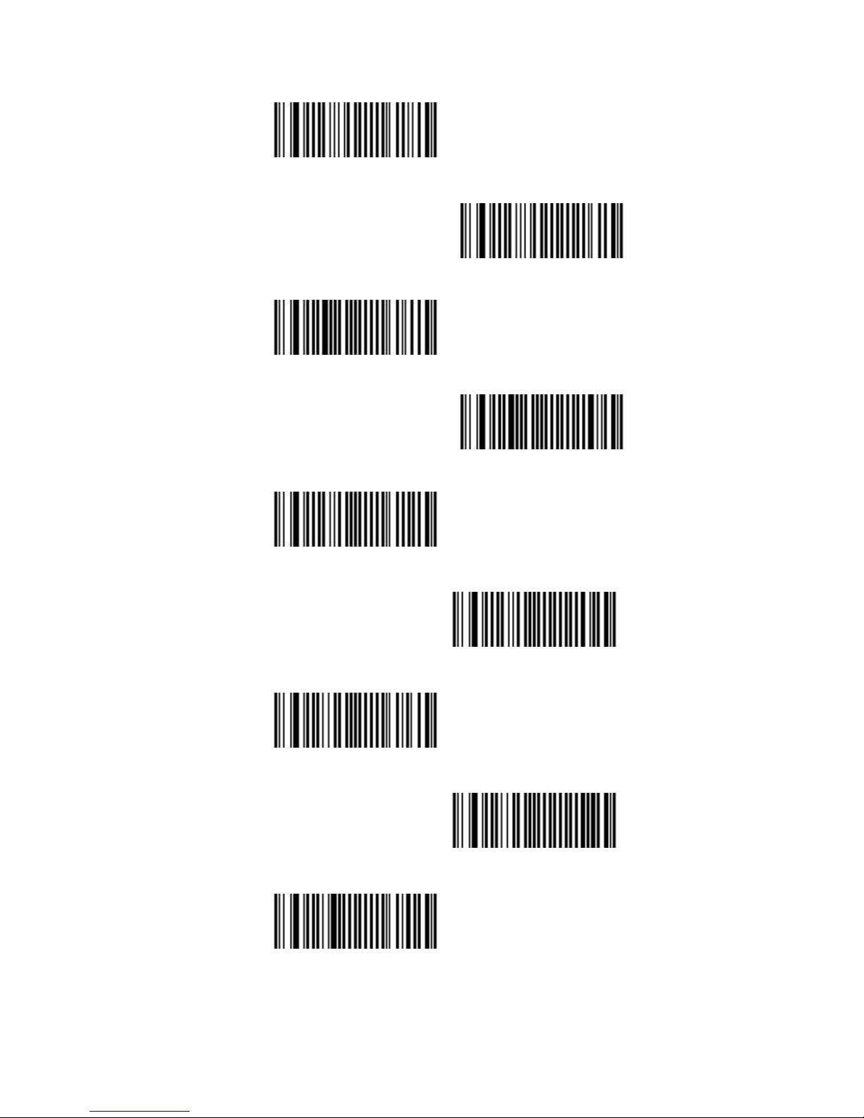
41
MicroPDF417 ON
<MicroPDF417 OFF>
MSI ON
<MSI OFF>
<PDF417 ON>
PDF417 OFF
Planet ON
<Planet OFF>
PLESSEY ON
Page 42
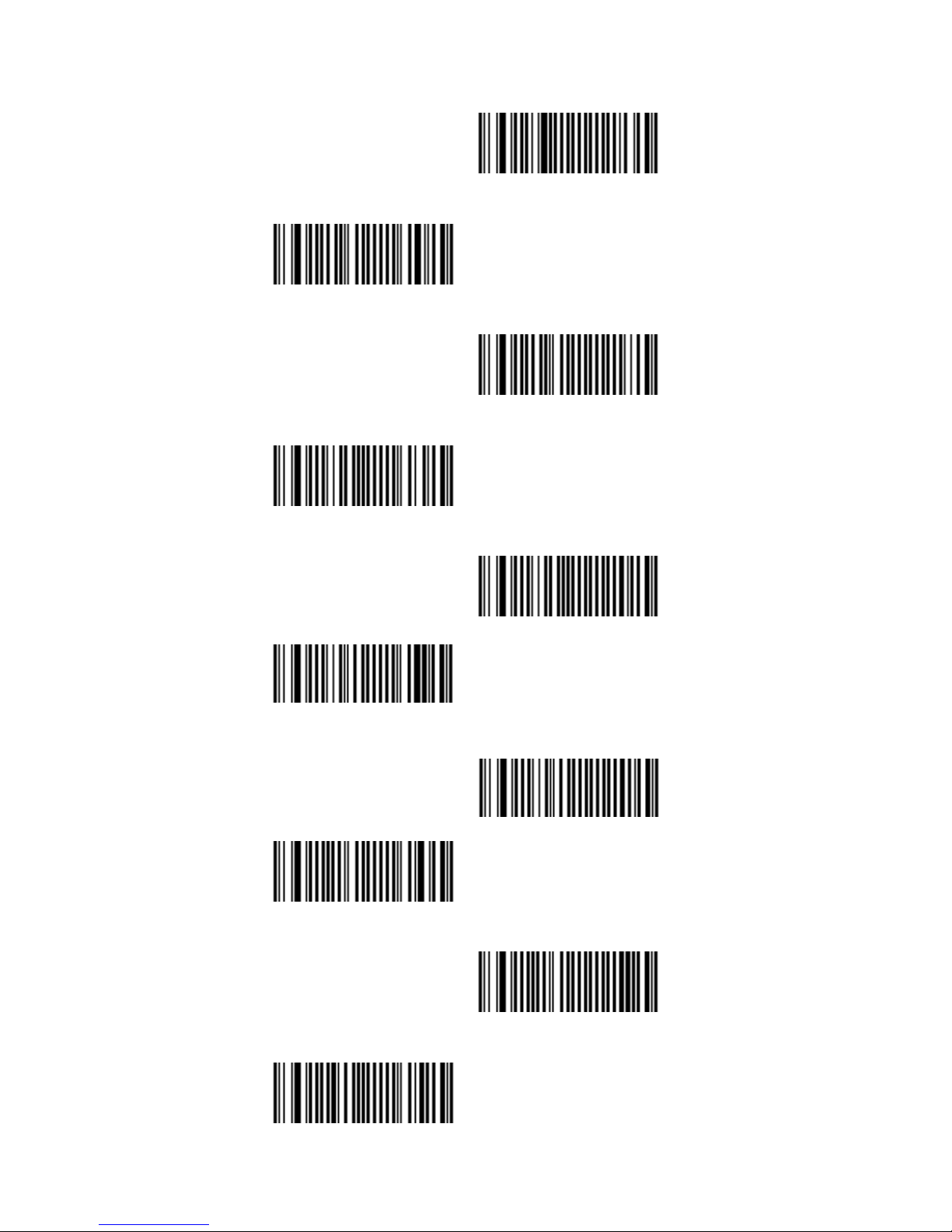
42
<PLESSEY OFF>
Postnet ON
<Postnet OFF>
QR Code ON
<QR Code OFF>
QR Code - model 1 ON
<QR Code - model 1
OFF>
Standard 2 of 5 ON
<Standard 2 of 5 OFF>
Sweden Post ON
Page 43
43
<Sweden Post OFF >
Telepen ON
<Telepen OFF>
TLC 39 ON
<TLC 39 OFF>
<UPC-A ON>
UPC-A OFF
<UPC-E ON>
UPC-E OFF
Page 44

44
7.7.2 Disable All Symbologies.
If you want to disable all Symbologies, please
scan below programming code. Or you can scan
the “Off” option to disable individual symbologies.
Disable All Symbologies
Note: Do not reset individual parameters settings for
each symbology. When you enable a symbology,
you will recover the parameter settings stored in
memory.
Anytime, you may reset to factory defaults by
scanning the programming code of “Set factory
default” (please see 7.1.1)
Page 45
45
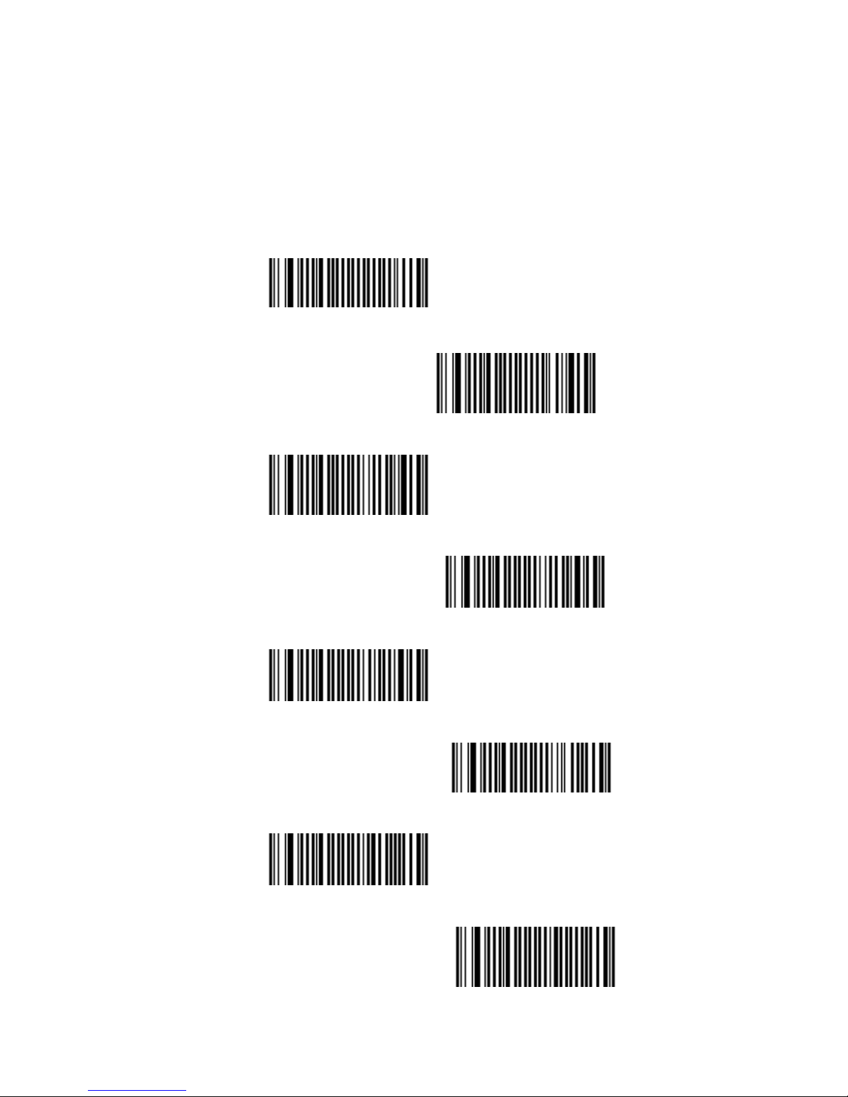
7.7.3 Multi Code
The multicode function is used configure the scanner
to read a series of bar codes and then transmit them
all at once.
<Not Active>
Active
Active Exclusive
Number of bar codes – compose: 2
Number of bar codes – compose: 3
Number of bar codes - compose: 4
Number of bar codes –compose: 5
Number of bar codes – compose: 6
Page 46
46
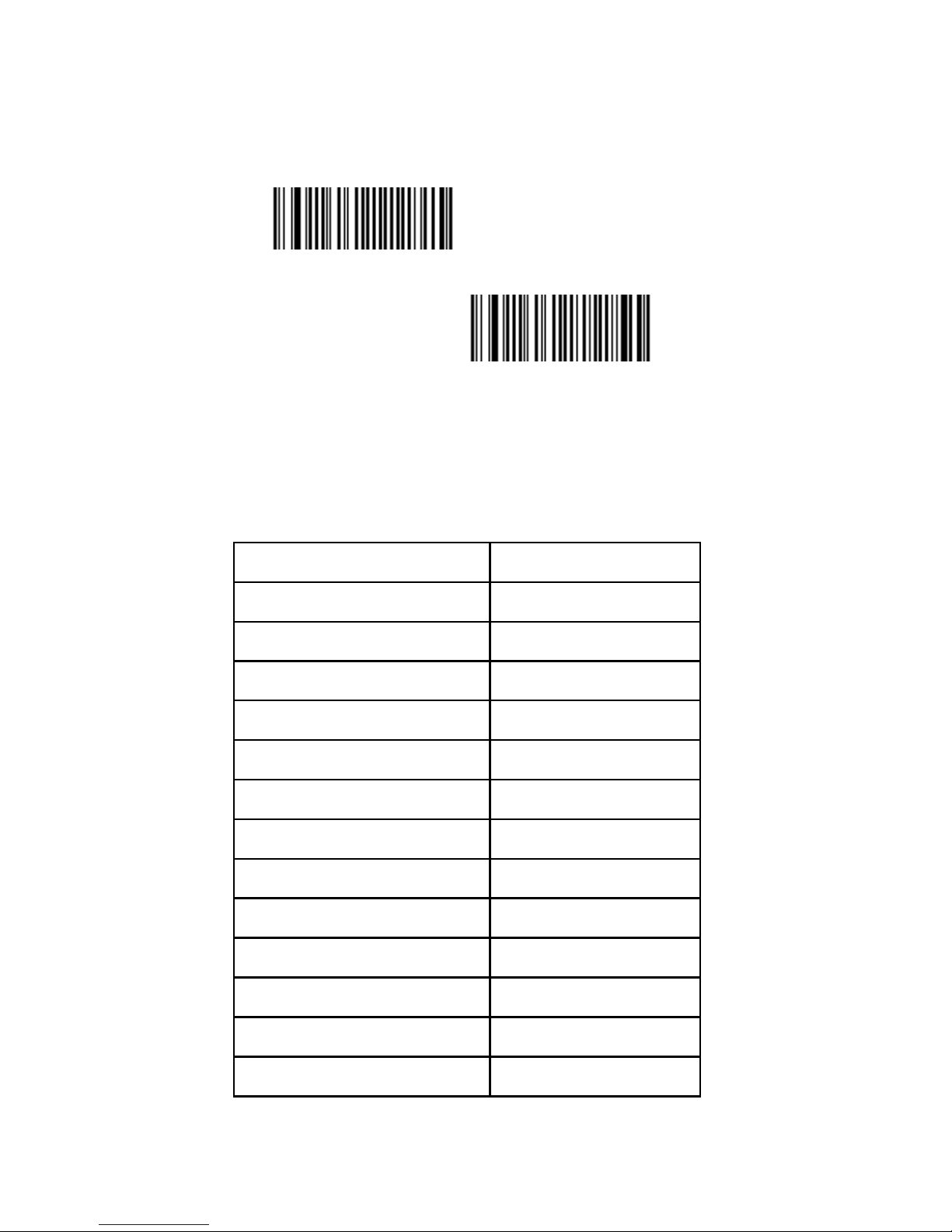
7.7.4 Activates user defined symbology identifier
(UDSI) transmission for all symbologies.
<Not Transmitted >
UDSI Transmitted
Data Format: [UDSI symbology id] <data>
Symbology Default Identifier
Australia Post P3
Aztec D3
BPO P2
Canada Post P6
Codabar B7
Codablock A K0
Codablock F K1
Code 11 C1
Code 39 B1
Code 93/93i B6
Code 128 B3
DataMatrix D0
Dutch Post P4
Page 47

47
EAN-8 FF
EAN-13 F
GS1-128 C9
GS1 Composite A/B G0
GS1 Composite C G1
GS1 DataBar C3
GS1 DataBar Limited C4
GS1 DataBar Expanded C5
Interleaved 2 of 5 B2
Japan Post P5
Matrix 2 of 5 B4
MaxiCode D2
MicroPDF417 C8
MSI Code B8
PDF417 C7
Planet P1
Plessey Code C2
Postnet P0
QR Code D1
Standard 2 of 5 B5
Sweden Post P7
Telepen C6
TLC 39 H0
UPC-A A0
UPC-E E0
Page 48
48
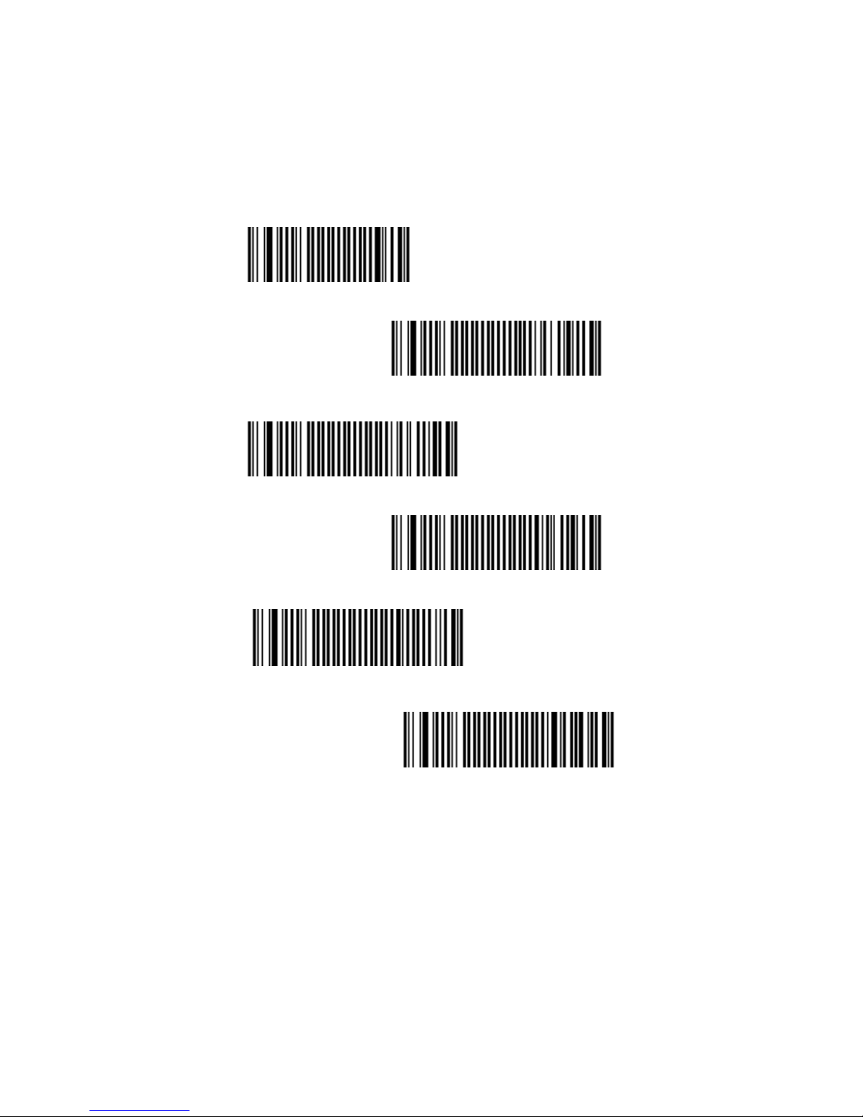
7.7.5 Postambles
The scanner can be programmed to output Barcode
data according to the following format: [BAR CODE
DATA] [POSTAMBLE STRING]
Postamble None
<CR+LF >
CR
LF
TAB
SP
Page 49
49
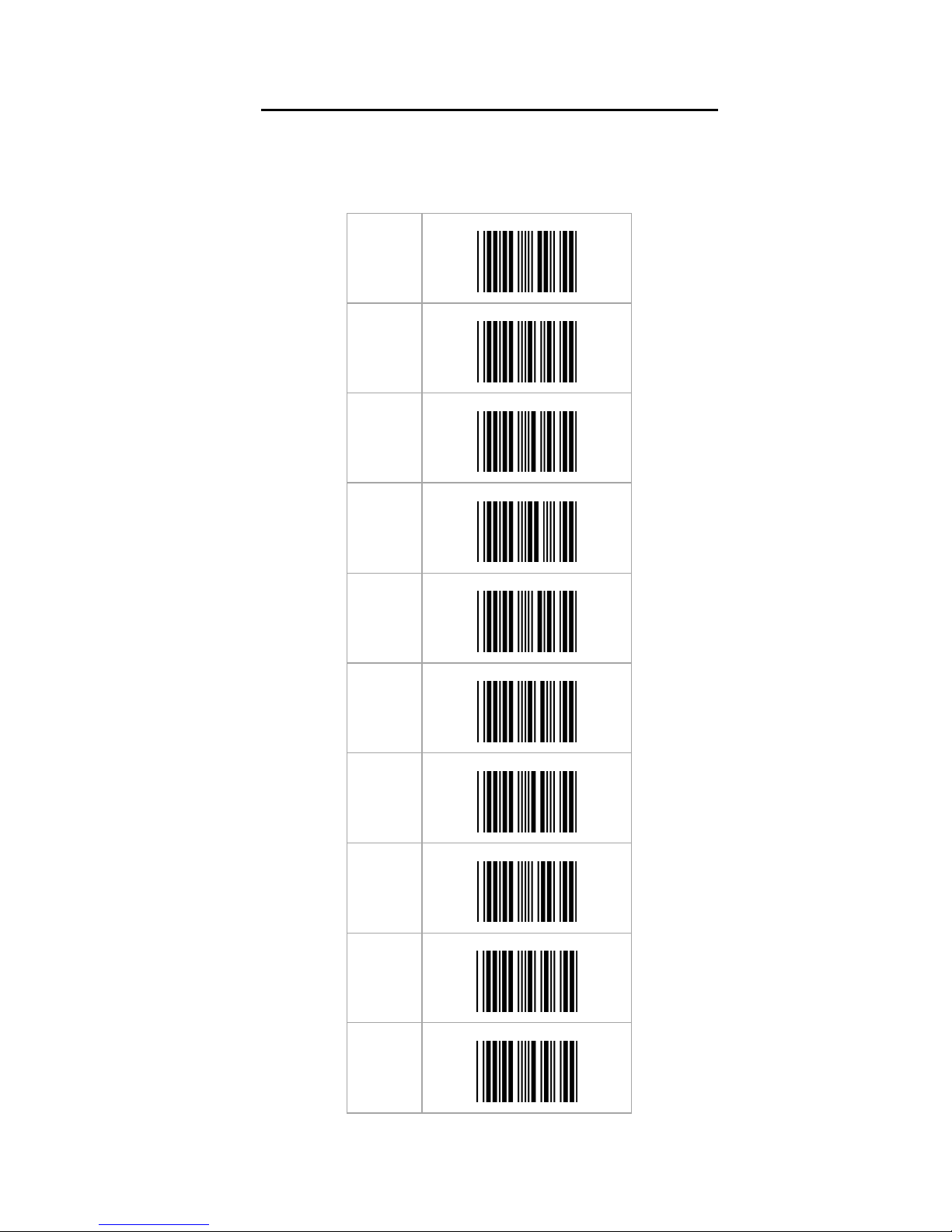
Appendixes
A. Decimal Value Table
0
1
2
3
4
5
6
7
8
9
Page 50
50
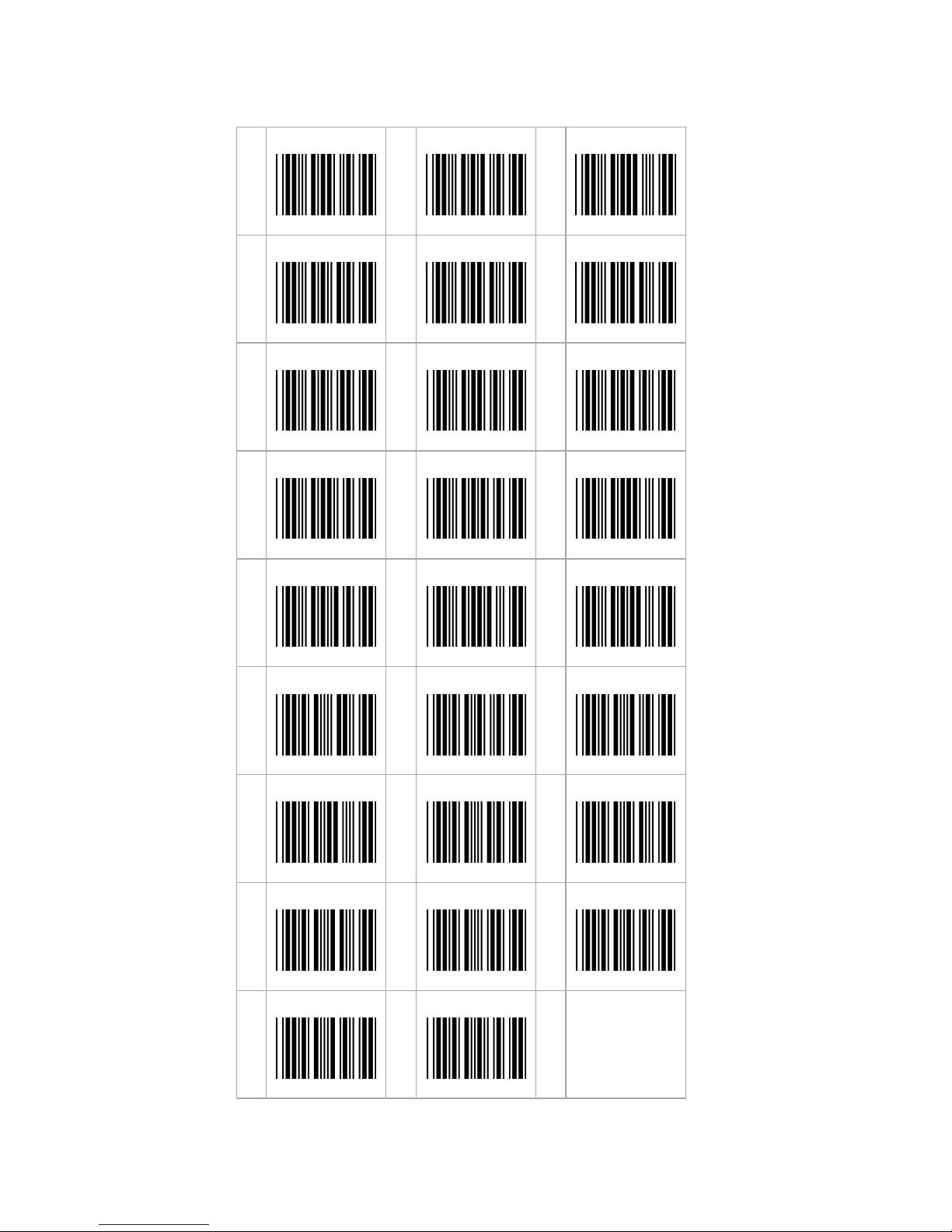
B. ASCII Table
A
B
C
D
E
F
G
H
I
J
K
L
M
N
O
P
Q
R
S
T
U
V
W
X
Y
Z
Page 51

51
C. Readable Symbologies
1D Symbologies
Symbologies Readable
Default
Enable
EAN/UPC
○ ○
UCC/EAN128
○ ○
ISBN
○
ISBT
○
Code 11
○
Code 39
○ ○
Code 93/93i
○
Code 128
○ ○
Interleaved
2 of 5
○
Matrix
2 of 5
○
Instus
trial
2 of 5
○
Standard 2 of 5
○
Codabar
○
MSI
○
Plessey
○
Telepen
○
BPO
○
Codablock
○
Informail
○
Planet
○
TLC 39
○
Postnet
○
Postal codes
○
GS1
-
128
○ GS1 CC
-
A/B/C
○
GS1 DataBar
Omnidirectional
○
GS1 DataBar
Limited
○
GS1 DataBar
Expanded
○
Page 52
52
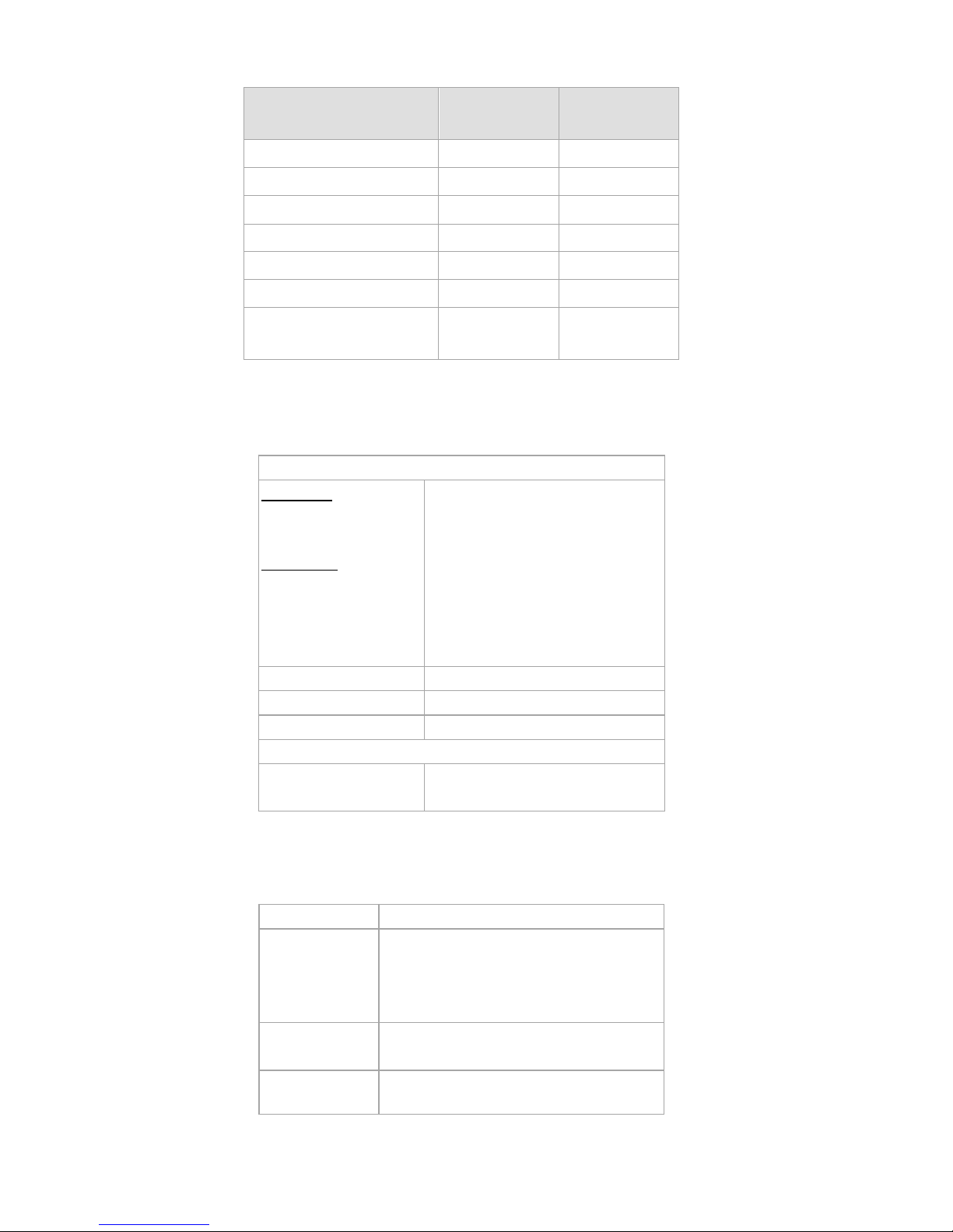
2D Symbologies
Symbologies Readable
Default
Enable
Data Matrix
○
PDF417
○
○
MicroPDF417
○
Maxi
C
ode
○
QR code
○
Aztec
○
EAN.UCC
composite
○
D. Technical Specifications
D-1 Physical Characteristics
Weight
IG-300BT
Scanner
Cradle
Accessory
KBW cable
RS232 Cable
USB Cable
AC adaptor
Approx. 210g
Approx. 105g
Approx. 75g
Approx. 123g
Approx. 67g
Approx. 125g
Material
ABS Plastic
Connector
RJ 45C 10Pin
s Cable Length
5Ft. (150mm)
Dimension
Scanner
Cradle
193x90x72mm
206x101x49mm
D-2 Performance
a) Scanner Characteristics
Light source
Visible Red light 650nm ± 10nm
Scan rate
200scans/sec auto adaptive in
linear mode
56 images/sec auto adaptive in
area mode
Optical
resolution
752 Horizontal x 480 Vertical
pixels, 256 gray levels
Scan angle
Horizontal 70°±10%
(Forward: 20°/
Backward: 50°)
Page 53
53
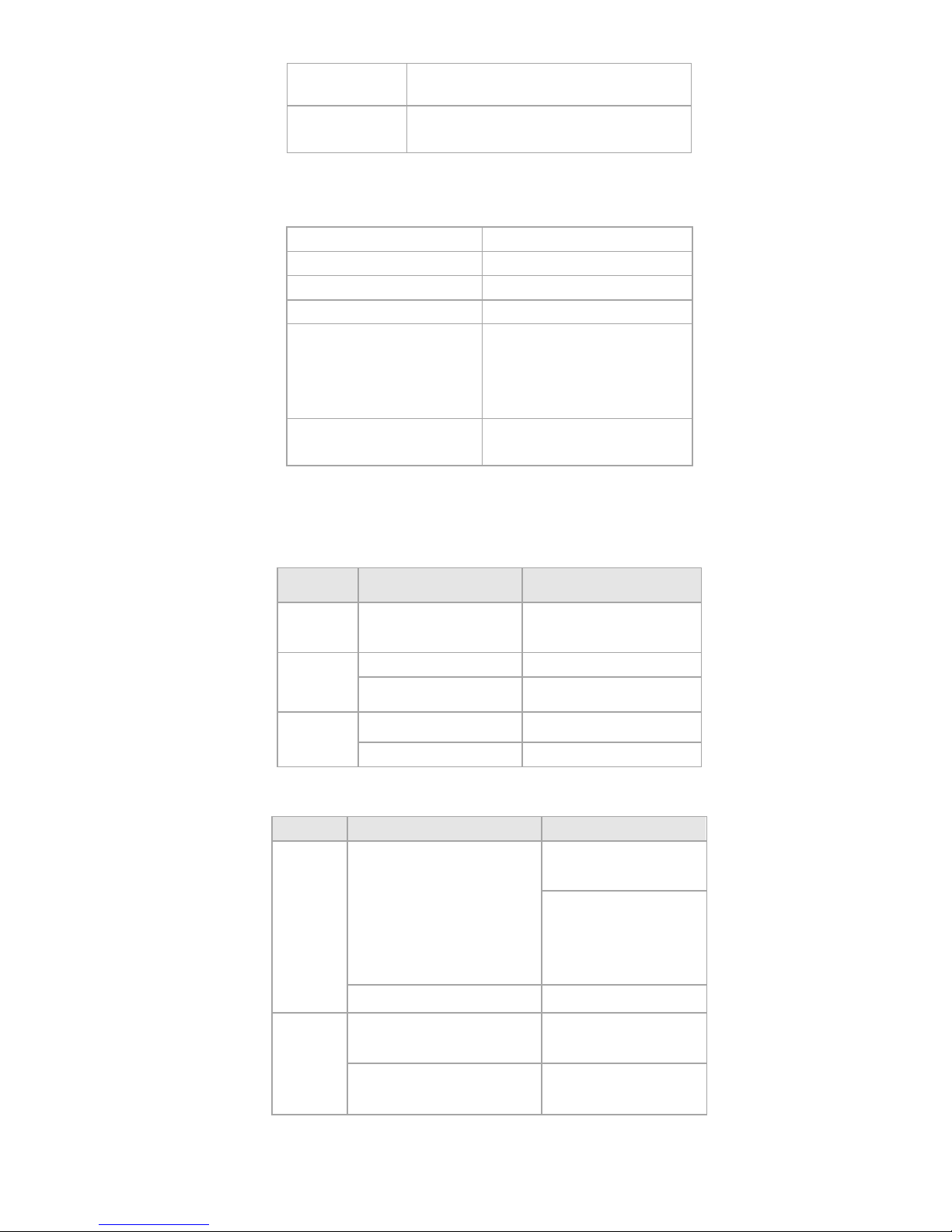
Vertical
80°±10%
(Left 40°/ Right
40°)
Interface
IG-300BT
KBW, RS-232, USB (HID KBW)
b) Bluetooth Characteristics
(for IG-300BT series)
Bluetooth Module
Bluetooth V2.0 Standard
Frequency Band
2.402GHz ~ 2.480GHz
Modulation Method
GFSK for 1Mbps
RF Output Power
Under 4dBm (Class 2)
Bluetooth distance
range
Class
2
; Up
to 10M
line of
sight
Class 1
; Up to 80M line of
sight
Data storage on BT
disconnect
20,000 scans for EAN13
D-3 Indicator LED Status
a) Cradle
Light
Signal Status
Green 1 blink
good read
and transmitted
Red
continuous on
power on
off power off
Blue
2 blink BT disconnect
continuous on
BT connected
b) Scanner
Light
Signal
Status
Green
1 blink and 1 beep
good read
and transmitted
good read
and save on
memory
(BT disconnect)
continue on battery charged full
Red
3 long blink and 3 long
beeps
memory full
3 long blink and 3 long
beeps
Into sleep mode
Page 54

54
2 blink and 2 beeps low Battery warning
2 long
blink
and 2
long
beeps
good read
but transmit fail
continue on
in charging
Blue
3 short beeps BT disconnect
2 blink per 2 second on connecting
flash
BT disconnect
before sleep
1 blink per 2 second BT connected
Red
Blue
1 blink
at the same time
and 2 beeps
setting ok
Red
Green
red and green light flash
alternately
Battery over
charged
D-4 Electrical Characteristics
Operation
Voltage
5 VDC ±5%
Current Operat
ing 450 mA (max) @ 5 VDC
Current Standby
37 mA typical @ 5 VDC
AC transformers
5.2 VDC @ 650 mA /
Input AC 100-240V
D-5 Environmental
Operating Temp
0°C to 50°C
Storage Temp.
-20°C to 70°C
Relative Humidity
0 to 95% non
-
condensing
Ambient light
100,000
Lux
(direct
sunlight)
D-6 Regulatory of Compliance
FCC, CE, RoHs
Page 55
55
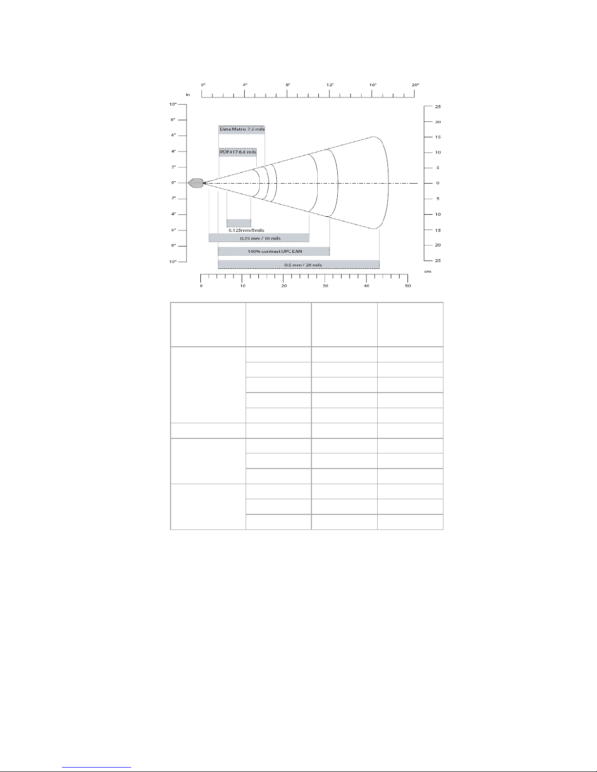
E. Scan Map
Symbology
Density
Minimum
Distance
(+/- 10%)
Maximum
Distance
(+/- 10%)
Code 39
0.125 mm
5.2 cm
12.1 cm
0.20mm
2.0 cm
21.5 cm
0.25mm
2.4 cm
26 cm
0.5m
m 4 cm
44 cm
1mm
7 cm
82 cm
UPC / EAN
0.33 mm
4 cm
31 cm
Data matrix
0.191 mm
5.3 cm
16.2 cm
0.254 mm
3.8 cm
21 cm
0.381 mm
*
28 cm
PDF417
0.16 mm
5.2 cm
14.4 cm
0.254 mm
3.5 cm
22 cm
0.381 mm
3 cm
36 cm
Page 56
56
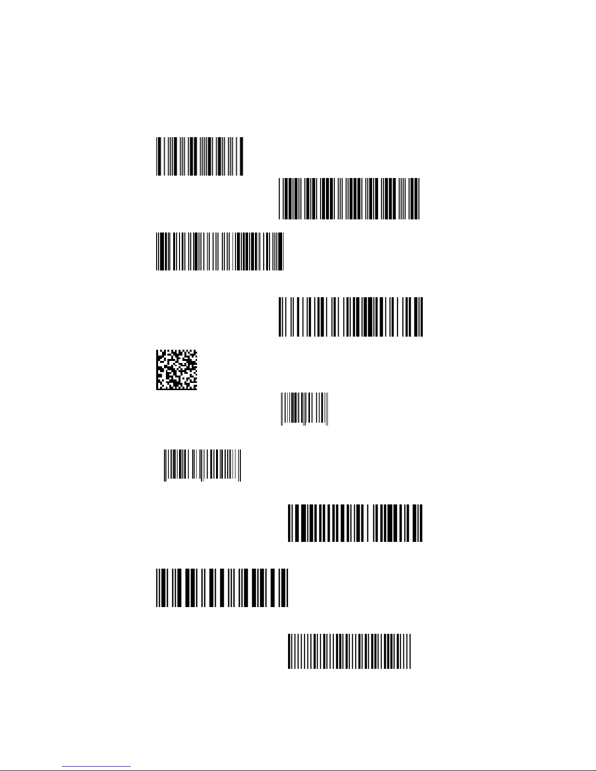
F. Test Symbologies
Scan one or more of these barcodes to test barcode
symbologies you enabled.
Codabar
Code 39
Code 93
Code 128
DataMatrix
EAN 8
1234 5670
EAN13
1 234567 890128
EAN 128
Interleaved 2 of 5
MSI code
Page 57
57
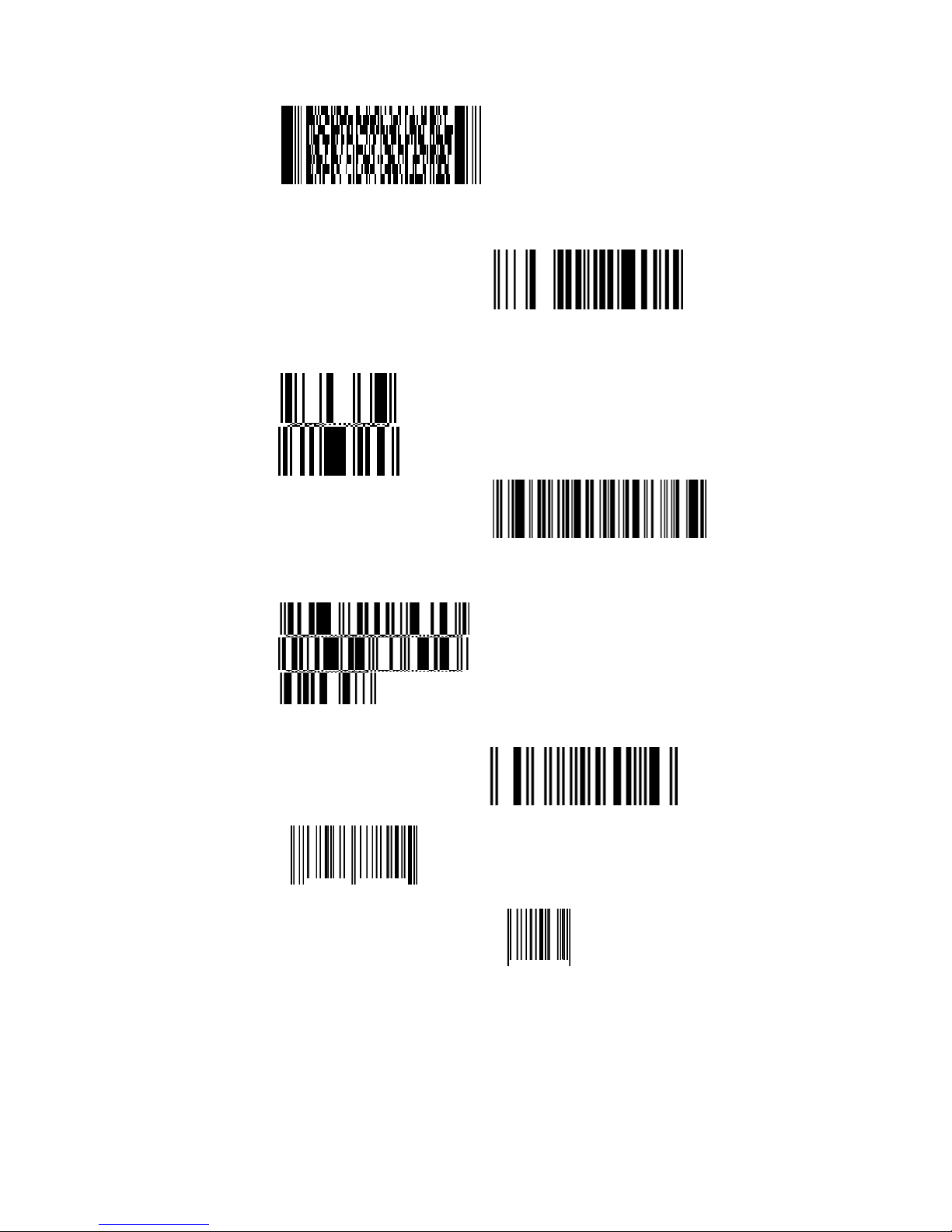
PDF417
GS1 DataBar
Omnidirectional
GS1 DataBar
Omni Stacked
GS1 DataBar Expanded
GS1DataBar Expanded
Stacked
GS1 DataBar Limited
UPC A
0
12345 67890
5
UPC E
0
12345 6
5
Page 58

58
0145-88E0041
V01
 Loading...