

OPERATOR’S MANUAL
WINCH
5,000 lb.
12039 Smith Ave.
Santa Fe Springs CA 90670
USA / 1-877-338-0999
www.championpowerequipment.com
SAVE THESE INSTRUCTIONS
Important safety instructions
are included in this manual.
MADE IN CHINA
REV 100335-20161206
100335
MODEL NUMBER

Have questions or need assistance?
Do not return this product to the store!
WE ARE HERE TO HELP!
Visit our website:
www.championpowerequipment.com
for more info:
• Product Info & Updates
• Frequently Asked Questions
Call our Customer Care Team Toll-Free at:
1-877-338-0999
• Tech Bulletins
• Product Registration
– or –
*We are always working to improve our products. Therefore, the enclosed product may differ slightly from the image on the cover.
TABLE OF CONTENTS
100335
5,000 lb.
WINCH
Introduction ....................1
Introduction ..................1
Manual Conventions ...............2
Safety Rules ...................3
Controls and Features .............. 5
Winch .....................5
Assembly ..................... 6
Mounting the Winch .............6
Wiring the Winch ...............7
Wiring Diagram ................8
Operation .....................9
General Tips for Safe Operation .......9
Self Recovery ................. 9
Winching Techniques A-Z ......... 10
Maintenance .................. 11
Lubrication ................. 11
Cable Assembly Replacement ....... 11
Specifications .................. 12
Performance Specifications ........ 12
Parts Diagram ............... 13
Parts List .................. 14
Tro u ble s hoot ing ................. 15

ENGLISH 100335
INTRODUCTION
Introduction
Congratulations on your purchase of a Champion Power Equipment (CPE) product. CPE designs, builds,
and supports all of our products to strict specifications and guidelines. With proper product knowledge,
safe use, and regular maintenance, this product should bring years of satisfying service.
Every effort has been made to ensure the accuracy and completeness of the information in this
manual, and we reserve the right to change, alter and /or improve the product and this document at any
time without prior notice.
Since CPE highly values how our products are designed, manufactured, operated and are serviced, and
also highly value your safety and the safety of others, we would like you to take the time to review this
product manual and other product materials thoroughly and be fully aware and knowledgeable of the
assembly, operation, dangers and maintenance of the product before use. Fully familiarize yourself, and
make sure others who plan on operating the product fully familiarize themselves too, with the proper
safety and operation procedures before each use. Please always exercise common sense and always err
on the side of caution when operating the product to ensure no accidents, property damage, or injury
occurs. We want you to continue to use and be satisfied with your CPE product for years to come
Record the model and serial numbers as well as date and place of purchase for future reference. Have
this information available when ordering parts and when making technical or warranty inquiries.
Champion Power Equipment Support
1-877-338-0999
Model Number
100335
Serial Number
Date of Purchase
Purchase Location
1

10033 5 ENGLISH
MANUAL CONVENTIONS
This manual uses the following symbols to help differentiate between different kinds of information.
The safety symbol is used with a key word to alert you to potential hazards in operating and owning
power equipment.
Follow all safety messages to avoid or reduce the risk of serious injury or death.
DANGER
DANGER indicates an imminently hazardous
situation which, if not avoided, will result in
death or serious injury.
WARNING
WARNING indicates a potentially hazardous
situation which, if not avoided, could result in
death or serious injury.
CAUTION
CAUTION indicates a potentially hazardous
situation which, if not avoided, may result in
minor or moderate injury.
CAUTION
CAUTION used without the safety alert
symbol indicates a potentially hazardous
situation which, if not avoided, may result in
property damage.
NOTE
If you have questions regarding your winch,
we can help. Please call our help line at
1-8 7 7- 338 - 0 9 99
2

SAFETY RULES
ENGLISH 100335
WARNING
Read this manual thoroughly before operating
your winch. Failure to follow instructions could
result in serious injury or death.
WARNING
Do not exceed the rated capacity.
DANGER
Do not use this winch for lifting or moving
people or animals.
DANGER
Keep yourself and others a safe distance to
the side of the cable when under tension.
DANGER
Never step over a cable or near a cable under
load.
WARNING
Do not use the winch to secure or hold a
vehicle for a long period of time. Do not use
the winch to secure a vehicle for transpor t.
WARNING
Disconnect the remote control and battery
leads when not in use.
WARNING
Avoid “shock loads” by using the control
switch intermittently to take up the slack in
the wire rope. “Shock loads” can far exceed
the rate capacity for the wire rope and drum.
Do not accelerate your vehicle while winching.
Loss of traction can cause a shock load on
the cable.
CAUTION
Use hook strap when handling the hook for
spooling or unspooling the wire rope.
WARNING
The wire rope may break before the motor
stalls. For heavy loads at or near rated
capacity, use a pulley block/snatch block to
reduce the load on the wire rope.
WARNING
Do not move the vehicle to pull a load
(towing) on the winch cable. This could result
in cable breakage.
3

10033 5 ENGLISH
SAFETY RULES
WARNING
When re-spooling the cable, ensure that the
cable spools in the under-wind position with
the cable entering the drum from the bottom,
not the top.
To re-spool correctly, and while wearing
gloves, keep a slight load on the cable while
pushing the remote button to draw in the
cable. Walk toward the winch not allowing the
cable to slide through your hands. Do not let
your hands get within 30 cm (12 in.) of the
winch while re-spooling. Turn off the winch
and repeat the procedure until a few feet of
cable are left. Disconnect the remote control
and finish spooling by rotating the drum by
hand with the clutch disengaged. Keep hands
clear of the fairlead and drum while the winch
is under power .
WARNING
Do not use as a hoist. Do not use for overhead
lifting.
CAUTION
Use gloves to protect hands when handling
the cable. Never let the cable slide through
your hands.
CAUTION
Duration of winching pulls should be kept as
short as possible.
If the motor becomes uncomfortably hot to
the touch, stop winching immediately and let
it cool down for a few minutes. Do not pull for
more than one minute at or near the rated load.
CAUTION
If the motor stalls, do not maintain power to
the winch.
Electric winches are designed and made for
intermittent use and should not be used in
constant duty applications.
CAUTION
Apply blocks to the wheels of the vehicle
when on an incline.
CAUTION
Never release the free-spool clutch when
there is a load on the winch.
CAUTION
Do not wrap the cable around any object and
hook it back onto itself.
4
ENGLISH 100335
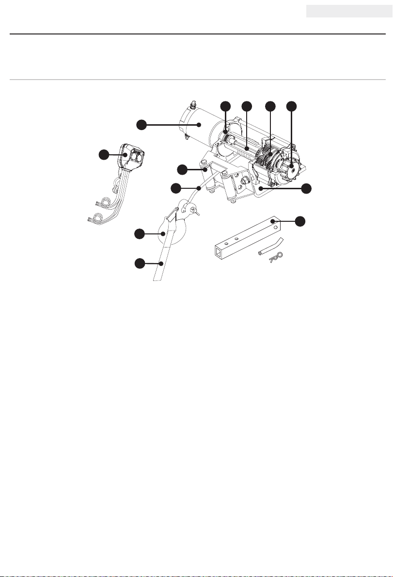
CONTROLS AND FEATURES
Read this owner’s manual before operating your winch. Familiarize yourself with the location and
function of the controls and features. Save this manual for future reference.
Winch
32
4 5
1
12
8
9
10
11
(1) Motor - 1.6 HP/1.2 kW 12V DC motor provide s
power to the planetary gear mechanism.
(2) Braking System - Braking action is automatically
applied to the winch drum when the winch motor
is stopped and there is a load on the wire rope.
(3) Winch Drum - The winch drum is the cylinder
on which the wire rope is stored. It can feed or
wind the rope depending on the remote winch
switch.
(4) Planetary Gear System - The reduction gears
conver t the winch motor power into extreme
pulling forces. This system allows high torque
while maintaining compact size and light weight.
(5) Free Spooling Clut ch - The clutch allows the
operator to manually disengage (“Out”) the
spooling drum from the gear train, free spool.
Engaging the clutch (“In”) locks the winch into
the gear system.
(6) Mounting Channel
6
7
(7) 1¼ in . ( 31,8 mm ) Hitch Adapter
(8) Roller Fairlead - When using the winch at an
angle the roller fairlead acts to guide the wire
rope onto the drum and minimize s dama ge to
the wire rope from abrasion on the winch mount
or bumper.
(9) Wire Rope - 15/ 6 4 in. x 38 ft. galvanized
aircraf t cable designed specifically for load
capacity of 5,000 lb. (2,268 kg) The wire
rope feeds onto the drum in the “under wind”
position through the roller fairlead (8) and is
looped at the end to accept the clevis hook pin.
(10) Clevis Hook – Provides a means for connecting
the looped ends of cables to an anchor.
(11) Strap – Used to assist cable feed.
(12) Remote Switch – Rocker switch with handlebar
mount for powering the rope in or out of your
winch drum.
5
10033 5 ENGLISH
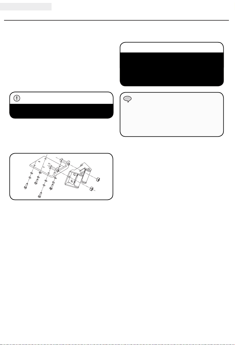
ASSEMBLY
Mounting the Winch
This CPE 5,000 lb. (2,268 kg) winch is designed
with a bolt pattern that is standard in this class
of winch. Many winch mounting kits are available
that utilize this bolt pattern for the most popular
UTV’s and ATV’s. If you cannot find a kit locally,
contact CPE and we will provide you with the
name of a dealer.
CAUTION
Mounting bolts must be SAE grade 5 or better
and torque to 34 ft. lb.
1. Insert M10x20 bolts through the mounting
channel holes and attach the roller fairlead to
the mounting channel with the M10 lock nuts
provided.
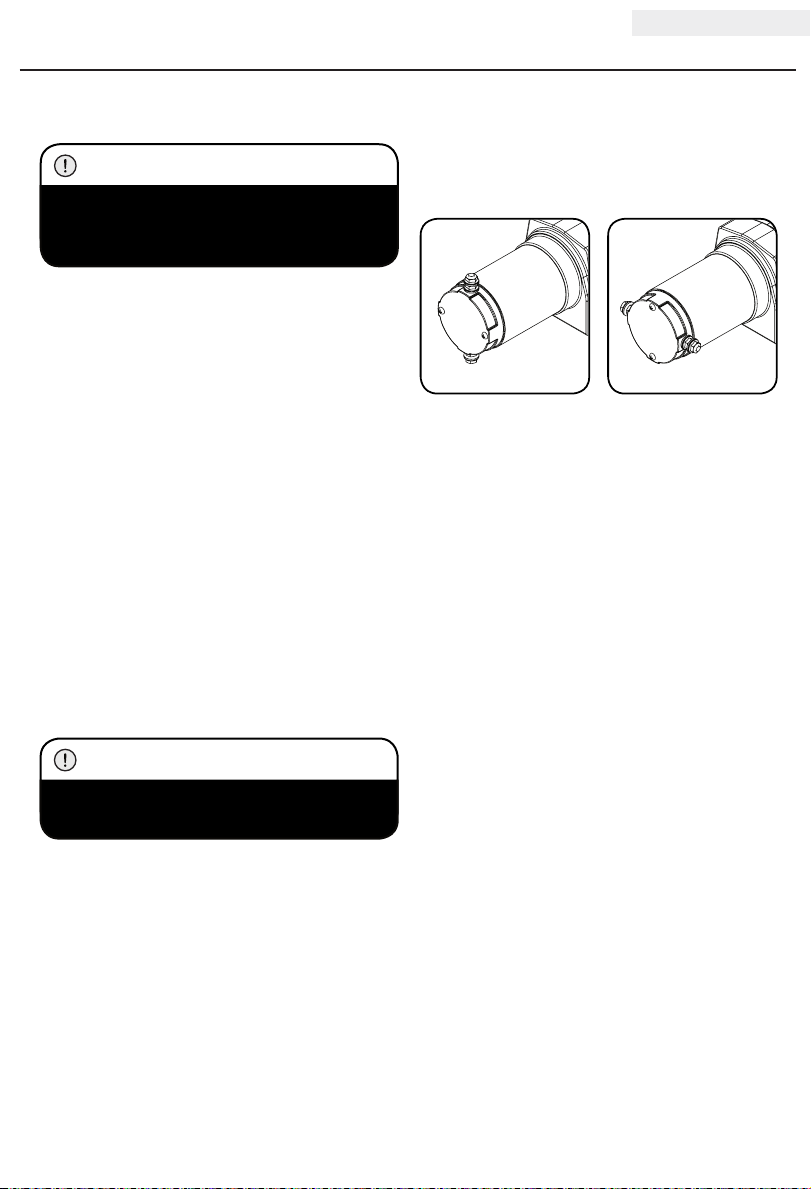
Mounting the Winch Cont’d.
CAUTION
If utilizing a mounting plate, ensure that
the three major sections (motor, drum and
gear housing) are properly aligned. Proper
alignment of the winch will allow for even
distribution of the full rated load.
NOTE
The type of vehicle to which the winch and
mounting channel will be applied, will dictate
the type of mounting kit that should be
used (Speed Mount Hitch Adapter, Standard
Mounting Channel, or Specialty Mounting Kit).
2. Tu rn th e winc h upsi d e down . Place the
mounting channel on the winch, making sure
the winch is centered in the middle of it.
3. Thread the M8x25 bolts through the M8 flat
and lockers washers, and then thread through
the mounting channel. Tighten the bolts. DO
NOT over tighten.
4. Tu rn wi n ch r i g ht si de up . Disengage the
clutch by moving the Cam Ring to the “Out”
position. Release the wire rope and pull
through the roller fairlead.
5. Attach the clevis hook to the cable, and then
hand strap to the clevis hook.
6
ASSEMBLY
ENGLISH 100335
Winch Wiring
CAUTION
Never route electrical cables across any sharp
edges, through or near moving parts, or near
parts that become hot.
1. Connect the battery leads. FOR WINCH TO
FUNCTION PROPERLY: Connect the red (+)
lead of the remote to the red (+) terminal of
the vehicle’s 12 volt battery. Connect the
black (–) lead of the remote to the black (– )
terminal of the vehicle’s 12 volt battery.
2. Attach the remote lead to the winch and test
for proper operation.
3. Check for proper drum rotation. Pull and
turn the clutch knob to the “out” position
(Free spooling). Pull out some cable from the
drum, and then turn the clutch knob to the
“In” position to engage the gears. Press the
cable out button on the switch. If the drum
is turning and releasing more cable then
your connections are accurate. If the drum
is turning and collecting more cable then
reverse the leads on the motor. Repeat and
check rotation.
Winch Wiring Cont’d.
With some applications the motor leads may need
to be rotated to avoid interference with other
components.
CAUTION
Battery cables should not be drawn taut.
Leave some slack for cable movement.
7

10033 5 ENGLISH
Wiring Diagram
Black
Red
ASSEMBLY
Negative (–)
Positive (+)
Remote
Control
Black
Negative (–)
Positive (+)
Red
8
OPERATION
ENGLISH 100335
General Tips for Safe Operation
Your 100 335 winch is rated a t a 5,000 lb.
(2,268 kg) capacity in first layer (max) when
spooling the first rope layer on the drum. Overloads
can damage the winch, motor and/or wire rope. For
loads over 2,500 lb. (1134 kg) we recommend the
use of the pulley block/snatch block to double the
wire rope line. This will aid in two ways:
(a) reduce the number or rope layers on the drum,
as well as,
(b) reduce the load on the wire rope by as much
as 50%.
When doubling the line back to the vehicle,
attach to the tow hook, frame or other load bearing
part. The vehicle engine should be kept running
during operation of the winch to minimize battery
drain and maximize power and speed of the winch.
If the winch is used for a considerable time with
the engine off the battery may be drained and too
weak to restart the motor.
Get to know your winch before you actually need to
use it. We recommend that you set up a few test
runs to familiarize yourself with rigging techniques,
the sounds your winch makes under various loads,
the way the cable spools on the drum, etc.
Inspect the wire rope and equipment before each
use. A frayed or damaged rope shall be replaced
immediately. Use only manufacturer’s identical
replacement rope with the exact specifications.
Inspect the winch installation and bolts to ensure
that all bolts are tight before each operation. Store
the remote control inside your vehicle in a place
that it will not be damaged.
Any winch that appears to be damaged in any way,
is found to be worn, or operates abnormally MUST
BE REMOVED FROM SERVICE UNTIL REPAIRED.
It is recommended that the necessary repairs be
made by a manufacturer’s authorized repair facility.
Pull only on areas of the vehicle as specified by
the vehicle manufacturer. Only attachments and/
or adapters supplied by the manufacturer are to be
used.
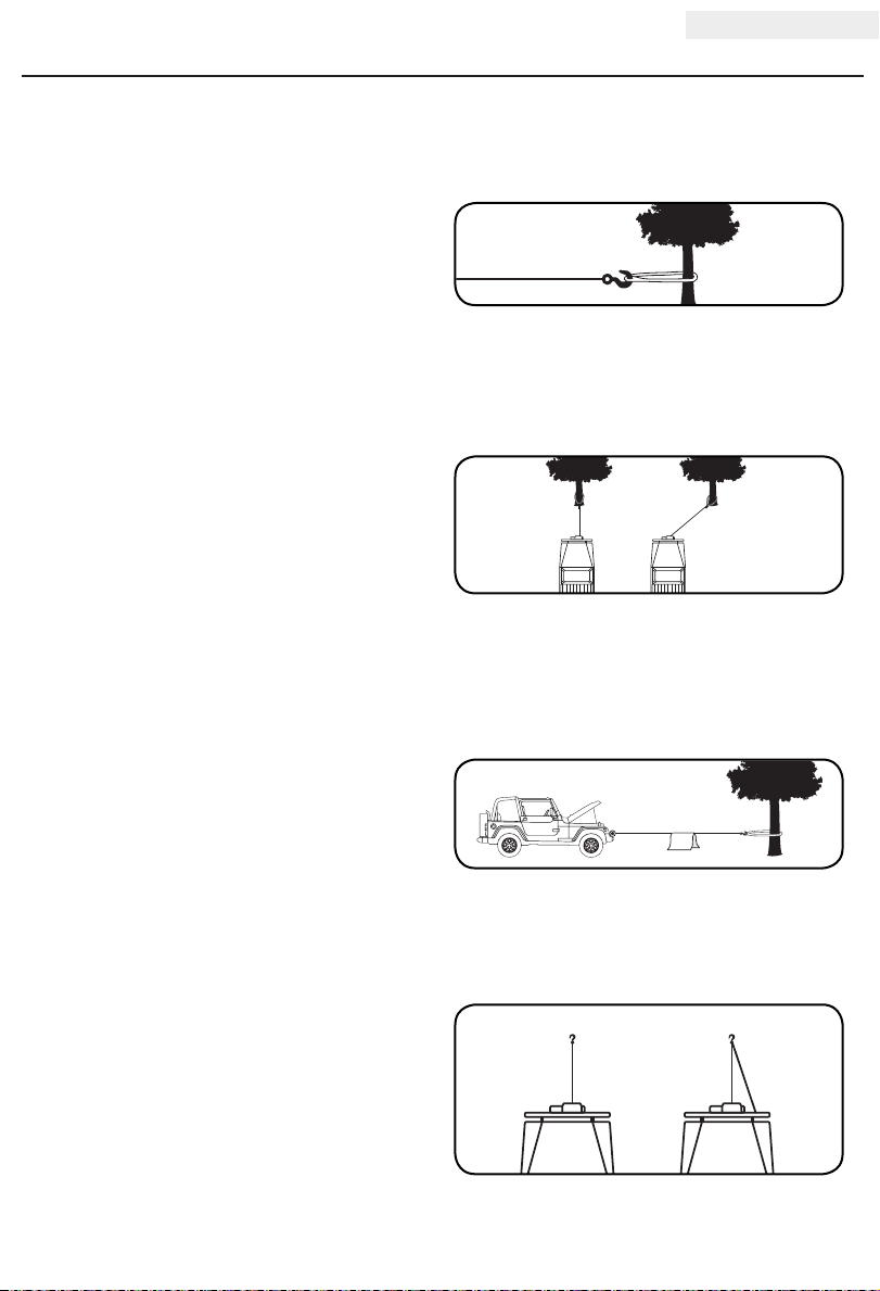
Self Recovery
Locate a suitable anchor such as a strong tree trunk
or boulder. Always use a sling as an anchor point.
Your winch is equipped with a roller fairlead to
help guide the wire rope and to reduce binding on
short side pulls. Do not winch from an acute angle
as the wire rope will pile up on one side of the
drum causing damage to wire rope and the winch.
RIGHT WRONG
Short pulls from an angle can be used to straighten
the vehicle. Long pulls should be done with the wire
rope at a 90° angle to the winch/vehicle.
When pulling a heavy load, place a blanket or jacket
over the wire rope 5 to 6 ft. (1.5 to 1.8 m) from the
hook.
In the event of a broken cable it will dampen the
snap back. For additional protection open the
hood of the vehicle. For pulls over 2,500 lb.
(1134 kg), we recommend the use of the snatch
block/pulley block to double line the wire rope.
SINGLE LINE DOUBLE LINE
This reduces the load on the winch and the strain
on the rope by approximately 50%.
9

10033 5 ENGLISH
OPERATION
Winching Techniques A-Z
(a) Take time to a s sess y o ur si tuat ion a n d pl an
your pull.
(b) Put on gloves to protect your hands.
(c) Disengage the clutch to allow free- spooling
and also save battery power.
(d) Attach the hook strap to the clevis hook.
(e) Pull out the wire rope to your desired anchor
point using the hook strap.
(f) Secure the clevis hook to the anchor point:
Sling, chain or snatch block. Do not attach
the hook back onto the wire rope.
(g) Engage the clutch.
(h) Connect the remote control to the winch. If
you are going to control the winch from inside
your vehicle then pass the remote through an
open window to avoid the wires being pinched
in the door.
(i) Start your engine to ensure power is being
replenished to the battery.
(j) Drape a blanket or jacket over the wire
rope approximately 5 to 6 ft. (1.5 to 1.8 m)
from the hook. Open the hood for added
protection.
(k) Power in the wire rope guiding the wire under
tension to draw up the slack in the wire. Once
the wire is under tension, stand clear. Never
step over the wire rope.
(l) Double check your anchors and make sure all
connections are secure.
(m) Inspect the wire rope. Make sure there are at
least 5 wraps of wire rope around the winch
drum.
(n) Clear the area. Make sure all spectators stand
clear and that no one is directly in front or
behind the vehicle or anchor point.
(o) Begin winching. Be sure that the wire rope
is winding evenly and tightly around the
drum. The vehicle that is being winched can
be slowly driven to add assistance to the
winching process. Avoid shock loads; keep
the wire rope under tension.
Winching Techniques A-Z Cont’d.
(p) The vehicle to be winched should be placed
in neutral and the emergency brake released.
Only release the brake pedal when under full
tension. Avoid shock loads to the winch. This
can damage the winch, rope and vehicle.
(q) The winch is meant for intermittent use.
Under full load with a single line rig do not
power in for more than a minute without
letting the motor cool down for a few minutes
and then resume the winching operation.
(r) The winching operation is complete once the
vehicle is on stable ground and is able to
drive under its own power.
(s) Secure the vehicle. Be sure to set the brakes
and place the vehicle in park.
(t) Release the tension on the wire rope. The
winch is not meant to hold the vehicle for
long periods of time.
(u) Disconnect the wire rope from the anchor.
(v) Rewind the wire rope. Make sure that any wire
already on the drum has spooled tightly and
neatly. If not, draw out the wire and re-spool
from the point where the rope is tight.
(w) Keep your hands clear of the winch drum and
fairlead as the wire rope is being drawn in.
(x) Secure the hook and hook strap.
(y) Disconnect the remote control and store in a
clean, dry place.
(z) Clean and inspect connections and mounting
hardware for next winching operation.
10

MAINTENANCE
ENGLISH 100335
The owner/operator is responsible for all periodic
maintenance.
WARNING
Never operate a damaged or defective winch.
WARNING
Improper maintenance will void your warranty.
Complete all scheduled maintenance in a timely
manner. Correct any issue before operating the
winch.
NOTE
For ser vice or parts assistance, contact our
help line at 1-87 7- 3 38 - 0 9 99
Lubrication
All moving parts within the electric winch having
been lubricated using high temperature lithium
grease at the factory. No internal lubrication is
required. Lubricate cable assembly periodically
using a light penetrating oil.
Cable Assembly Replacement
It is recommended that any modifications be
performed by a manufacturer’s authorized repair
facility, and that only manufacturer-supplied parts
be used.
1. Move the clutch to the “Out” position.
2. Extend cable assembly to its full length. Note
how the existing cable is connected to the
inside of the drum.
3. Remove old cable Assembly and attach new
one.
4. Retract Cable Assembly onto drum being
careful not to allow kinking.
11

10033 5 ENGLISH
SPECIFICATIONS
Performance Specifications
– Rated Pull ..................................... 5,000 lb. (2,268 kg)
– Gear Reduction Ratio .......................................166:1
– Motor ........................... Permanent Magnet 1.6 HP/1.2 kW (12V DC)
– Duty Cycle ..........................................Intermittent
– Drum Size ......................2 in. (D) x 3.2 in. (L) [50.8 mm(D) x 81 mm(L)]
– Cable ........................ 15/64 in. (D) x 38 ft. (L) [6 mm(D) x 11,6 m(L)]
– Gross Weight ..................................... 34.2 lb. (15.5 kg)
– Net Weight ........................................ 32 lb. (14.5 kg)
– Height ...........................................5 in. (12.7 cm)
– Width ..........................................4.6 in. (11.6 cm)
– Length ........................................ 14.6 in. (37.1 cm)
– Bolt Pattern. . . . . . . . . . . . . . . . . . . . . . . . . . . . . . 4.9 in. x 3 in. (12.4 cm x 7.6 cm)
Line Speed and Motor Current (First Layer)
Line Pull
Line Speed (12V DC)
Motor Current (12V DC) A 28 80 130 180 230 260 290
Running Time* Minutes 1 1 1 1 1 1 1
Cooling Time** Minutes 5 5 5 5 5 5 5
LB 0 100 0 2000 3000 4000 4500 5000
KG 0 454 907 1361 1814 2041 2268
FPM 12.8 9.8 8.5 6.9 5.2 4.3 3.3
MPM 3.9 3.0 2.6 2.1 1.6 1.3 1.0
*If the mo tor be come s uncomfortably hot to the touch, s top win ching imme diately and let i t cool down
for 5 minutes. Do not pull for more than one minute at or ne ar the rated load.
**Electric winches are desig ned and made f or intermittent use and should not b e used in cons tant
duty applications.
Line Pull and Cable Capacity Per Layer
Line of Cable 1 2 3 4
Rated Line Pull
Cable Capacity
It is recommended to use double line and snatch block for pulling loads over
LB 5000 4128 3515 3060
KG 2268 1872 1594 1388
FT 8.5 19 31.2 38
M 2.6 5.8 9.5 11.6
2,500 lb. (1134 kg).
12

SPECIFICATIONS
2
8
2
3
4
5
6
7
8
9
1
0
1
1
1
2
1
3
1
4
1
5
1
5
1
4
2
3
2
1
2
2
2
1
2
0
1
9
1
8
1
8
1
7
1
7
1
4
1
6
2
4
2
5
2
6
2
9
2
7
1
2
8
2
9
4
5
4
4
5
0
5
1
5
2
5
3
5
5
5
4
3
0
3
1
3
2
3
3
3
4
3
5
3
6
3
7
3
8
4
0
4
1
3
9
46
4
5
44
43
4
7
4
8
49
4
2
5
6
5
7
5
8
5
9
6
0
6
1
6
2
Parts Diagram
ENGLISH 100335
13

10033 5 ENGLISH
Parts List
# Part Number Description
450100-BF
01
450001 Coupling, I 1
02
450002 Spring, Coupling 1
03
450003 Coupling, II 1
04
400200-BF
05
450004-BF
06
450005-A Gear Ring 1
07
450006
08
450007
09
450008
10
450009 Gear-Input, Sun 1
11
450010-BF Gear, Fixed - Black Flat 1
12
250021 Clutch Bushing 1
13
250002 Flat Washer ø6 6
14
450011
15
450012
16
450013 Seal 2
17
450014 Friction Wa she r 2
18
450015 Retaining Ring 1
19
450016 O-Ring Seal 1
20
450017 Drum Bushing 2
21
400018 Haxagonal Shaft 1
22
400008 Tie Bar ø10 2
23
450800 Cable Assembly 1
24
C20002 1/4 In. Clevis Hook 1
25
41002 2 Yellow Strap 1
26
400010 Tie Bar ø8 1
27
450026
28
450027 Flat Washer ø4 2
29
450031
30
450029 Spring
31
GB2760BB06002-SS
32
250019 Axis Support Bushing
33
Motor Assembly - Black
Flat
Drum Assembly - Black
Flat
Gear Housing/End Bearing
- Black Flat
Gear Carrier Assembly,
Output
Gear Carrier Assembly,
Intermediate
Gear Carrier Assembly,
Input
Hexagon Socket Head
Screw M6 x 25
Hexagon Socket Head
Screw M6 x 100
Hexagon Socket Head
Screw M4 x 25
Cross Recess Pan Head
Screw M6 x 8
Radial Ball Bearing 6002
Sealed
Qty
# Part Number Description
450032 Cam Clutch Gear 1
34
1
250012 Large Spring 1
35
450033-BF Clutch Cover - Black Flat 1
36
GB2760BB16002-SS
37
1
1
1
1
1
4
2
2
1
1
1
1
250016-BF Clutch Cap - Black Flat 1
38
250011 Retaining Ring Clip
39
250017 Lock Washer ø6
40
250018 Cap Screw M6 x 16 1
41
451500 Switch Assembly 1
42
300018
43
300020 Lock Washer ø8 6
44
300019 Flat Washer ø8 6
45
300021 Lock Nut M8 2
46
200027-BF
47
250037 5/8 In. Hitch Pin 1
48
250038 R-Pin 1
49
450021
50
250025 -BF
51
400009
52
250029-BF Roller Fairlead - Black Flat 1
53
250035 Lock Washer ø10 2
54
250036 Lock Nut M10
55
450500A Control Switch - Black
56
300037-BF
57
400025 Nut M5 2
58
400026-BF
59
400024 Lock Washe r Ø5 2
60
400023 Flat Washer Ø5 2
61
400022
62
Radial Ball Bearing 16002
Sealed
Hexagon Head Bolt
M8 x 60
1.25 In. Hitch Adapter Black Flat
Hexagon Head Bolt
M8 x 25
Mounting Channel Black Flat
Hexagon Head Bolt
M10 x 20
Control Switch Mounting
Plate - Black Flat
Handleba r Switch Clamp
- Black Flat
Hexagon Socket Head
Screw M5 x 25
Qty
1
1
1
2
1
4
1
2
2
1
1
2
2
14

TROUBLESHOOTING
Problem Cause Solution
Loose battery cable connections Tighten nuts on all cable connections
Defective switch assembly Replace switch assembly
Motor does not turn on
Motor runs but cable
drum does not turn
Motor runs slowly or
without normal power
Motor overheating Winch running time too long Allow winch to cool down periodically
Motor runs in one
direction only
Defective motor
Water has entered motor
Clutch not engaged
Insufficient current or voltage
Loose or corroded bat tery cable
connections.
Defective switch assembly Replace switch assembly
For further technical support:
Tec hni cal Ser v ice
Mon – Fri 8 :30 AM – 5:00 PM (PST/PDT)
Toll Fre e : 1- 877- 3 3 8 - 0 9 9 9
tech@ championpowerequipment.com
Check for voltage at armature port with switch
pressed. If voltage is present, replace motor
Allow to drain and dry. Run in short bursts without
load until completely dry
Move clutch to the "In" position. If problem persists, a
qualified technician needs to check and repair
The battery is weak, recharge. Run winch with vehicle
motor running (battery should have a strong charge)
Clean, tighten, or replace
ENGLISH 100335
15

WARRANTY
WARRANTY
CHAMPION POWER EQUIPMENT
2 YEAR LIMITED WARR ANTY
Warranty Qualifications
Champio n Powe r Equipment (CP E) will re giste r this wa rrant y
upon re ceipt of your Wa rrant y Regi stra tion Ca rd and a copy
of your sales receip t from one of C PE’s ret ail loc ations as
proof of purchase.
Please submit your warrant y registration and yo ur proof of
purchase within ten (10) days of the date of purchase.
Repair/Replacement Warranty
CPE warrant s to the original purcha ser that the m echanic al
and electrical compo nents will be free of d efect s in
material and wo rkmanship for a perio d of t wo yea rs (p art s
and labor) fro m the or iginal da te of purchase and 180
days (p art s and la bor) fo r comm ercial a nd indus trial us e.
Transpor tati on char ges on product subm itted for rep air or
replacement un der this warr anty a re the sole responsibility
of the pu rchas er. This wa rrant y only applies to the o riginal
purchaser and is not transferable.
Do Not Return The Unit To The Place Of
Purchase
Conta ct CPE ’s Technical S ervice and CPE will tr ouble shoot
any iss ue via phone or e-m ail. If the proble m is not
corre cted b y this me thod, C PE will, at its option, aut horize
evaluati on, rep air or r eplace ment of the defective p art or
component at a CPE S ervice Cen ter. CPE will provid e you
with a ca se numb er fo r warr anty ser vice. Please keep it
for futu re refe rence . Repair s or r eplace ments without prior
authorization , or at an unauthorized repair facility, will not
be covered by this warranty.
Warranty Exclusions
This warrant y doe s not c over t he following rep airs an d
equipment:
Normal Wear
Products with mechanical and electrical components need
periodic parts and service to perform well. This warranty does
not cover repair when normal use has exhausted the life of a
part or the equipment as a whole.
Installation, Use and Maintenance
This warrant y will not apply t o par ts and /or labo r if the
product is de emed t o have b een mis used, neglec ted,
involved in an ac cident, a bused, load ed bey ond the
product’s limit s, mo dified, installe d impro perly or
connec ted incorrectly to any elect rical c ompon ent. Normal
maintenan ce is not cove red by this warrant y and is not
require d to be p erformed at a fa cility or by a pe rson
authorized by CPE.
Other Exclusions
This warranty excludes:
– Cosmetic defects such as paint, decals, etc.
– Wear items su ch as filter elements, o -rings , etc.
– Acces sor y pa rts s uch as star ting ba tteri es, and storage
covers.
– Failures due to ac ts of G od and other force m ajeure
events beyond the manufacturer’s control.
– Proble ms caused by part s that are not origina l
Champion Power Equipment parts.
Limits of Implied Warranty and
Consequential Damage
Champio n Powe r Equipment disclaims any ob ligation to
cover a ny los s of time, use of this product , freig ht, or a ny
incident al or co nsequ ential claim by anyo ne fro m using
this pro duct. T HIS WARRANT Y IS IN LIEU OF ALL OTHER
WARRAN TIES, E XPRES S OR IMPLIED, INCLU DING
WARRAN TIES OF M ERCHAN TABILIT Y OR FI TNESS F OR A
PARTICUL AR P URPOSE.
A unit provided as an ex change will be subj ect to the
warra nty of the original unit . The le ngth of the w arran ty
governin g the e xchange d unit will r emain calculated by
reference to the purchase date of the original unit.
This warrant y give s you c ert ain lega l right s which may
change f rom state to state or pro vince to provin ce. Your
state or pro vince ma y also have oth er righ ts you may be
entitled to that are not listed within this warranty.
Contact Information
Address
Champion Power Equipment, Inc.
Customer Service
12039 Smith Ave.
Santa Fe Springs, CA 90670 USA
www.championpowerequipment.com
Customer Service
Mon – Fri 8:30 AM – 5:00 PM (PST/PDT)
Toll Fre e : 1-8 77- 338 - 09 99
info@ cham pionpow erequip ment.co m
Fax no. : 1-562-236- 9429
Technical Service
Mon – Fri 8:30 AM – 5:00 PM (PST/PDT)
Toll Fre e : 1-8 77- 338 - 09 99
tech@ championpowerequipment.com
24/ 7 Tech S uppo rt : 1-562 -204 -1188
 Loading...