


OWNER’S MANUAL
12039 Smith Ave.
Santa Fe Springs CA 90670
USA / 1-877-338-0999
www.championpowerequipment.com
SAVE THESE INSTRUCTIONS
Important Safety Instructions
are included in this manual.
MADE IN CHINA
REV 100129-20180803
100129
MODEL NUMBER
ATV/UTV Winch Kit
4700 lb. Winch

Have questions or need assistance?
Do not return this product to the store!
WE ARE HERE TO HELP!
Visit our website:
www.championpowerequipment.com
for more info:
• Product Info & Updates
• Frequently Asked
Call our Customer Care Team Toll-Free at:
Questions
1-877-338-0999
• Tech Bulletins
• Product Registration
– or –
Parts Ordering:
Mon – Fri 8 :30 AM – 5:00 PM (PST/PDT)
Toll Fre e : 1- 877-3 3 8 - 099 9
WARNING: Cancer and Reproductive Harm – www.P65Warnings.ca.gov
*We are always working to improve our products. Therefore, the enclosed product may differ slightly from the image on the cover.
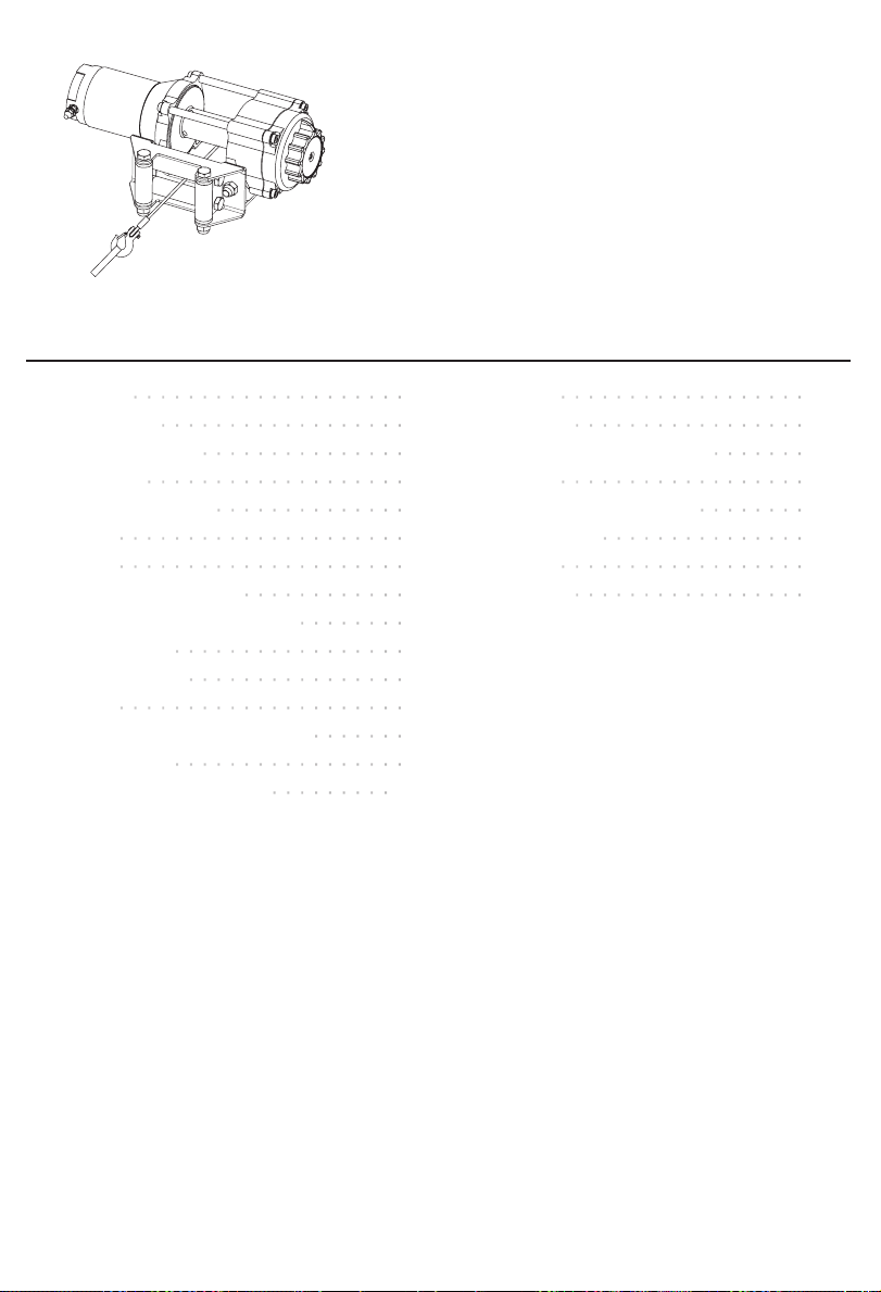
TABLE OF CONTENTS
100129
4700 lb. Winch
ATV/UTV Winch Kit
Introduction ....................1
Introduction ..................1
Manual Conventions ...............2
Safety Rules ...................3
Controls and Features ..............5
Winch .....................5
Assembly ..................... 6
Assembling the Winch ............6
Mounting the Remote Control ........6
Winch Wiring .................7
Wiring Diagram ................8
Operation .....................9
General Tips for Safe Operation .......9
Self Recovery ................. 9
Winching Techniques A-Z ......... 10
Maintenance .................. 11
Lubrication ................. 11
Cable Assembly Replacement ....... 11
Specifications .................. 12
Performance Specifications ........ 12
Parts Diagram ............... 13
Parts List .................. 14
Tro u ble s hooti ng ................. 15

ENGLISH 100129
INTRODUCTION
Introduction
Congratulations on your purchase of a Champion Power Equipment product. Champion Power
Equipment and Champion Engine Technology designs, builds, and supports all of our products to strict
specifications and guidelines. With proper product knowledge, safe use, and regular maintenance, this
product should bring years of satisfying service.
Every effort has been made to ensure the accuracy and completeness of the information in this
manual, and we reserve the right to change, alter and /or improve the product and this document at any
time without prior notice.
Since CPE/CET highly value how our products are designed, manufactured, operated and are serviced,
and also highly value your safety and the safety of others, we would like you to take the time to review
this product manual and other product materials thoroughly and be fully aware and knowledgeable
of the assembly, operation, dangers and maintenance of the product before use. Fully familiarize
yourself, and make sure others who plan on operating the product fully familiarize themselves too, with
the proper safety and operation procedures before each use. Please always exercise common sense
and always error on the side of caution when operating the product to ensure no accidents, proper ty
damage, or injury occurs. We want you to continue to use and be satisfied with your CPE/CET product
for years to come.
Record the model and serial numbers as well as date and place of purchase for future reference. Have
this information available when ordering parts and when making technical or warranty inquiries.
Champion Power Equipment Support
1-877-338-0999
Model Number
100129
Serial Number
Date of Purchase
Purchase Location
1

100129 ENGLISH
MANUAL CONVENTIONS
This manual uses the following symbols to help differentiate between different kinds of information.
The safety symbol is used with a key word to alert you to potential hazards in operating and owning
power equipment.
Follow all safety messages to avoid or reduce the risk of serious injury or death.
DANGER
DANGER indicates an imminently hazardous
situation which, if not avoided, will result in
death or serious injury.
WARNING
WARNING indicate s a potentially hazardous
situation which, if not avoided, could result in
death or serious injury.
CAUTION
CAUTION indicates a potentially hazardous
situation which, if not avoided, may result in
minor or moderate injury.
CAUTION
CAUTION used without the safety alert
symbol indicates a potentially hazardous
situation which, if not avoided, may result in
property damage.
NOTE
If you have questions regarding your winch,
we can help. Please call our help line at
1-8 7 7- 338 - 0 9 99
2
SAFETY RULES
ENGLISH 100129
WARNING
Read this manual thoroughly before operating
your winch. Failure to follow instructions could
result in serious injury or death.
WARNING
Do not exceed the rated capacity.
DANGER
Do not use this winch for lifting or moving
people or animals.
DANGER
Keep yourself and others a safe distance to
the side of the cable when under tension.
DANGER
Never step over a cable or near a cable under
load.
WARNING
Do not use the winch to secure or hold a
vehicle for a long period of time. Do not use
the winch to secure a vehicle for transpor t.
WARNING
Disconnect the remote control and battery
leads when not in use.
WARNING
Avoid “shock loads” by using the control
switch intermittently to take up the slack in
the cable. “Shock loads” can far exceed the
rate capacity for the cable and drum.
Do not accelerate your vehicle while winching.
Loss of traction can cause a shock load on
the cable.
WARNING
Batteries contain acid and produce explosive
gases.
WARNING
The cable may break before the motor stalls.
For heav y loads at or near rated capacity, use
a pulley block /snatch block to reduce the load
on the cable.
WARNING
Do not move the vehicle to pull a load
(towing) on the winch cable. This could result
in cable breakage.
WARNING
Pull only on areas of the vehicle as specified
by the vehicle manufacturer.
3
Keep sparks, flames and cigarettes away from
batteries at all times. Wear safety glasses and
protect the eyes at all times. Do not lean over
the batteries during operation.

100129 ENGLISH
SAFETY RULES
WARNING
When re-spooling the cable, ensure that the
cable spools in the under-wind position with
the cable entering the drum from the bottom,
not the top.
To re-spool correctly, and while wearing
gloves, keep a slight load on the cable while
pushing the remote button to draw in the
cable. Walk toward the winch not allowing the
cable to slide through your hands. Do not let
your hands get within 12 in. (30.5 cm) of the
winch while re-spooling. Turn off the winch
and repeat the procedure until a few feet of
cable are left. Disconnect the remote control
and finish spooling by rotating the drum by
hand with the clutch disengaged. Keep hands
clear of the fairlead and drum while the winch
is under power.
WARNING
Do not use as a hoist. Do not use for overhead
lifting.
CAUTION
Use gloves to protect hands when handling
the cable. Never let the cable slide through
your hands.
CAUTION
Duration of winching pulls should be kept as
short as possible.
If the motor becomes uncomfortably hot to
the touch, stop winching immediately and let
it cool down for a few minutes. Do not pull for
more than one minute at or near the rated load.
CAUTION
If the motor stalls, do not maintain power to
the winch.
Electric winches are designed and made for
intermittent use and should not be used in
constant duty applications.
CAUTION
Never release the free-spool clutch when
there is a load on the winch.
CAUTION
Use hook strap when handling the hook for
spooling or unspooling the cable.
CAUTION
Do not wrap the cable around any object and
hook it back onto itself.
CAUTION
Apply blocks to the wheels of the vehicle
when on an incline.
4

ENGLISH 100129
CONTROLS AND FEATURES
Read this owner’s manual before operating your winch. Familiarize yourself with the location and
function of the controls and features. Save this manual for future reference.
Winch
43
5
2
1
7
8
11
9
6
10
(1) Remote Control – Powers the cable in or
out of your winch drum.
(2) Motor – 1.6 HP / 1.2 kW 12V DC motor
provides power to the planetary gear
mechanism.
(3) Braking System – Braking action is
automatically applied to the winch drum
when the winch motor is stopped and
there is a load on the cable.
(4) Winch Drum – The winch drum is the
cylinder on which the cable is stored. It
can feed or wind the cable depending on
the remote winch switch.
(5) Planetary Gear System – The reduction
gears convert the winch motor power into
extreme pulling forces. This system allows
high torque while maintaining compact
size and light weight.
(6) Free Spooling Clutch – The clutch allows
the operator to manually disengage “Out”
the spooling drum from the gear train, free
spool. Engaging the clutch “In” locks the
winch into the gear system.
12
(7) Roller Fairlead – When using the winch at
an angle the roller fairlead acts to guide
the cable onto the drum and minimizes
damage to the cable from abrasion on the
winch mount or bumper.
(8) Wire Cable – 15/64 in. x 38 ft. (6 mm x
11.6 m) galvanized aircraft cable designed
specifically for load capacity of 4700 lb.
(2132 kg).
(9) Clevis Hook – Provides a means for
connecting the looped ends of cables to
an anchor.
(10) Strap – Used to assist cable feed.
(11) Mount Assembly – Flatb ed mounting
channel.
(12) 1.25 in. Hitch Adapter Assembly –
Adapter for front or rear end hitch receiver
mounting and off-vehicle storage.
5

100129 ENGLISH
ASSEMBLY
Assembling the Winch
This CPE 4700 lb. (2132 kg) winch is designed
with a bolt pattern that is standard in this class
of winch. Many winch mounting kits are available
that utilize this bolt pattern for the most popular
UTVs and ATVs. If you cannot find a kit locally,
contact CPE and we will provide you with the
name of a dealer.
CAUTION
Mounting bolts must be SAE grade 5 or better
and torque to 34 ft. lbs.
1. Insert M10x20 bolts through the mounting
channel holes and attach the roller fairlead to
the mounting channel with the M10 lock nuts
provided.
2. Tur n the w inch u p side d o w n. Place the
mounting channel on the winch, making sure
the winch is centered in the middle of it.
3. Thread the M8x25 bolts through the M8 flat
and locker washers, and then thread through
the mounting channel. Tighten the bolts. DO
NOT over tighten.
4. Tur n win c h righ t side up. Disengage the
clutch by moving the Cam Ring to the “Out”
position. Release the cable and pull through
the roller fairlead.
5. Attach the clevis hook to the cable, and then
hand strap to the clevis hook.
Assembling the Winch Cont’d.
CAUTION
If utilizing a mounting plate, ensure that
the three major sections (motor, drum and
gear housing) are properly aligned. Proper
alignment of the winch will allow for even
distribution of the full rated load.
NOTE
The type of vehicle to which the winch and
mounting channel will be applied, will dictate
the type of mounting kit that should be used
(Speed Mount™ Hitch Adapter, Standard
Mounting Channel, or Specialty Mounting Kit).
Mounting the Remote control
1. The remote control is usually installed on the
left handlebar.
2. Use a piece of electrical tape around the
handlebar to help prevent rotation of the
mount on the handlebar. Do NOT tighten over
any hoses or cables.
3. Once the remote control is mounted you can
route the wires back to the battery and winch.
4. Make sure the handlebars have full range of
motion and then secure the remote control’s
cable.
6

ASSEMBLY
ENGLISH 100129
Winch Wiring
CAUTION
Never route electrical cables across any sharp
edges, through or near moving parts, or near
parts that become hot.
1. Mount the winch to your vehicle.
2. FOR WINCH TO FULLY FUNCTION CONNECT
ALL LEADS CORRECTLY.
3. Connect the battery leads: Connect the red
(+) lead to the positive (+) terminal of the
vehicle’s 12 volt battery. Connect the black
(–) lead to the negative ( –) terminal of the
vehicle’s 12 volt battery. (see wiring diagram)
4. Connect the winch leads: Connect red (+)
lead of the winch connection cables to the
positive (+) terminal of the winch motor.
Connect the black (–) lead of the winch
connection cables to the negative (–) terminal
of the winch motor. (see wiring diagram)
5. Check for proper drum rotation. Pull and
turn the clutch knob to the “out” position
(Free spooling). Pull out some cable from the
drum, and then turn the clutch knob to the
“In” position to engage the gears. Press the
cable out button on the handlebar switch. If
the drum is turning and releasing more cable
then your connections are accurate. If the
drum is turning and collecting more cable
then reverse the leads on the motor. Repeat
and check rotation.
Winch Wiring Cont’d.
With some applications the motor leads may need
to be rotated to avoid interference with other
components.
Leads default position. Leads rotated 90º
CAUTION
Battery cables should not be drawn taut.
Leave some slack for cable movement.
7

100129 ENGLISH
Wiring Diagram
ASSEMBLY
Red
Remote
Control
Black
Negative (–)
Positive (+)
Black
Negative (–)
Red
Positive (+)
8

OPERATION
ENGLISH 100129
General Tips for Safe Operation
Your 100129 winch is rated a t a 4700 lb.
(2132 kg) capacity in first layer (max) when
spooling the first cable layer on the drum.
Overloads can damage the winch, motor and/or
cable. For loads over 2350 lb. (1066 kg) we
recommend the use of the pulley block/snatch
block to double the cable line. This will aid in two
ways:
(a) reduce the number or cable layers on the
drum, as well as,
(b) reduce the load on the cable by as much as
50%.
When doubling the line back to the vehicle,
attach to the tow hook, frame or other load bearing
part. The vehicle engine should be kept running
during operation of the winch to minimize battery
drain and maximize power and speed of the winch.
If the winch is used for a considerable time with
the engine off the battery may be drained and too
weak to restart the engine.
Get to know your winch before you actually need to
use it. We recommend that you set up a few test
runs to familiarize yourself with rigging techniques,
the sounds your winch makes under various loads,
the way the cable spools on the drum, etc.
Inspect the cable and equipment before each
use. A frayed or damaged cable shall be replaced
immediately. Use only manufacturer’s identical
replacement cable with the exact specifications.
Inspect the winch installation and bolts to ensure
that all bolts are tight before each operation. Store
the remote control inside your vehicle in a place
that it will not be damaged.
Any winch that appears to be damaged in any way,
is found to be worn, or operates abnormally MUST
BE REMOVED FROM SERVICE UNTIL REPAIRED.
It is recommended that the necessary repairs be
made by a manufacturer’s authorized repair facility.
Pull only on areas of the vehicle as specified by
the vehicle manufacturer. Only attachments and/
or adapters supplied by the manufacturer are to be
used.
9
Self Recovery
Locate a suitable anchor such as a strong tree trunk
or boulder. Always use a sling as an anchor point.
A roller fairlead (included) will help guide the cable
and to reduce binding on short side pulls. Do not
winch from an acute angle as the cable will pile up
on one side of the drum causing damage to cable
and the winch.
RIGHT WRONG
Short pulls from an angle can be used to straighten
the vehicle. Long pulls should be done with the
cable at a 90° angle to the winch/vehicle.
When pulling a heavy load, place a blanket or jacket
over the cable 5 ft. or 6 ft. (1.5 m to 1.8 m) from
the hook.
In the event of a broken cable it will dampen
the snap back. For additional protection open
the hood of the vehicle. For pulls over 2350 lb.
(1066 k g), we recommend the us e of the snatch
block/pulley block to double line the cable. (not
included)
SINGLE LINE DOUBLE LINE
This reduces the load on the winch and the strain
on the cable by approximately 50%.

100129 ENGLISH
OPERATION
Winching Techniques A-Z
(a) Take time to as sess yo u r sit uati o n an d pla n
your pull.
(b) Put on gloves to protect your hands.
(c) Disengage the clutch to allow free- spooling
and also save battery power.
(d) Attach the hook strap to the clevis hook.
(e) Pull out the cable to your desired anchor
point using the hook strap.
(f) Secure the clevis hook to the anchor point:
Sling, chain or snatch block. Do not attach
the hook back onto the cable.
(g) Engage the clutch.
(h) Connect the remote control to the winch. If
you are going to control the winch from inside
your vehicle then pass the remote through an
open window to avoid the wires being pinched
in the door.
(i) Start your engine to ensure power is being
replenished to the battery.
(j) Drape a blanket or jacket over the cable
approximately 5 ft. to 6 ft. (1.5 m to 1.8 m)
from the hook. Open the hood for added
protection.
(k) Power in the cable guiding the wire under
tension to draw up the slack in the wire. Once
the wire is under tension, stand clear. Never
step over the cable.
(l) Double check your anchors and make sure all
connections are secure.
(m) Inspect the cable. Make sure there are at
least 5 wraps of cable around the winch
drum.
(n) Clear the area. Make sure all spectators stand
clear and that no one is directly in front or
behind the vehicle or anchor point.
(o) Begin winching. Be sure that the cable
is winding evenly and tightly around the
drum. The vehicle that is being winched can
be slowly driven to add assistance to the
winching process. Avoid shock loads; keep
the cable under tension.
Winching Techniques A-Z Cont’d.
(p) The vehicle to be winched should be placed
in neutral and the emergency brake released.
Only release the brake pedal when under full
tension. Avoid shock loads to the winch. This
can damage the winch, cable and vehicle.
(q) The winch is meant for intermittent use.
Under full load with a single line rig do not
power in for more than a minute without
letting the motor cool down for a few minutes
and then resume the winching operation.
(r) The winching operation is complete once the
vehicle is on stable ground and is able to
drive under its own power.
(s) Secure the vehicle. Be sure to set the brakes
and place the vehicle in park.
(t) Release the tension on the cable. The winch
is not meant to hold the vehicle for long
periods of time.
(u) Disconnect the cable from the anchor.
(v) Rewind the cable. Make sure that any wire
already on the drum has spooled tightly and
neatly. If not, draw out the wire and re-spool
from the point where the cable is tight.
(w) Keep your hands clear of the winch drum and
fairlead as the cable is being drawn in.
(x) Secure the hook and hook strap.
(y) Disconnect the remote control and store in a
clean, dry place.
(z) Clean and inspect connections and mounting
hardware for next winching operation.
10

MAINTENANCE
ENGLISH 100129
The owner/operator is responsible for all periodic
maintenance.
WARNING
Never operate a damaged or defective winch.
WARNING
Improper maintenance will void your warrant y.
Complete all scheduled maintenance in a timely
manner. Correct any issue before operating the
winch.
NOTE
For ser vice or parts assistance, contact our
help line at 1-87 7- 3 38 - 0 9 9 9
Lubrication
All moving parts within the electric winch having
been lubricated using high temperature lithium
grease at the factory. No internal lubrication is
required. Lubricate cable assembly periodically
using a light penetrating oil.
Cable Assembly Replacement
It is recommended that any modifications be
performed by a manufacturer’s authorized repair
facility, and that only manufacturer-supplied parts
be used.
1. Move the clutch to the “Out” position.
2. Extend cable assembly to its full length. Note
how the existing cable is connected to the
inside of the drum.
3. Remove old cable assembly and attach new
one.
4. Retract cable assembly onto drum being
careful not to allow kinking.
11

100129 ENGLISH
SPECIFICATIONS
Performance Specifications
– Rated Pull ...................................... 4700 lb. (2132 kg)
– Gear Reduction Ratio .......................................166:1
– Motor ........................... Permanent Magnet 1.6 HP/1.2 kW (12V DC)
– Drum Size ..................... 2 in. (D) x 3.2 in. (L) [50.8 mm (D) x 81 mm (L)]
– Cable ........................15/64 in. (D) x 38 ft. (L) [6 mm (D) x 11.6 m (L)]
– Gross Weight ....................................... 35.3 lb. (16 kg)
– Net Weight .......................................32.2 lb. (14.6 kg)
– Height ...........................................5 in. (12.7 cm)
– Width ..........................................4.6 in. (11.6 cm)
– Length ........................................ 14.6 in. (37.1 cm)
– Bolt Pattern. . . . . . . . . . . . . . . . . . . . . . . . . . . . . .4.9 in. X 3 in. (12.4 cm X 7.6 cm)
Line Speed and Motor Current (First Layer)
Line Pull LB 0 100 0 2000 3000 470 0
KG 0 454 907 1361 2132
Line Speed (12V DC) FPM 12.8 9.8 8.5 6.9 3.9
MPM 3.9 3.0 2.6 2.1 1.2
Motor Current (12V DC) A 28 80 130 180 280
Running Time Minutes 1 1 1 1 1
Cooling Time Minutes 5 5 5 5 5
*If the motor bec ome s unc omfo rta bly hot to t he touch, s top w inching immediately and l et it cool down for 5 minutes.
Do not pull for more than one minute at or near the rated load.
**Electric winches are designed and made for intermittent use and should not be used in constant duty applications.
Line Pull and Cable Capacity Per Layer
Line of Cable 1 2 3 4
Rated Line Pull LB 4700 3880 3304 2877
KG 2132 1760 1499 1305
Cable Capacity FT 8.5 19 31.2 38
M 2.6 5.8 9.5 11.6
12

SPECIFICATIONS
2
8
2
3
4
5
6
7
8
9
1
0
1
1
1
2
1
3
1
4
1
5
1
5
1
4
2
3
2
1
2
2
2
1
2
0
1
9
1
8
1
8
1
7
1
7
1
4
1
6
2
4
2
5
2
6
2
9
2
7
1
2
8
2
9
4
5
4
4
5
0
5
1
5
2
5
3
5
5
5
4
30
3
1
3
2
3
3
3
4
3
5
3
6
3
7
3
8
4
0
4
1
3
9
46
45
44
43
47
48
49
4
2
5
6
5
7
5
8
5
9
6
0
6
1
6
2
SPECIFICATIONS
Parts Diagram
Parts Diagram
ENGLISH 100129
13

100129 ENGLISH
#
Part Number Description Qty
1
450100-BF Motor - Black Flat 1
2
450001 Coupling, I 1
3
450002 Spring, Coupling 1
4
450003 Coupling, II 1
5
400200-BF Drum Assembly - Black Flat 1
6
450004-BF
7
450005-A Gear Ring 1
8
450006
9
450007
10
450008
11
450009 Gear - Input, Sun 1
12
450010-BF Gear, Fixed - Black Flat 1
13
250021 Clutch Bushing 1
14
250002 Washer Ø6, Fla t 6
15
450011
16
450012
17
450013 Seal 2
18
450014 Friction Washer 2
19
450015 Retaining Ring 1
20
450016 O-Ring Seal 1
21
450017 Drum Bushing 2
22
450018 Haxagonal Shaft 1
23
400008 Tie Bar Ø10 2
24
450800 Cable Assembly 1
25
C20002 1/4 In. Clevis Hoo k 1
26
4100 22 Yellow Stra p 1
27
400010 Tie Bar Ø8 1
28
450026
29
450027 Lock washer Ø4 2
30
450031
31
450029 Spring 1
32
GB2760BB06002-SS
Gear Housing/End Bearing
- Black Flat
Gear C arrier As sembl y,
Output
Gear C arrier As sembl y,
Interme diate
Gear C arrier As sembl y,
Input
Hexag on So cket He ad
Screw M6 x 25
Hexag on So cket He ad
Screw M 6 x 100
Hexag on So cket He ad
Screw M 4 x 25
Cros s Rece ssed Pan Head
Screw M6 x 8
Radial Ball Be aring 60 02
Sealed
Parts ListParts List
#
Part Number Description Qty
33
250019 Axis Support Bushing 1
34
450032 Cam Clutch Gear 1
35
250012 Large Spring 1
36
450033-BF Clutch Cover - Black Flat 1
37
GB2760BB16002-SS
1
38
250016-BF Clutch Cap - Black Flat 1
39
250011 Circlip Ø15 1
40
1
1
1
4
2
2
1
1
250017 Washer Ø6, Lo cking 1
41
250018
42
451500 Switch Assembly 1
43
300018
44
300020 Wa sher Ø 8, Lo cking 6
45
300019 Washer Ø8, Flat 6
46
300021 Nut M8 2
47
200027-BF
48
250037 5/8 in. Hitch Pin 1
49
25003 8 R Pin 1
50
450021
51
250025 -BF
52
400009 Bolt M10 ×20 2
53
250029-BF Roller Fairlead - Black F lat 1
54
250035 Lock Washer Ø10 2
55
25003 6 Lock Nut Ø10 2
56
450500A Contr ol Switch - Black 1
57
300037-BF
58
400025 Nut M5 2
59
400026-BF
60
400024 Lock Wa sher Ø 5 2
61
400023 Flat Washer Ø5 2
62
400022
Radial Ball Bearin g 16002
Sealed
Cros s Rece ssed Pan Head
Screw M6 x 16
Hexagon Head Bolt
M8 x 60
1.25 in. Hitch Adapter Black Flat
Hexagon Head Bolt
M8 x 25
Mounting Channel -Black
Flat
Contr ol Switch Mounting
Plate - Black Flat
Handlebar Switch Clamp Black Flat
Hexag on So cket He ad
Screw M5 x 25
1
1
2
1
4
1
1
2
2
14

TROUBLESHOOTING
Problem Cause Solution
Motor does not turn on Switch As sembly not connected
Motor runs but Cable
drum does not turn
Motor runs slowly or
without normal power
Motor overheating winch running time too long Allow winch to cool down periodically.
Motor runs in one
direction only
properly
Loose battery cable connections Tighten nuts on all cable connections.
Contactor malfunctioning Tap con t act o r t o loo s en cont act s. Apply 12 volts to
Defective Switch Assembly Replace Switch Assembly.
Defective motor Check for voltage at armature port with Switch
Water has entered motor Allow to drain and dry. Run in shor t bur sts without
Clutch (Cam Ring) not engaged Move Cam Ring to the "In" position. If problem
Insufficient current or volt age The battery is weak, recharge. Run winch with vehicle
Loose or corroded battery cable
connections.
Defective or stuck Contactor Tap C ont act o r t o l o ose n con t act s.
Defective Switch Assembly Replace Switch Assembly.
Inser t Switch Assembly all the way into the connector.
coil terminals directly. A clicking indicates proper
activation.
pressed. If voltage is present, Replace motor.
load until completely dry.
persists, a qualified technician needs to check and
repair.
motor running (Battery should have a strong charge)
Clean, Tighten, or replace.
Repair or Replace contactor.
ENGLISH 100129
For further technical support:
Tec hni cal Ser v ice
Mon – Fri 8 :30 AM – 5:00 PM (PST/PDT)
Toll Fre e : 1- 877-3 3 8 - 099 9
tech@ championpowerequipment.com
15

WARRANTY
CHAMPION POWER EQUIPMENT
2 YEAR LIMITED WARR ANTY
Warranty Qualifications
To registe r your produ ct for warranty a nd FREE lif etime call
center technical support please visit:
https:/ /www.championpowerequipment.com/ register
To complete regis tratio n you will need t o include a copy o f
the purc hase r eceipt as pro of of o riginal p urchas e. Pr oof of
purchase is required for warranty service. Please register
within ten (10) days from date of purchase.
Repair/Replacement Warranty
CPE warrant s to the original purcha ser th at the m echanic al
and electrical components will be f ree of defect s in
material and wo rkmanship for a perio d of t wo yea rs (p art s
and labor) fro m the or iginal da te of pu rchase and 180
days (p art s and la bor) fo r comm ercial and indus trial u se.
Transpor tati on char ges o n prod uct sub mitted for re pair or
replacement un der this warr anty are the sole r espo nsibility
of the pu rchas er. This wa rranty only applies to the o riginal
purchaser and is not transferable.
Do Not Return The Unit To The Place Of
Purchase
Conta ct CPE ’s Technical S erv ice and CPE will trouble shoot
any iss ue via phone or e-m ail. If the proble m is not
corrected by this method, CPE will, at its option, authorize
evaluati on, rep air or r eplace ment of the def ective part or
component at a CPE S ervi ce Cen ter. CPE will provid e you
with a ca se numb er fo r warr anty ser vice. P leas e keep i t
for futu re refe rence . Repair s or r eplace ments withou t prior
authorization , or at an unauthorize d repair facilit y, will not
be covered by this warranty.
Other Exclusions
This warranty excludes:
– Cosmetic defects such as paint, decals, etc.
– Wear items such as winch cable , etc.
– Accessory parts such as storage covers.
– Failures du e to acts of G od and other f orce m ajeure
events beyond the manufacturer’s control.
– Problems caus ed by p art s that are not origina l
Champion Power Equipment parts.
Limits of Implied Warranty and
Consequential Damage
Champio n Powe r Equipme nt disclaims any obligation to
cover a ny los s of time, use of this p roduct, freig ht, or any
incident al or co nsequ ential cla im by anyone fro m using
this pro duct. T HIS WARR ANT Y IS IN LIEU OF ALL OTHER
WARRAN TIES, E XPRES S OR IMP LIED, INCLUDING
WARRAN TIES OF M ERCHANTABILIT Y OR FI TNESS FOR A
PARTICUL AR P URPOSE.
A unit provided as an exchange will be subj ect to the
warra nty of the or iginal unit . The le ngth of the w arranty
governin g the e xchange d unit will r emain c alculated by
reference to the purchase date of the original unit.
This warrant y give s you c ert ain legal right s which m ay
change f rom state to state or pro vince to provin ce. Your
state or pro vince may also have other rig hts you may be
entitled to that are not listed within this warranty.
Contact Information
Address
Champion Power Equipment, Inc.
Customer Service
12039 Smith Ave.
Santa Fe Springs, CA 90670 USA
www.championpowerequipment.com
Warranty Exclusions
This warrant y doe s not cover the follo wing rep airs a nd
equipment:
Normal Wear
Products with mechanical and electrical components need
periodic parts and service to perform well. This warranty does
not cover repair when normal use has exhausted the life of a
part or the equipment as a whole.
Installation, Use and Maintenance
This warrant y will not apply t o par ts and / or lab or if th e
product is de emed t o have b een mis used, negle cted,
involved in an ac cident, abuse d, load ed bey ond the
product’s limit s, mo dified, installe d improperly or
connec ted inc orrectly to any electrical c omponent. N ormal
maintenan ce is not cove red by this wa rrant y and i s not
require d to be p erf ormed at a fa cility o r by a pe rso n
authorized by CPE.
Customer Service
Mon – Fri 8:30 AM – 5:00 PM (PST/PDT)
Toll F re e : 1-8 77- 338 - 09 99
info@ cham pionpow erequip ment.co m
Fax no. : 1-562 -236- 9429
Technical Service
Mon – Fri 8:30 AM – 5:00 PM (PST/PDT)
Toll F re e : 1-8 77- 338 - 09 99
tech@ championpowerequipment.com
24/ 7 Tech S uppo rt : 1-562-204 -1188
 Loading...