


OWNER’S MANUAL & OPERATING INSTRUCTIONS
WINCH KIT
10000 lb. (4536 kg)
12039 Smith Ave.
Santa Fe Springs CA 90670
USA / 1-877-338-0999
www.championpowerequipment.com
SAVE THESE INSTRUCTIONS
Important safety instructions
are included in this manual.
MADE IN CHINA
REV 100229-20180920
100229
MODEL NUMBER

FCC Statement
1. This device complies with Part 15 of the FCC
Rules. Operation is subject to the following
two conditions: (1) This device may not cause
harmful interference.(2) This device must
accept any interference received, including
interference that may cause undesired
operation.
2. Changes or modifications not expressly
approved by the party responsible for
compliance could void the user’s authority to
operate the equipment.
NOTE: This equipment has been tested and found
to comply with the limits for a Class B digital
device, pursuant to Part 15 of the FCC Rules.
These limits are designed to provide reasonable
protection against harmful interference in a
residential installation. This equipment generates
uses and can radiate radio frequency energy and,
Have questions or need assistance?
Do not return this product to the store!
if not installed and used in accordance with the
instructions, may cause harmful interference
to radio communications. However, there is no
guarantee that interference will not occur in a
particular installation. If this equipment does
cause harmful interference to radio or television
reception, which can be determined by turning
the equipment off and on, the user is encouraged
to try to correct the interference by one or more
of the following measures:
– Reorient or relocate the receiving antenna.
– Increase the separation between the
equipment and receiver.
– Connect the equipment into an outlet on
a circuit different from that to which the
receiver is connected.
Consult the dealer or an experienced radio/T V
technician for help.
WE ARE HERE TO HELP!
Visit our website:
www.championpowerequipment.com
for more info:
• Product Info & Updates
• Frequently Asked
Call our Customer Care Team Toll-Free at:
Questions
1-877-338-0999
Parts Ordering:
Mon – Fri 8 :30 AM – 5:00 PM (PST/PDT)
Toll Fr ee: 1- 87 7-33 8 - 0999
WARNING: Cancer and Reproductive Harm – www.P65Warnings.ca.gov
*We are always working to improve our products. Therefore, the enclosed product may differ slightly from the image on the cover.
• Tech Bulletins
• Product Registration
– or –
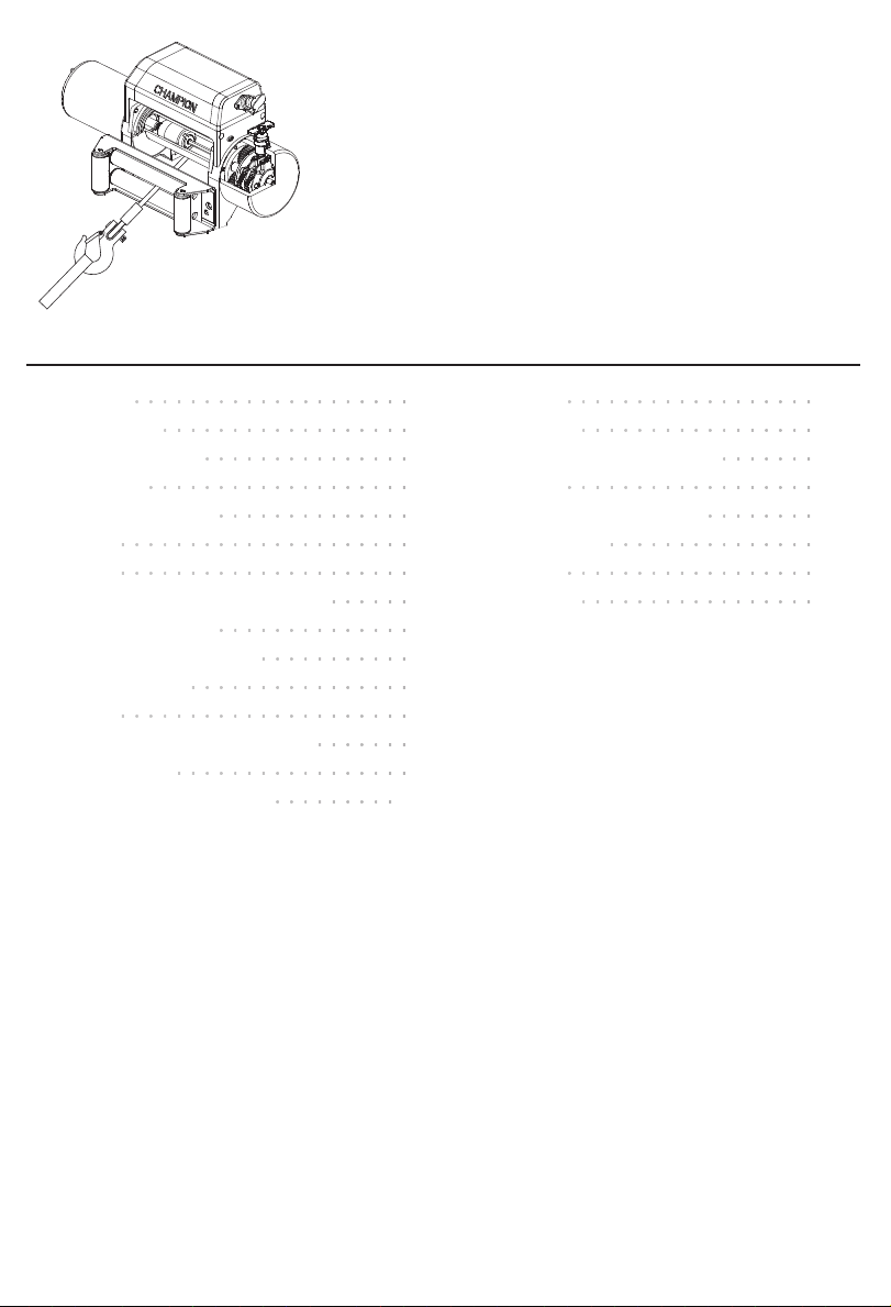
TABLE OF CONTENTS
CHAMPION
C
H
A
M
P
I
O
N
CHAMPION
OUT IN
POWER
100229
10000 lb. (4536 kg)
WINCH KIT
Introduction . ................... 1
Introduction . ................. 1
Manual Conventions ............... 2
Safety Rules ................... 3
Controls and Features .............. 5
Winch ..................... 5
Assembly ..................... 6
Assembling and wiring the Winch . ..... 6
Install the Antenna . ............. 6
Testin g Win ch Op e ratio n . .......... 7
Wiring Diagram . ............... 8
Operation ..................... 9
General Tips for Safe Operation . ...... 9
Self Recovery . ................ 9
Winching Techniques A-Z ......... 10
Maintenance .................. 11
Lubrication ................. 11
Cable Assembly Replacement . ...... 11
Specifications . ................. 12
Performance Specifications ........ 12
Parts Diagram ............... 13
Parts List .................. 14
Tro ubl esh oot in g . ................ 15

ENGLISH 10022 9
INTRODUCTION
Introduction
Congratulations on your purchase of a Champion Power Equipment product. Champion Power
Equipment and Champion Engine Technology designs, builds, and supports all of our products to strict
specifications and guidelines. With proper product knowledge, safe use, and regular maintenance, this
product should bring years of satisfying service.
Every effort has been made to ensure the accuracy and completeness of the information in this
manual, and we reserve the right to change, alter and/or improve the product and this document at any
time without prior notice.
Since CPE/CET highly value how our products are designed, manufactured, operated and are serviced,
and also highly value your safety and the safety of others, we would like you to take the time to review
this product manual and other product materials thoroughly and be fully aware and knowledgeable
of the assembly, operation, dangers and maintenance of the product before use. Fully familiarize
yourself, and make sure others who plan on operating the product fully familiarize themselves too, with
the proper safety and operation procedures before each use. Please always exercise common sense
and always error on the side of caution when operating the product to ensure no accidents, property
damage, or injury occurs. We want you to continue to use and be satisfied with your CPE/CET product
for years to come.
Record the model and serial numbers as well as date and place of purchase for future reference. Have
this information available when ordering parts and when making technical or warranty inquiries.
Champion Power Equipment Support
1-877-338-0999
Model Number
100229
Serial Number
Date of Purchase
Purchase Location
1
100229 ENGLISH
MANUAL CONVENTIONS
This manual uses the following symbols to help differentiate between different kinds of information.
The safety symbol is used with a key word to alert you to potential hazards in operating and owning
power equipment.
Follow all safety messages to avoid or reduce the risk of serious injury or death.
DANGER
DANGER indicates an imminently hazardous
situation which, if not avoided, will result in
death or serious injury.
WARNING
WARNING indicates a potentially hazardous
situation which, if not avoided, could result in
death or serious injury.
CAUTION
CAUTION indicates a potentially hazardous
situation which, if not avoided, may result in
minor or moderate injury.
CAUTION
CAUTION used without the safety alert
symbol indicates a potentially hazardous
situation which, if not avoided, may result in
property damage.
NOTE
If you have questions regarding your winch,
we can help. Please call our help line at
1-8 77-3 38- 0999
2
SAFETY RULES
ENGLISH 10022 9
WARNING
Read this manual thoroughly before operating
your winch. Failure to follow instructions could
result in serious injury or death.
WARNING
Do not exceed the rated capacity.
DANGER
Do not use this winch for lifting or moving
people or animals.
DANGER
Keep yourself and others a safe distance to
the side of the cable when under tension.
DANGER
Never step over a cable or near a cable under
load.
WARNING
Do not use the winch to secure or hold a
vehicle for a long period of time. Do not use
the winch to secure a vehicle for transport.
WARNING
Disconnect the remote control and battery
leads when not in use.
WARNING
Avoid “shock loads” by using the control
switch intermittently to take up the slack in
the wire rope. “Shock loads” can far exceed
the rate capacity for the wire rope and drum.
Do not accelerate your vehicle while winching.
Loss of traction can cause a shock load on
the cable.
WARNING
Batteries contain acid and produce explosive
gases.
WARNING
The wire rope may break before the motor
stalls. For heavy loads at or near rated
capacity, use a pulley block/snatch block to
reduce the load on the wire rope.
WARNING
Do not move the vehicle to pull a load
(towing) on the winch cable. This could result
in cable breakage.
WARNING
Pull only on areas of the vehicle as specified
by the vehicle manufacturer.
3
Keep sparks, flames and cigarettes away from
batteries at all times. Wear safety glasses and
protect the eyes at all times. Do not lean over
the batteries during operation.

100229 ENGLISH
SAFETY RULES
WARNING
When re-spooling the cable, ensure that the
cable spools in the under-wind position with
the cable entering the drum from the bottom,
not the top.
To re-spool correctly, and while wearing
gloves, keep a slight load on the cable while
pushing the remote button to draw in the
cable. Walk toward the winch not allowing
the cable to slide through your hands. Do not
let your hands get within 12 in. of the winch
while re-spooling. Turn off the winch and
repeat the procedure until a few feet of cable
are left. Disconnect the remote control and
finish spooling by rotating the drum by hand
with the clutch disengaged. Keep hands clear
of the fairlead and drum while the winch is
under power .
WARNING
Do not use as a hoist. Do not use for overhead
lifting.
CAUTION
Use gloves to protect hands when handling
the cable. Never let the cable slide through
your hands.
CAUTION
Duration of winching pulls should be kept as
short as possible.
If the motor becomes uncomfortably hot to
the touch, stop winching immediately and let
it cool down for a few minutes. Do not pull for
more than one minute at or near the rated load.
CAUTION
If the motor stalls, do not maintain power to
the winch.
Electric winches are designed and made for
intermittent use and should not be used in
constant duty applications.
CAUTION
Never release the free-spool clutch when
there is a load on the winch.
CAUTION
Use hook strap when handling the hook for
spooling or unspooling the wire rope.
CAUTION
CAUTION
Do not wrap the cable around any object and
hook it back onto itself.
CAUTION
Apply blocks to the wheels of the vehicle
when on an incline.
DO NOT Mix Old and New batteries
DO NOT Mix Alkaline, Standard, or
Rechargeable Bat teries
4

ENGLISH 10022 9
CONTROLS AND FEATURES
Read this owner’s manual before operating your winch. Familiarize yourself with the location and
function of the controls and features. Save this manual for future reference.
Winch
13
14
10
1
2
3
12
11
CHAMPION
4
6
N
O
I
P
M
A
H
C
5
(1) Motor – 3.6 HP (2.7 kW) 12V D C motor provides
power to the planetary gear mechanism.
(2) Winch Drum – The winch drum is the cylinder
on which the wire rope is stored. It can feed or
wind the rope depending on the remote winch
switch.
(3) Roller Fairle ad – When using the winch at an
angle the roller fairlead acts to guide the wire
rope onto the drum and minimizes damage to
the wire rope from abrasion on the winch mount
or bumper.
(4) Wire Rope – 3 /8 in. x 85 ft. (9.2 mm x 26 m)
galvanized aircraf t cable designed specifically
for load capacity of 10000 lb. (4536 kg)
(5) Strap – Used to assist cable feed.
(6) Clevis Hook – Provides a means for connecting
the looped ends of cable s to an anchor.
(7) Antenna – Receives wireless signal from wireless
remote control from within a
50 ft. radius.
(8) Wireless Remote Control – Activate the wireless
system by pressing and holding the POWER
button on the wireless remote for 3 seconds.
8
OUT IN
7
POWER
CHAMPION
9
(9) Remote Switch – Dual switches for powering the
rope in or out of your winch drum.
(10) Winch cover
(11) Planetary Gear System – The reduction gears
conver t the winch motor p ower into extreme
pulling force s. This system allows high torque
while maintaining compact size and light weight.
(12) Free Spooling Clutch – The clutch allows the
operator to manually disengage (“Out”) the
spooling drum from the gear train, free spool.
Engaging the clutch (“In”) locks the winch into
the gear system.
(13) Solenoid – Power from the vehicle battery flows
through the weather sealed solenoid switch
before being directed to the winch motor.
(14) Braking System – Braking action is automatically
applied to the winch drum by a separate
mechanical brake when the winch motor is
stopped and there is a load on the wire rope.
5

100229 ENGLISH
ASSEMBLY
This CPE 10000 lb. (4536 kg) winch is designed
with a bolt pattern that is standard in this class
of winch. Many winch mounting kits are available
that utilize this bolt pattern for the most popular
trucks and Sport Utility Vehicles. If you cannot
find a kit locally, contact CPE and we will provide
you with the name of a dealer near you.
CAUTION
Mounting bolts must be SAE grade 5 or better
and torque to 34 ft. lbs.
Assembling and wiring the Winch
1. Insert 2 M10x35 hexagon head bolts to the
mounting channel hole and attach the roller
fairlead to the mounting channel with the
2 flat washers, lock washers and nuts M10
provided.
2. Disengage the clutch by moving the cam ring
to the “Out” position. Release the wire rope
and pull through the slot in the front of the
channel.
3. Attach the clevis hook and hand strap.
4. Connect the battery leads. FOR WINCH TO
FUNCTION PROPERLY: Connect the red
(positive) lead to the positive (+) terminal
of the vehicle’s 12 volt battery. Connect
the black (negative) lead to the negative (–)
terminal of the vehicle’s 12 volt battery. Do
NOT tighten fasteners at this time.
5. Insert the male quick connect into the female
quick connect to complete the wiring.
Assembling and wiring the Winch Cont’d.
CAUTION
NEVER route electrical cables across any
sharp edges, through and /or near moving
parts, or near parts that may become hot.
CAUTION
Battery cables should not be drawn taut.
Leave some slack for cable movement.
Install the Antenna
1. Determine the mounting location.
2. If mounting on a flat surface, mark and drill
a minimum of two (2) mounting holes, one
on each side of the antenna. Loosely attach
the antenna using the supplied bolts and lock
nuts. Do NOT tighten fasteners at this time.
3. If mounting on a frame tube, loosely attach
using the supplied cable ties.
4. Connect the black ground wire with the ring
to the negative (–) terminal of the vehicle’s
12 volt batter y.
6

ENGLISH 10022 9
ASSEMBLY
Assembling and wiring the Winch Cont’d. Assembling and wiring the Winch Cont’d.
Test Winch Operation
1. Make sure there are no exposed terminals
or wiring, and wiring to all components is
correct, all loose wires should be secured.
2. Turn the Master Control Switch to the ON
position.
– Master Control On/ Off Switch:
1) LED lit when switched ON ;
2) Amps will read zero when switched off.
3. Attach the handle remote lead to the winch
and test for proper operation.
4. Check for proper drum rotation. Turn the
clutch handle to the “out” position (free
spooling). Pull about 2 ft. of cable from the
drum, then turn the clutch knob to the “In”
position to engage the gears. Press the cable
out button on the power switch. If the drum
is turning and releasing more cable then
your connections are accurate. If the drum
is turning and collecting more cable then
reverse the leads on the motor. Repeat and
check rotation.
5. To test wireless system:
1) Disconnect the handle remote, attach the
wireless receiver lead to the winch and test
for proper operation.
2) Activate the system by pressing and
holding the POWER button on the wireless
remote for 3 seconds. This transfers control
of the winch to the wireless control system.
A red indicator light on the wireless remote
turns on when the system is active and ready
to use.
CAUTION
Led Indicator Light
Steady Red: System active and ready to use.
Flashing Red: Winch powering in or out.
3) Verify that the winch spools the rope in
and out properly by pressing the buttons on
the wireless remote. The wire rope should
spool in and out in the direction indicated on
the remote.
4) Deactivate the system by pressing the
POWER button on the wireless remote and
holding for 3 seconds, until red light turns off
or after 2 minutes of idle time, the wireless
system automatically de-activates.
CAUTION
Turn the Master Control Switch to the OFF
position if you leave the operator position for
any reas on.
7

100229 ENGLISH
Wiring Diagram
ASSEMBLY
N
O
I
P
M
A
H
C
POWER
OUT IN
CHAMPION
BLACK
+
_
RED
Battery
—
BLACK
RED
BLACK
O
8

OPERATION
ENGLISH 10022 9
General Tips for Safe Operation
Your 100229 winch is rated at a 10000 lb.
(4536 kg) capacity in first layer (max) when
spooling the first rope layer on the drum. Overloads
can damage the winch, motor and/or wire rope.
For loads over 50% we recommend the use of the
pulley block/snatch block (not included) to double
the wire rope line. This will aid in two ways:
(a) reduce the number or rope layers on the drum,
as well as,
(b) reduce the load on the wire rope by as much
as 50%.
When doubling the line back to the vehicle,
attach to the tow hook, frame or other load bearing
part. The vehicle engine should be kept running
during operation of the winch to minimize battery
drain and maximize power and speed of the winch.
If the winch is used for a considerable time with
the engine off the battery may be drained and too
weak to restart the engine.
Get to know your winch before you actually need to
use it. We recommend that you set up a few test
runs to familiarize yourself with rigging techniques,
the sounds your winch makes under various loads,
the way the cable spools on the drum, etc.
Inspect the wire rope and equipment before each
use. A frayed or damaged rope shall be replaced
immediately. Use only manufacturer’s identical
replacement rope with the exact specifications.
Inspect the winch installation and bolts to ensure
that all bolts are tight before each operation. Store
the remote control inside your vehicle in a place
that it will not be damaged.
Any winch that appears to be damaged in any way,
is found to be worn, or operates abnormally MUST
BE REMOVED FROM SERVICE UNTIL REPAIRED.
It is recommended that the necessary repairs
be made by a manufacturer’s authorized repair
facility.
Pull only on areas of the vehicle as specified by
the vehicle manufacturer. Only attachments and/
or adapters supplied by the manufacturer are to
be used.
9
Self Recovery
Locate a suitable anchor such as a strong tree trunk
or boulder. Always use a sling (not included) as an
anchor point.
A roller fairlead (included) will help guide the wire
rope and to reduce binding on short side pulls. Do
not winch from an acute angle as the wire rope will
pile up on one side of the drum causing damage to
wire rope and the winch.
RIGHT WRONG
Short pulls from an angle can be used to straighten
the vehicle. Long pulls should be done with the
wire rope at a 90° angle to the winch/vehicle. When
pulling a heavy load, place a blanket or jacket over
the wire rope 5-6 ft. (1.5-1.8 m) from the hook.
In the event of a broken cable it will dampen
the snap back. For additional protection open
the hood of the vehicle. For pulls over 50%,
we recommend the use of the snatch block /pulley
block to double line the wire rope.
SINGLE LINE DOUBLE LINE
This reduces the load on the winch and the strain
on the rope by approximately 50%.

100229 ENGLISH
OPERATION
Winching Techniques A-Z
(a) Take time to a s sess you r s itu ation and plan
your pull.
(b) Put on gloves to protect your hands.
(c) Disengage the clutch to allow free- spooling
and also save battery power.
(d) Attach the hook strap to the clevis hook.
(e) Pull out the wire rope to your desired anchor
point using the hook strap.
(f) Secure the clevis hook to the anchor point:
Sling, chain or snatch block. Do not attach
the hook back onto the wire rope.
(g) Engage the clutch.
(h) Connect the remote control to the winch. If
you are going to control the winch from inside
your vehicle then pass the remote through an
open window to avoid the wires being pinched
in the door.
(i) Start your engine to ensure power is being
replenished to the battery.
(j) Power in the wire rope guiding the wire under
tension to draw up the slack in the wire. Once
the wire is under tension, stand clear. Never
step over the wire rope.
(k) Double check your anchors and make sure all
connections are secure.
(l) Inspect the wire rope. Make sure there are at
least 5 wraps of wire rope around the winch
drum.
(m) Drape a blanket or jacket over the wire rope
approximately 5-6 ft. (1.5-1.8 m) from the
hook. Open the hood for added protection.
(n) Clear the area. Make sure all spectators stand
clear and that no one is directly in front or
behind the vehicle or anchor point.
(o) Begin winching. Be sure that the wire rope
is winding evenly and tightly around the
drum. The vehicle that is being winched can
be slowly driven to add assistance to the
winching process. Avoid shock loads; keep
the wire rope under tension.
Winching Techniques A-Z Cont’d.
(p) The vehicle to be winched should be placed
in neutral and the emergency brake released.
Only release the brake pedal when under full
tension. Avoid shock loads to the winch. This
can damage the winch, rope and vehicle.
(q) The winch is meant for intermittent use.
Under full load with a single line rig do not
power in for more than a minute without
letting the motor cool down for a few minutes
and then resume the winching operation.
(r) The winching operation is complete once the
vehicle is on stable ground and is able to
drive under its own power.
(s) Secure the vehicle. Be sure to set the brakes
and place the vehicle in park.
(t) Release the tension on the wire rope. The
winch is not meant to hold the vehicle for
long periods of time.
(u) Disconnect the wire rope from the anchor.
(v) Rewind the wire rope. Make sure that any wire
already on the drum has spooled tightly and
neatly. If not, draw out the wire and re-spool
from the point where the rope is tight.
(w) Keep your hands clear of the winch drum and
fairlead as the wire rope is being drawn in.
(x) Secure the hook and hook strap.
(y) Disconnect the remote control and store in a
clean, dry place.
(z) Clean and inspect connections and mounting
hardware for next winching operation.
10

MAINTENANCE
ENGLISH 10022 9
The owner/operator is responsible for all periodic
maintenance.
WARNING
Never operate a damaged or defective winch.
WARNING
Improper maintenance will void your warranty.
Complete all scheduled maintenance in a timely
manner. Correct any issue before operating the
winch.
NOTE
For ser vice or parts assistance, contact our
help line at 1-877-33 8-0 999
Lubrication
All moving parts within the electric winch having
been lubricated using high temperature lithium
grease at the factory. No internal lubrication is
required. Lubricate cable assembly periodically
using a light penetrating oil.
Cable Assembly Replacement
It is recommended that any modifications be
performed by a manufacturer’s authorized repair
facility, and that only manufacturer-supplied parts
be used.
1. Move the clutch to the “Out” position.
2. Extend cable assembly to its full length. Note
how the existing cable is connected to the
inside of the drum.
3. Remove old cable assembly and attach new
one.
4. Retract cable assembly onto drum being
careful not to allow kinking.
11

100229 ENGLISH
SPECIFICATIONS
Performance Specifications
– Rated Pull ..................................... 10000 lb. (4536 kg)
– Gear Reduction Ratio ....................................... 216:1
– Motor .......................... Series Wound Motor 3.6 HP/2.7 kW (12V DC)
– Duty Cycle ..................................... Intermittent Use Only
– Drum Size . ................... 2.5 in. (D) x 8.8 in. (L) [63 mm (D) x 224.5 mm (L)]
– Cable ......................... 3/8 in. (D) x 85 ft. (L) [9.2 mm (D) x 26 m (L)]
– Gross Weight ..................................... 95.5 lb. (43.3 kg)
– Net Weight ........................................ 90.4 lb. (41 kg)
– Height . ........................................ 10.5 in. (26.7 cm)
– Width .......................................... 5.6 in. (14.2 cm)
– Length ........................................ 21.9 in. (55.5 cm)
– Bolt Pattern. . . . . . . . . . . . . . . . . . . . . . . . . . . . 10 in. x 4.5 in. (25.4 c m x 11.4 c m)
Line Speed and Motor Current (First Layer)
Line Pull
Line Speed (12V DC)
Max Current A 115 175 220 280 320 400
Run Time* Minutes 1 1 1 1 1 1
Cooling Time** Minutes 5 5 5 5 5 5
* If the mo tor be come s unco mfor tably hot to the tou ch, sto p winchin g immediately and let it coo l down for 5 minutes . Do n ot
pull for more than one minute at or near the rated loa d.
** Elect ric winches a re designed and ma de for intermi ttent use and should not b e use d in constan t duty applications .
LB 0 2000 4000 6000 8000 1000 0
KG 0 907 1814 2722 3629 4536
FPM 15.7 9.8 7. 2 5.9 4.9 3.9
MPM 4.8 3.0 2.2 1.8 1.5 1.2
Line Pull and Cable Capacity Per Layer
Line of Cable 1 2 3 4
Rated Line Pull
Cable Capacity
– Use double line and sna tch blo ck for pulling lo ads over 50 %.
LB 10000 8000 6600 5600
KG 4536 3629 2994 2540
FT 18 39.4 64 85
M 5.5 12 19.5 26
12

SPECIFICATIONS
Parts Diagram
ENGLISH 10022 9
13
C
H
A
M
P
I
O
N

100229 ENGLISH
Parts List
# Part number Description
P1010100
1
P1010200
2
P1010300-N
3
P1010400 Cable Assenbly 1
4
P1011001-B Switch Assembly - Black 1
5
P1011002A-BFUp-setting Solenoid
6
P1011003A-BFMotor/End Bearing
7
P1011021 Gear Housing A 1
8
P1011400 Brake Assembly 1
9
P1011500-BF
10
P1011005-
11
N-BF
P1011022 Pan Head Screw M5 x 15 1
12
P1011023 Washer Ø5 1
13
P1011024 Clutch Handle 1
14
P1011025 Clutch Seat 1
15
P1011026 Seal Ring Ø20 x 1.8 1
16
P1011027 Spring 1
17
P1011028 Clutch Pin 1
18
P1011029 Set Screw M4 x 8 1
19
P1011010
20
P1011030 Gear Housing B 1
21
P1011012 Bushing 1
22
P1011013 Thrust Washer 1
23
P1011014 Motor/End Bearing Seal 2
24
P1011015-
25
N-BF
P1011016 Lock Washer Ø6 8
26
Gear Carrier Assembly Input
Gear Carrier Assembly Intermediate
Gear Carrier Assembly Output
Assembly - Black Flat
Assembly - Black Flat
Drum A ssembly - Black
Flat
Gear Housing End Cover Black Flat
Gear Housing End Cover
Seal
End Bearing - Black Flat 1
Qty
# Part number Description
P1011017
27
1
P1011018 Thrust Disc 2
28
1
1
1
1
1
1
1
P1010008 Bushing -Drum 1
29
P1010012 Cap Screw M6 x 6 1
30
P1010013 Lock Nut M8 4
31
P1010014
32
P1010015 Motor/Drum Bushing 1
33
810024 Lock Nut M10 6
34
81002 3 Flat Washer Ø10 6
35
81002 2 Lock Washer Ø10 6
36
810021
37
810025-N Te rm inal Pro te ct or 3
38
41002 2 Yello w Str ap 1
39
18029-3 Wireless Receiver 1
40
18029-1 Wireless Remote 1
41
811000 -B F Roller Fairlead - Black Flat 1
42
C180 08
43
C10038 3/8 in. Clevis Hook 1
44
810033 Motor C oupling 1
45
P1011033A Hexagonal Shaft I 1
46
P1011034A Hexagonal Shaft II 1
47
P1011037 Sun Gear, Input 1
48
P1011039 Seal Ø10 x Ø1.8 1
49
18035 Winch Cover 1
50
18029- 015 Lock Nut M4 4
51
18029- 016 Flat Washer Ø4 4
52
18029- 017 Lock Washer Ø4 4
53
18029- 018 Hexagon Head Bolt M4 x 20 4
54
Hexagon Socket Head
Screw M6 x 20
Hexagon Socket Head
Screw M8 x 25
Hexagon Head Bolt
M10 x 35
6 ft. C able with Quick
Connect
Qty
8
4
6
1
14

TROUBLESHOOTING
Problem Cause Solution
Switch as sembly not connected
properly
Loose battery cable connections Tighten nuts on all cable connections.
Contactor malfunctioning
Motor does not turn on
Defective switch assembly Replace switch assembly.
Defective motor
Water has entered motor
Motor runs but cable
drum does not turn
Motor runs slowly or
without normal power
Motor overheating Winch running time too long Allow winch to cool down periodically.
Motor runs in one
direction only
Clutch (cam ring) not engaged
Insufficient current or voltage
Loose or corroded battery cable
connections.
Defective or stuck contactor
Defective switch assembly Replace switch assembly.
Inser t switch assembly all the way into the connector.
Tap c ont ac tor t o lo ose n c on tac ts. A pply 12 v ol ts to
coil terminals directly. A clicking indicates proper
activation.
Check for voltage at armature port with switch
pressed. If voltage is present, replace motor.
Allow to drain and dr y. Run in short bursts without
load until completely dry.
Move cam ring to the "In" position. If problem
persists, a qualified technician needs to check and
repair.
The battery is weak, recharge. Run winch with vehicle
motor running (battery should have a strong charge)
Clean, tighten, or replace.
Tap c ont ac tor t o lo ose n c on tac ts.
Repair or replace contactor.
ENGLISH 10022 9
For further technical support:
Tec hn ical Ser vice
Mon – Fri 8 :30 AM – 5:00 PM (PST/PDT)
Toll Fr ee: 1- 87 7-33 8 - 0999
tech@ championpowerequipment.com
15

WARRANTY
CHAMPION POWER EQUIPMENT
2 YEAR LIMITED WARR ANTY
Warranty Qualifications
To registe r your p roduct for war ranty and FREE lif etime call
center technical support please visit:
https:/ /www.championpowerequipment.com/ re gister
To complete regist ration y ou will nee d to include a copy of
the purc hase re ceipt as proof o f original purchas e. Pro of of
purchase is required for warranty service. Please register
within ten (10) days from date of purchase.
Repair/Replacement Warranty
CPE warrants to the or iginal purchaser t hat the m echanica l
and electrical c ompone nts will b e free of defect s in
material and wor kmanship for a pe riod of t wo yea rs (pa rts
and labor) from the origin al date of purchas e and 180
days (p arts and labo r) for co mmercial and indus trial us e.
Transpor tation charge s on pr oduct submitted for rep air or
replacement und er this wa rrant y are th e sole responsibility
of the pu rchase r. This war ranty o nly applie s to the o riginal
purchaser and is not transferable.
Do Not Return The Unit To The Place Of
Purchase
Conta ct CPE’s Technical Se rvice a nd CPE will trouble shoot
any iss ue via pho ne or e -mail. If t he probl em is not
corrected by this method, CPE will, at its option, authorize
evaluati on, repai r or repl acement of the de fective part o r
component at a CPE Ser vice C enter. CPE will provid e you
with a ca se numb er for w arrant y ser vice. P lease keep it
for futu re reference. Re pairs o r replac ements without p rior
authorization, or at an u nauthori zed repair facilit y, will not
be covered by this warranty.
Other Exclusions
This warranty excludes:
– Cosmetic defects such as paint, decals, etc.
– Wear items such as winch cable , etc.
– Accessory parts such as storage covers.
– Failures due to ac ts of Go d and other force majeur e
events beyond the manufacturer’s control.
– Probl ems caus ed by p arts that are not orig inal
Champion Power Equipment parts.
Limits of Implied Warranty and
Consequential Damage
Champio n Power Equipment di sclaims any obligation to
cover a ny loss of time, u se of this produc t, freig ht, or any
incident al or con sequential claim by a nyone fr om using
this pro duct. THI S WARRAN TY IS IN LIEU OF AL L OTHER
WARRAN TIES, EX PRESS O R IMPLIED, IN CLUDING
WARRAN TIES OF MERCHANTABILITY OR FITNESS FOR A
PARTICUL AR PURPOSE.
A unit provided a s an excha nge will be subject t o the
warra nty of t he origin al unit. Th e lengt h of the w arrant y
governin g the exchanged unit will remain calculate d by
reference to the purchase date of the original unit.
This warranty gives y ou cer tain leg al right s which may
change f rom st ate to st ate or p rovince to provin ce. Your
state or prov ince may also have other rights you may be
entitled to that are not listed within this warranty.
Contact Information
Address
Champion Power Equipment, Inc.
Customer Service
12039 Smith Ave.
Santa Fe Springs, CA 90670 USA
www.championpowerequipment.com
Warranty Exclusions
This warranty does not cove r the following rep airs and
equipment:
Normal Wear
Products with mechanical and electrical components need
periodic parts and service to perform well. This warranty does
not cover repair when normal use has exhausted the life of a
part or the equipment as a whole.
Installation, Use and Maintenance
This warranty will not ap ply to pa rts an d/or labo r if the
product is dee med to ha ve been misused , neglected,
involved in an accident, abu sed, lo aded be yond the
product’s limits , modifi ed, inst alled impr operly or
connec ted inco rrectly to any ele ctrical compon ent. No rmal
maintenan ce is not covere d by this w arranty and is not
require d to be p erfor med at a facility o r by a pe rson
authorized by CPE.
Customer Service
Mon – Fri 8:30 AM – 5:00 PM (PST/PDT)
Toll Fr ee: 1- 877- 338 -09 99
info@ champi onpowerequipment .com
Fax no. : 1-562-2 36-9 429
Technical Service
Mon – Fri 8:30 AM – 5:00 PM (PST/PDT)
Toll Fr ee: 1- 877- 338 -09 99
tech@ championpowere quipment.com
24/ 7 Tech Suppor t: 1-5 62-20 4-1188
 Loading...