

Page 1
Installation/Operation with Service Replacement Parts
Single Tank Dual Rinse
44" Model 44DR
E-series Rack Conveyor
Single Tank Dual Rinse
44" with 22" Prewash
Model 66DRPW
Dishwashers
Models
Single Tank Dual Rinse
44DR
66DRPW
70DRFFPW
80DRHDPW
(with swing-out doors)
Two Tank
64
86PW
90FFPW
100HDPW
www.championindustries.com
3765 Champion Boulevard
Winston-Salem, NC 27105
(336) 661-1556 Fax: (336) 661-1660
Toll-free: 1 (800) 858-4477
Two Tank 64"
Wash and Power Rinse
Model 64
Issue Date: 7.14.15
Manual P/N 115328 rev. A
For machines beginning with S/N RE13077060 and above
2674 N. Service Road, Jordan Station
Ontario, Canada L0R 1S0
(905) 562-4195 Fax: (905) 562-4618
Toll-free: 1 (800) 263-5798
54DR
76DRPW
80DRFFPW
90DRHDPW
84
106PW
110FFPW
120HDPW
Printed in USA
Page 2
For future reference, record your dishwasher information in the box below.
Model Number__________________________ Serial Number_______________________
Voltage________________Hertz_____________ Phase__________________
Champion Service Agent __________________________________ Tel:______________________
Champion Parts Distributor _________________________________ Tel:______________________
National Service Department
In Canada: In the USA:
Toll-free: 1 (800) 263-5798 Toll-free: 1 (800) 858-4477
Tel: (905) 562-4195 Tel: (336) 661-1556
Fax: (905) 562-4618 Fax: (336) 661-1660
email: service@moyerdiebellimited.com email: service@championindustries.com
ATTENTION:
The dishwasher model number,
serial number, voltage, hertz and phase
are needed to identify your machine and to
answer questions.
Please have this information on-hand
if you call for service assistance.
For all models:
The data plate mounts to one
side of the top-mounted control
cabinet.
The Canadian Green Building Council, respectively, and are used by permission. The logos signify only that Champion Industries,
The USGBC and the CaGBC Member Logos are trademarks owned by the U.S. Green Building Council and
Inc. is a USGBC member and a CaGBC member; USGBC and CaGBC do not review,
certify nor endorse the products or services offered by its members.
COPYRIGHT © 2015 All rights reserved Printed in the USA
Page 3

REGISTER YOUR PRODUCT ONLINE
Make sure you are connected to the internet then enter an address below:
In the U.S.A.
http://www.championindustries.com/register
In Canada
http://www.championindustries.com/canada/register
Page 4
PRODUCT REGISTRATION
IMPORTANT IMPORTANT
BY FAX
COMPLETE THIS FORM AND FAX TO:
(336) 661-1660 in the USA
1 (800) 204-0109 in Canada
PRODUCT REGISTRATION CARD
Model
Date of Installation:
Company Name:
Address:
Telephone #: ( ) ---
(Street)
Serial #
State
or Province
Zip or
Postal Code
Contact:
Installation Company:
Address:
Telephone #:
Contact:
FAILURE TO REGISTER YOUR PRODUCT MAY VOID YOUR WARRANTY
Page 5

Revision History
Revision History
A revision might be a part number change, new instructions, or information that was
not available at print time. We reserve the right to make changes to this manual without
notice and without incurring any liability by making the changes. Dishwasher owners
may request a revised manual, at no charge, by calling 1 (800) 858-4477 in the USA
or 1 (800) 263-5798 in Canada.
Revision Revised Serial Number Description
Date Pages Effectivity
9.11.13 All RE13077060 Released First Edition
7.14.15 60-63, 124-129 RE150607977 Revised images and Parts List for
Doors and Screens
7.14.15 All --- Reviewed and Revised Manual
i
Page 6

Limited Warranty
LIMITED WARRANTY
Champion Industries Inc. (herein referred to as Champion), 3765 Champion Blvd., Winston-Salem, North Carolina 27105, and
P.O. Box 301, 2674 N. Service Road, Jordan Station, Canada, L0R 1S0, warrants machines, and parts, as set out below.
Warranty of Machines: Champion warrants all new machines of its manufacture bearing the name "Champion" and
installed within the United States and Canada to be free from defects in material and workmanship for a period of one (1) year
after the date of installation or fifteen (15) months after the date of shipment by Champion, whichever occurs first. [See below
for special provisions relating to glasswashers.] Warranty registration must be returned to Champion within ten (10) days after
installation either online on the Champion Industries website (http://www.championindustries.com/register) in the USA or
http://www.championindustries.com/canada/register in Canada or by fax on the form provided at the front of this manual. If
warranty registration is not returned to Champion within such period, the warranty will expire after one year from the date of
shipment. Champion will not assume any responsibility for extra costs for installation in any area where there are jurisdictional
problems with local trades or unions. If a defect in workmanship or material is found to exist within the warranty period,
Champion, at its election, will either repair or replace the defective machine or accept return of the machine for full credit;
provided; however, as to glasswashers, Champion's obligation with respect to labor associated with any repairs shall end (a)
120 days after shipment, or (b) 90 days after installation, whichever occurs first. In the event that Champion elects to repair, the
labor and work to be performed in connection with the warranty shall be done during regular working hours by a Champion
authorized service technician. Defective parts become the property of Champion. Use of replacement parts not authorized by
Champion will relieve Champion of all further liability in connection with its warranty. In no event will Champion's warranty
obligation exceed Champion's charge for the machine. The following are not covered by Champion's warranty:
a. Lighting of gas pilots or burners.
b. Cleaning of gas lines.
c. Replacement of fuses or resetting of overload breakers.
d. Adjustment of thermostats.
e. Adjustment of clutches.
f. Opening or closing of utility supply valves or switching of electrical supply current.
g. Cleaning of valves, strainers, screens, nozzles, or spray pipes.
h. Performance of regular maintenance and cleaning as outlined in operator’s guide.
i. Damages resulting from water conditions, accidents, alterations, improper use, abuse,
tampering, improper installation, or failure to follow maintenance and operation procedures.
j. Wear on Pulper cutter blocks, pulse vanes, and auger brush.
Examples of the defects not covered by warranty include, but are not limited to: (1) Damage to the exterior or interior finish
as a result of the above, (2) Use with utility service other than that designated on the rating plate, (3) Improper connection to
utility service, (4) Inadequate or excessive water pressure, (5) Corrosion from chemicals dispensed in excess of recommended
concentrations, (6) Failure of electrical components due to connection of chemical dispensing equipment installed by others, (7)
Leaks or damage resulting from such leaks caused by the installer, including those at machine table connections or by connection
of chemical dispensing equipment installed by others, (8) Failure to comply with local building codes, (9) Damage caused by
labor dispute.
Warranty of Parts: Champion warrants all new machine parts produced or authorized by Champion to be free
from defects in material and workmanship for a period of 90 days from date of invoice. If any defect in
material and workmanship is found to exist within the warranty period Champion will replace the defective
part without charge.
DISCLAIMER OF WARRANTIES AND LIMITATIONS OF LIABILITY. CHAMPION'S WARRANTY IS ONLY
TO THE EXTENT REFLECTED ABOVE. CHAMPION MAKES NO OTHER WARRANTIES, EXPRESS OR
IMPLIED, INCLUDING, BUT NOT LIMITED, TO ANY WARRANTY OF MERCHANTABILITY, OR FITNESS
OF PURPOSE. CHAMPION SHALL NOT BE LIABLE FOR INCIDENTAL OR CONSEQUENTIAL DAMAGES.
THE REMEDIES SET OUT ABOVE ARE THE EXCLUSIVE REMEDIES FOR ANY DEFECTS FOUND TO EXIST
IN CHAMPION DISHWASHING MACHINES AND CHAMPION PARTS, AND ALL OTHER REMEDIES
ARE EXCLUDED, INCLUDING ANY LIABILITY FOR INCIDENTALS OR CONSEQUENTIAL DAMAGES.
Champion does not authorize any other person, including persons who deal in Champion dishwashing machines to change this warranty or
create any other obligation in connection with Champion Dishwashing Machines.
ii
Page 7

Table of Contents
Table of Contents
E-series Rack Conveyor Dishwashers
Revision History ........................................................................................................................... i
Limited Warranty ......................................................................................................................... ii
Model Descriptions....................................................................................................................... iv
Installation .................................................................................... 1
Installation Codes, Warranty Registration, Receiving ....................................................... 1
Table Connections ....................................................................................................... 2
Utilities, Hot and Cold Water Connections ..................................................................... 3
Drain Connections, Steam Supply and Condensate Connections ....................................... 4
Ventilation Guidelines
Electrical Connections .................................................................................................. 5
Optional Table Limit Switch .......................................................................................... 7
Chemical Connections, Vent Fan Signal Connections ....................................................... 8
Machine Running and Table Limit Switch Signal Connections ............................................ 9
Curtain Locations ........................................................................................................ 10
Hot Water Coil Tank Heat, Air Purging Instructions .......................................................... 11
Door Safety Switches ................................................................................................... 13
Removing and Installing Spray Arms and Scrap Screens .................................................. 14
Installation Checklist .................................................................................................... 18
.................................................................................................. 4
Operation .....................................................................................19
Operation .................................................................................................................. 19
Door Safety Switches ................................................................................................... 20
Scrap Screens............................................................................................................. 22
Cleaning and Maintenance .......................................................................................... 23
E-Rack Digital Temperature Display Meters (Operation and Calibration) ............................. 26
Troubleshooting .......................................................................................................... 30
Service Replacement Parts .......................................................... 31
Electrical Schematics ....................................................................147
Control Circuit Board Diagnostics ...............................................157
iii
Page 8

Model Descriptions
Model Descriptions
Champion's single tank and two tank rack conveyor dishwashers are fully automatic. Standard
equipment includes 1HP prewash, 2HP wash and 2HP power rinse pumps.
The conveyor drive is a 1/6 HP motor. All models are available in right-to-left (R-L) or
left-to-right (L-R) direction.
Model Numbers
Single Tank - Basic (dual rinse)....................................... 44DR, 54DR
Single Tank with 22" Prewash (dual rinse) ....................... 66DRPW, 76DRPW
Single Tank with 36" Prewash ....................................... 80DRHDPW, 90DRHDPW
Single Tank with 26" Front Feed Prewash ....................... 70DRFFPW, 80DRFFPW
Dual-Rinse (DR) models feature a recirculating rinse that conserves energy.
The 44 DR and 54 DR basic models are high temperature 180°F/80°C hot final rinse
water sanitizing dishwashers. Prewash options are available in 22", 36", and
26" front feed. Built-in stainless steel electric booster heaters in 40°F/22°C and
70°F/39°C rise are available and steam booster heaters in 40°F/22°C and 70°F/39°C rise.
Two Tank - Basic .......................................................... 64, 84
Two Tank with 22" Prewash ........................................... 86PW, 106PW
Two Tank with 36" Prewash ........................................... 100HDPW, 120HDPW
Two Tank with 26" Front Feed Prewash ........................... 90FFPW, 110 FFPW
The 64, and 84 basic models are high temperature 180°F/80°C hot water final rinse
sanitizing models. Prewash options are available in 22", 36", and 26" front feed.
Built-in stainless steel electric booster heaters in 40°F/22°C and 70°F/39°C rise are
available and steam booster heaters in 40°F/22°C and 70°F/39°C rise.
All rack conveyor dishwasher models are covered by a 1-year parts and labor limited
warranty.
! ATTENTION !
The installation, and initial start-up of your dishwasher must be performed by qualified
electricians, plumbers, and authorized service technicians trained in commercial
dishwashers.
Defects and repairs caused by unauthorized installers will not be covered by the
limited dishwasher warranty.
iv
Page 9

Installation
Installation Codes
The installation of the dishwasher must comply with all local electrical, plumbing, health and
safety codes or in the absence of local codes, installed in accordance with the applicable
requirements in the National Electrical Code, ANSI/NFPA 70 (latest edition), CAN/CSA B149.1
and the Canadian Electrical Code (CEC), Part 1, CSA C22.1 (latest edition); and the Standard
for Ventilation Control and Fire Protection of Commercial Cooking Operations, NFPA 96.
Warranty Registration
Warranty registration must be submitted to Champion within ten (10) days after installation either
online on the Champion Industries website (http://www.championindustries.com/register) in the
USA or http://www.championindustries.com/canada/register in Canada or by fax on the form
provided at the front of this manual. If warranty registration is not returned to Champion within
such period, the warranty will expire after one year from the date of shipment.
Receiving
CAUTION:
Be careful when moving or lifting the dishwasher to prevent damaging the dishwasher or the
installation site. Check doorway and passageway clearance before moving the dishwasher.
Remove dishwasher front panels and check under the machine base for obstructions before
moving.
1. Inspect the dishwasher for shipping damage
2. Check the dishwasher interior for curtains, panels and other supplies.
3. Lift the dishwasher off the shipping pallet and move the machine near its permanent location.
4. Leave a minimum of 6" between walls and the rear of the dishwasher.
5. Level the dishwasher side-to-side and front-to-back using a bubble level.
The dishwasher legs are adjusted by screwing them in or out.
6. Do not remove tags attached to the utility connections until the installation is complete.
7. Remove the protective film from the dishwasher exterior.
8. Remove any foreign material from the dishwasher interior.
1
Page 10
Installation
Table Connections
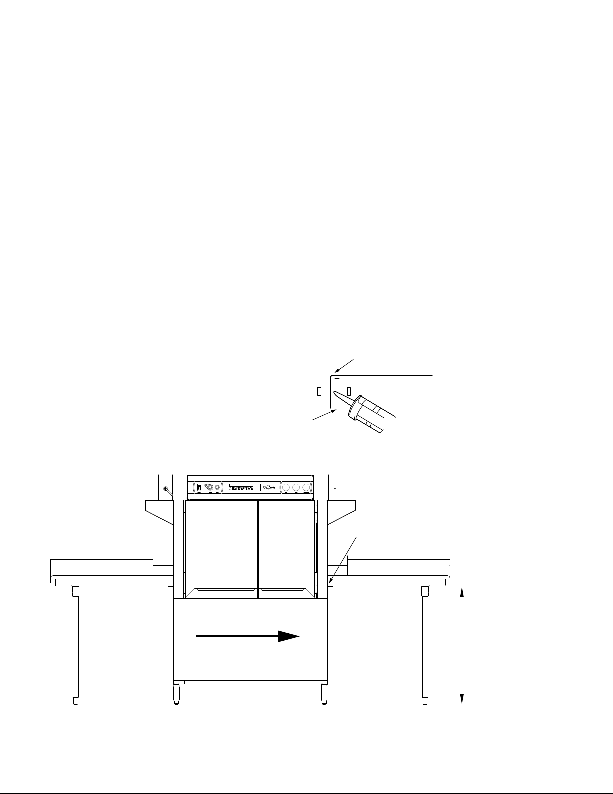
The dishwasher and dish tables must be in their final locations and level before connection. The
recommended table height is 34”/864mm.
1. Slope the load end dish table away from the entrance of the dishwasher to prevent water
from flowing into the dishwasher.
2. Slope the unload end dish table toward from the exit of the dishwasher so that water
flows back into the dishwasher.
3. The dish table flanges should be bolted and sealed to the ends of the dishwasher using a
food-grade silicon sealant as shown in the table connection detail illustration below.
Dishwasher
Table connection detail
Table
Flange
Silicon
Sealant
See the table
connection detail above
2
L-R Direction Shown
Typical table installation
Standard Table
Height
34"
Page 11

Installation
Utilities
Hot Water Connections
NOTE:
Only qualified personnel should make dishwasher plumbing connections. Connections must
meet local plumbing and sanitary codes. Improper installation is not covered be the dishwasher
warranty.
Hot Water Requirements:
1. A water hardness of 3 grains/U.S. gal [51.3 mg/L] or less is recommended.
2. Connect a 3/4" NPT hot water supply line to the line strainer located at the top rear of the
dishwasher.
3. For a dishwasher without a booster heater, the hot water connection must supply a
minimum of 180°F/82°C measured at the dishwasher.
4. For a 40°F/22°C rise booster heater, the hot water connection must supply a minimum of
140°F/60°C measured at the dishwasher.
5. For a 70°F/39°C rise booster heater, the hot water connection must supply a minimum of
110°F/43°C measured at the dishwasher.
6. For a single wash tank hot water coil heated dishwasher, the hot water connection must
supply a minimum of 185°F/85°C measured at the dishwasher.
7. For a two-tank hot water coil heated dishwasher, the hot water connection must supply a
minimum of 195°F/91°C measured at the dishwasher.
8. Install a pressure regulating valve (PRV) before the dishwasher supply connection to
maintain a flowing pressure of 20-25 PSI
9. Install a service shut-off valve in the supply line, as close to the dishwasher as possible.
The size of the valve must be the same size or larger than the supply line.
Cold Water Connections
Cold Water Requirements:
1. A water hardness of 3 grains/U.S. gal [51.3 mg/L] or less is recommended.
2. Connect a 1/2" NPT cold water supply line for a dishwasher equipped with a prewash cold
water tempering option. Connection is located at the top of rear of the dishwasher load end.
3. Connect a 1/2" NPT cold water supply line for dishwashers required to have a drain water
temperature tempering option. Request a drain tempering water kit (P/N 452891).
3
Page 12

Installation
Drain Connections
1. The 1-1/2" drain line was removed and packed inside the dishwasher prior to shipping. Install the drain
line once the dishwasher has been placed in its final location.
2. Connect the 1-1/2" NPT drain line above a drain sink or to a 1-1/2" or larger drain line connection.
3. Observe all local plumbing and sanitary codes when installing.
Steam Supply and Condensate Connections
1. The steam supply line must be a 2" NPT line.
2. Check the steam pressure requirements prior to connecting the steam supply lines. Standard high
steam supply required is 15-30 PSI/103-201 kPa.
3. Low steam supply pressure is 7-14 PSI/48.2-96.5 kPa
4. Connect a steam supply line the same size or larger to the dishwasher at the steam supply strainer
located at the unload end of the dishwasher.
5. Condensate lines must be gravity drain with no back pressure. A condensate lift pump must be
installed if the condensate flow is above the finished floor.
Ventilation Connections
1. DO NOT VENT THE DISHWASHER INTO WALLS, CEILINGS OR ENCLOSED PLACES.
2. Vent stacks with adjustable dampers are supplied with the dishwasher to connect house vent.
3. Connect stainless steel water-tight duct inside the 4" x 16"/ 106mm x 407mm vent stacks
supplied with the dishwasher.
4. A minimum of 6 air changes per hour of kitchen is recommended
Ventilation Guidelines:
Dishwasher without a prewash tank option:
Load end- 200 CFM @ 1/4" SP/ 95 Liters/second
Unload end- 400 CFM @ 1/4" SP/ 189 Liters/second
Dishwasher with a Prewash tank option:
Load end- 150 CFM @ 1/4" SP/ 95 Liters/second
Unload end- 400 CFM @ 1/4" SP/ 189 Liters/second
Dishwashers with more than two tanks:
Load end- 200 CFM @ 1/4" SP/ 95 Liters/second
Unload end- 400 CFM @ 1/4" SP/ 189 Liters/second
4
Page 13
MACHINE ELECTRICAL CONNECTION
Installation
Electrical Connections
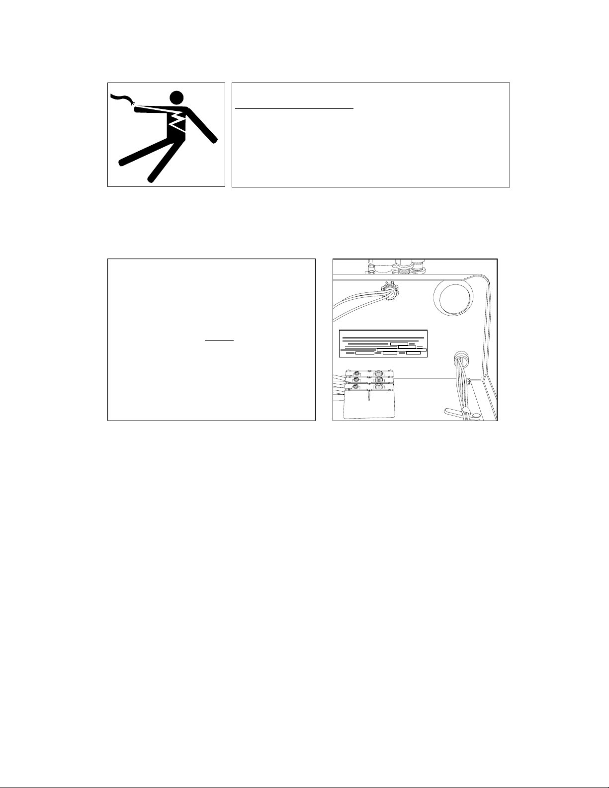
WARNING:
Electrocution or serious injury may result when working on an
energized circuit.
Disconnect power at the main breaker or service disconnect switch
before working on the circuit.
Lock-out and tag the breaker to indicate that work is being
performed on the circuit.
! ATTENTION !
A qualified electrician must connect the main incoming power to the dishwasher in accordance
with all local codes and regulations or in the absence of local codes in accordance with the
National Electrical Code.
! ATTENTION !
Electrical and grounding connections
must comply with the National Electrical Code
or in the absence of a National Code then
all Local Electrical Codes.
A qualified electrician MUST compare the
electrical power supply with the machine
electrical specifications stamped on the
MACHINE ELECTRICAL CONNECTION PLATE
located inside the control cabinet before
connecting the main power to the dishwasher.
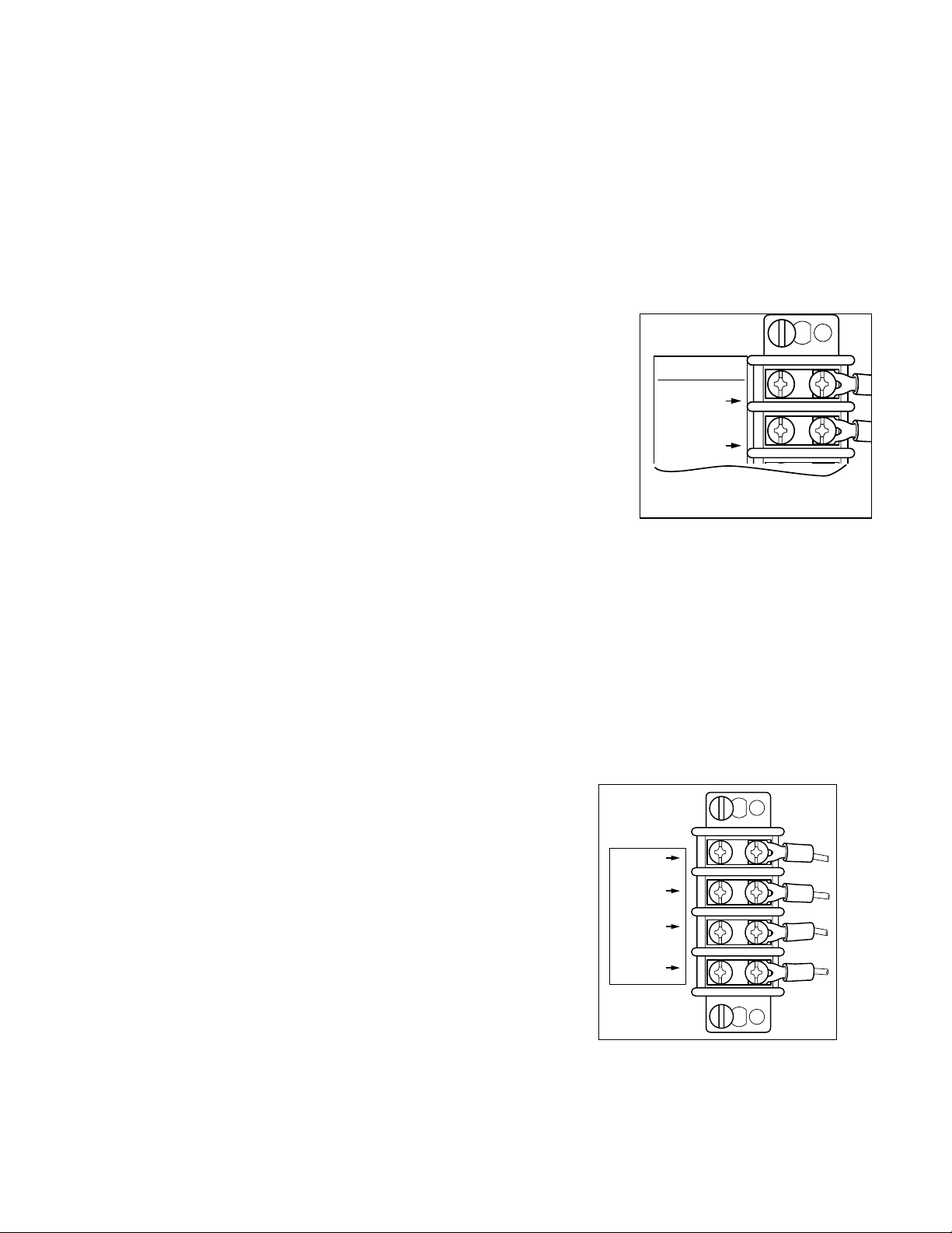
1. The incoming power to the dishwasher is made in the power terminal block,
located inside the top-mounted control cabinet.
2. The electrician must connect the incoming power based on the information
that is stamped on the Machine Electrical Connection Plate.
3. Any change to the Machine Electrical Connection Plate must be approved
by the factory in advance.
4. A knock-out plug is provided at the rear of the control cabinet for electrical
service connections.
5. Built-in electric booster heaters may have a separate main power connection.
6. Electric blower-dryers have a separate main power connection.
5
Page 14
Installation
Electrical Connections (continued)
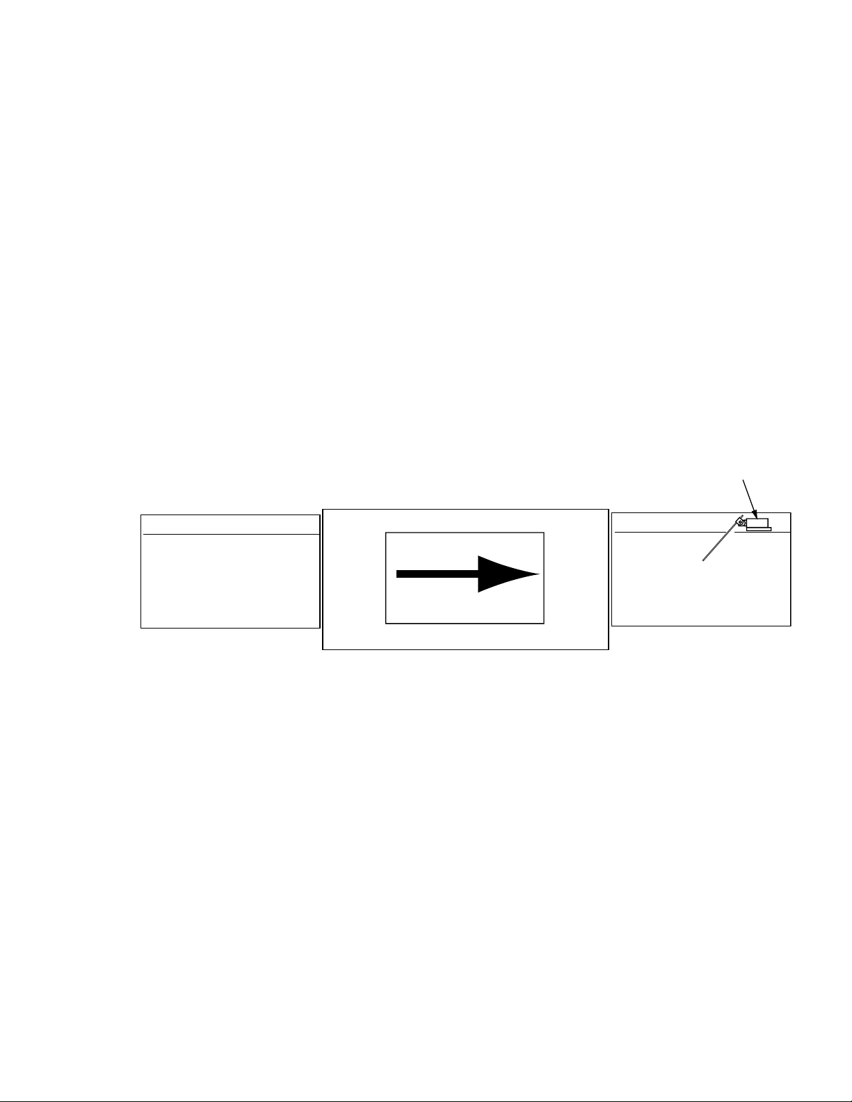
Motor Rotation
1. Check the converyor drive motor to ensure it rotates in the correct direction. The motor
shaft must rotate in a counterclockwise direction when viewed from the rear.
2. The dishwasher motors are phased together; therefore, if the conveyor motor rotation
is correct then the pumo motors will also be correct.
3. If the conveyor motor rotation is not correct, then reverse the L1 and L2 wires on the
out put side of the dishwasher main ternimal block located inside the top-mounted
control cabinet. Check to ensure the conveyor motor rotates counterclockwise after
reversing the wires.
NOTE:
The prewash, wash and rinse pump motor shafts rotate clockwise when viewed from the
rear. In addition, the motors have direction arrow labels indicating the properrotations.
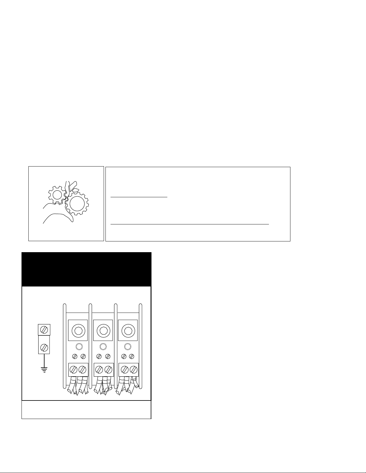
WARNING:
Moving Conveyor Parts may cause INJURY OR DEATH.
Keep hands and clothing clear of the conveyor when the
conveyor is moving.
THREE PHASE
POWER CONNECTION
LINE IN
L1 L2 L3
GRD
USE EXTREME CAUTION WHEN THE CONVEYOR IS MOVING.
Main Terminal Block Inside the Top-mounted Control
Cabinet.
6
Motor Direction Rotation Label on Motor Frame.
Page 15
Installation
(Optional) Table Limit Switch
A recommended option for any rack conveyor dishwasher is a table limit switch. The limit switch
is installed at the end of the clean-end table and is designed to stop the conveyor and pumps in
the event that dish racks back up on the clean-end table. This feature prevents possible damage
to the conveyor due to jamming. The operation of the table limit switch is described below.
1. If the dishwasher is running and the table limit switch (TLS) is activated, the GREEN cycle
light remains illuminated and the pumps and conveyor drive stop.
2. If the table limit switch (TLS) is deactivated within 5 minutes the dishwasher will resume the
cycle where it left off; after 5 minutes the green light goes out and the START button must be
pushed and a rack inserted into the machine.
3. Any dish racks left in the machine after 5 minutes have elapsed must be removed
and processed again.
4. To restart the dishwasher, make sure the table limit switch (TLS) is clear, then push the GREEN
START pushbutton and insert a rack into the load end of the machine. The green cycle light
will illuminate; the pumps and conveyor motor will run.
Soiled-end table
L-R Operation
Rack Conveyor Dishwasher
Table Limit Switch
Clean-end table
7
Page 16
Installation
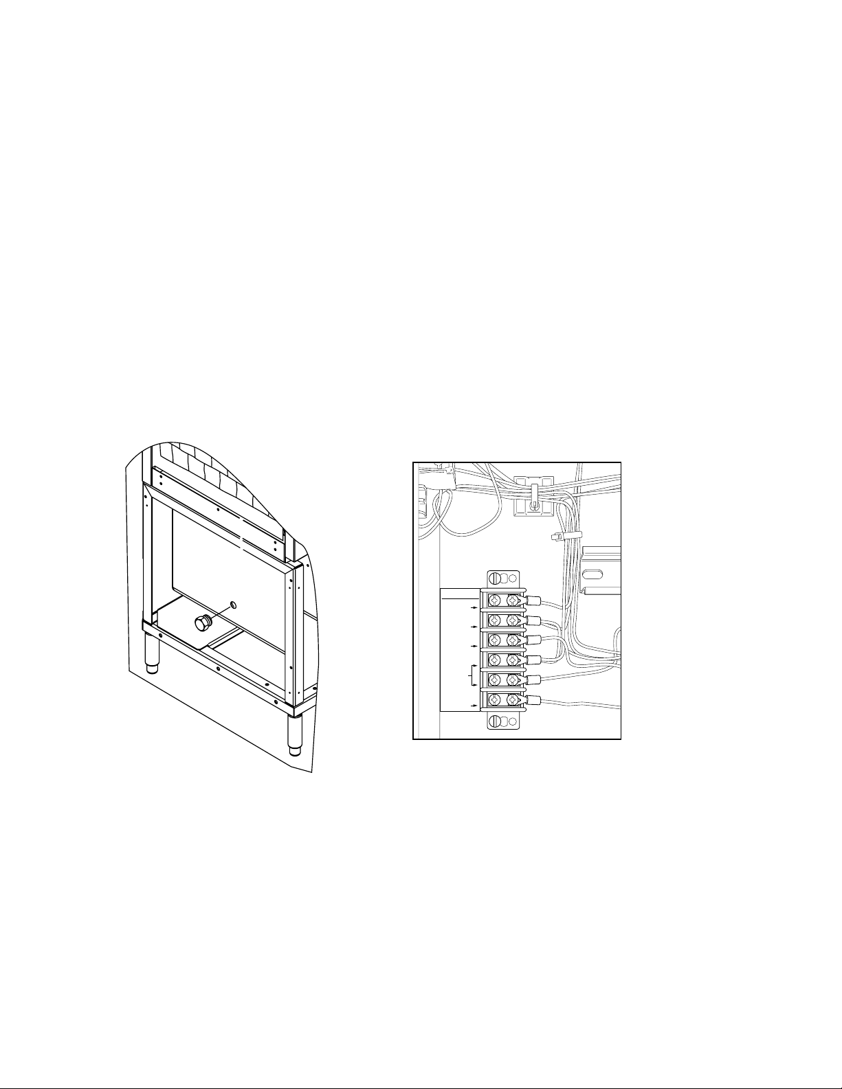
Chemical Connections
1. Use a qualified detergent/chemical supplier for detergent/chemical and
dispensing equipment needs.
2. Labeled detergent control circuit connection terminals are provided in the control
cabinet for detergent and rinse agent/sanitizer dispensing equipment (supplied by
others).
3. The illustration on the right, shows the terminal board for the machine.
4. The signal connection points include:
• Detergent signal 120VAC, 1A max load.
• Rinse aid/Sanitizer signal 120VAC, 1A load.
• Vent Fan 120VAC, 1Amp max amp load
5. A removable black plug is provided in the load end side of the wash tank for
installation of the detergent conductivity cell.
Detergent
Probe Location
SIGNAL ONLY
VENT FAN
120V
COMMON
RINSE AID
120V
COMMON
DETERGENT
120V
8
Page 17
Vent Fan Signal Connection
1. A terminal block is provided inside the top-mounted control
cabinet to provide a 120VAC, 1 AMP Max Load signal.
NOTE:
The Vent Fan Signal Connection supplies 120VAC to a control
relay (supplied by others) when the dishwasher is ON and O
VAC when the dishwasher is OFF. Power to operate the vent
fan (supplied by others) must be supplied separately.
Installation
SIGNAL ONLY
VENT FAN
120V
COMMON
RINSE AID
120V
Machine Running & Table Limit Switch Signal Connections
1. Connections are provided for systems that
require a signal to indicate the dishwasher
is running.
2. A signal connection is provided to indicate
that the dishwasher has stopped due to a
conveyor jam or when the clean dish table
is full of racks and additional racks cannot
exit the machine.
3. The table limit switch option is recommended to
be installed on all dishwashers and can be
ordered from the factory P/N 407400.
SIGNAL ONLY
MACHINE
RUNNING
TABLE
LIMIT
SWITCH
9
Page 18
Installation
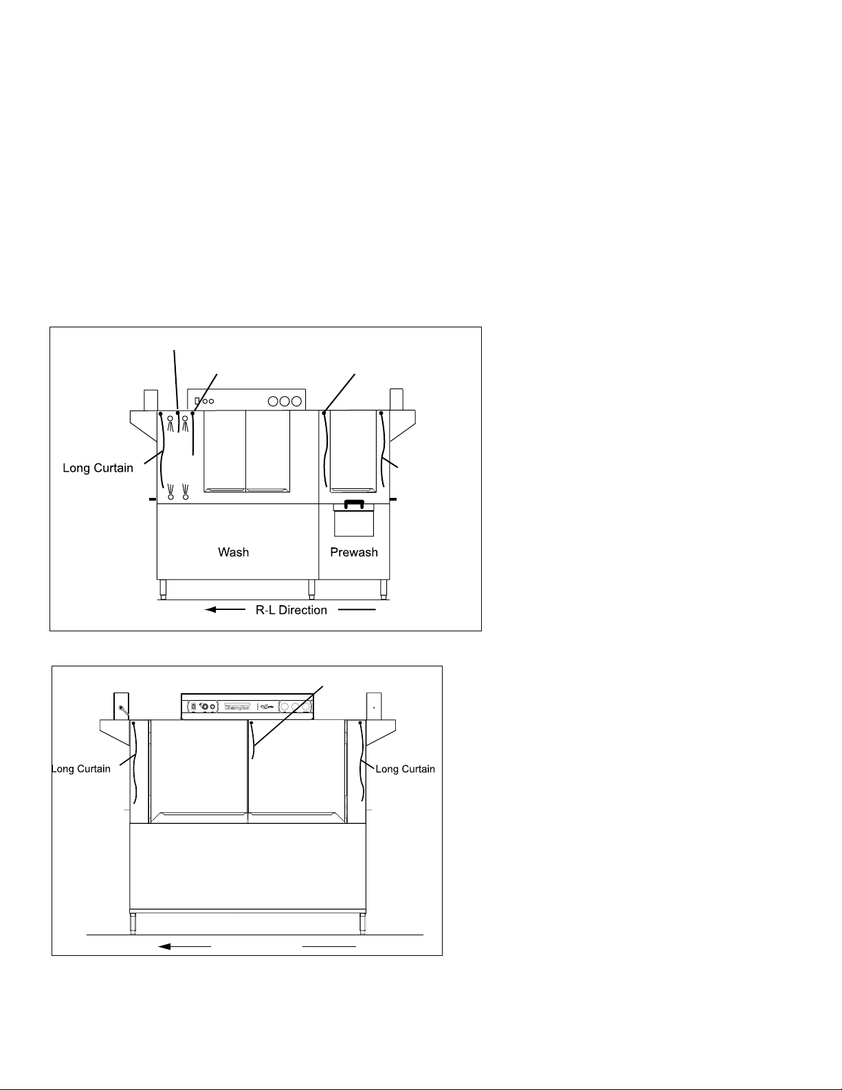
R-L Direction
Curtain Locations
1. Refer to the illustrations below and hang the curtains as shown.
J-hooks are located in the corners of each section to accept the curtain rods.
• Standard long curtains 24” x 20-1/4”
• High hood long curtains 24” x 22-3/4”
• Standard medium curtains and DR 24” x 13-1/4”
• High hood short curtains 24” x 20-1/4”
• Final rinse curtain 24” x 6-1/4”
2. Make sure the that the short flaps of the curtains face the load end of the dishwasher.
The long curtains always go on each end of the dishwasher.
Final Rinse Curtain
(DR) Dual Rinse Curtain
DRFR
Dual Rinse Single Tank Dishwasher with Prewash Curtains.
Medium Curtain
Long Curtain
Long Curtain
NOTE:
Misplacing a curtain or failing
to install a curtain will adversely
affect the proper operation of
the machine.
10
Wash Power Rinse
Two Tank Dishwasher Curtain Locations
Page 19
Installation
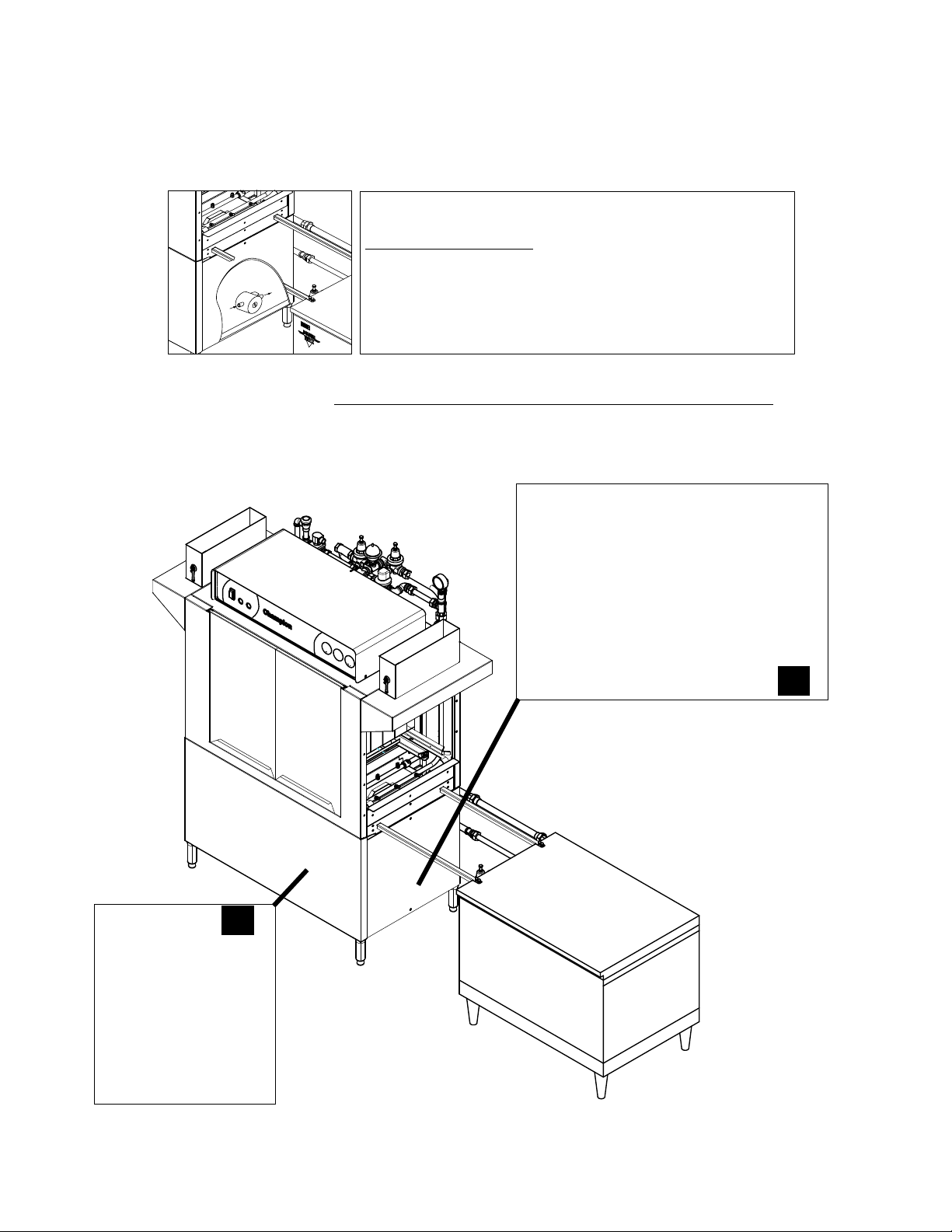
Hot Water Coil Tank Heat
Purging Air from the Dishwasher/Booster Heater System
CAUTION:
PERMANENT DAMAGE to the hot water recirculating pump can
occur if the air is not purged from the dishwasher/booster heater
system prior to placing the dishwasher into service.
Follow the instructions on pages 9-10 to prevent damage to the
dishwasher hot water recirculating pump.
The air trapped in the Dishwasher Hot Water Recirculating Pump and Water Lines must be
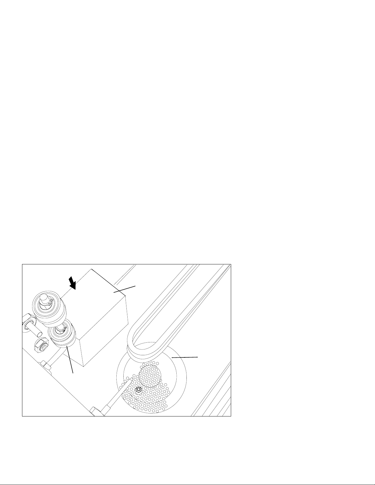
purged. Refer to the illustration below and follow the procedure on the next page.
A
The air purge petcock is located behind the dishwasher
lower front panel at the booster end of the machine.
B
The dishwasher recirculating pump is located
near the base at the booster end of the machine.
11
Page 20

Installation
Hot Water Coil Tank Heat
Purging Air from the Dishwasher/Booster Heater System (continued)
Refer to the illustration on the previous page and follow the procedure below to purge the air from the
system. Plumbing and electrical service connections must be completed before purging the system.
To purge the air:
1. Make sure the dishwasher main power switch is OFF.
2. Make sure the main water supply valve located at the booster heater is OFF.
3. Open petcock (A) on the inlet side of the dishwasher hot water heater coil.
4. Remove the silver plug located in the center of the recirculating pump.
5. Turn the main water supply valve ON. Water will begin to fill the booster heater and the dishwasher
heater coil.
6. Water and air will begin to flow out of the purge petcock and the recirculating pump and eventually
only water will be observed.
7. Turn the booster heater power switch ON.
8. Turn the dishwasher power switch ON. The dishwasher wash tank will begin to fill with water.
9. Continue to observe the petcock and the recirculating pump and make sure that there is a steady
stream of water is flowing from (A) and (B).
10. Replace the silver plug (B) in the center of the recirculating pump then close the petcock (A).
11. Turn the dishwasher power switch OFF.
12. Purging is complete.
12
Page 21
Installation
Door Safety Switches
Dishwasher access doors are equipped with a door safety switch that automatically stops
the dishwasher pumps and conveyor drive if a door is raised while the dishwasher is
running. In addition, the dishwasher will not start if a door is left open.
1. If the dishwasher is running and a door is raised, the lighted GREEN START
pushbutton goes out and the pumps and conveyor drive stop.
2. Check the interior of the dishwasher for any dish racks still in the machine.
These dish racks must be washed again to ensure they are washed and sanitized
completely.
3. To restart the dishwasher, make sure all doors are closed, then push the GREEN
START pushbutton.
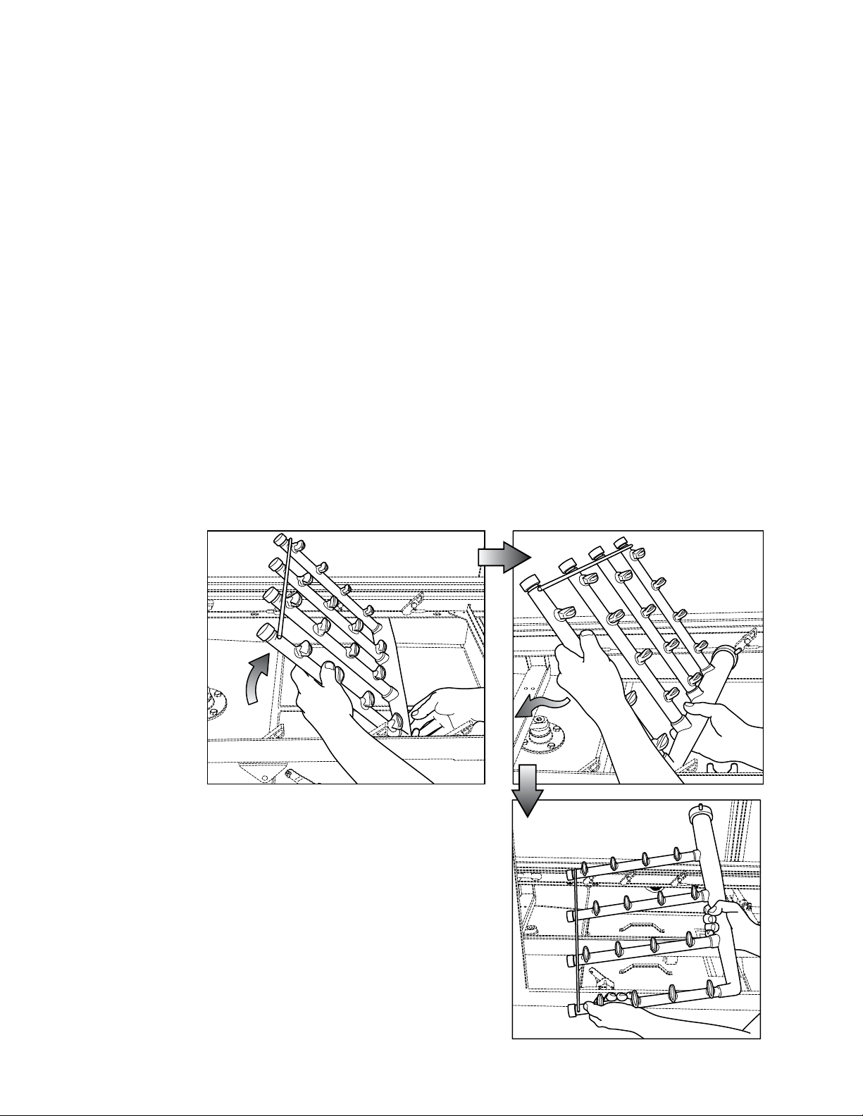
Spray Arm and Scrap Screen Installation
The illustrations below and on the following pages illustrate how to install and
remove the spray arm assemblies and scrap screens.
Removing the lower spray arm assembly
13
Page 22
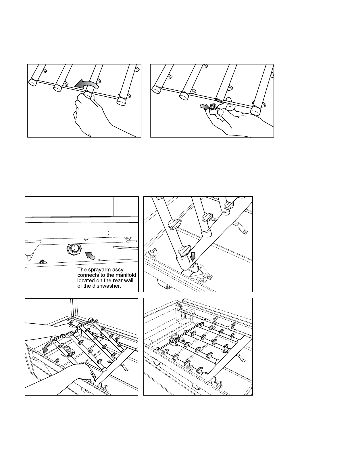
Installation
Removing the Spray Arm End Plugs
Installing the Lower Spray Arm Assembly
14
Page 23
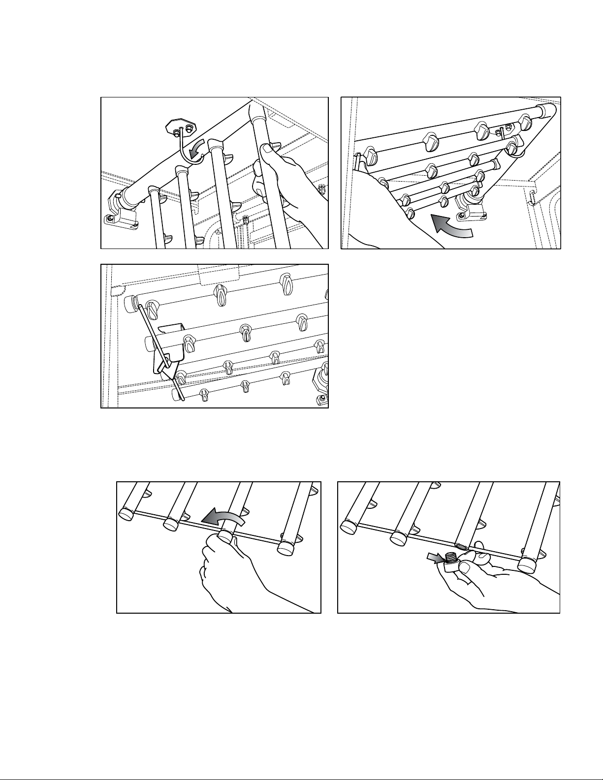
Installation
Installing the Upper Spray Arm Assembly
Removing the Spray Arm End Plugs
15
Page 24
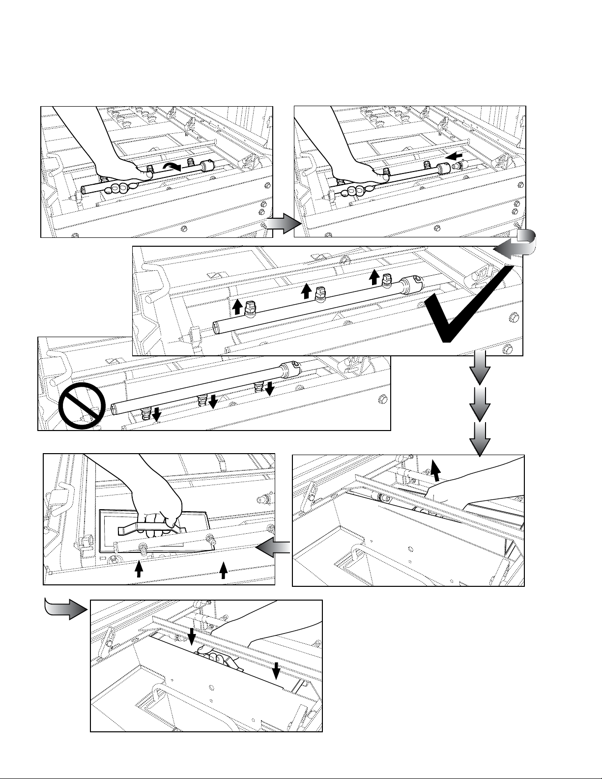
Installation
Removing the Dual Rinse (DR) scrap screens
Refer to the illustrations on this and the next page to remove and install the Dual
Rinse (DR) scrap screens and rinse arm.
16
Page 25
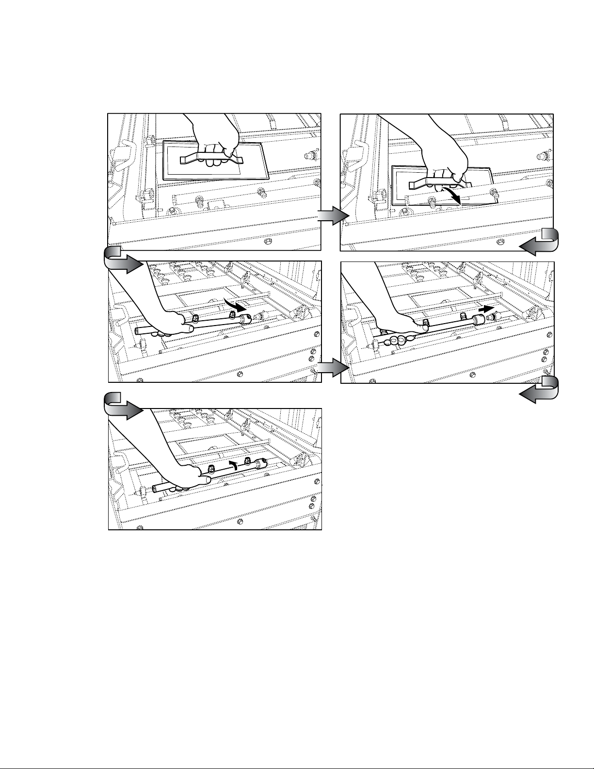
Installation
Installing the Dual Rinse (DR) scrap screens
17
Page 26

Installation
Check list
1. Remove white protective film from the dishwasher exterior.
2. Install lower panels to the dishwasher.
3. Remove any foreign material from inside of the machine.
4. Check that the chemical supplies (supplied by others) are full.
5. Check to ensure the dishwasher drains are closed.
6. Install scrap screens, baskets and spray arms.
7. Turn main utilities to the dishwasher ON. (Power, water, steam if applicable).
8. Make sure doors are closed.
9. Turn dishwasher power switch ON. The tanks fill with water and the tank and booster
heat will come on.
NOTE:
The dishwasher will not start if the tanks are not full of water. If the dishwasher fills for
more than 20 minutes, the dishwasher will shut down and the green indicator light will
flash. Check the drain valves and make sure they are fully closed, then push the power
switch OFF and back ON and push the Green Start button to resume operation.
10. Check the digital tank water temperature gauges to ensure they indicate the proper
levels. The final rinse gauge displays OFF when the final rinse is not running.
11. Check for leaks.
12. Push the START button.
13. Insert an empty dish rack into the load end of the dishwasher.
The pumps and conveyor will run.
14. Carefully, open each dishwasher door to make sure the safety switch stops the
conveyor and pumps.
15. Restart the dishwasher by pressing the START button.
16. Allow the dish rack to travel to the unload end of the dishwasher. The final rinse
will run.
17. Allow the rack to exit the dishwasher. The dishwasher pumps and conveyor should
stop when the rack exits the dishwasher.
18. Push the Stop button when the machine is running and the dishwasher should stop.
19. Push the START button, insert a dish rack into the load end of the machine and the
pumps and conveyor should start.
20. Push the dishwasher Power Switch OFF. The dishwasher should shut down.
21. Drain the dishwasher and check that floor drains can handle the water volume leaving
the dishwasher.
NOTE:
Opening a door will stop the pumps and drive. If the door is closed within 5 minutes the
machine will resume operation where it left off. After 5 minutes the START switch must
be pressed and a dish rack inserted into the machine for normal operation.
18
Page 27

Operation
Operation
1. Check that the spray pipes, curtains, and scrap screens are in place and clean.
2. Check that the overflow drains are closed.
3. Check the chemical supplies (supplied by others). Turn on the detergent dispenser switches.
4. Turn on the exhaust vent system (if applicable), and make sure it is operating.
5. Close the door(s). Push the power switch ON..
Machine will begin to fill through the fill valve and the final rinse piping.
6. When the tanks are full, wait until the wash tank digital temerature guage has reached the
proper temperature. The digital tank temperature gauges are located on the control cabinet.
Minimum wash temperatures are:
• All single tank models - 160°F/71°C to 175°F/79°C
• Single tank with Prewash - Wash Tank 160-175°F/71-79°C
• The Prewash tank for all models has no temperature rating.
• 2-tank (Wash Tank) 150-165°F TO 66°F/74°C
(Power Rinse Tank) 165-180°F TO 74°F/82°C
• Final Rinse for all models is a minimum of 180-195°F/82-91°C.
• Dual Rinse (if equipped) is 165-180°F/74-82°C rinse for all models.
7. Push the Green START button. The Green Cycle Light illuminates indicating the dishwasher
is ready for automatic operation.
8. Pre-scrape wares to remove large food particles and load wares into the dish racks.
9. Pegged racks are for plates and/or trays. Flat racks are for bowls and/or silverware.
Spread silverware evenly in a single layer in a flat rack or upright (loosely packed) in a
cutlery rack/cylinder.
10. Push a dish rack into the load-end of the dishwasher until it contacts the idle pump
switch lever, the conveyor and pumps will start.
11. The dishwasher will run for 90 seconds to wash, rinse and move the dish rack out
of the unload end of the dishwasher.
12. Inserting another dish rack into the machine before the first rack exits will keep the
dishwasher running until the last dish rack exits the machine.
13. Check the final rinse pressure and temperature as the racks pass through the final
rinse. This final rinse pressure MUST be 20-22 psi and the final rinse temperature
MUST be a minimum of 180-195°F/82-91°C .
14. The pumps and the conveyor drive will automatically stop after the last rack exits
the machine.
15. The machine may be stopped at any time during the cycle by pressing the red STOP
pushbutton. The green light will go out.
16. Check the interior of the dishwasher for any dish racks still in the machine.
These dish racks must be washed again to ensure they are washed and sanitized
completely.
17. To restart, push the green START pushbutton and push another dish rack into the
dishwasher load end until the pumps and conveyor start.
18. Repeat steps 7-10 until all wares are washed.
19
Page 28
Operation
Pump Intake
Screen
Dual Float
Switch
Drain
Screen
Door Safety Switches
Dishwasher access doors are equipped with a door safety switch that automatically stops
the dishwasher pumps and conveyor drive if a door is opened while the dishwasher is
running. In addition, the dishwasher will not start if a door is left open.
1. If the dishwasher is running and a door is opened, the GREEN cycle light
remains illuminated and the pumps and conveyor drive stop.
2. If the door is closed within 5 minutes the dishwasher will resume the cycle where it
left off; after 5 minutes the green cycle light goes out and the START button must be
pushed and a rack inserted into the machine.
3. Any dish racks left in the machine after 5 minutes have elapsed must be removed
and processed again.
4. To restart the dishwasher, make sure all doors are closed, then push the GREEN
START pushbutton and insert a rack into the load end of the machine. The green
cycle light will illuminate; the pumps and conveyor motor will run.
Pump Intake Screen and Dual Float Switch
Refer to the illustration below and note the location of the pump intake screen and dual float
switch.
1. Make sure the pump intake screen is installed by sliding it on the bracket located in front
of the wash pump intake.
2. Make sure the float balls on the dual float switch move freely on the float stem.
3. Check the interior of the tank for any foreign objects and make sure the drain screen is
clean.
Make sure tank is clean, the pump intake screen is installed and the dual float switch
moves freely.
20
Page 29

Blank Page
This Page
Intentionally
Left Blank
21
Page 30
Operation
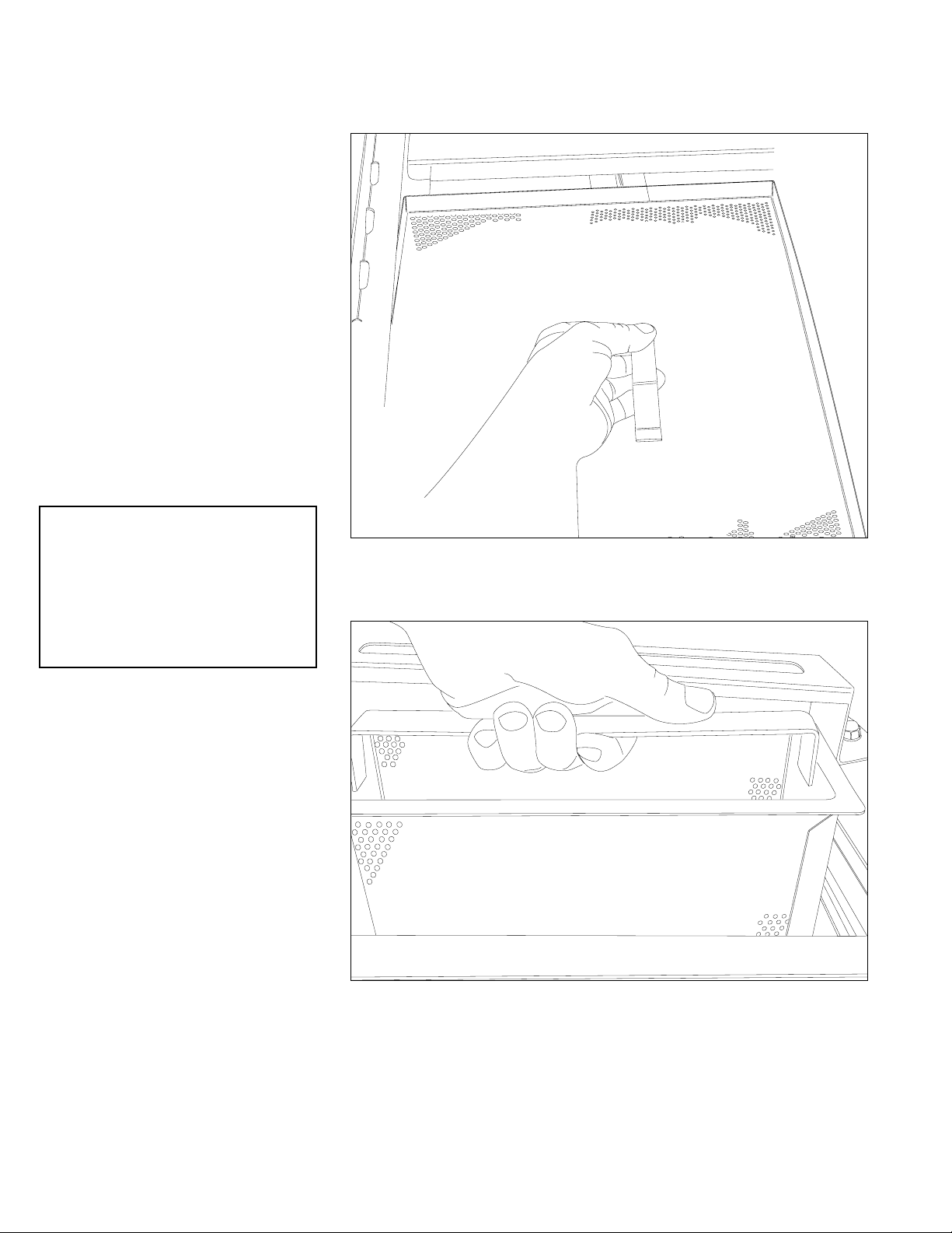
Scrap Screens
1. All models have scrap
screens in the tanks.
2. Install two scrap screens in
each wash tank making sure
they fit securely without large
gaps between them.
3. Install an internal refuse
basket in each wash tank.
4. If equipped, install one large
scrap screen and one
external refuse basket in the
prewash tank.
5. For machines equipped with
a dual rinse section, install
two scrap screens in the dual
rinse section.
! ATTENTION !
NEVER REMOVE A SCRAP
SCREEN OR REFUSE BASKET
WHEN THE DISHWASHER IS
RUNNING.
There are have scrap screens in the wash tank and one in the prewash tank
22
There is one refuse basket in the wash tank and an external basket in the prewash
Page 31

Cleaning
Cleaning your dishwasher is the best maintenance you can perform.
The cleaning intervals below are the minimum requirements for most dishwashers.
You may need to clean your dishwasher more often when washing heavily soiled wares
or during long hours of continuous operation.
Cleaning
Daily or every 2 hours of operation
1. Turn power switch to OFF.
2. Open drain lever(s) to drain water. Remove scrap screens and scrap baskets.
Clean inside of the tanks and flush with clean water.
Back flush the scrap screens until clean then reinstall in the machine.
DO NOT STRIKE SCREENS OR BASKETS AGAINST SOLID OBJECTS
3. Remove the spray arm assemblies. Remove the end cap from each spray arm.
4. Flush the spray arms and nozzles to remove any debris.
5. Replace the end caps. Check the condition of the manifold O-ring.
6. Reinstall the spray arms.
7. Remove and clean the curtains. Allow them to dry at the end of the day.
8. Leave the doors open between operations, allowing the machine to dry.
9. Make sure the final rinse nozzles are clear of mineral deposits.
10. Straighten a metal paper clip and use to clean the nozzles.
11. Check the temperature and pressure gauge readings during operation.
12. Inspect the machine for signs of water leaks.
13. Check the chemical supplies and refill as necessary.
23
Page 32

Cleaning
Cleaning (continued)
At the End of the Day
1. Perform Steps 1-10 on the previous page.
2. Remove the upper and lower rinse and wash spray arms and end plugs and flush with fresh
water.
3. Remove the Dual Rinse (DR) rinse arm assemblies and flush with fresh water.
4. Clean the final rinse arm nozzles using a small paper clip.
5. Remove the curtains and clean with fresh water.
DO NOT USE STEEL WOOL TO CLEAN THE INTERIOR OF THE MACHINE.
6. Wipe the interior and exterior of the machine with a soft cloth and a mild detergent.
DO NOT HOSE THE EXTERIOR OF THE MACHINE WITH WATER.
7. Reassemble the dishwasher and leave the door open to allow overnight drying
8. Contact the chemical supplier for de-liming if required.
De-liming
Lime (scale) deposits are the result of minerals contained in the water feeding the dishwasher
and appear as a white haze on the surface of the dishwasher. Severe scaling can appear as a
granular deposit. These deposits are a result of the mineral content in the geographic area of the
machine's location.
WARNING:
Death or injury can result from toxic fumes when de-liming agents come in
contact with Chlorine Bleach, or other chemicals that contain iodine, bromine,
or fluorine.
USE EXTREME CAUTION WHEN HANDLING ANY DE-LIMING AGENT
CAUTION:
De-liming agents can cause chemical burns. Wear rubber gloves, eye protection and any other protective clothing as instructed by a qualified chemical
supplier and follow the instructions provided by the chemical supplier.
! ATTENTION !
Place a flat-bottom dish rack upside down on the idle pump start switch at the
entrance end f the dishwasher to keep the dishwasher running during the
de-liming procedure.
24
Page 33

Weekly
1. Inspect all water lines for leaks and tighten at joints if required.
2. Clean any detergent residue from the exterior of the machine.
3. Check the drain operation.
4. Clean any accumulated scale from the heating element.
5. Inspect the spray arms for any damage or missing parts.
6. Inspect the final rinse arms for missing parts.
7. Inspect the drive assembly and cradle for damaged or missing parts.
8. Check that float switches move freely.
9. Check the idle pump actuator and the final rinse actuator for freedom of travel.
Monthly
Maintenance
Maintenance
1. Inspect interior of machine for lime deposits and clean.
2. Check o-rings on spray arm piping connections.
3. Check the drain operation.
4. Clean any accumulated scale from the heating element.
5. Inspect the spray arms O-rings and ensure all plugs are installed.
6. Inspect the final rinse arms for missing parts and are clean.
7. Inspect the drive assembly and cradle for damaged or missing parts.
8. Check that float switches move freely.
9. Check the idle pump actuator and the final rinse actuator for freedom of travel.
10. Check the drive belt and adjust as necessary.
11. Check the pump rotation and direction of rotation.
12. Check the operation of temperature gauges or displays.
13. Perform complete operation check.
Yearly
1. Contact authorized service agent to perform complete maintenance review of machine.
2. Correct any abnormal situations as recommended.
25
Page 34

Digital Display
i
-
E-Rack Digital Temperature Display Meters
! ATTENTION !
The Digital Temperature Displays only indicate temperature, they do not control
booster heaters. Electromechanical thermostats continue to control the tank and final rinse heat
circuits.
1. The analog temperature gauges have been replaced with digital temperature display meters.
2. The meters display temperatures for the prewash tank (if equipped), the wash tank,
power rinse tank (if equipped), the dual rinse (DR) tank (if equipped), and the final rinse.
3. A meter displays temperature in 2 ways:
a. The first display is a semi-circular LED bar that moves from left to right as the temperature
increases in magnitude. The color of the bar changes from black, to orange, and to green.
b. The second display is a 3 digit LED that changes from OFF if the tank or final rinse heat is
disabled, to Blank and from a minimum temperature of 70
o
F to the maximum calibrated
temperature set point of the meter.
(Refer to the "Display Meter Operation Checks" on
the next page to change a Meter set-point.)
wash tank or final rinse
Control cabinet showing digital temperature display meters on the right-hand side of the control cabinet.
LED Bar
3 digit
LED
Close-up view of the display meters. Note the sem
and the numeric readouts in the center.
circular indicator bars
26
Page 35

Digital Display
Display Meter Operation Checks
Check the Meter LEDs:
1. Turn the Dishwasher Power Switch ON. The 3-digit LEDs illuminate simultaneosly, the each LED
bar illuminates from left-to-right.
Check the Meter Temperature Set-point:
Refer to the photo below and the "Rear view of the Digital Displat Circuit Board" on the next page.
1. Remove the top-mounted control cabinet panel. Locate the CHECK pushbutton on the rear of
the display. The pushbutton is located at the top and center of the board.
2. There are 6 set-point values: 70, 120, 150, 160, 165, and 180°F.
3. Turn the dishwasher Power Switch ON, then Push and Hold the CHECK pushbutton. Meter 1
flashes the current user-defined set-point. Meter 2 is blank.
4. Continue to Hold the CHECK pushbutton. Meter 1 blanks out and Meter 2 flashes its current
set-point value of 70, 120, 150, 160, 165, and 180°F.
5. Release the CHECK button. Meter 1 and Meter 2 display the actual temperatures in the wash
tanks.
6. A final rinse Meter will dislay OFF until the final rinse switch is activated, then the meter
displays the actual final rinse temperature which is measured at the final rinse manifold.
Check the Meter Temperature Set-point:
The set-point determines how the meter displays the yellow and green bar. For example, if the setpoint is 70, then the bar displays yellow from 0-70, then green from 70 and above.
1. Push and Hold the CHECK oushbutton until Meter 1 display flashes.
2. Release the CHECK pushbutton. Meter 1 goes through the set-point values each time the
CHECK pushbutton is pushed and released. The set-point value advances from 70, 120, 150,
160, 165, and 180°F.
3. When the new set-point appeats on the display, hold the CHECK pushbutton until the display
flashes. The number that is displayed is the new-set-point. If the display advances past the
desired set-point, repeat Steps 1-2.
4. In order to change Meter 2, Push and Hold the CHECK pushbutton until Meter 1 flashes.
Continue to Hold the CHECK pushbutton until Meter 2 flashes, and then repeat Steps 2-3 for
Meter 2.
7 0
Set-point value of 70°F
E
Important:
The letter "E" appears in the center
of the 3-digit display when the
thermistor is shorted or open.
27
Page 36

Digital Display
t
Calibration
Calibration is an internal function of the display circuit board and does not calibrate temperayure
control of th dishwaher components.
NOTE:
The Thermistor Plug and 1 wire from the Rinse Switch Connector must be disconnected from the
display circuit board before calibration.
To calibrate the display board:
1. Turn dishwasher Power Switch OFF.
2. Disconnect the thermistor plug and at least 1 wire from the rinse switch connector.
3. Turn Power Switch ON.
4. Press and Hold the CHECK pushbutton while pressing and releasing the RESEt button.
5. Release the CHECK oushbutton.
6. Display shows "CAL" flashing on METER 1 and METER 2.
NOTE:
If the display shows "EEE", then the thermistor plug is not disconnected. Disconnect the thermistor
plug and repeat Steps 1-6 above.
7. Press and Hold the TEST A pushbutton to calibrate Meter 1 (Test B for Meter 2).
8. The display calibrates and shoes "160".
9. Release TEST A pushbutton. An "E" flashes in the center of METER 1.
10. Press the RESET pushbutton to exit the calibration mode.
11. Repeat Steps 2-8 tp calibrate Meter 2.
12. Turn the dishwasher Power Switch OFF and reconnect the thermistor plug and rinse switch
connector wire.
13. Turn Power Switch ON and return to normal operation.
1 2
Thermistor was ot unplugged
before calibration
Display board is in the
calibration mode
Disconnect
thermistor
plug
Temperature
display
Selector switch
o
F or oC
Disconnec
a rinse
switch wire
3
Meter calibrated
28
0
4
Calibration complete when
"E" flashes
Rear Detail View of DIgital Display Circuit Board
Page 37

Digital Display
Display Codes and Definitions
The illustrations below show the codes that may appear in the temperature meter displays.
29
Page 38

Condition Cause Solution
Dishwasher will not run.
Low or no water.
Door not closed.
Main power OFF.
Dishwasher OFF.
Wash tanks not full
Main water supply off.
PRV setting incorrect or low
incoming pressure.
Solenoid strainer clogged.
Solenoid valve defective.
Defective float switch.
Close door completely.
Check breaker on panel.
Turn dishwasher ON.
Check drain valves.
Open supply valve.
Adjust the PRV to 22psi
flowing pressure.
Clean strainer.
Contact Service Agent.
Contact Service Agent.
Dishwasher stays in
wash cycle.
Conveyor jammed or table
limit switch has stopped
conveyor.
Green start button not
pressed.
Machine filled for 20
minutes but did not reach
fill level and shut down.
Contact Service Agent.
Contact Service Agent.
Poor wash results.
Detergent not added to tank.
Wares incorrectly loaded.
in dishrack.
Clogged screens .
Clogged spray arms.
Thermostat defective.
End plugs missing.
Water temperature low.
Check detergent suppy.
Reposition wares or reduce
amount of wares.
Clean screens.
Clean spray arms.
Contact Service Agent.
Check spray arms.
Check incoming water
temperature.
Dishwasher conveyor
will not run.
Idle pump switch defective.
90 second timer defective
Check conveyor for jams
Remove racks from load
end of table.
Press Green start button &
insert rack into machine.
Check drain valves, turn
power ON and OFF, then
push Green Start button.
Incoming water temperature
low.
Defective heater.
Defective temperature
display.
Low tank and/or final
rinse temperature.
Check incoming temperature/contact maintenance.
Contact service agent.
Contact service agent.
Troubleshooting
Troubleshooting
Before calling for service, check the following conditions.
1. Dishwasher main power and water supply is on.
2. Machine has been assembled correctly.
3. Conveyor is clear of any obstructions.
4. Drains are closed.
5. Screens and pump intake screens are clear.
6. Doors are closed and secure.
30
Page 39

Service Replacement Parts
Illustration ......................................................................................................Page
Front View of Control Panel
Control Cabinet Interior View for Single Tank Models with Dual Rinse ........................ 35
Control Cabinet Interior View for Two Tank Models ................................................. 37
Prewash Panels and Curtains ................................................................................ 44
Single Tank Panels and Curtains ........................................................................... 46
Two Tank Panels and Curtains ............................................................................... 48
Drive Motor Assembly.......................................................................................... 50
Conveyor Drive Assembly .................................................................................... 52
Prewash Track and Cradle Assembly ..................................................................... 54
Single Tank Track and Cradle Assembly ................................................................. 56
Two Tank Track and Cradle Assembly .................................................................... 58
Prewash Scrap Screens ........................................................................................ 60
Single Tank Scrap Screens.................................................................................... 62
Two Tank Scrap Screens ....................................................................................... 64
Prewash Wash Spray Arms .................................................................................. 66
Single Tank Wash Spray Arms .............................................................................. 68
Two Tank Wash and Power Rinse Spray Arms......................................................... 70
.................................................................................. 33
Dual Rinse (DR) Tank Assembly ............................................................................. 72
Dual Rinse (DR) Pump/Motor Assembly .................................................................. 74
Prewash Pump Suction and Discharge ................................................................... 76
Wash and Power Rinse Pump Suction and Discharge .............................................. 78
Pump/Motor Assembly ........................................................................................ 80
Float Switches ..................................................................................................... 82
Single Tank Electric Wash Tank Heat ..................................................................... 84
Two Tank Electric Wash and Rinse Tank Heat .......................................................... 86
Thermostats and Thermistors ................................................................................. 88
Junction Box ....................................................................................................... 90
Final Rinse Piping (All Models) .............................................................................. 92
Fill Piping (All Models) ......................................................................................... 94
Prewash Cold Water Tempering (CWT) Piping ........................................................ 96
(Continued on next page)
31
Page 40

Service Replacement Parts (continued)
Illustration ......................................................................................................Page
Single and Two Tank Electric Booster Assembly 40°F/70°F
Single Tank Booster Heaters 40°F/70°F ................................................................. 100
Two Tank Booster Booster Heaters 40°F/70°F ......................................................... 102
Two Tank and Heat Recovery Electric Booster Cabinet ............................................. 104
Two Tank Steam Heat with K2 Steam Booster.......................................................... 106
Single Tank Steam Heat ....................................................................................... 108
Two Tank Steam Heat .......................................................................................... 110
22", 26" and 36" Prewash Drain Assemblies ......................................................... 112
E44DR with and without Prewash Drain Assembly ................................................... 114
E54DR with and without Prewash Drain Assembly ................................................... 116
E64 with and without Prewash Drain Assembly ....................................................... 118
E84 Drain Assembly ............................................................................................ 120
E84 with Prewash Drain Assembly ........................................................................ 122
Final Rinse Drain Assembly................................................................................... 124
22" Prewash Door Assembly ................................................................................ 126
E44 and E54 Door Assembly ............................................................................... 128
E64, E84 and 36" Door Assemblies ...................................................................... 130
...................................... 98
Extended Vent Cowls and Splash Shields ............................................................... 132
Standard Vent Cowls ........................................................................................... 134
Single Tank Hot Water Coil (HWC) Heat ............................................................... 136
Two Tank Hot Water Coil (HWC) Heat................................................................... 138
24" Sideloader ................................................................................................... 140
30" Sideloader ................................................................................................... 142
Dish Racks ......................................................................................................... 144
32
Page 41

Front View of Control Cabinet (All Models)
2
1
2
1
3
Models: E66DRPW, E76DRPW, E70DRFFPW, E80DRFFPW, E80DRHDPW, E90DRHDPW
3
4
4
2
1
3
4
Models: E44DR, E54DR
5
6
Models: E64, E84
7
L-R and R-L Machine Direction Shown
L-R and R-L Machine Direction Shown
L-R Machine Direction Shown
10
WASH FINAL RINSE
9
11
PREWASH WASH FINAL RINSE
10
9
10
11
WASH RINSE FINAL RINSE
10
10
9
9
9
11
11
11
11
2
Models: E86PW, E106PW, E90FFPW, E110FFPW, E100HDPW, E120HDPW
9 9
10
10
11
1
3
4
L-R Machine Direction Shown
8
PREWASH WASH RINSE FINAL RINSE
Item Part Description Qty.
No. No.
1 114505 Breaker, Switch14A ON/OFF 24VAC, 1
2 0512232 Light, Indicator Green LED 2VDC 1
3 115019 Pushbutton, Switch Green 1
4 115018 Pushbutton, Switch Red 1
5 114532 Decal (L-R, and R-L) (See illustration above for model nos.) 1
6 114533 Decal, (L-R and R-L) (See illustration above for model nos.) 1
7 114436 Decal, (L-R) (See illustration above for model nos.) 1
--- 114534 Decal, (R-L) (See illustration above for model nos.) 1
8 114437 Decal, (L-R) (See illustration above for model nos.) 1
--- 114438 Decal, (R-L) (See illustration above for model nos.) 1
9 114489 Gauge, Digital Temperature Display (Order with Item 10) A/R
--- 114559 Support, Circuit Board (4 per board) A/R
10 114934 Suppressor, Transient Voltage (Order with Item 9) 1
11 114508 Cable Assy., 4-conductor Thermistor (1per display board) 1
33
Page 42

Control Cabinet Interior View for Single Tank Models with Dual Rinse- Layout 1
Note: Control Cabinet Cover P/N 334879 not shown.
7
20
212121232323
6
22
BC WC
HEAT
7CR1CR
5 5 5
BC
HEAT HEAT
24
8
6M DC
9
11
11
10
12
3M 2M
13
1M
14
15
4
16
17
16
16
16
18
27
19
2
8
28
26
18
3
1
This illustration shows a control cabinet with all options. Your control cabinet may not
have the prewash components nor the additional parts required for the 22KW booster.
Please disregard these extra components as necessary.
29
18
25
1MOL2MOL3MOL
34
Page 43

Control Cabinet Interior View for Single Tank Models with Dual Rinse
Item Part Description Qty.
No. No.
COMMON ELECTRICAL PARTS (Not Voltage Specific)
1 114756 Circuit Board, Control 1
--- 114759 Support, Circuit Board 4
2 115147 Block, Terminal 10-Pole 1
--- 115345 Jumper, Slotted 1
3 115158 Label (TLS, Machine Run, etc.) 1
4 114898 Transformer, 120:24VAC 20VA 1
5 111827 Contactor, Heat 60 FLA A/R
6 103310 Lug, Ground Wire 1
7 111833 Block, Input Terminal 175A, 3-Pole 1
8 111153 Block, Fuse 600V 30A 2
9 114519 End Block, E/NS 35 N 1
10 114512 Terminal, Single ST 2.5 Gray 4
11 111068 Relay, 2PDT, 10A 120VAC 2
12 111036 Socket, Relay 2
13 114521 End Cover, Single Terminal D-MZB 1.5 NS35 1
14 114520 Terminal, Single MZB 1.5 NS35 6
15 114522 Bridge, Terminal 10-Pole FBS 10-5 (Cut to fit) 1
16 108122 Contactor, 12A A/R
17 115161 Relay, DPDT 30A 120VAC (DR Pump) 1
18 112367 Contact, Auxiliary GVAN11 A/R
19 111633 Bus-System, 2-units (Drive and Wash) 1
--- 111671 Bus-System, 3-units (Drive, Prewash, Wash) 1
VOLTAGE SPECIFIC PARTS:
200-220V/60/3 (Wash Tank Heat)
20 180171 Block, Fuse 600V 60A 3P J Type 1
21 180175 Fuse, J 50A 600V 3
200-220V/60/3 (12KW Booster)
22 180171 Block, Fuse 600V 60A 3P J Type 1
23 180174 Fuse, J 45A 600V 3
200-220V/60/3 (22KW Booster)
22 108424 Block, Fuse 600V 100A 3P T Type 1
23 180059 Fuse, T 80A 250V 3
(Continued on next page)
35
Page 44

Control Cabinet Interior View for Single Tank Models with Dual Rinse
Item Part Description Qty.
No. No.
VOLTAGE SPECIFIC PARTS:
200-220V/60/3
24 111822 Fuse, Line 120VAC, 5A 600V LPCC-5 2
25 111624 Overload, Motor (Drive) 0.63-1.0A 1
26 111628 Overload, Motor (Prewash) 4.0-6.3A 1
27 111629 Overload, Motor (Wash) 6.0-10.0A 1
28 100922 Fuse, DR Heat 600V 20A, ATMR-20 2
29 107091 Transformer, 500VA 1
230-240V/60/3 (Wash Tank Heat)
20 180171 Block, Fuse 600V 60A 3P J Type 1
21 180174 Fuse, J 45A 600V 3
230-240V/60/3 (12KW Booster)
22 180171 Block, Fuse 600V 60A 3P J Type 1
23 180173 Fuse, J 40A 600V 3
230-240V/60/3 (22KW Booster)
22 108424 Block, Fuse 600V 100A 3P T Type 1
23 180060 Fuse, T 70A 250V 3
230-240V/60/3
24 111822 Fuse, Line 120VAC, 5A 600V LPCC-5 2
25 111624 Overload, Motor (Drive) 0.63-1.0A 1
26 111628 Overload, Motor (Prewash) 4.0-6.3A 1
27 111629 Overload, Motor (Wash) 6.0-10.0A 1
28 100922 Fuse, DR Heat 600V 20A, ATMR-20 2
29 107091 Transformer, 500VA 1
460-480V/60/3 (Wash Tank Heat)
20 111135 Block, Fuse 600V 30A 3P J Type 1
21 180243 Fuse, J 25A 600V 3
460-480V/60/3 (12KW Booster)
22 111135 Block, Fuse 600V 30A 3P J Type 1
23 112062 Fuse, J 20A 600V 3
460-480V/60/3 (22KW Booster)
22 180171 Block, Fuse 600V 60A 3P J Type 1
23 180172 Fuse, J 35A 250V 3
(Continued on next page)
36
Page 45

Control Cabinet Interior View for Single Tank Models with Dual Rinse
Item Part Description Qty.
No. No.
VOLTAGE SPECIFIC PARTS:
460-480V/60/3
24 111821 Fuse, Line 120VAC, 5A 600V LPCC-3 2
25 111624 Overload, Motor (Drive) 0.63-1.0A 1
26 111626 Overload, Motor (Prewash) 1.6-2.4A 1
27 111627 Overload, Motor (Wash) 2.5-4.0A 1
28 100913 Fuse, DR Heat 600V 10A, ATMR-10 2
29 107091 Transformer, 500VA 1
575V/60/3 (Wash Tank Heat)
20 111135 Block, Fuse 600V 30A 3P J Type 1
21 112062 Fuse, J 20A 600V 3
575V/60/3 (12KW Booster)
22 111135 Block, Fuse 600V 30A 3P J Type 1
23 111682 Fuse, J 15A 600V 3
575V/60/3 (22KW Booster)
22 111135 Block, Fuse 600V 30A 3P J Type 1
23 111683 Fuse, J 30A 600V 3
575V/60/3
24 107289 Fuse, Line 120VAC, 2.5A 600V LPCC-2-1/2 2
25 111624 Overload, Motor (Drive) 0.63-1.0A 1
26 111626 Overload, Motor (Prewash) 1.6-2.4A 1
27 111627 Overload, Motor (Wash) 2.5-4.0A 1
28 100913 Fuse, DR Heat 600V 10A, ATMR-10 2
29 111046 Transformer, 500VA 1
NOTE: Hot water coil (HWC) machines do not have heat contactors. These parts are replaced
by the parts listed below and the parts are mounted in the control cabinet where the heat contactors
were installed.
Hot Water Coil Heat Dishwashers Components (Not Shown)
--- 111068 Relay, 2PDT, 10A 120VAC 1
--- 111036 Socket, Relay 1
--- 102346 Terminal, 2-Pole 1
37
Page 46

Control Cabinet Interior View for Two Tank Models
Note: Control Cabinet Cover P/N 334879 not shown.
7
18
191919212121
6
20
5 5
RC WC
HEAT HEAT
1CR
12
10
13
4M
8
9
3M 2M
11
14
1M
4
15
15
15
15
16
26
24
16
23
16
22
16
25
2
3
RINSEWASHPREWASH DRIVE
4MOL
1MOL2MOL3MOL
27
1
17
This illustration shows a control cabinet with all options. Your control cabinet may not
have the prewash components nor the additional parts required for the 22KW booster.
Please disregard these extra components as necessary.
28
38
Page 47

Control Cabinet Interior View for Two Tank Models
Item Part Description Qty.
No. No.
COMMON ELECTRICAL PARTS (Not Voltage Specific)
1 114756 Circuit Board, Control 1
--- 114759 Support, Circuit Board 4
2 115147 Block, Terminal 10-Pole 1
--- 115345 Jumper, Slotted 1
3 115158 Label (TLS, Machine Run, etc.) 1
4 114898 Transformer, 120:24VAC 20VA 1
5 111827 Contactor, Heat 60 FLA 2
6 103310 Lug, Ground Wire 1
7 111833 Block, Input Terminal 175A, 3-Pole 1
8 114519 End Block, E/NS 35 N 1
9 114512 Terminal, Single ST 2.5 Gray 6
10 111068 Relay, 2PDT, 10A 120VAC 2
11 111036 Socket, Relay 2
12 114521 End Cover, Single Terminal D-MZB 1.5 NS35 1
13 114520 Terminal, Single MZB 1.5 NS35 6
14 114522 Bridge, Terminal 10-Pole FBS 10-5 (Cut to fit) 1
15 108122 Contactor, 12A A/R
16 110811 Contact, Auxiliary GVAN11 A/R
17 112424 Kit, Fuse Block 1
26 111671 Bus-System, 3-units (Drive, Prewash, Wash) 1
--- 111634 Bus-System, 4-units (Drive, Prewash, Wash, Rinse) 1
VOLTAGE SPECIFIC PARTS:
200-220V/60/3 (Wash Tank Heat)
18 180171 Block, Fuse 600V 60A 3P J Type 1
19 180175 Fuse, J 50A 600V 3
200-220V/60/3 (Rinse Tank Heat)
20 180171 Block, Fuse 600V 60A 3P J Type 1
21 180172 Fuse, J 35A 600V 3
(Continued on next page)
39
Page 48

Control Cabinet Interior View for Two Tank Models
Item Part Description Qty.
No. No.
VOLTAGE SPECIFIC PARTS:
200-220V/60/3
22 111624 Overload, Motor (Drive) 0.63-1.0A 1
23 111628 Overload, Motor (Prewash) 4.0-6.3A 1
24 111629 Overload, Motor (Wash) 6.0-10.0A 1
25 111629 Overload, Motor (Rinse) 1
27 109064 Transformer, 250VA 1
28 112482 Fuse, 600V LPCC-3.5A 2
230-240V/60/3 (Wash Tank Heat)
18 180171 Block, Fuse 600V 60A 3P J Type 1
19 180174 Fuse, J 45A 600V
230-240V/60/3 (Rinse Tank Heat)
20 180171 Block, Fuse 600V 60A 3P J Type 1
21 111683 Fuse, J 30A 600V 3
230-240V/60/3
22 111624 Overload, Motor (Drive) 0.63-1.0A 1
23 111628 Overload, Motor (Prewash) 4.0-6.3A 1
24 111629 Overload, Motor (Wash) 6.0-10.0A 1
25 111629 Overload, Motor (Rinse) 6.0-10.0A 1
27 109064 Transformer, 250VA 1
28 112482 Fuse, 600V LPCC-3.5A 2
460-480V/60/3 (Wash Tank Heat)
18 111135 Block, Fuse 600V 30A 3P J Type 1
19 180243 Fuse, J 25A 600V 3
460-480V/60/3 (Rinse Tank Heat)
20 111135 Block, Fuse 600V 30A 3P J Type 1
21 112062 Fuse, J 20A 600V 3
(Continued on next page)
40
Page 49

Control Cabinet Interior View for Two Tank Models
Item Part Description Qty.
No. No.
VOLTAGE SPECIFIC PARTS:
460-480V/60/3
22 111623 Overload, Motor (Drive) 0.4-.063A 1
23 111626 Overload, Motor (Prewash) 1.6-2.4A 1
24 111627 Overload, Motor (Wash) 2.5-4.0A 1
25 111627 Overload, Motor (Rinse) 2.5-4.0A 1
27 109064 Transformer, 250VA 1
28 112484 Fuse, 600V LPCC-1.5A 2
575V/60/3 (Wash Tank Heat)
20 111135 Block, Fuse 600V 30A 3P J Type 1
21 112062 Fuse, J 20A 600V 3
575V/60/3 (Rinse Tank Heat)
22 111135 Block, Fuse 600V 30A 3P J Type 1
23 111682 Fuse, J 15A 600V 3
575V/60/3
22 111624 Overload, Motor (Drive) 0.63-1.0A 1
23 111626 Overload, Motor (Prewash) 1.6-2.4A 1
24 111627 Overload, Motor (Wash) 2.5-4.0A 1
25 111627 Overload, Motor (Rinse) 2.5-4.0A 1
27 109064 Transformer, 250VA 1
28 112484 Fuse, 600V LPCC-1.5A 2
NOTE: Hot water coil (HWC) machines do not have heat contactors. These parts are replaced
by the parts listed below and the parts are mounted in the control cabinet where the heat
contactors were installed.
Hot Water Coil Heat Dishwashers Components (Not Shown)
--- 111068 Relay, 2PDT, 10A 120VAC 1
--- 111036 Socket, Relay 1
--- 102346 Terminal, 2-Pole 1
41
Page 50

Solid State Control Board Cable Assemblies
Rack Switch
Final Rinse
3
Jam Switch
Table Limit
Stop
Start
Pause
Power
1
Run Light
Final Rinse
Wash Fill
Prewash Fill
Rinse Aid
H1
H2
2
H5 H3
Rinse Flt L
DR Level
Rinse Flt U
5
Wash Flt L
Prewash Flt L
Prewash Flt U
Wash Flt U
Solid State Circuit Bd.
P/N 114756
Pumps
Booster Heat
H7
7
Digital Display
Rinse
Run
Reset
AA
Prewash
DR Tank
Rinse Tank
Wash Heat
DR/Rinse Heat
DR Pump
H4
H6
4
6
Item Part Description Qty.
No. No.
1 115173 Harness, 6-pin Input E44/54 DR,DRPW, E64/84 E64/84PW 1
2 115174 Harness, 6-pin Output E44/54 DR,DRPW, E64/84 E64/84PW 1
3 115175 Harness, 8-pin Input E64/84 E64/84PW 1
--- 115180 Harness, 8-pin Input E44/54 DR,DRPW 1
4 115176 Harness, 2-pin Output E64/84 E64/84PW 1
--- 115181 Harness, 2-pin Input E44/54 DR,DRPW 1
5 115177 Harness, 2-pin Input E64/84 E64/84PW 1
--- 115182 Harness, 2-pin Input E44/54 DR,DRPW 1
6 115178 Harness, 2-pin Output E64/84 E64/84PW 1
--- 115182 Harness, 2-pin Output E44/54 DR,DRPW 1
7 115179 Harness, 2-pin Output All Models 1
42
Page 51

Control Cabinet Interior View for Single Tank Models with Dual Rinse - Layout 2
Note: Control Cabinet Cover P/N 334879 not shown.
28
18
18
18
27
26
25
7
6
5
22 22
5
5
8
17
2121212323
23
15
13
14
1
4
9
10
11
19
16 16
16
This illustration shows a control cabinet with all options. Your control cabinet may not
have the prewash components nor the additional parts required for the 22KW booster.
Please disregard these extra components as necessary.
See pages 35-37 for P/N's
12
29
9
3
2
43
Page 52

Prewash Panels and Curtains
1
(L-R Direction Shown)
2
3
4
5
6
3
3
7
10
9
8
14
3
13
12
11
44
Page 53

Prewash Panels and Curtains
Item Part Description Qty.
No. No.
1 113828 Rod Curtain 5/16 x 21-1/2" 2
2 113720 Curtain 24 x 20-1/4" 2
3 100073 Screw 1/4-20 x 1/2 Truss Head 8
4 328006 Support, 22" PW Rear Screen 1
5 329926 Baffle, Table Flange 1
6 328030 Table Flange Support 1
7 329351 Panel, 25" End Standard 1
8 108418 Plug, 1/2" 2
9 109034 Gasket 2
10 108417 Nut 2
11 335223 Panel Assy. Front Perimeter 22" PW Prewash 1
- 334756 Panel Assy. Front Perimeter 26" PW Prewash 1
- 335224 Panel Assy. Front Perimeter 36" PW Prewash 1
12 328959 Basket, Refuse 22" 1
- 329492 Basket, Refuse 26" 1
- 328967 Basket, Refuse 36" 1
13 328427 Cover, Refuse Basket 22" 1
- 328524 Cover, Refuse Basket 36" 1
14 108966 Handle, Door 1
45
Page 54

Single Tank Panels and Curtains
(L-R Direction Shown)
Final Rinse
5
1
Curtain
6
3
1
DR Curtain
End Curtain
2
End Curtain
4
2
8
7
46
9
17
16
15
8
12
13
9
10
11
14
Page 55

Single Tank Panels and Curtains
Item Part Description Qty.
No. No.
1 113828 Rod, Curtain, 5/16 x 21-1/2" 2
2 113720 Curtain 24" x 20-1/4" (End Curtain) 2
3 114012 Rod, Curtain, 5/16" x 23-1/2" 1
4 108043 Curtain, 24" x 13-1/4" (DR Curtain) 1
5 108250 Rod, Curtain 5/16" x 24-5/8" 2
6 109723 Curtain 24" x 6 -1/4" (Rinse Curtain) 1
7 329926 Baffle 1
8 100007 Screw 10-32 x 3/8" Truss Head 4
9 329351 Panel, 25” End Standard 2
10 100734 Bolt 1/4-20 x 1/2 SST 2
11 335219 Panel Assy., 44 Front Perimeter 1
- 335220 Panel Assy., 54 Front Perimeter 1
12 113944 Nut, 3/4" NPT 2
13 108620 Gasket 2
14 113943 Plug, 3/4" NPT 2
15 108418 Plug, 1/2" NPT 4
16 109034 Gasket 4
17 108417 Nut, 1/2" NPT 4
47
Page 56

Two Tank Panels and Curtains
1
4
2
1
3
2
5
3
5
16
6
7
8
9
10
11
12
13
15
14
15
48
Page 57

Two Tank Panels and Curtains
Item Part Description Qty.
No. No.
1 113828 Rod, Curtain, 5/16 x 21-1/2" 2
2 113720 Curtain 24 x 20-1/4” 2
3 114012 Rod, Curtain, 5/16" x 23-1/2" 1
4 108043 Curtain, 24" x 13-1/4" 1
5 329926 Baffle 1
6 328030 Table Flange 2
7 329351 Panel, 25” End standard 1
8 100073 Screw 1/4-20 x 1/2 Truss Head 8
9 113944 Nut, 3/4" NPT 4
10 108620 Gasket 4
11 113943 Plug, 3/4" NPT 4
12 108417 Nut, 1/2" NPT 4
13 109034 Gasket 4
14 108418 Plug, 1/2" NPT 4
15 328976-01 Panel, 84 Front Perimeter RH/LH 2
16 335221 Panel, 64 Front Perimeter 1
49
Page 58

1
15
2
3
16
4
5
17
18
7
6
8
9
10
14
13
12
11
11
13
7
Drive Motor Assembly
50
Page 59

Drive Motor Assembly
Item Part Description Qty.
No. No.
1 0509199 Drive Motor Switch 1
2 327918 Bracket, Motor Switch Mounting 1
3 See Sheave and V-Belt Chart Below ---
4 327916 Plate, Drive Motor Mounting 1
5 327920 Plate, 44 Motor Assy Mounting 1
5 327917 Plate, 64 Motor Assy Mounting 1
6 327919 Bracket, Motor Spring Mounting 1
7 106482 Washer Lock 1/4 Split SST 4
8 102376 Washer, Flat 5/16 x 3/4 x .06 SST 2
9 113702 Spring 0.6OD x 0.095 Wire x 1.5 Lg 1
10 113704 Screw, 5/16 x 3-1/2 Hex Head SST 1
11 113700 Bushing 3/8 x 3/4 x 1/16 Thrust Bronze 3
12 113703 Bushing, 3/4 x 7/8 x 3/8 x 1-1/8 Flg 1
13 113701 Bushing 1/4 x 3/8 x 1/2 x 1/16 Flg Bronze 1
14 113732 Motor, Gear 1/6HP 3PH, MV 1
15 100734 Bolt 1/4-20 x 1/2 Hex Head SST 2
16 100736 Bolt 1/4-20 x 3/4 Hex Head 3
17 100734 Bolt 1/4-20 x 1/2 Hex Head SST 2
18 109009 Grip Nut, 5/16-18 w/nylon insert 1
Sheave and V-belt Chart
Model Motor Sheave Part
No.
E44DR 103166: AK39 5/8
Bore
E54DR 113896: AK54 5/8
Bore
E64 113689: AK46 5/8
Bore
E84 103170: AK49 5/8
Bore
Drive Sheave Part
No.
113892: AK59 5/8 Bore 100794: 4L 310
113892: AK59 5/8 Bore 100797: 4L 340
113896: AK54 5/8 Bore 100797: 4L 340
108897:AK44 5/8 Bore 100794: 4L 310
V-Belt Drive Part
No.
51
Page 60

14
15
21
22
24
23
25
24
20
19
19
21
20
17
1
26
3
4
5
7
6
8
9
10
11
12
13
18
2
16
Tank Bottom
Conveyor Drive Assembly
52
Page 61

Conveyor Drive Assembly
Item Part Description Qty.
No. No.
1 202381 Roller Crosshead 1
2 100868 Roller Stud Crosshead 1
3 107089 Nut Jam 1/2-13 1
4 206300 Crank, Rack Arm 1
5 206301 Shaft 5/8" O.D. x 9" LG. 1
6 113861 Housing, Bearing/Seal 1
7 102244 Seal 5/8” 1
8 206303 Gasket/Bearing Seal 1
9 100382 Bearing Jaf #EK104-10 1
10 100007 Screw, 10-32 x 3/8 Truss Head 1
11 104925 Washer 1/4 x 1 x 16 Gauge 1
12 103180 Wiper Ring 1
13 104916 Key 3/16 x 3/16 x 3/4 SST 1
14 See Sheave and V-belt Chart on previous page. ----
15 See Sheave and V-belt Chart on previous page. ----
16 327924 Bracket, 44 Drive Bearing Mounting 1
17 113860 Bearing, Sealed 5/8 Bore 1
18 104923 Screw 1/4-20 x 3/8 Round Head 4
19 100739 Bolt 5/16-18 x 3/4 Hex Head SST 8
20 106013 Washer Lock 5/16 Split 8
21 102376 Washer, flat 5/16" 8
22 100154 Nut Plain 5/16-18 SST 8
23 100746 Bolt 3/8-16 x 1-1/4" Hex Head 2
24 104618 Washer 3/8 x 7/8 x 1/16 SST 2
25 109010 Grip Nut, 3/8" w/nylon insert 2
26 100769 Screw, Set 3/8-16" x 3/4" Dog Point 1
53
Page 62

Prewash Track & Cradle Assembly
12
19
11
10
13
14
14
19
8
20
7
6
9
17
4
2
15
18
23
3
22
Tank
24
17
18
20
5
1
16
19
21
23
54
Page 63

Prewash Track & Cradle Assembly
Item Part Description Qty.
No. No.
1 113719 Switch, Door Safety 1
2 328046 Idle Pump Switch Weldment 1
3 113937 Magnet, SS 1
4 100764 Screw, 6-32 x 1/2 Round Head SST 2
5 108954 Nut, Grip 6-32 Hex Head W/Nylon Insert 2
6 106482 Washer Lock 1/4 Split 2
7 327833 Pin Idle Pump Switch lever 1
8 100736 Bolt, 1/4-20 x 3/4" Hex Head 2
9 328041 Track, 22” PW Rear 1
10 414334 Cradle Assembly, Complete, PW22" (includes items 11, 12, 13, 19) 1
---- 414438 Cradle Assembly Complete, PW36" (includes items 11, 12, 13, 19) 1
11 204513 Pawl, Cradle 4
12 206345 Spacer, Rack Cradle Pawl 4
13 113692 Bolt, Shoulder, 3/8 x 3/4 x 5/16-18 x 3/8" SST 4
14 333155 Cradle, Drive Rod Single Tank, 22" PW. 36" PW 2
15 206343 Bearing, E Cradle Support 4
16 327955 Track, 22” PW Front 1
17 100735 Bolt 1/4-20 x 5/8" Hex Head SST 8
18 112318 Washer, Flat 1/4-20 8
19 100142 Nut, Grip 5/16-18 6
20 331988 Bracket, Lower Washarm Support 2
21 100734 Bolt, Hex. Hd. 1/4-20 x 1/2" 6
22 206920 Rod, Lower Washarm Support, Threaded 1
23 100141 Nut, Grip 1/4-20 8
24 336164 Bracket, Lower Wash Support 1
---- 900897 Kit, Idle Pump Assy. (Includes items 1-8)
55
Page 64

SingleTank Track & Cradle Assembly
15
22
18
14
10
15
17
23
16
16
13
16
20
22
12
11
21
17
9
7
8
19
6
3
4
5
1
56
6
7
8
3
4
5
1
2
Page 65

Single Tank Track & Cradle Assembly
Item Part Description Qty.
No. No.
1 113719 Switch, Reed Aleph 1
2 327969 Idle Pump Switch Weldment 1
3 113937 Magnet, SS 1
4 100764 Screw, 6-32 x 1/2 Round Head SST 2
5 108954 Nut, Grip 6-32 Hex Head W/Nylon Insert 2
6 106482 Washer Lock 1/4 Split 2
7 327833 Pin Idle Pump Switch 1
8 100736 Bolt, 1/4-20 x 3/4" Hex Head 2
9 414370 Track, E44 Front 1
10 414307 Cradle, E44 1
11 113692 Bolt, Shoulder 3/8 x 3/4" x 5/16-18 x 3/8" 8
12 206345 Spacer, Pawl 8
13 204513 Pawl, NG Cradle 8
14 414357 Track, E44 Rear 1
15 206343 Bearing, Rack Cradle Slide 4
16 100142 Nut, Grip 5/16-18 14
17 100141 Nut, Grip 1/4-20 4
18 100736 Bolt 1/4-20 x 3/4 Hex Head SST 2
--- 106482 Washer Lock 1/4-20 Split 2
19 329283 Weldment, DR/Final Rinse Switch (L-R Machine) 1
--- 329295 Weldment, DR/Final Rinse Switch (R-L Machine) 1
20 100734 Bolt, Hex. Hd. 1/4-20 x 1/2" 6
21 100735 Bolt 1/4-20 x 5/8" Hex Hd., SST 9
22 331988 Bracket Lower Washarm Support 2
23 206920 Rod, Support 1
--- 414377 Cradle, Complete (Includes Items 10-13 and 16) 1
--- 900897 Kit, Idle Pump Assy. (Includes Items 1-8) A/R
57
Page 66

Two Tank Track & Cradle Assembly
13
21
19
16
15
16
21
10
18
17
22
18
20
18
21
10
12
11
14
23
17
21
18
18
9
2
20
1
58
5
4
3
6
2
2
7
8
1
Page 67

Two Tank Track & Cradle Assembly
Item Part Description Qty.
No. No.
1 113719 Switch, Reed Aleph 1
2 327969 Idle Pump Switch Weldment 2
3 113937 Magnet, SS 1
4 100764 Screw, 6-32 x 1/2 Round Head SST 2
5 108954 Nut, Grip 6-32 Hex Head W/Nylon Insert 2
6 106482 Washer Lock 1/4 Split 2
7 327833 Pin Idle Pump Switch 1
8 100736 Bolt, 1/4-20 x 3/4 Hex Head 2
9 335471 Track, Front E64 (L-R Machine) 1
--- 335472 Track, Front E64 (R-L Machine) 1
--- 335474 Track, Front E84 (L-R Machine) 1
--- 335475 Track, Front E84 (R-L Machine) 1
10 206920 Rod, Support 2
11 113692 Bolt Shoulder, 3/8 X 3/4 X 5-16 X 18 SST 12
12 206345 Spacer, Pawl 12
13 204513 Pawl, NG Cradle 12
14 414378 Cradle, E64 Assembly 1
--- 414979 Cradle, E84 Assembly 1
15 335470 Track, Rear E64 (L-R Machine) and (R-L Machine) 1
--- 335473 Track, Rear E84 (L-R Machine) and (R-L Machine) 1
16 206343 Bearing, Rack Cradle Slide (E64 Qty. 8) (E84 Qty. 12) A/R
17 100141 Nut, Grip 1/4-20 8
18 100142 Nut, Grip 5/16-18 16
19 100736 Bolt 1/4-20 x 3/4 Hex Head SST 2
--- 106482 Washer Lock 1/4-20 Split 2
20 100734 Bolt, Hex. Hd. 1/4-20 x 1/2" 8
21 331988 Bracket, Lower Washarm Support 4
22 206920 Rod, Lower Washarm Support 2
23 100735 Bolt 1/4-20 x 5/8" Hex Hd., SST 8
--- 900897 Kit, Idle Pump Assy. (Includes Items 1-8) A/R
59
Page 68

2
1
Prewash Scrap Screens
60
Page 69

Prewash Scrap Screens
Item Part Description Qty.
No. No.
1 328958 Screen. Refuse 22" PW 1
--- 328960 Screen, Refuse 36" PW 1
--- 328958 Screen, Refuse 26" PW 1
2 328959 Basket, Refuse 22" PW 1
--- 328967 Basket, Refuse 36" PW 1
--- 329492 Basket, Refuse 26" PW 1
61
Page 70

Single Tank Scrap Screens
3
4
2
1
Beginning with
S/N RE15067977 and above
6
5
1
7
Prior to S/N RE15067977
62
9
8
8
Page 71

Single Tank Scrap Screens
Item Part Description Qty.
No. No.
1 414300 Basket, Refuse (E44) (All S/N's) 1
2 336691 Filler, Basket (Beginning with S/N RE15067977 and above) 1
3 106014 Nut, Acorn 1/4-20 SST 2
4 336692 Filler, Rear (E44) (Beginning with S/N RE15067977 and above) 2
--- 336703 Filler, Rear (E54) (Beginning with S/N RE15067977 and above) 2
5 336690 Screen, Scrap (Beginning with S/N RE15067977 and above) 1
6 414329 Screen, L-R Rear (Single Tank) (Prior to S/N RE15067977) 1
--- 414329 Screen, R-L Front (Single Tank) (Prior to S/N RE15067977) 1
7 414328 Screen, Refuse L-R Front (Single Tank) (Prior to S/N RE15067977) 1
--- 414328 Screen, Refuse R-L Rear (All Models) (Prior to S/N RE15067977) 1
8 331923 Support, Screen (Single Tank) (Prior to S/N RE15067977) 2
9 328653 Screen, Outboard, (E54DR Only) (Prior to S/N RE15067977) 1
63
Page 72

Two Tank Scrap Screens
3
4
2
Beginning with
S/N RE15067977 and above
4
5
1
3
5
2
1
1
64
1
6
8
6
8
7
9
Prior to
S/N RE15067977
7
9
9
9
Page 73

Two Tank Scrap Screens
Item Part Description Qty.
No. No.
1 414300 Basket, Refuse (All Models) 1
2 336691 Filler, Basket (Beginning with S/N RE15067977 and above) 2
3 106014 Nut, Acorn 1/4-20 SST 2
4 336692 Filler, Rear (E64) (Beginning with S/N Re15067977 and above) 2
--- 336703 Filler, Rear (E84) (Beginning with S/N Re15067977 and above) 2
5 336690 Screen, Scrap (Beginning with S/N Re15067977 and above) 2
6 414329 Screen, L-R Rear (All Models) 1
--- 414329 Screen, R-L Front (All Models) 1
7 414328 Screen, Refuse L-R Front (All Models) 1
--- 414328 Screen, Refuse R-L Rear (All Models) 1
8 328653 Screen, Outboard, (E84 Only) 1
9 331923 Support, Screen 2
65
Page 74

Prewash Spray Arms
17
16
15
6
Rear Wall
5
of Hood
18
3
8
14
4
13
2
12
11
10
9
12
7
66
3
5
12
9
4
2
1
Page 75

Prewash Spray Arms
Item Part Description Qty.
No. No.
1 414569 Wash Manifold Assembly 6” Lower (E22" and E36") 1
2 113723 O-Ring 1
3 113738 Block, Washarm Retaining 4
4 113540 Locknut 2NPT SST 2
5 113741 Gasket, Flat EDPM 2-3/8 ID 2
6 328028 Standpipe, 22” PW 1
7 414568 Wash Manifold Assy 6” Upper E22" 1
--- 414567 Wash Manifold Assy. 10" Upper E36" 1
8 328998 Bracket, Upper Safety 1
9 113555 Plug, Wash Arm E-Series (Qty per arm) 4
10 113716 O-ring 4
11 328034 Support, Upper Wash 1
12 106014 Nut, Acorn 1/4-20 SST 8
13 106482 Washer, Lock 1/4" Split SST 8
14 106026 Washer, Flat 1/4" SST 8
15 329000-1 Bracket, Support 1
16 100141 Grip Nut, 1/4" SST 2
17 100735 Bolt, Hex Hd. 1/4-20 SST 2
18 329001 Support, Upper Wash 1
67
Page 76

Single Tank Wash Spray Arms
14
13
10
6
Rear Wall
of Hood
18
2
11
5
4
12
17
16
15
7
3
16
68
2
16
9
8
5
3
1
4
9
8
Page 77

Single Tank Wash Spray Arms
Item Part Description Qty.
No. No.
1 414567 Wash Manifold Assembly 10” 15° Lower (L-R) 1
--- 414566 Wash Manifold Assembly 10” 15° Lower (R-L) 1
2 113741 Gasket, Flat EDPM 2-3/8 ID 2
3 113738 Block, Washarm Retaining 2
4 113723 O-ring 2
5 113540 Locknut 2NPT SST 2
6 327993 Standpipe, R-L 44 1
--- 414317 Standpipe, L-R 44 1
7 414565 Wash Manifold Assy 14” Straight Upper (L-R) 1
--- 414564 Wash Manifold Assy 14” Straight Upper (R-L) 1
8 113555 Plug, Wash Arm E-Series (Qty per arm) 4
9 113716 O-ring 4
10 329001 Bracket, Upper Wash arm support 1
11 328998 Bracket, Upper Safety Catch 1
12 106026 Washer, Flat 1/4" SST 4
13 100141 Grip Nut, 1/4-20 SST 10
14 100736 Bolt, Hex Hd. 1/4-20 x 3/4" SST 10
15 328034 Support, Upper Wash 1
16 106014 Nut, Acorn 1/4" SST 8
17 106482 Washer, Lock 1/4" Split SST 4
18 329000-1 Latch, E Upper Washarm Weldment (L-R Operation) 1
--- 329000-2 Latch, E Upper Washarm Weldment (R-L Operation) 1
69
Page 78

Two Tank Wash & Power Rinse Spray Arms
19
18
14
12
11
8
17
1
16
15
14
12
2
11
13
4
7
Rear Wall
of Hood
11
11
4
9
5
10
1
Rear Wall
of Hood
2
1
3
4
3
11
3
2
3
70
1
11
2
9
4
10
5
9
6
10
9
6
10
Page 79

Two Tank Wash & Power Rinse Spray Arms
Item Part Description Qty.
No. No.
1 113741 Gasket, Flat EDPM 2-3/8 ID 4
2 113540 Locknut 2NPT SST 4
3 113738 Block, Washarm Retaining 2
4 113723 O-ring 2
5 414565 Wash Manifold Assembly 14” Straight Upper (L-R) 2
--- 414564 Wash Manifold Assembly 14” Straight Upper (R-L) 2
--- 414565 Wash Manifold Assy. E84 (L-R) 2
--- 414564 Wash Manifold Assy. E84 (R-L) 2
6 414567 Wash Manifold Assembly 10” 15° Lower (L-R) 2
--- 414566 Wash Manifold Assembly 10” 15° Lower (R-L) 2
--- 414564 Wash Manifold Assy. E84 (L-R) 2
--- 414565 Wash Manifold Assy. E84 (R-L) 2
7 414318 Standpipe 64 L-R Wash 1
--- 328443 Standpipe 64 R-L Wash 1
8 414319 Standpipe 64 L-R Rinse 1
--- 328445 Standpipe 64 R-L Rinse 1
9 113555 Plug, Wash Arm E-Series (Qty per arm) 4
10 113716 O-ring 4
11 106014 Nut, Acorn 1/4" SST 10
12 106482 Washer, 1/4" Split SST 8
13 328034 Support, Upper Washarm 2
14 106026 Washer, Flat 1/4" SST 8
15 100141 Grip Nut, 1/4" SST 4
16 328998 Bracket, Upper Safety 2
17 329000-1 Latch, E Upper Washarm Weldment (L-R Operation) 2
--- 329000-2 Latch, E Upper Washarm Weldment (R-L Operation) 2
18 329001 Bracket, Upper Washarm Support 2
19 100736 Bolt, Hex Hd. 1/4-20 x 3/4" SST 4
71
Page 80

Dual Rinse (DR) Tank Assembly
25
24
22
DR Curtain
31
23
15
3
8
32
8
29
30
20
38
11
28
8
8
23
23
33
21
8
12
6
27
35
4
34
38
19
16
14
18
4
17
8
37
8
34
36
26
72
8
L-R Direction Shown
Page 81

Dual Rinse (DR) Tank Assembly
Item Part Description Qty.
No. No.
1 100003 Nut, Hex Plain 1/4-20 SST 4
2 100097 Screw, Truss Head, 10-32 x 1/2" SST 2
3 100156 Locknut, 3/4" NPT Brass 1
4 100547 Locknut, 1/2" NPT SST 2
5 100735 Bolt, Hex Head, 1/4-20 x 5/8" SST 4
6 104584 Nut, Hex Plain 1/2-13 SST 1
7 104882 Washer, Flat 1/2" SST 1
8 105993 Clamp, Hose M20 Gear-type 8
9 106026 Washer, Flat 1/4" SST 4
10 106482 Washer, Lock 1/4" Split SST 4
11 107290 Nozzle, 1/8" HU-SS 8015 6
12 107589 Washer, Lock 1/2" Split SST 1
13 107966 Nut, Hex Grip 10-32 SST w/nylon insert 2
14 108043 Curtain, 24" x 13-1/4" 1
15 108620 Gasket, Rinse Manifold, 3/4" Piping 1
16 108954 Nut, Hex Grip 6-32 SST w/nylon insert 2
17 109069 Thermostat, Control with Capillary 1
18 115352 Switch, Float 1
19 113604 Thermostat, High Limit Fixed Snap 212°F 1
20 113716 O-ring, Plug Rinse 2
21 113795 Plug, Rinse Manifold 2
22 114012 Rod, Curtain 5/16" x 23-1/2" Lg. 1
23 114021 Hose, 1" ID x 2-1/4" Lg. 3
24 114290 O-ring 2
25 114291 Washer, Rubber 2
26 114420 Heater, 1.5KW 200/220V/60/1, includes O-ring 2
----- 114421 Heater, 1.5KW 230/20V/1, includes O-ring 2
----- 114422 Heater, 1.5KW 460/480V/1, includes O-ring 2
----- 114423 Heater, 1.5KW 575V/1, includes O-ring 2
27 114435 Thermistor, 10KΩ, 36" Lead 1
28 115231 Pump Assy., Auxillary Rinse 115/60/1 1
29 207231 Tube, Pump Discharge 1
30 329009 Tube, Weldment, LWR. Horizontal 2
31 332170 Screen, Scrap DR 2
32 332211 Manifold, Auxillary Rinse 1
33 334900 Bracket, Pump Support 1
34 115498 O-ring 1
35 0512299 Adapter 1
36 0503588 O-ring 2
37 115230 Hose, DR Drain 1
38 104882 Washer, Flat 1/2" 2
73
Page 82

Dual Rinse (DR) Pump/Motor Assembly
* Not Available as a separate repair part
*
6
*
5
1
2
4
3
7
74
Page 83

Dual Rinse (DR) Pump/Motor Assembly
Item Part Description Qty.
No. No.
1 115231-1 Screw, Self-tapping Washer Head 6
2 115231-2 Cover, Polypropylene 1
3 115231-3 Nut, Acorn 1/4-20 SST 1
4 115231-4 Impeller, DR Pump SST 1
5 115231-5 Seal, Pump 3/8" Type 16 SST 1
6 115231-6 O-ring 1
7 115231 Pump Assy., Auxillary Rinse 115/60/1 (Includes all items) 1
75
Page 84

1
2
9
6
7
5
A
3
4
5
Suction
Discharge
L-R Application Shown
Prewash Pump Suction & Discharge
76
Page 85

Prewash Pump Suction & Discharge
Item Part Description Qty.
No. No.
1 109568 Gasket Pump Suction 1
2 307995 Flange, Suction 1
3 104203 Clamp, Hose M52 SST 2
4 113717 Hose, PW Suction 1
5 113731 Hose 22” PW Pump Discharge 1
6 104165 Clamp, Hose M40 SST 1
7 111964 Hose, Clamp Discharge 1
8 311761 Strainer, Pump Suction (Not Shown) 1
9 113636 Suction, Flange Machined 1
10 112338 Gasket Pump Suction Flange (Not Shown) 1
A Pump Fasteners
100739 Bolt 5/16-18 x 3/4 Hex Head SST 4
102376 Washer 5/16 x 3/4 x 1/16 8
109009 Nut, Grip 5/16 w/Nylon Insert 4
77
Page 86

Wash & Power Rinse Pump Suction/Discharge
1
2
3
5
6
A
B
4
Tank
78
Page 87

Wash & Power Rinse Pump Suction/Discharge
Item Part Description Qty.
No. No.
1 110858 Hose Clamp Pump Discharge 1
2 113984 Hose Discharge Pump 1
3 111780 Hose Clamp Discharge 1
4 327997 Pump Motor Base 1
5 113538 Gasket Pump Suction 1
6 327904 Screen Pump Suction 1
A Pump Base Fasteners
100739 Bolt 5/16-18 x 3/4 Hex Head SST 4
102376 Washer 5/16 x 3/4 x 1/16 8
109009 Nut Grip 5/16 w/Nylon Insert 4
B Pump Fasteners
100739 Bolt 5/16-18 x 3/4 Hex Head SST 4
102376 Washer 5/16 x 3/4 x 1/16 8
109009 Nut, Grip 5/16 w/Nylon Insert 4
79
Page 88

8
1
18
4
15
2
14
9
10
17
20
12
7
6
5
11
21
13
3
16
19
2
Pump/Motor Assembly
80
Page 89

Pump/Motor Assembly
Item Part Description Qty.
No. No.
1 100736 Bolt 1/4-20 x 3/4 Hex Head 6
2 106482 Washer, Lock 1/4” 10
3 113705 Plug 1/2” NPT Countersunk Brass (2HP) (Wash/Rinse) 1
3 102504 Plug 1/2” NPT Brass Sq Head (1HP) (Prewash) 1
4 102500 Plug 1/4” NPT Brass 2
5 111943 Gasket .032 Thk (3 Notches) 1
6 111942 Gasket .015 Thk (2 Notches) 1
7 111941 Gasket .0085 Thk (1 Notch) 1
8 100735 Bolt 1/4-20 x 5/8 Hex Head 1
9 110247 Nut Jam Hex 7/16-20 SST 1
10 110248 Washer .44OID x .043SST 1
11 113118 Impeller 1HP, SST Machined (Prewash) 1
--- 113603 Impeller 2HP SST Machined (Wash/Rinse) 1
--- 113120 Impeller 3HP, SST 1
12 111111 Seal Pac Type 16 1
13 113635 Flange, Jet Pump, SST NG 1
14 107690 Nut, Jam 3/8-16 4
15 106407 Washer, Lock 3/8 Split 4
16 204460 Backing Plate 1HP, 2HP, 3HP 1
17 110270 Washer, C-Sunk, Ex-Tooth SST 3
18 100754 Screw 10-32 x 1/2 Flat Head 3
19 109654 Slinger-Water 1
20 110419 Motor 1HP MV/60/1 (Prewash) 1
--- 110421 Motor 2HP MV/60/1 (Prewash) 1
--- 110420 Motor 1HP MV/60/3 (Prewash) 1
--- 111739 Motor 1HP 575/60/3 (Prewash) 1
--- 115587 Motor 2HP MV/60/3 (Wash/Rinse) 1
--- 111740 Motor 2HP 575/60/3 (Wash/Rinse) 1
--- 110424 Motor 3HP MV/60/3 (Wash/Rinse) 1
--- 111741 Motor 3HP 575/60/3 (Wash/Rinse) 1
21 113634 Pump Volute SST Machined (Prewash/Wash/Rinse) 1
--- 112338 Gasket, Pump Suction Flange (Not Shown) 1
--- 900737 Kit*Gaskets, Jet Pump (Includes Items 5-7) A/R
--- 900183 Kit*Seal & 1HP Impeller (Includes Items 5-7, 11 and 12) A/R
--- 900185 Kit*Seal & 3HP Impeller (Includes Items 5-7, 11 and 12) A/R
Complete Pump Assemblies:
415531 1HP PW 115-240/1/60
414965 1HP PW 208-480/3/60
415917 1HP PW 575/3/60
415743 2HP PW 115-240/1/60
415744 2HP PW 208-480/3/60
415745 2HP PW 575/3/60
414820 2HP LH 115-240/1/60
414373 2HP LH 208-480/3/60
415918 2HP LH 575/3/60
414821 2HP RH 115-240/1/60
414374 2HP RH 208-480/3/60
416243 2HP RH 220/380/3-50
415919 2HP RH 575/3/60
414977 3HP LH 208-480/3/60
415920 3HP LH 575/3/60
414978 3HP RH 208-480/3/60
415921 3HP RH 575/3/60
LH
RH
PW
LH and RH indicate on which side of the machine the pump is located.
Pump
Configurations
LH RH LH RH
81
Page 90

Float Switches
Two Tank
Prewash
Single Tank
5
3
4
3
2
1
82
Page 91

Float Switches
Item Part Description Qty.
No. No.
1 104584 Nut, Plain 1/2-13 1
2 107589 Washer, Lock 1/2” 1
3 104882 Washer, Flat 1/2" 2
4 111151 C-Clip A/R
5 110854 Float Switch, Dual, Prewash 1
-- 113291 Float Switch, Dual, Wash, Single Tank 1
-- 113291 Float Switch, Dual, Wash/Power Rinse, Two Tank 2
-- 110750 Gasket, Float Switch (Not Shown) A/R
83
Page 92

Single Tank Electric Wash Tank Heat
1
2
3
4
3
5
6
84
Page 93

Single Tank Electric Wash Tank Heat
Item Part Description Qty.
No. No.
1 113516 Heater 15/18KW 200V- 220V, 380V 1
--- 113517 Heater 15/16.3KW 230- 240V, 400- 415V 1
--- 113518 Heater 15/16.3KW 460- 480V 1
--- 113519 Heater 15KW 575V 1
2 100153 Bolt, 3/18-16 x 1 Hex Head 4
3 104618 Washer 3/8 x 7/8 x 1/16 SST 8
4 108345 Gasket 3 x 3 x 1/8” 2” Hole 1
5 106407 Washer Lock 3/8 Split 4
6 100140 Nut Plain 3/8-16 4
85
Page 94

Two Tank Electric Wash Tand RInse Tank Heat
3
1
A
Tank
2
Rinse
86
2
Wash
Page 95

Two Tank Electric Wash and Rinse Tank Heat
Item Part Description Qty.
No. No.
1 113516 Heater 15/18KW 200- 220V (Wash) 1
113517 Heater 15/16.3KW 230- 240V(Wash) 1
113518 Heater 15/16.3KW 460- 480V (Wash) 1
113519 Heater 15KW 575V (Wash) 1
2 108345 Gasket 3 x 3 x 1/8” 2” Hole 1
3 113804 Heater 10/12.1 KW 200- 220V (Rinse) 1
113882 Heater 10/11KW 230- 240V (Rinse) 1
113883 Heater 10/11KW 460- 480V (Rinse) 1
113884 Heater 10/11KW 575V (Rinse) 1
A Element Fasteners (Qty Per Element)
100153 Bolt, 3/18-16 x 1 Hex Head 4
104618 Washer 3/8 x 7/8 x 1/16 SST 8
106407 Washer Lock 3/8 Split 4
100140 Nut Plain 3/8-16 4
87
Page 96

Thermostats and Thermistors
Single Tank
Two Tank
88
Control
3
4
2
1
Tank
High Limit
3
Page 97

Thermostats and Thermistors
Item Part Description Qty.
No. No.
1 114435 Thermistor, 10KΩ, 36" lead 2
2 0512299 Adapter 2
3 115489 O-ring 2
4 100547 Locknut, 1/2" NPT, SST 2
5 110561 Thermostat, Fixed Hi Limit 2
89
Page 98

Junction Box
Thermistor Connection Block
NOTE: Components and quantities vary per machine.
1
2
Interwiring Connection Block
1
1
8
3
4
5
2
90
5
3
6
Page 99

Junction Box
Item Part Description Qty.
No. No.
1 114521 End Cover, Single Terminal, D-MZB A/R
2 114520 Terminal, Single MZB, 1.5 NS35 A/R
3 114519 End Block, E/NS 35 N 2
4 114518 End Cover, Double Terminal STTB 2.5, A/R
4 114516 End Cover, Single Terminal D-ST 2.5 A/R
5 114515 Terminal, Single, Ground ST 2.5 (Green) A/R
6 114517 Terminal , Double STTB 2.5 A/R
7 114512 Terminal, Single ST 2.5 (Gray) A/R
8 114522 Bridge, 10-Pole FPS 10-5 (Cut to Fit) 1
91
Page 100

Final Rinse Piping (All Models)
rt
18
14
17
13
12
11
16
From Booster
15
8
10
1
9
Top of Hood
19
20
7
4
6
2
3
Manifold
Dimension in Cha
is center to center
of upper and lower
spray pipe.
92
5
6
 Loading...