

Page 1

GC-2001 Motherboard
Note to Users
This User’s Guide & T echnical Reference are for assisting system
manufacturers and end users in setting up and installing the
motherboard. Every effort has been made to ensure that the
information in this manual is accurate. Champion-First Electronics
Limited is not responsible for printing or clerical errors. Information in this document is subject to change without notice and does
not represent a commitment on the part of Champion-First. For
previous or updated manuals, BIOS, drivers, or product release
information, please contact Champion-First Electronics Limited
at http://www.champion-first.com or through any of the means indicated on the following pages.
Companies and products mentioned in this manual are for identification purposes only . Product names appearing in this manual
may or may not be registered trademarks or copyrights of their
respective owners.
WebSite: http://www.champion-first.com
Email: [email protected]
Product Name: GC- 2001
Version: 1.00
Edition: May , 2001
Page 1
Page 2

GC-2001 Motherboard
TT
aa
bb
T
TT
Chapter 1 Introduction ......................................................3
Chapter 2 Installation ......................................................... 4
Chapter 3 Software Installation ........................................12
le ofle of
a
b
le of
aa
bb
le ofle of
1.1 Product Features ................................................................ 3
1.2 Features Summary ............................................................. 3
2.1 Installation Instructions ....................................................... 4
2.2 Motherboard Layout ............................................................ 4
2.3 Jumper Setting.................................................................... 5
2.4 Function & Installation Instructions ..................................... 7
2.4.1 A TX Power Supply Connector ........................................ 7
2.4.2 External Connectors...................................................... 7
2.4.3 A T Keyboard Connector................................................. 8
2.4.4 Serial Port Connector .................................................... 8
2.4.5 USB Connector ............................................................. 8
2.4.6 PS/2 Connector............................................................. 8
2.4.7 Parallel Port Connector.................................................. 8
2.4.8 SDRAM Sockets........................................................... 9
2.4.9 Floppy Drive Connector.................................................. 9
2.4.10 IDE Connectors............................................................ 9
2.4.1 1 BIOS............................................................................ 9
2.4.12 PCI Slots ..................................................................... 10
2.4.13 AGP Slot ..................................................................... 10
2.4.14 Wake-On-LAN Interface ............................................... 10
2.4.15 Front Panel Function Connector................................... 10
2.4.16 PGA370 CPU Socket .................................................. 10
2.4.17 CPU Fan Connector ..................................................... 11
Contents Contents
Contents
Contents Contents
Chapter 4 AMI BIOS Setup ................................................13
4.1 Standard CMOS Setup ....................................................... 1 5
4.2 Advanced BIOS Features .................................................... 17
4.3 Advanced Chipset Features ................................................ 17
4.4 Power Management Setup .................................................. 17
4.5 PCI/PnP Setup ................................................................... 1 7
4.6 CPU Configuration Setup .................................................... 17
4.7 Save & Exit Setup............................................................... 17
4.8 Exit Without Saving ............................................................ 17
Page 2
Page 3

GC-2001 Motherboard
Chapter 1
Introduction
1.1 Product Features
The Intel 443BX highest performance motherboard is based on the
all new Intel 443BX chipset with Baby AT form factor to support the
latest Socket 370 including Intel Pentium III FCPGA, Celeron FCPGA
/ PPGA as well as Cyrix III processors.
1.2 Features Summary
This Motherboard comes with following features:
Support Intel Pentium III FCPGA, Celeron PPGA or Cyrix III Processor on
Socket 370
Intel 443BX Chipset
Two DIMM slots Supporting up to 512MB Memory Capacity
Support 100MHz PC100 SDRAM DIMM
4 x PCI slots, 1 x AGP slot
2 x USB ports, 1 x PS/2 mouse port, 1 x PS/2 Keyboard port, 1 x IrDA port
1 x FDD port, 1 x LPT port, 2 x COM ports
Dual IDE Channels Supporting Four Ultra-DMA33 IDE Devices
Advanced Configuration Power Interface (ACPI) Ready .
2MB AMI BIOS, PC99/ACPI/DMI Compliant
A T/ATX Power Supply Interface
Baby A T format, 220mm x 195mm PCB
Page 3
Page 4
GC-2001 Motherboard
Chapter 2
Installation
2.1 Installation Instructions
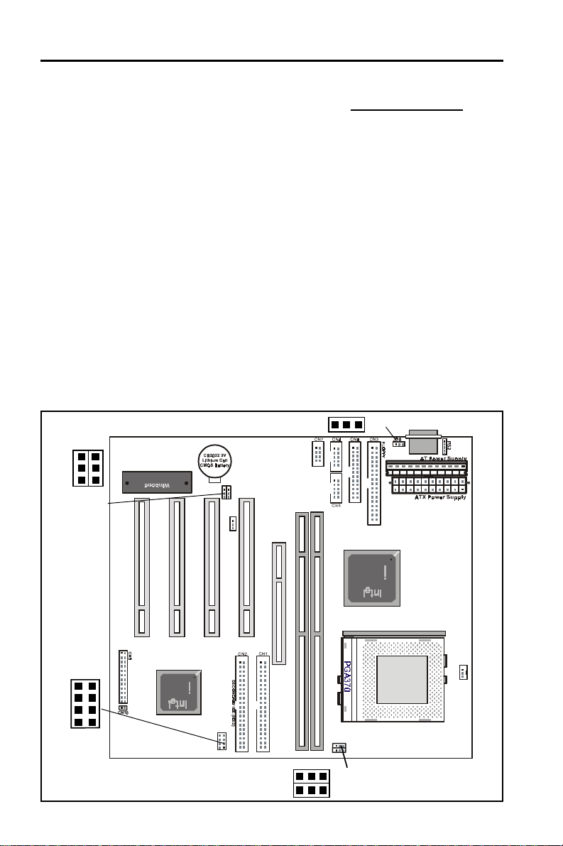
This section covers External Connectors and Memory Configuration. Please
refer to the motherboard layout chart for external connectors, slots and I/O
ports. Furthermore, this section lists all necessary connector pin assignments for your reference. The locations of the connectors and ports are illustrated in the following figures. Before inserting these connectors, please pay
attention to the orientations.
NOTICE !!!
1. Make sure to unplug your power supply while adding or removing
system components
2. Always work on an antistatic surface to avoid possible damage to the
motherboard or other components from static discharge.
2.2 Motherboard Layout
1
JP27
8
2
JP3
1
JP28
7
1
1
P
C
U
1
S
B
1
1
1
1
JP2
JP1
r
i
O
n
t
M
e
1
r
C
O
M
2
JJP2
P1
1
J
J
1
1
P
P
2
2
7
P
P
C
C
I
I
3
4
1
F
8
W
2
3
7
1
E
B
P
C
I
s
e
t
1
8
P
P
C
C
I
1
I
2
C
N
1
2
2
W
O
L
A
G
P
1
D
D
I
I
M
M
M
M
2
1
1
1
P
R
I
M
A
R
Y
I
D
E
(
I
D
E
1
)
8
7
J
P
3
2
1
1
1
JP9
1
X
4
B
4
3
e
t
AT KB C onnector
1
2
W
8
F
s
P
G
A
1
1
1
C
P
1
U
F
a
n
Page 4
Page 5
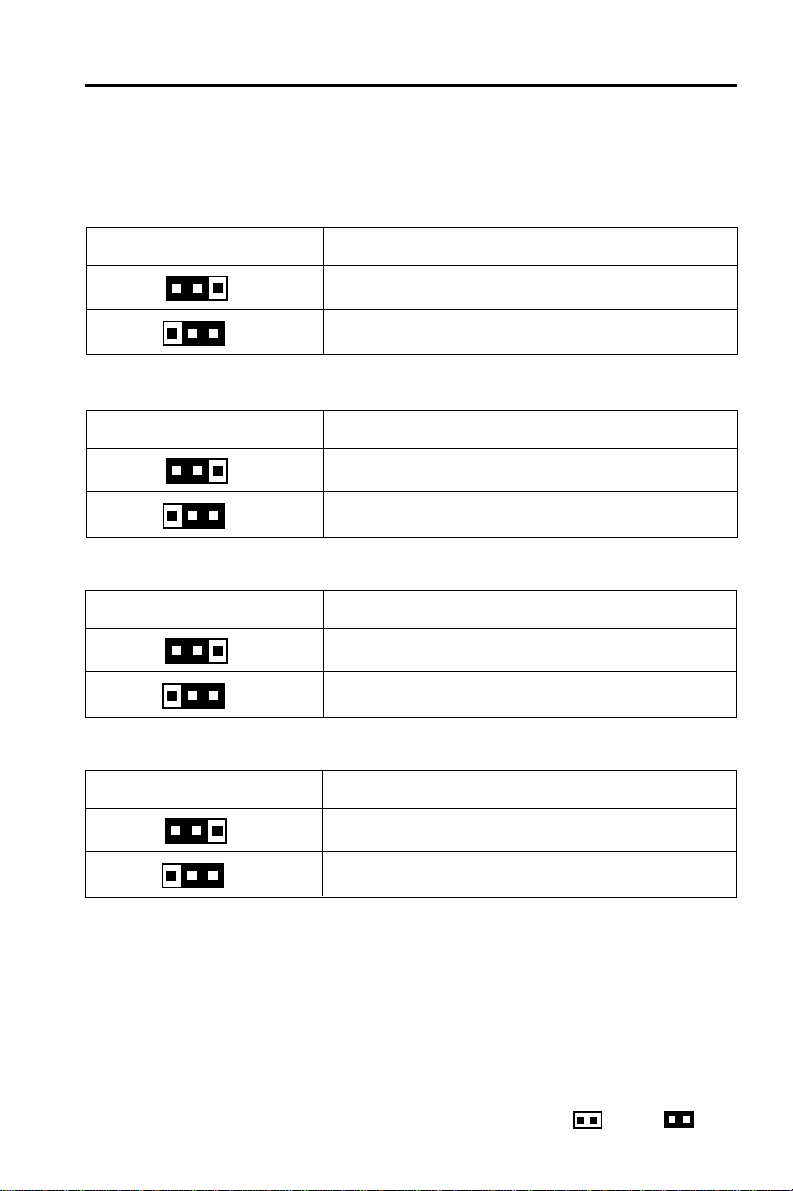
2.3 Jumper Setting
CPU Speed - JP1
JP1 CPU Speed
GC-2001 Motherboard
1
1
(1-2)
(2-3)
CPU Speed - JP2
JP2 CPU Speed
1
1
(1-2)
(2-3)
CPU Voltage - JP9
JP9 CPU Voltage
1
1
(1-2)
(2-3)
CMOS Clear - JP28
JP28 Function
1
(1-2)
100 MHz
66 MHz
100 MHz
133 MHz
VCC
5VSB
Normal (Default)
1
(2-3)
CMOS Clear
Remark: Open Close
Page 5
Page 6
GC-2001 Motherboard
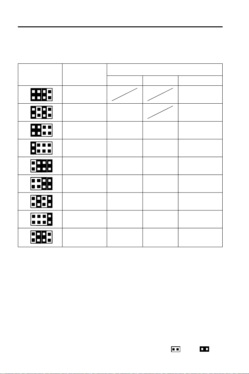
CPU Frequency Ratio selection - JP3
JP3 CPU Ratio
7
8
7
8
7
8
7
8
7
8
7
8
7
8
7
8
7
8
1
2
1
2
1
2
1
2
1
2
1
2
1
2
1
2
1
2
CPU Speed
66MHz 100MHz 133MHz
4.0 X 533MHz
4.5 X 300MHz 600MHz
5.0 X 333MHz 500MHz 667MHz
5.5 X 366MHz 550MHz 733MHz
6.0 X 400MHz 600MHz 800MHz
6.5 X 433MHz 650MHz 866MHz
7.0 X 466MHz 700MHz 933MHz
7.5 X 500MHz 750MHz 1000MHz
8.0 X 533MHz 800MHz 1066MHz
Page 6
Remark: Open Close
Page 7
GC-2001 Motherboard
2.4 Function & Installation Instructions
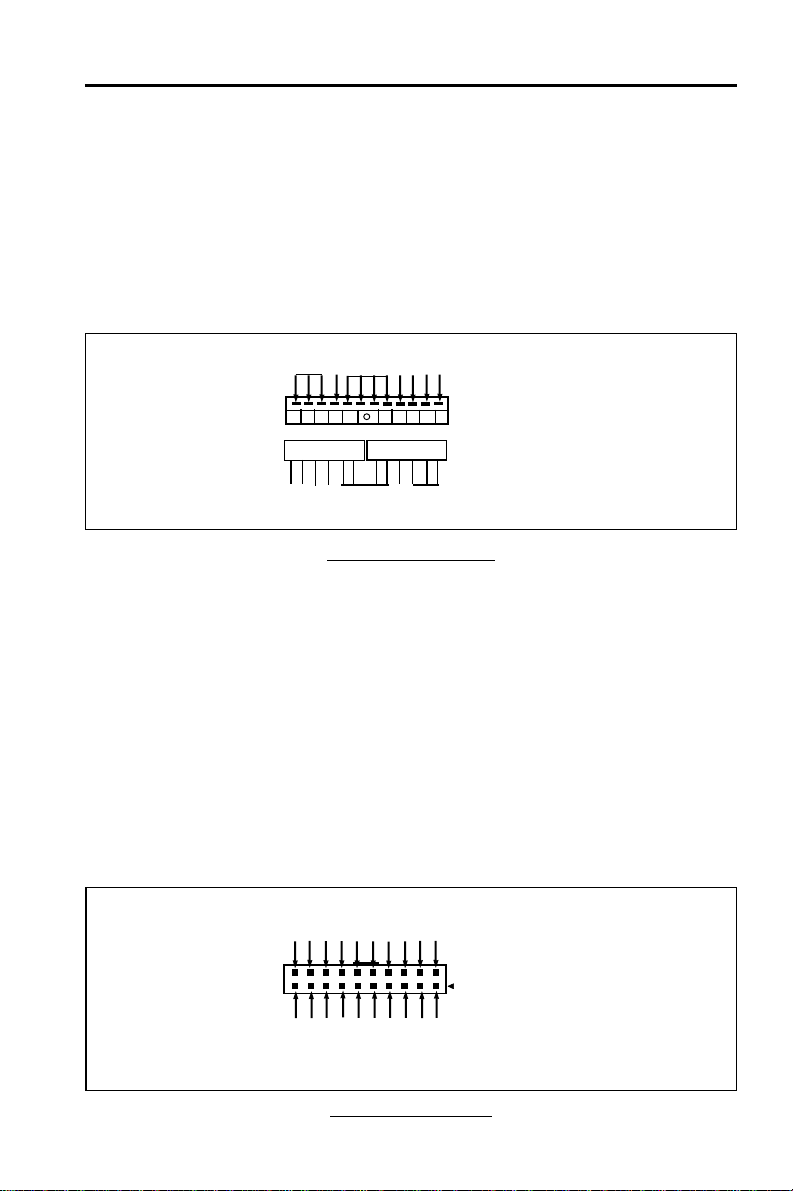
2.4.1 AT Power Supply Connector (12-Pin)
This connector connects to a standard 5V power supply. To connect the
leads from the power supply , ensure first that the power supply is not power
on. Most power supplies provide two plugs, and each plug contains six wires.
Two of six wires are black and please orient the plugs to the connector so
that 4 black wires are together.
Power Plug
Red
Orange
At a slight angle, align the plastic guide pins on the lead to their receptacles on the connector. Once aligned, press the lead onto the connector
until the lead locks into place.
Ground
+12V
-12V
Power Plug
Black
White
+5V
Red
PG
+5V
Yellow
-5V
Blue
AT Power Connector
Power
Connector on
Motherboard
Power Plugs
from Power
Supply
2.4.2 ATX Power Supply Connector (20-Pin)
This connector connects to an A TX power supply . The plug from A TX power
supply will only insert in one orientation because of the different hole sizes.
Find the proper orientation and push down firmly making sure that the pins
are aligned. The system power can be turned off through software control,
like the shut down in Windows 2000 / ME / 98 / 95 start menu. Power management must be enabled in the system BIOS in order to activate this softoff feature. Once the system BIOS receives the power management command from the OS, it will switch the system power off.
+5V
+5V
-5V
PWRGOOD
+5VSB
+12V
PW_ON
Ground
Ground
Ground
Ground
+5V
Ground
Ground
+5V
-12V
+3.3V
Ground
+3.3V
Power Connector on
Motherboard
+3.3V
ATX Power Connector
Page 7
Page 8
GC-2001 Motherboard
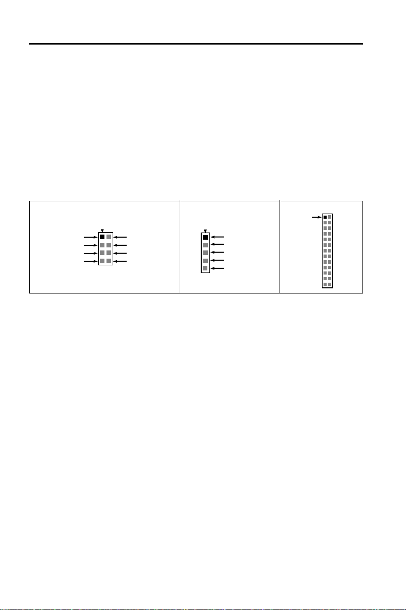
2.4.3 AT Keyboard Connector
This connector supports a standard IBM-compatible keyboard, such as 101/
102 enhanced keyboard (Use a PS/2 keyboard adapter in order to connect a
PS/2 KB to this A T connector.).
2.4.4 Serial (COM1/COM2) Port Connector
This motherboard provides two compatible serial ports, it can be used when
add additional serial devices.
2.4.5 USB Connector
This 8-pin connector connects to the optional USB ports cable with a
mounting bracket.
PRINTER
CN8- PS/2
1 MS-DATA
2NC
3GND
4 VCC
5 MS-CLK
1 USB-VCC
3 USB DT05 USB DT0+
7 USB-GND
CN7
2 USB-GND
4 USB DT1+
6 USB DT18 USB-VCC
2.4.6 PS/2 Connector
This 5-pin connector connects to the PS/2 ports cable with a mounting bracket.
2.4.7 Parallel Port Connector (26-pin)
This connector supports the included parallel port ribbon cable with mounting
bracket. Connect the parallel port ribbon cable to this connection and mount
the bracket to the case on an open slot, it will then be available for a parallel
printer cable.
Pin1
EXP ANSION CARDS INSTALLA TION
Before adding or removing any expansion cards or system components,
confirm that you already unplugged your power supply . Otherwise, it may
severely damage to your motherboard and expansion cards. Please follow the installation procedures as below:
1. Check carefully if those hardware or software settings for your expansion
cards are in the proper position as shown in their User’s Manual.
2. Remove your computer case’ s cover and unscrew the bracket plate for
those slots needed to insert.
3. Those expansion cards must be aligned on the slots firmly with good
connection.
4. Put on the computer case cover.
5. If needed, set up the BIOS configuration and install the required drivers for
your expansion cards.
Page 8
Page 9
GC-2001 Motherboard
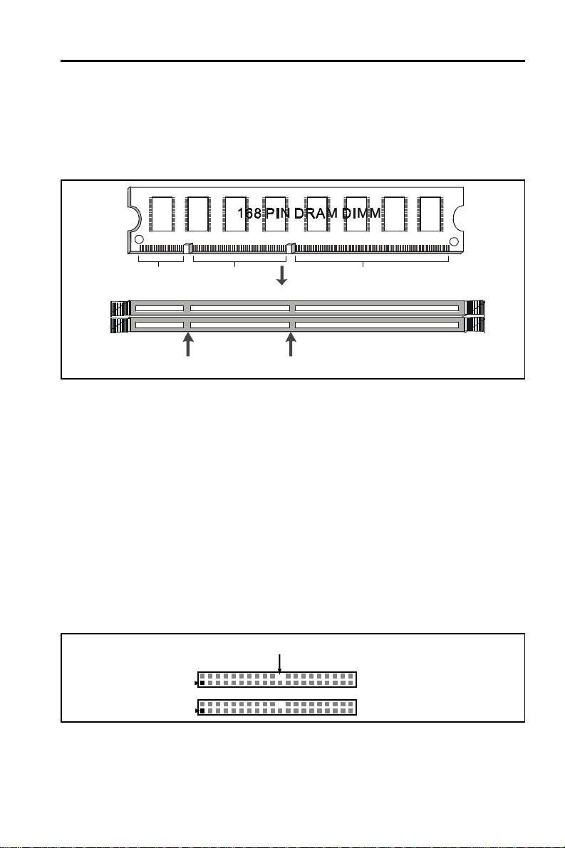
2.4.8 SDRAM Sockets
There are two SDRAM sockets on-board to provide more flexibility for your
system memory upgrade. Because the number of pins are different on either
side of the breaks, the DIMM module will only fit the 3.3V 168-pin unbuffered
for this motherboard.
20Pins 60Pins 88Pins
Lock
Two DIMM Socket
Unbuffered
DRAM Key
3.3V Key
168-Pin SDRAM Module Installation Diagram
2.4.9 Floppy Drive Connector (34-Pin)
This connector supports the provided floppy drive ribbon cable. After connecting the single end to the on-board “FLOPPY” connector, connect the
remaining plugs on the other end to the floppy drives correspondingly .
2.4.10 IDE Connectors (40-Pin)
The IDE connectors support the provided IDE HDD ribbon cable. After
connecting the single end to the board, connect the two plugs at the other
end to your HDDs. If you install two IDE devices on the same cable, you must
configure the second device to slave mode by setting its jumper accordingly .
(Refer to your IDE device document for the jumper settings. Pin 20 is removed to prevent inserting in the wrong orientation when using ribbon cables
with pin 20 plugged.)
Pin20 be removed
Primary IDE (IDE1)
Pin1
Secondary IDE (IDE2)
IDE Connectors
2.4.11 BIOS
The motherboard flash BIOS provides users with more flexibility in upgrading
their motherboards. The flash BIOS can be easily reprogrammed via software.
Page 9
Page 10
GC-2001 Motherboard
2.4.12 PCI Slots
This motherboard provides four full-length 32-bit PCI slots with up to 133MB/
sec burst data transfer rate.
2.4.13 AGP(Accelerated Graphics Port) Slot
This motherboard provides an AGP Slot to support AGP graphics cards
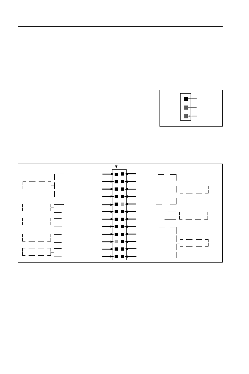
2.4.14 Wake-On-LAN Interface (WOL)
This connector connects to a LAN card with a
Wake-On-LAN output. The connector powers
up the system when a wakeup signal is received
from the network.
2.4.15 Front Panel Function Connector
The front panel integrates: 4-pin Speaker, 2-pin Reset Switch, 2-pin IDE LED,
2-pin Power Led, 2-pin Power On, 5-pin IrDA, 2-pin EXT SMI, 5-pin Keylock.
The connector pin out are described as the figure below:
1 Speaker 2 RX
SPEAKER
RESET
IDE LED
PW LED
PWR ON
3 NC 4 Ground
5 Ground 6 T X
7 VCC +5V 8 VCC
9 Reset 1 0 NC
11 Ground 12 EXT SMI
13 VCC 1 4 Ground
1 5 IDE LED 1 6 VCC
1 7 PW L ED 1 8 Ground
19 Ground 20 Ground
21 ATXPWRON 22 Keylock
23 Ground 24 Ground
CN22- WOL
1
+5VSB
WOL
GND
IrDA
EXT SMI
KEYLOCK
2.4.16 PGA370 CPU Socket
The motherboard provides a ZIF Socket 370. The CPU that comes with the
motherboard should have a fan attached to it to prevent overheating. If it is not
so, purchase a fan before you turn on your system.
Notice !!!
Be sure that there is a sufficient air circulation across the processor’s
heatsink by regularly checking that your CPU fan is working. Without
sufficient circulation, the processor could be overheated and it may damage both the processor and the motherboard. Y ou may install an auxiliary
fan, if necessary .
Page 10
Page 11
GC-2001 Motherboard
Installation step:
1.Turn off the power of your system and remove its cover;
2.Locate the ZIF socket and open it by first pulling the lever sideways away
from the socket then upwards to a 90-degree angle;
3.Insert the CPU with correct orientation
(The CPU has a corner pin for two of the four corners, that the CPU only fit
in the orientation.)
4.Once completely inserted, pull down the socket’s lever to horizontal and
make sure the CPU is firmly locked in the socket.
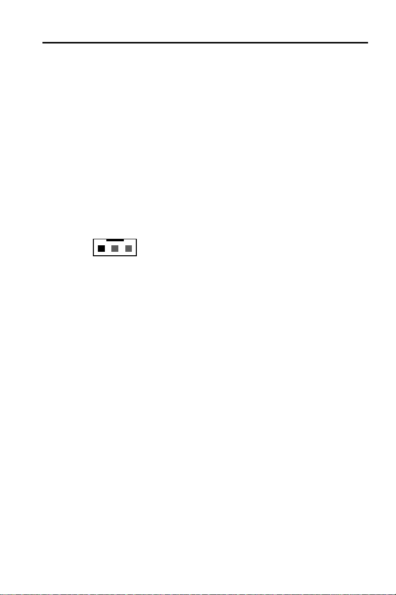
2.4.17 CPU Fan Connector
CPU Fan cable plug in the 3-pin CPU Fan connector onboard.
CN17- CPU FAN
1
Pin1 Sense
Pin2 +12V
Pin3 GND
Page 11
Page 12

GC-2001 Motherboard
Chapter 3
Software Installation
Note:
Before installation, you must already have Windows 95/98/
2000/ME or Windows NT4.0 install on your computer.
The installation procedure is as below:
1. Make sure that Auto-insert detection is enabled for your CDROM
drive. It should be enabled by default.
2. Insert this CD disk into your CDROM drive.
3. The Explorer screen will then appear, that gives you instructions
for installation.
4. There may require restarts of Windows during some software
setup. In these cases, you can just eject then close the CD-tray in
order to get back to the Explorer screen. You can then proceed
with the next step.
Y ou can get more information with open file:
disk.
Page 12
readme.txt
in the CD
Page 13
GC-2001 Motherboard
Chapter 4
AMIBIOS Setup
This GC-2001 motherboard comes with the AMI BIOS from AMI
Software Inc. Enter the AMI BIOS program Main Menu by:
1. Turn on or reboot the system. After a series of diagnostic checks,
the following message will appear:
Press <DEL> to enter setup, ESC to skip memory test
2. Press the <DEL> key and the main program screen will appear
as follows.
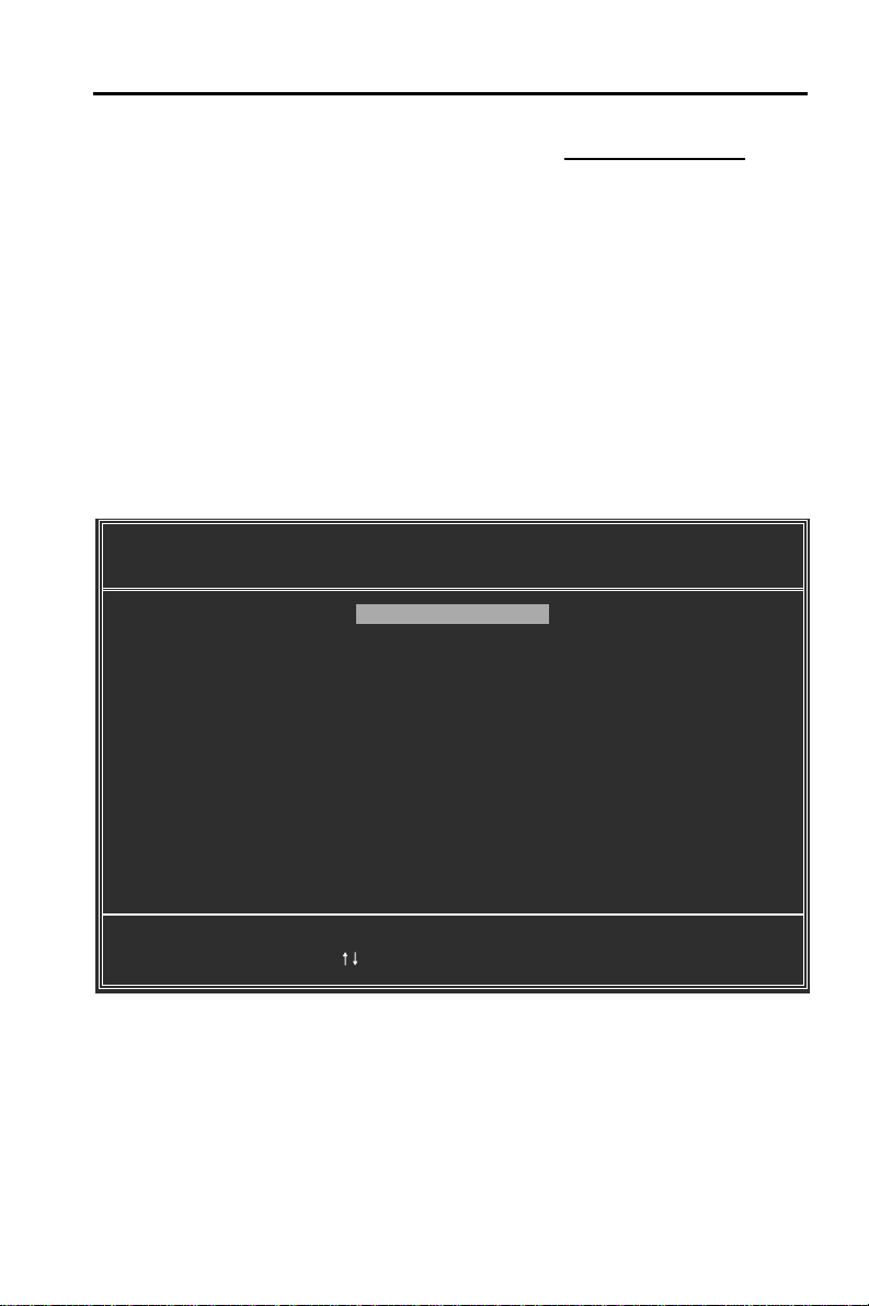
AMIBIOS HIFLEX SETUP UTILITY - VERSION 1.21
(C)1998 American Megatrends, Inc. All Rights Reserved
Standard CMOS Setup
Advanced CMOS Setup
Advanced Chipset Setup
Power Management Setup
PCI / Plug and Play Setup
Peripheral Setup
CPU Configuration Setup
Auto-Detect Hard Disks
Change User Password
Change Supervisor Password
Auto Configuration with Optimal Settings
Save Settings and Exit
Exit Without Saving
Standard CMOS setup for changing time, date, hard disk type, etc.
ESC:Exit :Sel F2/F3:Color F10:Save & Exit
Page 13
Page 14

GC-2001 Motherboard
3. Using the arrows on your keyboard, select an option, and
press <Enter>. Modify the system parameters to reflect the options
installed in your system. Otherwise you may return to the Main
Menu anytime by pressing <ESC> .
Types of Setup Description
Standard CMOS Setup Sets time, date, hard disk type, types of floppy
drives, monitor type, and if keyboard is installed.
Advanced CMOS Setup Sets Typematic Rate and Delay, Above 1MB
Memory Test, Memory Test Tick Sound, Hit
<Del> Message Display, System Boot Up Sequence, and others.
Advanced Chipset Setup Sets chipset-specific options and features.
Power Management Setup Controls power conservation options.
PCI/PnP Setup Sets options related to the PCI bus and Plug
and Play options.
Peripheral Setup Controls I/O Controller-related options.
CPU Configuration Setup This option selects the type of CPU install in the
motherboard. The settings are
automatically determines the CPU type)
Auto
(AMIBIOS
.
4. In the Main Menu, “Save Settings and Exit” saves your changes
and reboots the system, and “Exit Without Saving” ignores your
changes and exits the CMOS Setup.
Page 14
Page 15

GC-2001 Motherboard
AMIBIOS SETUP - STANDARD CMOS SETUP
(C)1998 American Megatrends, Inc. All Rights Reserved
Date (mm/dd/yyyy) : Tue Nov 21, 2000 Base Memory: 640 KB
Time (hh/mm/ss) : 16:17:06 Extd Memory: 127 MB
Floppy Drive A: 1.44 MB 3½
Floppy Drive B: Not Installed
Typ e Size Cyln Head WPcom Se c Mode Mode Mode Mode
Pri Master : Auto On
Pri Slave : Auto On
Sec Master : Auto On
Sec Slave : Auto On
Boot Sector Virus Protection Disabled
Available Options: ESC:Exit :Sel
Disabled PgUp/PgDn:Modify
Enabled F1:Help F2/F3:Color
LBA Blk PIO 32Bit
4.1 Standard CMOS Setup
Select the AMIBIOS Setup options by choosing Standard Setup from the
AMIBIOS Setup main menu. Standard Setup options are described below.
Floppy Drive A: and B:
Move the cursor to these fields via and and select the floppy type. The
settings are
inch
, or
Primary Master
Primary Slave
Secondary Master
Secondary Slave
Select these options to configure the drive named in the option. Select
Auto Detect IDE
with a list of drive parameters appears. Click on OK to configure the drive.
360 KB 5¼ inch, 1.2 MB 5¼ inch, 720 KB 3½ inch, 1.44 MB 3½
2.88 MB 3½ inch.
to let AMIBIOS automatically configure the drive. A screen
Page 15
Page 16

GC-2001 Motherboard
T ype How to Configure
SCSI Select
IDE Select
CD-ROM Select
Standard MFM Select
Non-Standard Select
MFM parameters listed for drive types 1-46, select
Entering Drive Parameters
Y ou can also enter the hard disk drive parameters. The drive parameters are
Parameter Description
Type The number for a drive with certain identification parameters.
Cylinders The number of cylinders in the disk drive.
Heads The number of heads.
Write The actual physical size of a sector gets progressively smaller as
Precomp- the track diameter diminishes. Yet each sector must still hold
ensation 512 bytes. Write precompensation circuitry on the hard disk
Landing Zone This number is the cylinder location where the heads normally
Sectors
Capacity The formatted capacity of the drive is the number of heads times
Type
. Select
The SCSI drivers provided by the SCSI manufacturer should
allow you to configure the SCSI drive.
Type.
Select
eters. Click on OK when AMIBIOS displays the drive parameters. Select
pacity greater than 540 MB. Select
allow block mode data transfers. Select
On
to allow 32-bit data transfers. Select the
to select
you select a PIO mode that is not supported by the IDE drive, the
drive will not work properly. If you are absolutely certain that you
know the drive’s PIO mode, select PIO mode 0-5, as appropriate.
plays the drive parameters.
drive type that exactly matches your drive’s parameters.
Auto
Type
. Select
Type.
You must know the drive parameters. Select the
Type.
correct hard disk drive parameters.
compensates for the physical difference in sector size by boosting the write current for sectors on inner tracks. This parameter
is the track number on the disk surface where write
precompensation begins.
park when the system is shut down.
The number of sectors per track. MFM drives have 17 sectors per track.
RLL drives have 26 sectors per track. ESDI drives have 34 sectors
per track. SCSI and IDE drives have even more sectors per track.
the number of cylinders times the number of sectors per track
times 512 (bytes per sector).
Not Installed
Auto
to let AMIBIOS determine the param-
LBA/Large Mode
to allow AMIBIOS to determine the PIO mode. If
CDROM
If the drive parameters do not match the drive
Page 16
the drive parameter screen.
. Select On if the drive has a ca-
Block Mode
32-Bit Transfer
. Click on OK when AMIBIOS dis-
. Select On to
PIO Mode
User
and enter the
. Select
. It is best
Page 17

GC-2001 Motherboard
4.2 Advanced CMOS Setup
The AMIBIOS Setup options described in this section are selected
by choosing Advanced CMOS Setup from the AMIBIOS Setup main
menu.
4.3 Advanced Chipset Setup
Choose Chipset Setup on the AMIBIOS Setup main menu. All Chipset
Setup options are then displayed. AMIBIOS Setup can be customized.
4.4 Power Management Setup
The AMIBIOS Setup options described in this section are selected
by choosing Power Management Setup from the AMIBIOS Setup
main menu.
4.5 PCI / PnP Setup
Choose PCI/Plug and Play Setup from the AMIBIOS Setup screen
to display the PCI and Plug and Play Setup options.
4.6 CPU Configuration Setup
This system BIOS is capable to detect the CPU type, say Pentium III,
Pentium II or Celeron. The user is only required to select the CPU
speed. In addition, overclocking option is provided for advanced
users who prefer to run the CPU over the specified clock frequency .
4.7 Save Settings and Exit
Choose Save Setting and Exit from the AMIBIOS Setup main menu.
Type “Y” to exit the BIOS Setup program and saving the values.
Type “N” to return to the Setup program.
4.8 Exit Without Saving
Choose Exit Without Saving from the AMIBIOS Setup main menu.
Type “Y” to exit the BIOS Setup program without saving the values.
Type “N” to return to the Setup program.
The End
Page 17
 Loading...