

Champion HRA20-12, HRA25-25, HRA20-25, HRA30-12, HRA25-12 Operation & Maintenance Manual
...
A
A
(
g)
OPERATION/MAINTENANCE
MANUAL & PARTS LIST
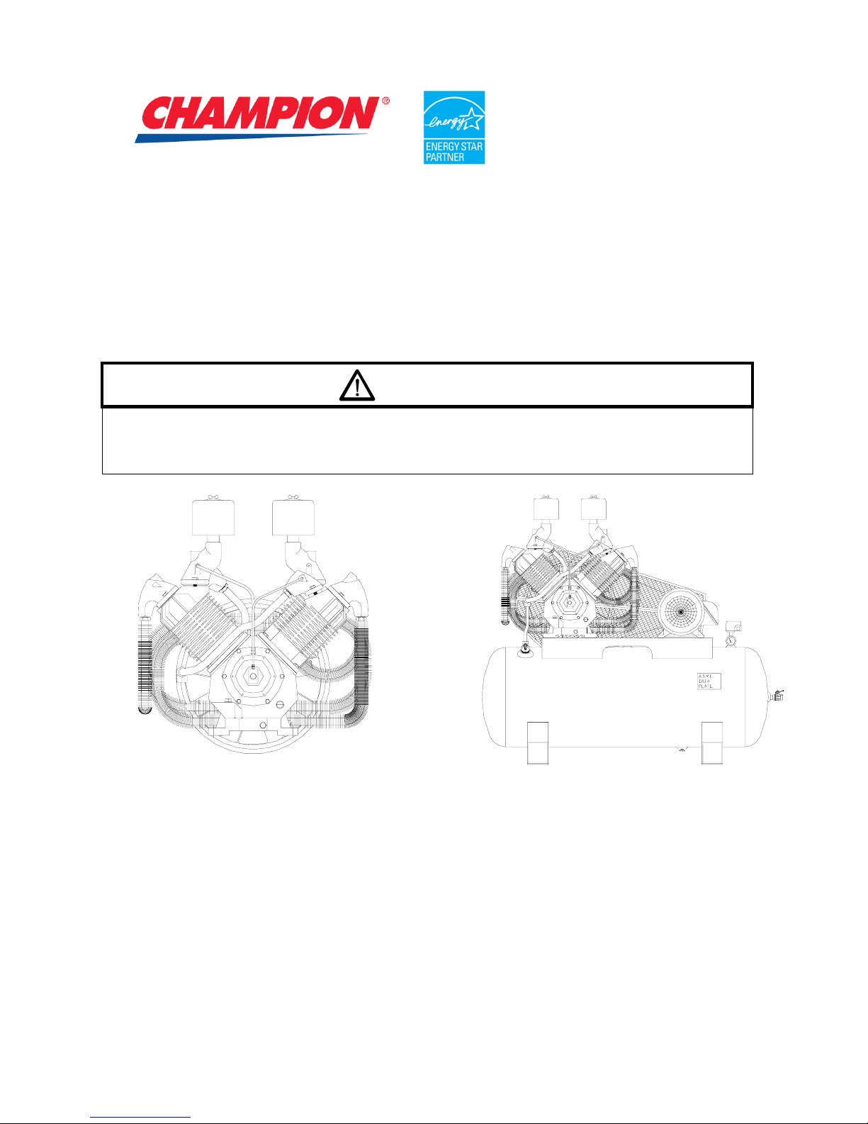
TWO STAGE/FOUR CYLINDER R70A
AIR COMPRESSOR & UNITS
WARNING
THIS MANUAL CONTAINS IMPORTANT SAFETY INFORMATION AND SHOULD ALWAYS BE
AVAILABLE TO THOSE PERSONNEL OPERATING THIS UNIT.
READ, UNDERSTAND AND RETAIN ALL INSTRUCTIONS BEFORE OPERATING THIS
EQUIPMENT TO PREVENT INJURY OR EQUIPMENT DAMAGE.
MODEL R70A COMPRESSOR MODEL HRA25-12 UNIT
Form No. F3234 VER: 09 07/01/2009
C324-
Ref. Drawin
C469(Ref. Drawing)

MAINTAIN COMPRESSOR RELIABILITY AND PERFORMANCE WITH
GENUINE CHAMPION COMPRESSOR
PARTS AND SUPPORT SERVICES
Champion
Compressor genuine parts, manufactured to design tolerances, are developed for optimum
dependability – specifically for Champion compressor systems. Design and material innovations are the
result of years of experience with hundreds of different compressor applications. Reliability in materials
and quality assurance are incorporated in our genuine replacement parts.
Your authorized Champion Compressor distributor offers all the backup you’ll need. A worldwide network
of authorized distributors provides the finest product support in the air compressor industry.
Your authorized distributor can support your Champion air compressor with these services:
1. Trained parts specialists to assist you in selecting the correct replacement parts.
2. A full line of factory tested CHAMPLUB™ compressor lubricants specifically formulated for use in
Champion compressors.
3. Repair and maintenance kits designed with the necessary parts to simplify servicing your
compressor.
Authorized distributor service technicians are factory trained and skilled in compressor maintenance and
repair. They are ready to respond and assist you by providing fast, expert maintenance and repair
services.
For the location of your local authorized Champion Air Compressor distributor, refer to the yellow
pages of your phone directory or contact:
Factory:
Champion
1301 North Euclid Avenue
Princeton, IL 61356
Phone: (815) 875-3321
Fax: (815) 872-0421
E-Mail: Champion@Championpneumatic.com
INSTRUCTIONS FOR ORDERING REPAIR PARTS
When ordering parts, specify Compressor MODEL, HORSEPOWER and SERIAL NUMBER (see
nameplate on unit). All orders for Parts should be placed with the nearest authorized distributor.
Order by part number and description. Reference numbers are for your convenience only.
2

TABLE OF CONTENTS
_______________________________________________________
Subject Page
Maintain Compressor Reliability And Performance With ...................................................................... 2
Safety And Operation Precautions........................................................................................................ 4
Explanation Of Safety Instruction Symbols And Decals ....................................................................... 5
Introduction ...........................................................................................................................................6
Warranty................................................................................................................................................ 6
Dimensions And Specifications............................................................................................................. 7
Installation .................................................................................................................................8, 9 & 10
Operation.............................................................................................................................................11
Maintenance......................................................................................................................... 12, 13 & 14
Compressor Pilot Valve Differential Pressure Adjustment.................................................................. 15
Compressor Oil Specifications ............................................................................................................16
Torque Valves ..................................................................................................................................... 16
Trouble Shooting Guide ..............................................................................................................17 & 18
Unit Repair Parts List ..............................................................................................................19 thru 21
Compressor Repair Parts List.................................................................................................22 thru 25
Constant Speed Head Unloader ......................................................................................................... 26
Unit Hazard Decal Listing....................................................................................................................27
Unit Hazard Decals .............................................................................................................................28
Pump Hazard Decals .......................................................................................................................... 28
Record Of Maintenance Service .......................................................................................... 29, 30 & 31
3

SAFETY AND OPERATION PRECAUTIONS
___________________________________________________________________________________
Because an air compressor is a piece of machinery with moving and rotating parts, the same precautions
should be observed as with any piece of machinery of this type where carelessness in operation or
maintenance is hazardous to personnel. In addition to the many obvious safety rules that should be
followed with this type of machinery, the additional safety precautions as listed below must be observed:
1. Read all instructions completely before operating air compressor or unit.
2. For installation, follow all local electrical and safety codes, as well as the National Electrical Code
(NEC) and the Occupational Safety and Health Act (OSHA).
3. Electric motors must be securely and adequately grounded. This can be accomplished by wiring
with a grounded, metal-clad raceway system to the starter; by using a separate ground wire
connected to the bare metal of the motor frame; or other suitable means.
4. Protect the power cable from coming in contact with sharp objects. Do not kink power cable and
never allow the cable to come in contact with oil, grease, hot surfaces, or chemicals.
5. Make certain that the power source conforms to the requirements of your equipment.
6. Pull main electrical disconnect switch and disconnect any separate control lines, if used, before
attempting to work or perform maintenance on the air compressor or unit. "Tag Out" or "Lock Out"
all power sources.
7. Do not attempt to remove any compressor parts without first relieving the entire system of
pressure.
8. Do not attempt to service any part while machine is in an operational mode.
9. Do not operate the compressor at pressures in excess of its rating.
10. Do not operate compressor at speeds in excess of its rating.
11. Periodically check all safety devices for proper operation. Do not change pressure setting or
restrict operation in any way.
12. Be sure no tools, or rags or loose parts are left on the compressor or drive parts.
13. Do not use flammable solvents for cleaning the air inlet filter or element and other parts.
14. Exercise cleanliness during maintenance and when making repairs. Keep dirt away from parts by
covering parts and exposed openings with clean cloth or Kraft paper.
15. Do not operate the compressor without guards, shields and screens in place.
16. Do not install a shut-off valve in the discharge line, unless a pressure relief valve, of proper design
and size, is installed in the line between the compressor unit and shut-off valve.
17. Do not operate compressor in areas where there is a possibility of ingesting flammable or toxic
fumes.
18. Be careful when touching the exterior of a recently run motor - it may be hot enough to be painful
or cause injury. With modern motors this condition is normal if operated at rated load - modern
motors are built to operate at higher temperatures.
19. Inspect unit daily to observe and correct any unsafe operating conditions found.
20. Do not "play around" with compressed air, nor direct air stream at body, because this can cause
injuries.
21. Compressed air from this machine absolutely must not be used for food processing or breathing
air without adequate downstream filters, purifiers and controls.
22. Always use an air pressure regulating device at the point of use, and do not use air pressure
greater than marked maximum pressure of attachment.
23. Check hoses for weak or worn condition before each use and make certain that all connections
are secure.
24. Always wear safety glasses when using a compressed air blow gun.
The user of any air compressor package manufactured by Champion is hereby warned that failure to
follow the preceding Safety and Operation Precautions can result in injuries or equipment damage.
However, Champion does not state as fact or does not mean to imply that the preceding list of Safety and
Operating Precautions is all inclusive, and further that the observance of this list will prevent all injuries or
equipment damage.
4
EXPLANATION OF SAFETY INSTRUCTION SYMBOLS AND DECALS
DANGER
Indicates immediate hazards which will result in severe injury or death.
WARNING
Indicates hazards or unsafe practice which could result in severe injury or death.
CAUTION
Indicates hazards or unsafe practice which could result in damage to the Champion
compressor or minor injury.
NOTICE
Notice is used to notify people of installation, operation or maintenance information which is
important but not hazard-related.
SAFETY AND OPERATION PRECAUTIONS
OBSERVE, UNDERSTAND AND RETAIN THE INFORMATION GIVEN IN THE SAFETY
PRECAUTION DECALS AS SHOWN IN THE PARTS LIST SECTION
DANGER
This reciprocating compressor must not be used for breathing air. To do so will cause serious
injury whether air is supplied direct from the compressor source or to breathing tanks for later
use. Any and all liabilities for damage or loss due to injury, death and/or property damage
including consequential damages stemming from the use of this compressor to supply
breathing air, will be disclaimed by the manufacturer.
WARNING
The use of this compressor as a booster pump and/or to compress a medium other than
atmospheric air is strictly non-approved and can result in equipment damage and/or injury.
CAUTION
This unit may be equipped with special options which may not be included in this manual. User
must read, understand and retain all information sent with special options.
5

INTRODUCTION
______________________________________________________________________
Champion R Series compressors are the result of advanced engineering and skilled manufacturing. To
be assured of receiving maximum service from this machine the owner must exercise care in its operation
and maintenance. This book is written to give the operator and maintenance department essential
information for day-to-day operation, maintenance and adjustment. Careful adherence to these
instructions will result in economical operation and minimum downtime.
WARRANTY
Champion Five Year Warranty
"R" Series Compressors
CHAMPION warrants each new compressor pump manufactured by CHAMPION, mounted on a factory
assembled unit, to be free from defects in material and workmanship under normal use and service for a
period of sixty (60) months from date of installation or sixty-six (66) months from date of shipment by
CHAMPION or CHAMPION distributor, whichever may occur first. Applies to the compressor pump
only
, excluding head valves. Valves, controls and accessories are warranted for the first year only.
Compressor pumps purchased separately would carry a one year warranty.
This five year extended warranty will be prorated over the 5 years as follows:
First Year - 100% Allowance, Parts and Labor
Second Year - 90% Allowance, Parts and Labor
Third Year - 80% Allowance, Parts and Labor
Fourth Year - 70% Allowance, Parts and Labor
Applies to CHAMPION logo, tank or base mounted complete compressors only.
Fifth Year - 60% Allowance, Parts and Labor
Express Limited Warranty
CHAMPION warrants each new air compressor unit manufactured by CHAMPION to be free from defects
in material and workmanship under normal use and service for a period of twelve (12) months from date of
installation or eighteen (18) months from date of shipment by CHAMPION or CHAMPION distributor,
whichever may occur first.
CHAMPION makes no warranty in respect to components and accessories furnished to CHAMPION by
third parties, such as ELECTRIC MOTORS, GASOLINE ENGINES and CONTROLS, which are warranted
only to the extent of the original manufacturer's warranty to CHAMPION. To have warranty consideration,
electric motors must be equipped with thermal overload protection.
The extended five year warranty will apply to ASME air receivers provided they are installed on rubber
vibro isolator pads or approved equivalent.
When a compressor pump, or component is changed or replaced during the warranty period, the
new/replaced item is warranted for only the remainder of the original warranty period.
Repair, replacement or refund in the manner and within the time provided shall constitute CHAMPION'S
sole liability and your exclusive remedy resulting from any nonconformity or defect. CHAMPION SHALL
NOT IN ANY EVENT BE LIABLE FOR ANY DAMAGES, WHETHER BASED ON CONTRACT,
WARRANTY, NEGLIGENCE, STRICT LIABILITY OR OTHERWISE, INCLUDING WITHOUT LIMITATION
ANY CONSEQUENTIAL, INCIDENTAL OR SPECIAL DAMAGES, ARISING WITH RESPECT TO THE
EQUIPMENT OR ITS FAILURE TO OPERATE, EVEN IF CHAMPION HAS BEEN ADVISED OF THE
POSSIBILITY THEREOF.
CHAMPION MAKES NO OTHER WARRANTY OR REPRESENTATION OF ANY KIND, EXCEPT THAT
OF TITLE, AND ALL OTHER WARRANTIES, EXPRESS OR IMPLIED, INCLUDING WARRANTIES OR
MERCHANTABILITY AND FITNESS FOR A PARTICULAR PURPOSE, ARE HEREBY EXPRESSLY
DISCLAIMED. NO SALESMAN OR OTHER REPRESENTATIVE OF CHAMPION HAS AUTHORITY TO
MAKE ANY WARRANTIES
6
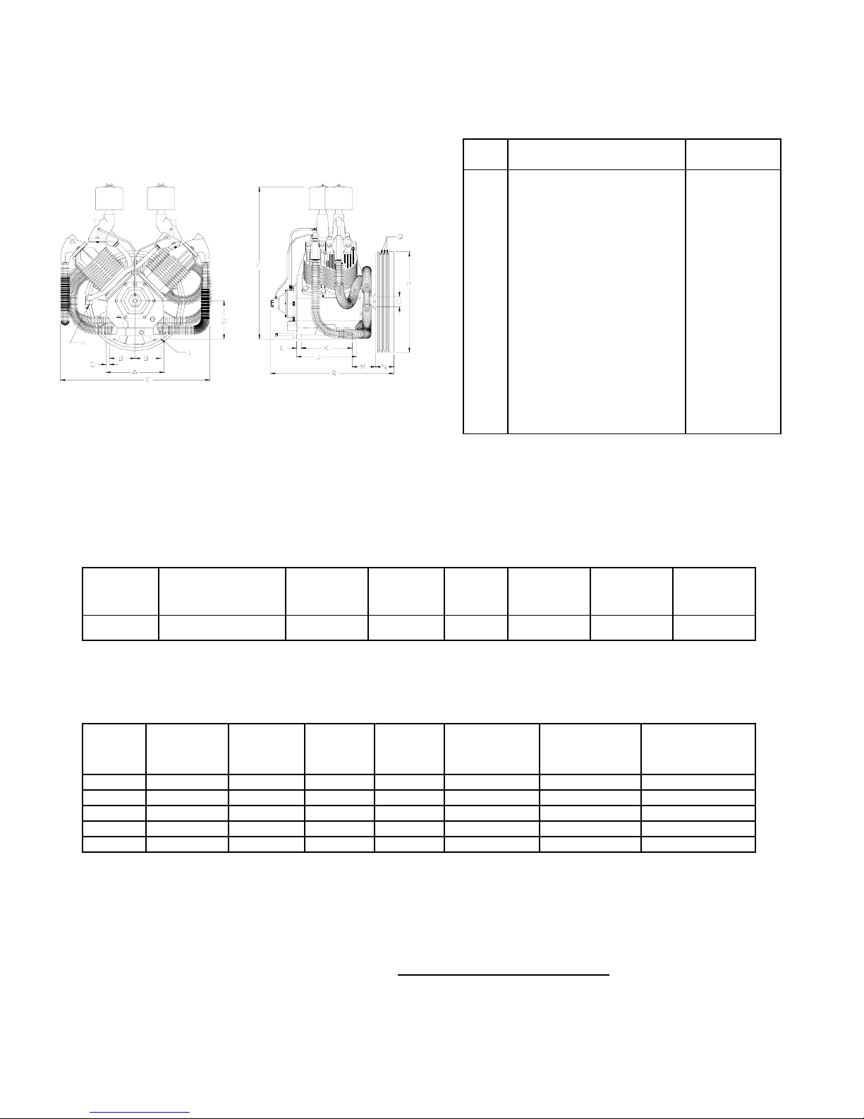
TWO STAGE AIR COMPRESSORS - MODEL R70A
DIMENSIONS
A
Base-Width
B
Bolt Down-Width
(from center line)
C
Bolt Down to Edge
D
Base to Crank Ctr
E
Overall Width
F
Overall Height
H
HP Exhaust Opening
I
Bolt Down Hole Dia.
J
Base-Depth
K
Bolt Down Depth
L
Bolt Down to Edge
M
Bolt Hole to Wheel (Max.)
N
Flywheel Width
O
Crank Diameter
P
Flywheel Diameter
Q
C-325-A
(Ref. Drawing)
NOTE:
Flywheel Rotation – Clockwise when viewed
from front, flywheel to rear.
SPECIFICATIONS
MODEL BORE & STROKE
(INCH)
NO. of
CYLINDERS
OIL
CAPACITY
(QTS)
WEIGHT
(LBS)
Flywheel Grooves
R
Overall Depth
MAXIMUM
PRESSURE
(PSIG)
ITEM PL70A
1-1/4NPT
CU
FT./REV.
MIN./MAX.
RPM.
12-7/8”
5-11/16”
3/4”
8-3/16”
33”
33-9/16”
9/16”
13-1/4”
11-1/4”
1”
5-3/4”
3-1/2”
2-1/4”
22”
3VB
27-1/4”
R70A 6-1/4" & 3-1/4" x 4" 4 6-1/3 450 175 .142 425/1000
PERFORMANCE
PUMP
R70A 125 20 770 109.4 2580 44,700 8.95
R70A 125 25 890 127.8 2980 55,970 11.4
R70A 175 20 665 93.0 2195 44,700 8.35
R70A 175 25 770 109.4 2580 55,970 9.75
R70A 175 30 890 127.8 2980 67,160 11.4
OUTPUT
PRESS.
PSIG
MOTOR
H.P.
PUMP
RPM
DISPL.
CFM
COOLING
AIR FLOW
CFM
HEAT
REJECTION
BTU/HR
APPROX.
PULLEY O.D.,
INCHES
All data is based on 1725 RPM electric motors as a power source.
Pulley Dia. (approx.) = Compressor RPM x Flywheel Dia.
Motor or Engine RPM
7
INSTALLATION
WARNING
Do not operate unit if damaged during shipping, handling or use. Operating unit if damaged
may result in injury.
1. Permanently installed compressors must be located in a clean, well ventilated dry room so
compressor receives adequate supply of fresh, clean, cool and dry air. It is recommended that a
compressor, used for painting, be located in a separate room from that area wherein body sanding
and painting is done. Abrasive particles or paint, found to have clogged the air intake filters and
intake valves, shall automatically void warranty.
2. Compressors should never be located so close to a wall or other obstruction that flow of air
through the fan blade flywheel, which cools the compressor, is impeded. Permanently mounted
units should have flywheel at least 12" from wall.
3. Place stationary compressors on firm level ground or flooring. Permanent installations require
bolting to floor. Bolt holes in tank or base feet are provided. Before bolting or lagging down, shim
compressor level. Avoid putting a stress on a tank foot by pulling it down to floor. This will only
result in abnormal vibration, and possible cracking of air receiver. It is recommended that unit be
set on optional vibro-isolator pads. Tanks bolted directly to a concrete floor without isolators will
not be warranted against cracking. Champion vibro-isolators or approved equivalent must be
installed for extended warranty to apply to ASME receivers.
4. If installing a bare pump, or base mounted unit, make certain the pressure limiting controls are
properly installed and operational. A pressure switch must be provided by customer for start/stop
operation. If a pilot valve is used the compressor must be equipped with head unloaders.
5. A properly sized air check valve must be installed in the discharge piping between the compressor
outlet and the inlet of any receiver tank(s) in the system.
DANGER
Do not install isolating valves between compressor outlet and air receiver. This will cause excessive
pressure if valve is closed and cause injury and equipment damage.
WARNING
Always use an air pressure regulating device at the point of use. Failure to do so can result in injury or
equipment damage.
CAUTION
• Do not install in an area where ambient temperature is below 32 degrees F or above
100 degrees F.
• Do not install unit in an area where air is dirty and/or chemical laden.
• Unit is not to be installed outdoors.
8
(0)4 (1)8 (6)
(
)
)6 (4)8 (6)
(
)
)
)8 (4)
INSTALLATION (CONT’D)
ELECTRICAL POWER SUPPLY
It is essential that the power supply and the supply wiring are adequately sized and that the voltage
correspond to the unit specifications. Branch circuit protection must be provided at installation a
specified in the National Electrical Code.
All wiring should be performed by a licensed electrician or electrical contractor. Wiring must meet
applicable codes for area of installation. The table gives recommended wire sizes based on the
1999 NEC.
WIRE SIZE (AWG) – 75°C COPPER – 30°C AMBIENT
3 PHASEMOTOR
HP
20 3
25 1
30 0
Values in ( ) for Duplex Unit w/one incoming power line to both motors.
200/208V 230V 460V 575V
10 (6)
000
0000
2 (00
1 (000
6 (3
All models require a properly sized magnetic starter as specified in the National Electric Code (NEC).
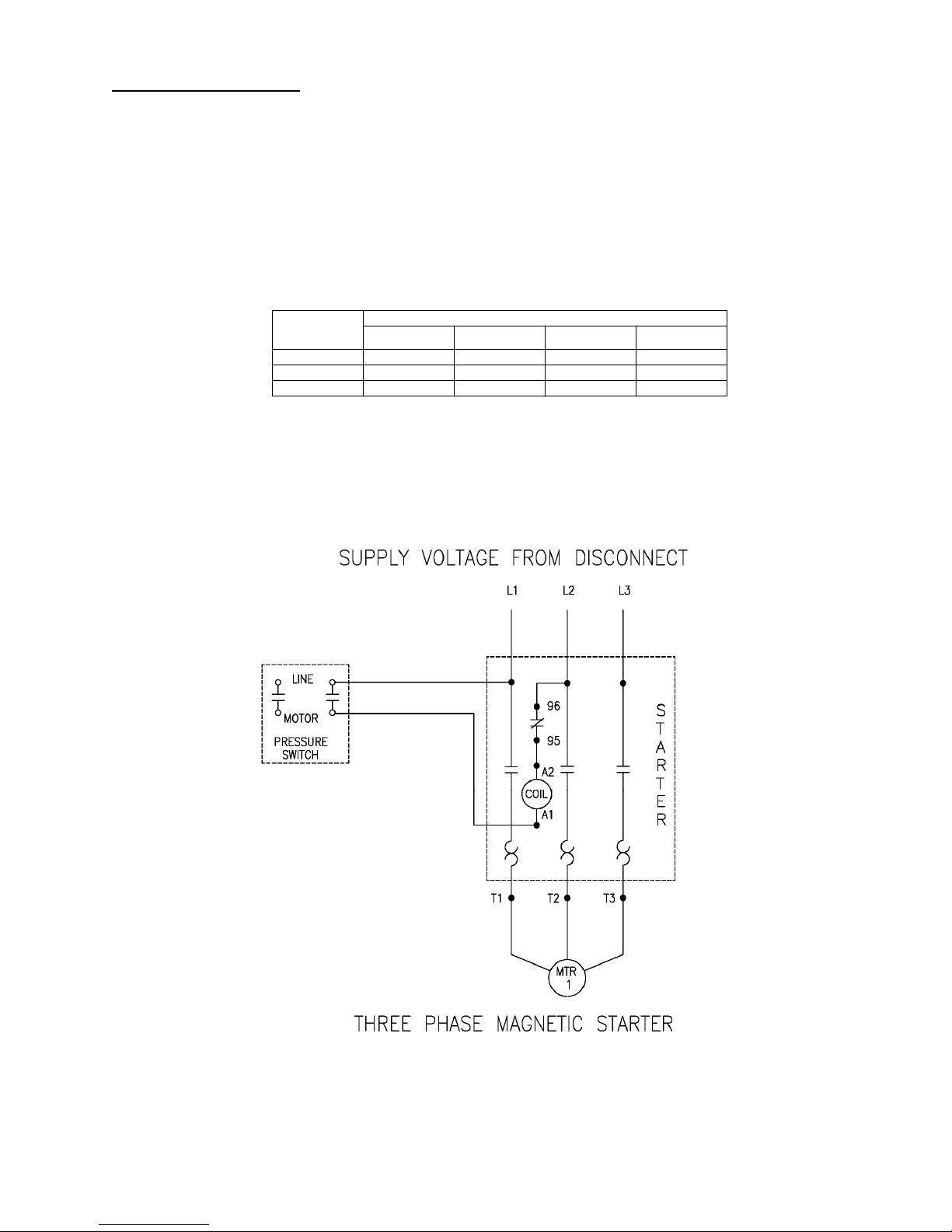
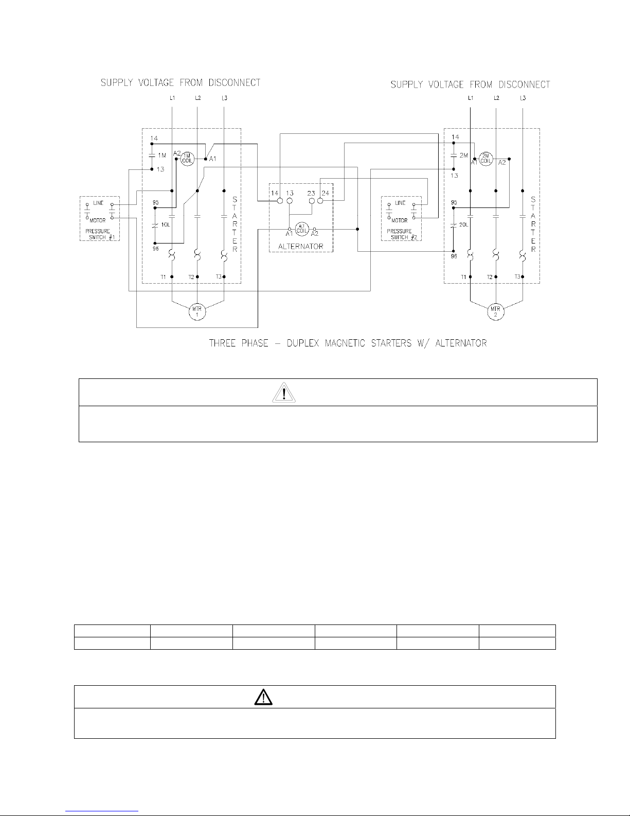
See Figure 1-1 for simplex wiring diagram and Figure 1-2 for duplex wiring diagram.
If ordered with a factory mounted magnetic starter, compressor is wired at factory. It is necessary only to
bring lines from a properly sized disconnect switch to the magnetic starter mounted on the unit.
304CAS546-A
(Ref. Drawing)
Figure 1-1 Simplex Wiring Diagram
9
ELECTRICAL POWER SUPPLY (CONT’D)
Figure 1-2 Duplex Wiring Diagram
312CAD546-B
(Ref. Drawing)
CAUTION
Wiring must be such that when viewing compressor from opposite shaft end, rotation of shaft is
clockwise as shown by arrow on guard. Wrong direction rotation for any length of time will result in
damage to compressor.
GROUNDING INSTRUCTIONS
AIR LINE PIPING
This product should be connected to a grounded, metallic, permanent wiring system, or an
equipment-grounding terminal or lead on the product.
Connection to air system should be of the same size, or larger, than discharge pipe out of unit.
The table gives recommended minimum pipe sizes. A union connection to the unit and water
drop leg is recommended. Install a flexible connector between the discharge of the unit and the
plant air piping. Plant air piping should be periodically inspected for leaks using a soap and water
solution for detection on all pipe joints. Air leaks waste energy and are expensive.
Minimum Pipe Sizes For Compressor Air Lines
(Based on clean Smooth Schedule 40 Pipe)
MODEL 25’ 50’ 100’ 200’ 300’
R70A 1-1/4” (1-1/2”) 1-1/4” (1-1/2”) 1-1/4” (1-1/2”) 1-1/2” (2”) 1-1/2” (2”)
Values in ( ) are for duplex unit.
Never use plastic pipe or improperly rated metal pipe. Improper piping material can burst and
cause injury or property damage.
WARNING
10
 Loading...