

Page 1
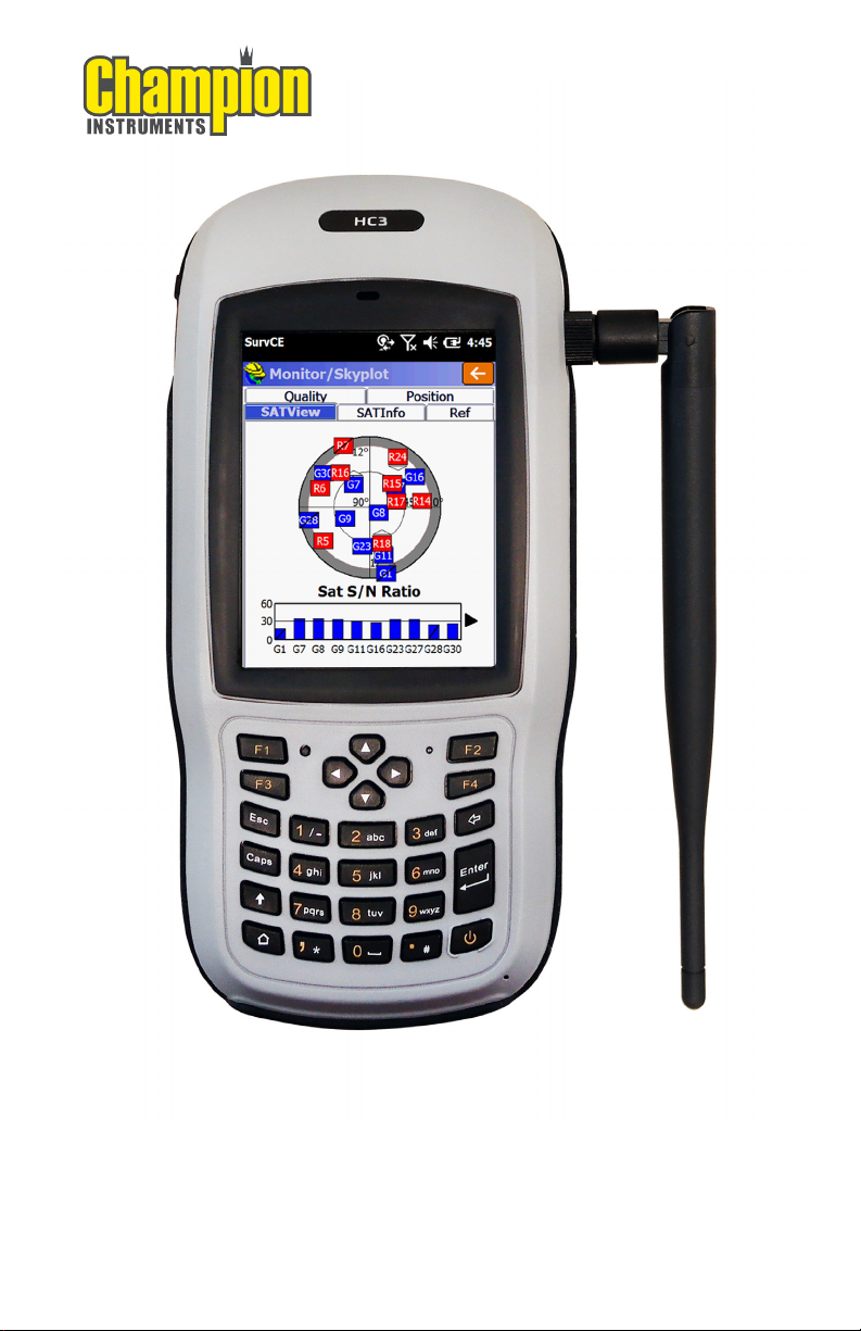
HC3 Ultimate Data Collector
Quick Start Guide
Page 2

1. Appearance
Table of Contents
1.1. General Diagram...............................................
1.2. Keyboard...........................................................
1.3. LED....................................................................
2. Operating Instructions
2.1. Installing the TF Card/SIM Card/Battery...........
2.2. Charging............................................................
2.3. Turning the Collector On/Off............................
2.4. Connecting to a PC...........................................
2.5. Installing SurvCE................................................
2.6. GNSS Status......................................................
2.7. Camera..............................................................
2.8. 9 Pin Serial Port.................................................
2.9. Wireless Connection (Bluetooth/GPRS/WiFi)
2.9.1. Standard Bluetooth.............................
2.9.2. Long Range Bluetooth........................
2.9.3. WiFi.....................................................
2.9.4. GPRS/3G Data Connection.................
3
3
5
5
6
6
7
7
11
12
12
12
12
14
14
3. Useful Functions
3.1. Screen Response...............................................
3.2. Adjusting the Backlight.....................................
3.3. Removing Programs..........................................
3.4. Auto Power Off*................................................
3.5. Clean Boot.........................................................
3.6. PWConfig...........................................................
4. Accessories
4.1. Standard Accessories........................................
4.2. Optional Accessories........................................
1
14
14
15
15
15
15
16
16
Page 3

5. Environmental Specifications......................................
17
6. Warranty Terms............................................................
7. Contact Information.....................................................
8. Appendix - Product Safety Warnings.........................
9. Getting Started
9.1. HC3 RTK GNSS Bluetooth Base & Rover with
Carlson SurvCE..................................................
9.2. HC3 RTK GNSS Network Rover with
Carlson SurvCE..................................................
9.3. HC3 RTK GNSS GSM Multi-Rover with
Carlson SurvCE..................................................
10. HC3 Specifications......................................................
17
18
18
20
26
31
41
2
Page 4
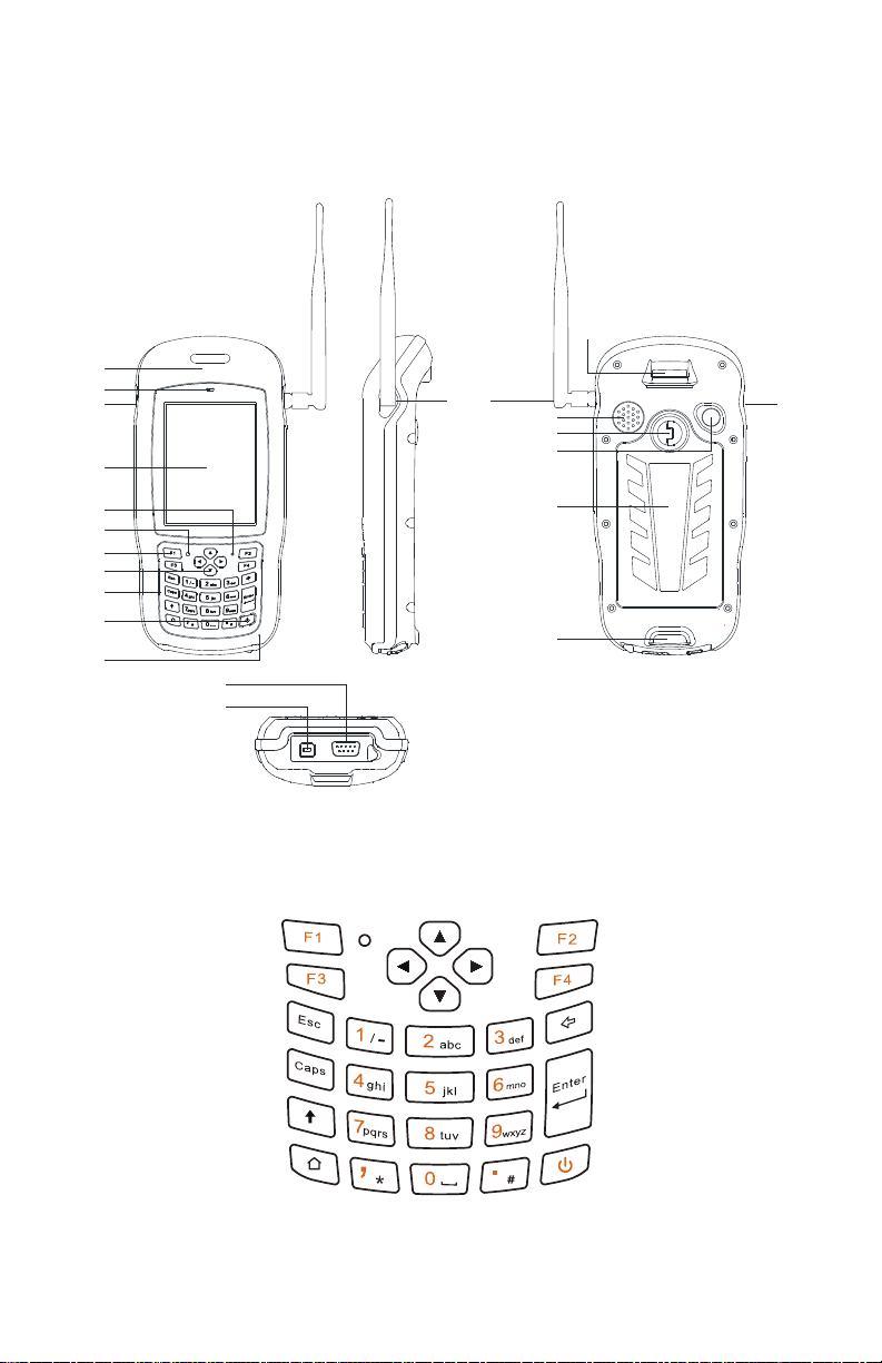
1. Appearance
1.1. General Diagram
Wristband
Hole
GNSS Antenna
Receiver
GNSS IN GNSS IN
LCM
Power/Charging
LED
Reset Key
Function Key
Direction Key
Keyboard
Power Key
MIC
COM 1 DB9
USB-B
Charging/Data Port
LRBT
Speaker
LOCK
Camera
Battery
Wristband
Hole
1.2. Keyboard
3
Page 5
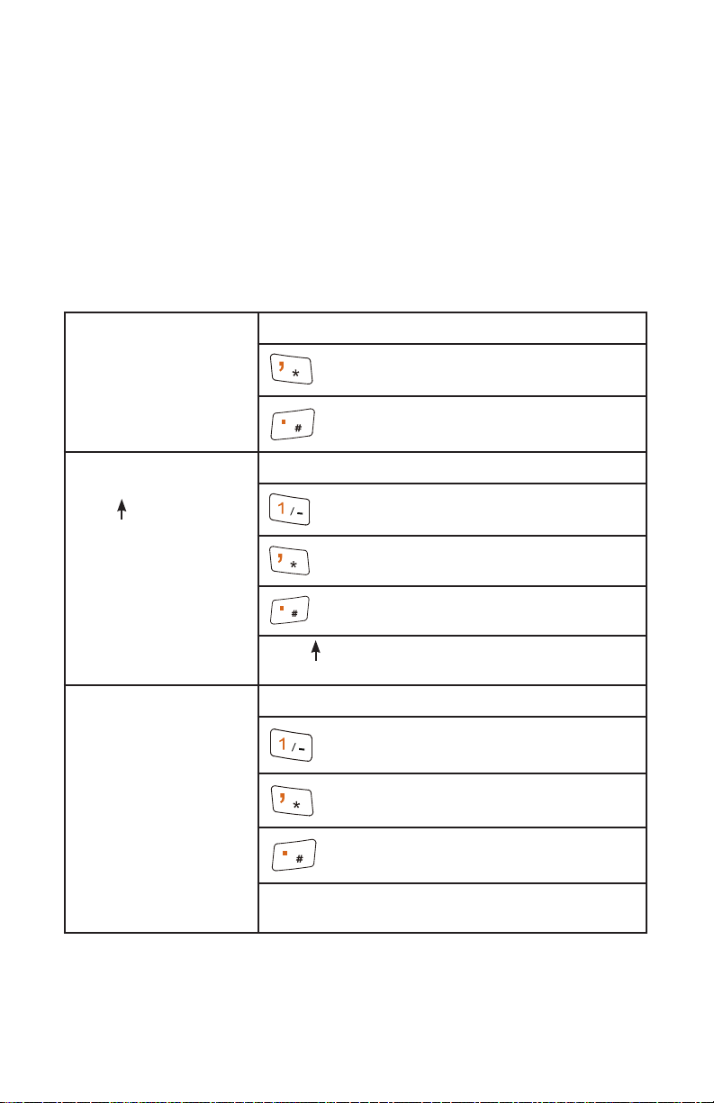
The yellow section is the system defaults, and the
functions of the 4 hotkeys are below:
F1: Start menu.
F2: Off.
F3: Camera.
F4: System main interface.
The other keyboard operation:
System defaults to the digital input method
System Default
,
.
Lowercase letters
Press (Shift)
Press Caps
Switch between / and -
*
#
Press (shift) again, it will be digital input
method
Capital letters
Switch between / and -
*
#
Press the Caps button again for lowercase
letters
4
Page 6
1.3. LED
Operation Power off Charging Full of
Using
charge
Light
Status
Off Red light
on
Off Green
light on
2. Operating Instructions
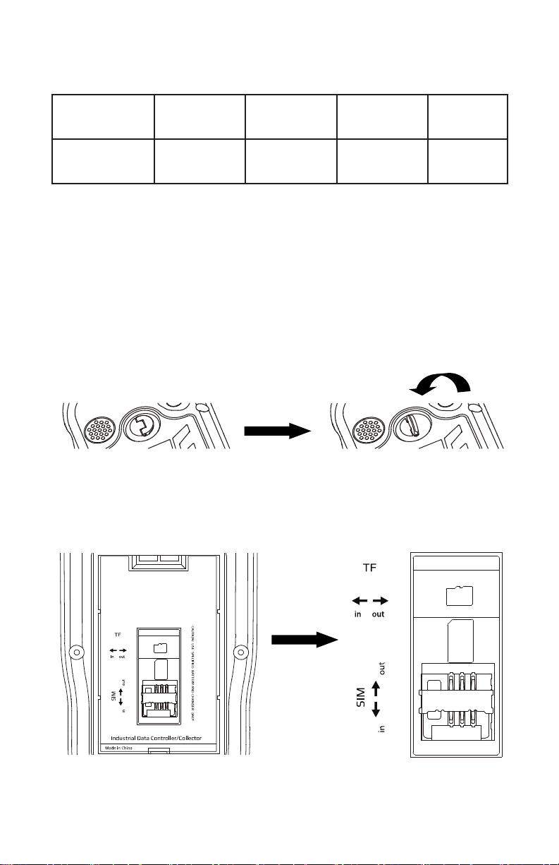
2.1. Installing the TF Card/SIM Card/Battery
a) Turn the back cover screw to the open position
according to the instructions on the back cover, and
take off the back cover.
b) Insert the SIM card and TF card according to the
instructions in the battery cabin.
5
Page 7
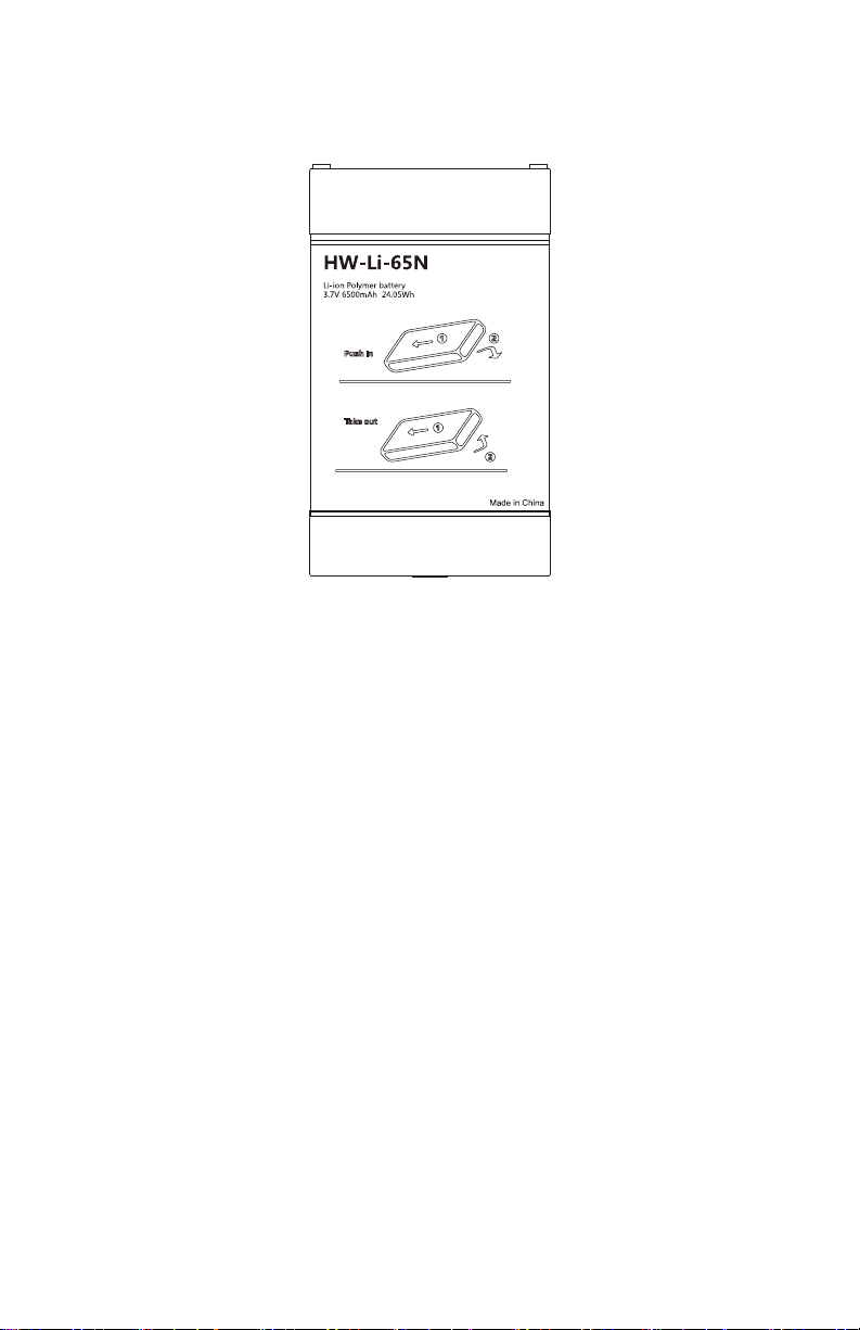
c) Insert the battery according to the instructions on the
battery label.
d) Close the back cover and turn the back cover screw
to the lock position.
2.2. Charging
a) The USB cable is used to charge the internal battery.
It will charge while the unit is connected to a
PC, or you can use the included wall adapter or
any 5 volt cigarette lighter USB charging port.
2.3. Turning the Collector On/Off
a) Make sure the battery has enough power, or connect
the HC3 to the AC adapter.
b) Press the power button for 3~5 seconds to turn on.
c) Press the power button for 3~5 seconds to power
off.
NOTE: Use the tip of the stylus to press the reset key to
restart the HC3 if necessary.
6
Page 8
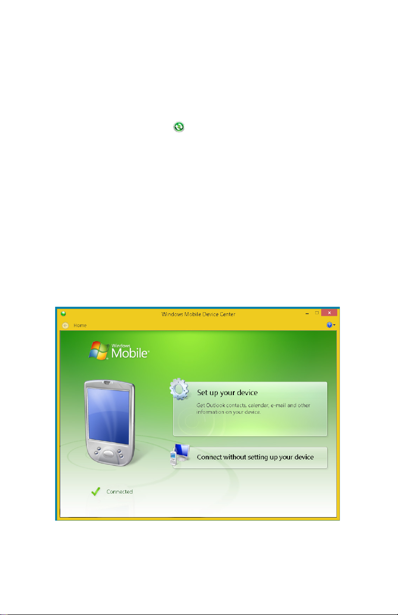
2.4. Connecting to a PC
a) Make sure WMDC (Windows Mobile Device Center)
has been installed in Vista/Win7/Win8/Win10 PC.
b) Connect the HC3 to a PC with the USB cable.
c) ActiveSync/WMDC will connect the HC3 and PC
automatically. The icon will appear in the tool
bar of the PC and also the ‘Synchronization
Setup Wizard’. Click ‘Cancel’ or
‘Connect without setting up your device’.
d) Click ‘Browse’ to check the files in the HC3 and then
transfer data between your PC and the HC3.
2.5. Installing SurvCE
a) Connect the HC3 to the USB port of a Windows
computer and wait for the Windows Mobile Device
Center to connect with the HC3.
7
Page 9
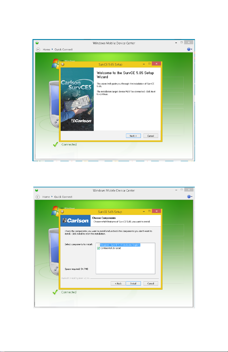
b) Locate and run the SurvCE_Install.exe file to install
SurvCE.
c) Select the Next button and accept the default
components to be installed.
8
Page 10
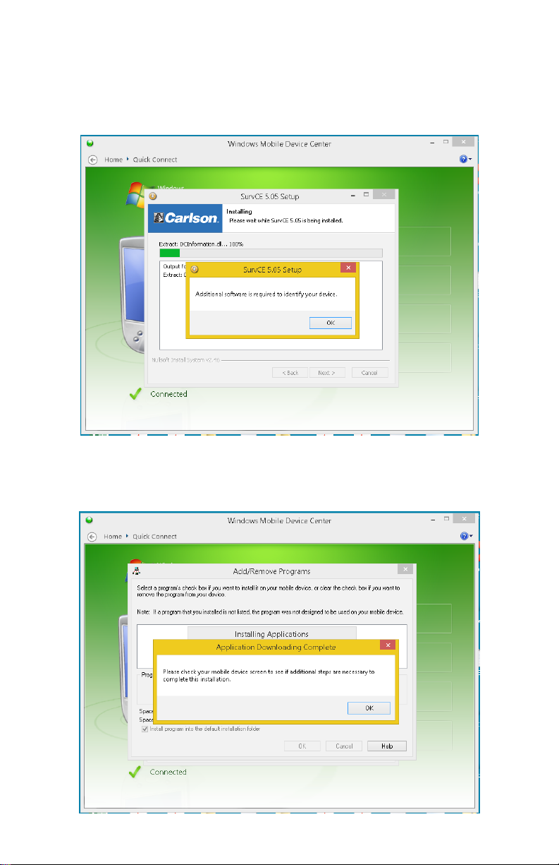
d) The installer will prompt you to install a program to
help it identify the HC3. Please OK this step and wait
for the program to complete its installation by
observing the screen on the HC3.
e) Once you click OK telling the installer that the above
software was installed, the SurvCE installation will
begin.
9
Page 11

f) When the installer finishes creating the install file,
you will see the install program begin on the HC3.
When it completes, there will be a SurvCE icon on
the home screen.
10
Page 12
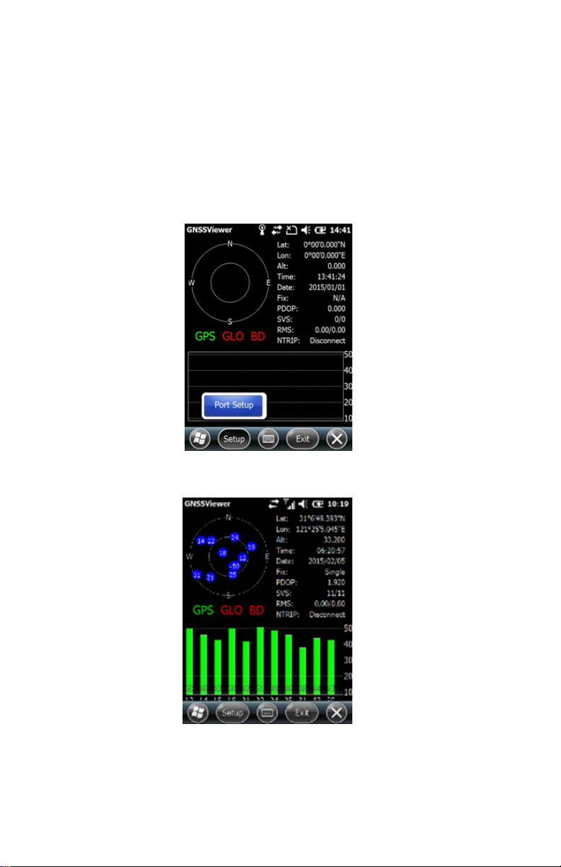
2.6. GNSS Status
a) Go to \My Device\GNSSViewer and run
GNSSViewer.exe.
b) The HC3 supports COM3 and GNSS ports and its
Baud Rate is 9600. Choose a GPS Port and Baud
Rate by clicking Setup -> Port Setup as indicated
below.
c) Click ‘OK’.
11
Page 13

2.7. Camera
a) Select ‘Start->Picture & Video’, select ‘Camera’ or
the camera icon to take photos.
b) Press the camera key (F3) to take photos.
c) Click screen and select ‘OK’ to exit.
2.8. 9 Pin Serial Port
The 9 Pin serial port is COM1. Transfer data between the
HC3 and other devices using the DB9 null modem serial
cable.
2.9. Wireless Connection (Bluetooth/GPRS/WiFi)
2.9.1. Standard Bluetooth
a) Select ‘Start->Settings->Connections->Wireless
Management’, click the icon to activate
the Bluetooth device.
b) Select ‘Start-> Settings-> Bluetooth’, click ‘Add new
device…’. Follow the tips shown on the screen
to finish the operation of pairing the other BT
Device.
2.9.2. Long Range Bluetooth (COM 2)
a) Select ‘Start’, click ‘BlueTooth Radio Manager’
b) Choose the mode of ‘DirectConn’, and press ‘Power
On’.
c) Select ‘Setup’ from the top of the screen and select
Baud Rate.
Continued on the next page
12
Page 14
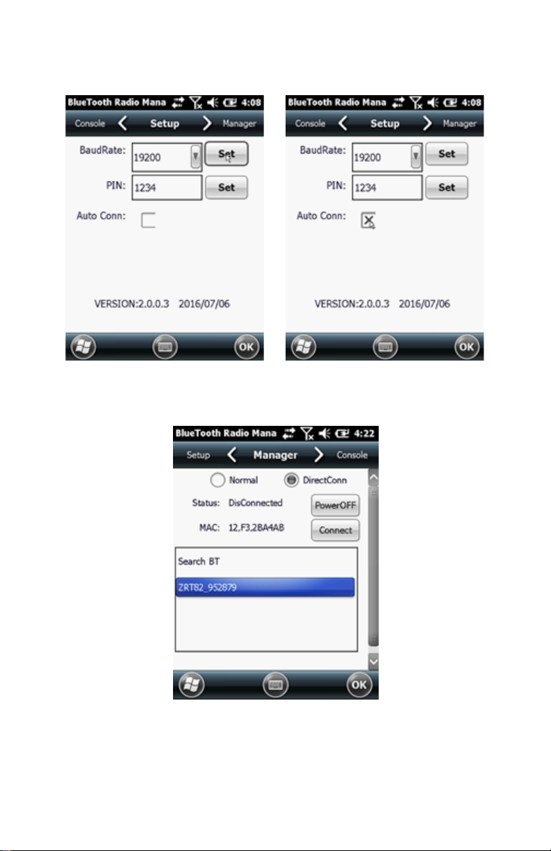
d) Select AutoConn to automatically reconnect on
startup.
e) Select ‘Manager’ from the top of the screen and
select ‘Search BT’.
f) After all BT devices have been found, select a device.
g) Click ‘Connect’ to pair with a BT device of your
choice. Your screen will display “Connect the
BT device successfully” after BT pairs successfully.
13
Page 15

2.9.3. WiFi
a) Select ‘Start->Settings->Connections->WiFi’.
b) Click ‘Search for Networks’, select a network listed.
Follow the installation guide to input a password and
confirm the connection to WiFi.
2.9.4. GPRS/3G Data Connection
a) Make sure there’s an activated SIM card in the HC3.
b) Select ‘Start->Settings->Connections->Connections’.
c) Click ‘Add a new modem connection’.
d) Input connection name “SimCard”, select ‘Cellular
Line (GPRS)’, click ‘Next’.
e) Input ‘Access point name’, click ‘Next’.
f) Click ‘Finish’ and add new connection successfully.
g) Click ‘Manage existing connections’.
h) Click and hold on “SimCard” and select ‘Connect’.
i) If there is the identifier on the signal icon in the top
right corner, this indicates a successful connection.
3. Useful Functions
3.1. Screen Response
Select ‘Start-> Settings-> System-> Screen‘,
click the ‘Align Screen‘ icon and follow the
guide to align the screen.
3.2. Adjusting the Backlight
Select ‘Start-> Settings-> System-> Backlight’
to adjust backlighting according to the guide.
Continued on the next page
14
Page 16

3.3. Removing Programs
Select ‘Start-> Settings-> System-> Remove
Programs‘. Select the programs you wish to
remove in the list and click ‘OK’ to remove.
3.4. Auto Power Off*
*NOTE: The device does not support the Auto Power Off
function, instead use Go-To-Sleep mode.
Select ‘Start-> Settings-> System-> Power->
Advanced’. Set the power off time in different
conditions. Backlight will be off according to
selected settings.
3.5. Clean Boot
*NOTE: The password is ‘1234’. Restoring factory settings
will clear the system configuration. Please be cautious.
Select ’Start-> Settings-> System-> Clean
Boot’ to restore factory default settings
according to the guide.
3.6. PWConfig
*NOTE: While on “Screen Off” mode, the device won’t
hibernate.
Select ‘Start-> Settings-> System-> pwconfig’.
15
Page 17

4. Accessories
4.1. Standard Accessories
Item Name Description Quantity
1 DC Adapter 110 V/DC 5 V/1 A 1
2 USB Cable USB to B-TYPE USB cable 1
3 Serial Cable DB9 null modem serial cable 1
4 Li-ion Battery 3.7 V/6500 mAh 1
5 Strap Black, 180*12 mm 1
6 Stylus Black, 127 mm 1
7 Screen
Protection Film
8 User Guide Paper version 1
9 Antenna Long range Bluetooth antenna 1
57*76 mm, 3 H & screen
microfiber cloth
2
4.2. Optional Accessories
Item Name Description Quantity
1 TF Card Memory capacity: 8G 1
2 Mounting
Bracket and
Pole (Claw)
Clamp
3 External
Champion
AS1-FS GNSS
Antenna
4 External
Antenna Cable
5 2 Meter GNSS
Poll
6 Bipod Bipod for GNSS 2 m poll 1
HW-02 1
GPS: L1 C/A, L2E, L2C, L5
GLONASS: L1 C/A, L1P, L2
C/A, L2P
BeiDou: B1, B2, B3
SBAS: L1 C/A and QZSS L1
Galileo: E1, E5a, E5b
Gain: 40dB, TNC Connector
3’ Fischer to TNC male cable 1
Fixed height 2 m poll for
external antenna
1
1
16
Page 18

5. Environmental Specifications
a) Operating temperature: -20 ºC ~ +60 ºC
b) Storage temperature: -30 ºC ~ +70 ºC
c) Drop: 1.2 M drop tested on all surfaces
d) Casing: Dustproof and resistant to heavy wind driven
rain per IP54 standard
e) Humidity: 5% ~ 95% (non-condensing)
6. Warranty Terms
The Champion HC3 series is guaranteed against defective
material and workmanship under normal use and
application consistent with this Guide. The equipment is
guaranteed for the period indicated on the warranty card
accompanying the product starting from the date that the
product was sold to the original purchaser by an Authorized
Champion Dealer.
During the warranty period, Champion will, at its option,
repair or replace this product at no additional charge.
Repair parts and replacement products will be furnished
on an exchange basis and will be either reconditioned or
new. This limited warranty does not include service to repair
damage to the product resulting from an accident, disaster,
misuses, abuse or modification of the product.
Warranty service may be obtained from an authorized
Champion warranty service dealer. If this product is
delivered by mail, purchaser agrees to insure the product
or assume the risk of loss or damage in transit, to prepay
shipping charges to the warranty service location and to
use the original shipping container or equivalent. A letter
should accompany the package furnishing a description of
the problem and/or defect.
The purchaser’s sole remedy shall be replacement as
17
Page 19

provided above. In no event shall Champion be liable for
any damages or other claim including any claim for lost
profits, lost savings or other incidental or consequential
damages arising out of the use of, or inability to use, the
product.
NOTE: Please use the original factory parts.
7. Contact Information
Champion Instruments
Suite 104
4317 Park Drive
Norcross, GA 30093
Telephone: (678) 386-2208
Web: www.ChampionInstruments.com
Email: Office@ChampionInstruments.com
8. Appendix – Product Safety Warnings
Safety and Compliance Information
• Use responsibly – Read all instructions and safety
information before use to avoid injury.
Battery Safety
• Charge battery only in temperature ranging from
32 ºF to 140 ºF (0 ºC to 50 ºC)
• CAUTION: Danger of explosion if battery is
incorrectly replaced. Replace only with the same or
equivalent type of battery recommended by the
manufacturer.
• The maximum operating ambient temperature of
the switching power supply declared by the
manufacturer is 50 ºC.
• Dispose of used batteries according to battery
manufacturer’s instructions.
18
Page 20

WiFi Safety
• Turn WiFi off in areas where WiFi use is prohibited
or when it may cause interference or danger, such as
in airplanes while flying.
Care and Maintenance
The HC3 is an electronic product and should be treated
with care. To reduce the risk of fire, electronic shock, or
product damage take the following advice:
• Do not expose this device to rain, moisture, or any
type of liquid that corrodes electronic circuits. If your
device gets wet, immediately turn the power off.
Allow the device to dry completely before using it
again.
• Clean the display with a soft cloth and be careful not
to wipe the display with anything abrasive.
• Do not expose your device to extreme heat (60 ºC )
or cold (-20 ºC ). For example, do not leave it
in the trunk of your car in high heat conditions.
• Do not attempt to open the device other than as
instructed in this manual.
• Rough handling can break the internal circuitry.
• Do not use harsh chemicals, cleaning solvents, or
strong detergents to clean the device.
• Use only the recommended accessories.
CAUTION!
CONNECTION TO A USB INTERFACE MUST BE LIMITED
TO USB VERSION 2.0 OR HIGHER
CONNECTION TO “POWER USE” MODE IS
PROHIBITED.
19
Page 21

9. Getting Started
9.1. HC3 RTK GNSS Bluetooth Base & Rover with
Carlson SurvCE
Step 1
The left images are the Base HC3 and the right images are
the Rover HC3. Either unit can be a base or rover. Once the
two units are powered on, pick the Windows icon on the
lower left of the screen, and the Start menu icons will
appear.
Step 2
Pick the BlueTooth Radio Manager icon to pair the units.
20
Page 22

Step 3
Set the Baud Rate and PIN as shown.
Step 4
From the Manager tab, search for the unit to bond with and
press the Connect button. You will see “Connect the BT
device successfully!” after each unit connects.
21
Page 23

Step 5
After creating a new job and selecting the coordinate
system and geoid separation file, select 2 GPS Base for the
base unit and 3 GPS Rover for the rover unit. Match the
settings below for each unit.
Step 6
22
Page 24

Step 7
The antenna shown in this configuration is the Champion
AS1-FS full spectrum external antenna on a 2 meter prism
pole.
Step 8
Note that all baud rates have been set to 115200. Selecting
the green check mark on the base continues through the
normal Base Configuration. On the rover, it completes the
setup process and progresses to “RTK L1 Fixed” as shown
on the Monitor/Skyplot screen.
23
Page 25

Step 9
Select the “Read From GPS” button to establish a known
base position.
Step 10
Average at least 10 positions.
24
Page 26

Step 11
Select “Yes” to complete the base setup. Expect a line of
site range of 3000’. Enjoy!
25
Page 27

9.2. HC3 RTK GNSS Network Rover with
Carlson SurvCE
Step 1
Connect the HC3 to the internet using either a GSM SIM
Card or a Wi-Fi hot spot. The picture below shows a WiFi
connection to the “eGPSGuest” network. Once you see the
name of the hotspot displayed on the screen, start Carlson
SurvCE and create a job with the correct coordinate system
and geoid separation file before configuring the rover. Next
select the Equip tab and then the GPS Rover button.
26
Page 28

Step 2
Under the Current tab, make the selections shown.
Step 3
Under the Comms tab, make the selections shown.
27
Page 29

Step 4
The antenna shown in this configuration is the Champion
AS1-FS full spectrum external antenna on a 2 meter prism
pole.
Step 5
Under the RTK tab, make the selections shown. These
selections assume that you have a network account with a
corrections provider that provides a mount point for the
u-blox-M8P-2 receiver. If one is not available, you may use
another HC3 as a base and connect to it using long range
Bluetooth or a GSM sim card with a static IP address.
28
Page 30

Step 6
Once corrections are being received under good
conditions, your HC3 will fix.
Only the following messages should be available through
the reference mount point.
1005 Stationary RTK reference station ARP
1074 GPS MSM4
1084 GLONASS MSM4
1124 BeiDou MSM4
1230 GLONASS code-phase biases
29
Page 31

Step 7
Step 8
Thank you for your HC3 purchase!
30
Page 32

9.3. HC3 RTK GNSS GSM Multi-Rover with
Carlson SurvCE
Step 1
The left images are the Base HC3 and the right images are
the Rover HC3. Either unit can be a base or rover.
Base:
The GSM network on the base must be started from
Windows at this time but will be automatic after 5.06. Pick
the Windows icon on the lower left corner of the screen to
get to the start menu.
Rover:
Start SurvCE.
31
Page 33

Step 2
Base:
Pick the Settings icon.
Rover:
Select the Equip tab and then the GPS Rover button as
shown.
Step 3
Base:
Pick the Connections folder icon.
Rover:
Configure as shown.
32
Page 34

Step 4
Base:
Pick the connections icon to open the connection manager.
Rover:
Configure as shown.
Step 5
Base:
Select Manage existing connections.
Rover:
Configure as shown.
33
Page 35

Step 6
Base:
Press and hold the SimCard modem connection previously
configured to start the network connection.
Rover:
Configure as shown.
Step 7
Base:
Start SurvCE and begin the base configuration as shown.
Rover:
Configure as shown using the IP address of YOUR Base, not
the one displayed.
34
Page 36

Step 8
Base:
Configure as shown.
Rover:
Configure as shown and press the green check mark.
Step 9
Base:
Configure as shown.
Rover:
Be patient.
35
Page 37

Step 10
Base:
Configure as shown.
Rover:
Enjoy!
Step 11
Base:
Configure as shown.
36
Page 38

Step 12
Base:
Configure as shown.
Step 13
Base:
Configure as shown.
37
Page 39

Step 14
Base:
Please select “Read From GPS” for the initial
configuration.
Step 15
Base:
Configure as shown.
38
Page 40

Step 16
Base:
Configure as shown.
Step 17
Base:
Select No for the initial configuration.
39
Page 41

Step 18
Base:
The TCP/IP Server screen will be displayed when the base
is ready to broadcast corrections. Note that the number of
rovers connected is 0 until 1 or more HC3’s connect.
Step 19
Base:
Snapshot of an actual incoming connection showing 1 rover
connected. The IP Address shown on YOUR screen is the IP
Address you used to configure YOUR HC3’s in step 7. You
are now ready to configure your HC3 rover(s).
40
Page 42

10. HC3 Specifications
Overview
Processor 1 GHz
Storage 1GB (expandable to 33GB using a
MicroSD card)
RAM 512MB
Operation System Windows Embedded 6.5
Multi-Language
Keypad 27 numeric + programmable keys
Mic
Speaker
Display 3.7” sunlight readable with
Display Resolution 480 x 640
Camera 5 megapixel
Dimension 7.87”(W) x 3.78”(H) x 1.26”(D)
Weight 1.2 lbs with battery
Communications and Data Storage
Long Range Bluetooth HC3 Base to HC3 Rover: 3000 ft;
GSM/3G 3G
WiFi
USB Port Type B USB
Serial Port DB9 (RS232)
Voice
Power
DC Input DC 5 V, 1 A
Detachable Li-ion Battery 6500 mA, 3.7 V
Environmental Specifications
Operating Temperature -20 °C ~ +60 °C (-4 °F ~ 140 °F)
Storage Temperature -30 °C ~ +70 °C (-22 °F ~ +158 °F)
Limited Dust and Water IP54
Drop 1.2 m protection
ü
ü
ü
integrated touchscreen
HC3 to Zoom90: 3050 ft
ü
ü
41
Page 43

Parameter Specification
Receiver
Type
Time-ToFirst-Fix
1
Sensitivity
72 channel u-blox M8 engine
GPS L1C/A, GLONASS L1OF, BeiDou B1I
GPS &
GLONASS
GPS &
BeiDou
Cold Start 26 s 28 s 29 s
Hot Start 1 s 1 s 1 s
2
Reacquisition -160 dBm -160 dBm -160 dBm
GPS
Cold Start -148 dBm -148 dBm -148 dBm
Hot Start -157 dBm -157 dBm -157 dBm
Convergence
3
Time
Horizontal
Position
RTK 2 min
4
Standalone52.5 m CEP
3, 6
RTK
0.025 m + 1 ppm CEP
2 min
4
3.5 min
Accuracy
Table 1: NEO-M8P performance in different GNSS modes (default:
concurrent reception of GPS and GLONASS)
__________________________________
4
1
All satellites at -130 dBm
2
Demonstrated with a good external LNA
3
Depends on atmospheric conditions, baseline length, GNSS antenna,
multipath conditions, satellite visibility and geometry
4
Measured with 1 km baseline, patch antennas with ground planes;
GPS+BeiDou measured in Singapore
5
Circular Error Probability (CEP), 50%, 24 hours static, -130 dBm,
> 6 SVs
6
ppm limited to baselines up to 10 km
42
Page 44

 Loading...