

Page 1
3227486 Rev. H 10/18
CA18-2-635 4th Edition
INSTRUCTION MANUAL
Contents
GENERAL SAFETY INFORMATION ...................................1
1.0 INSTALLATION ..........................................................2
2.0 OPERATION ..............................................................3
3.0 MAINTENANCE ........................................................4
TROUBLESHOOTING GUIDE .............................................6
SPECIFICATIONS ......................................................... 7-8
ELECTRICAL SCHEMATICS ...............................................9
DIMENSIONS AND WEIGHTS ................................... 10-12
PARTS LIST .............................................................. 13-14
WARRANTY ..................................................................16
GENERAL SAFETY INFORMATION
1. Pressurized devices
This equipment is a pressure containing device.
• Do not exceed maximum operating pressure as shown
on equipment serial number tag.
• Make certain equipment is depressurized before servicing.
2. Electrical
This equipment requires electricity to operate.
• Install equipment in compliance with national and local
electrical codes.
• Standard equipment is supplied with NEMA 1 electrical enclosures and is not intended for installation in
hazardous environments.
• Disconnect power supply to equipment before
servicing.
3. Breathing air
• Air treated by this equipment may not be suitable for
breathing without further purification. Refer to OSHA
standard 1910.134 for the requirements for breathing
quality air.
CRH SERIES
HIGH INLET
TEMPERATURE
REFRIGERATED
COMPRESSED
AIR DRYERS
Page 2
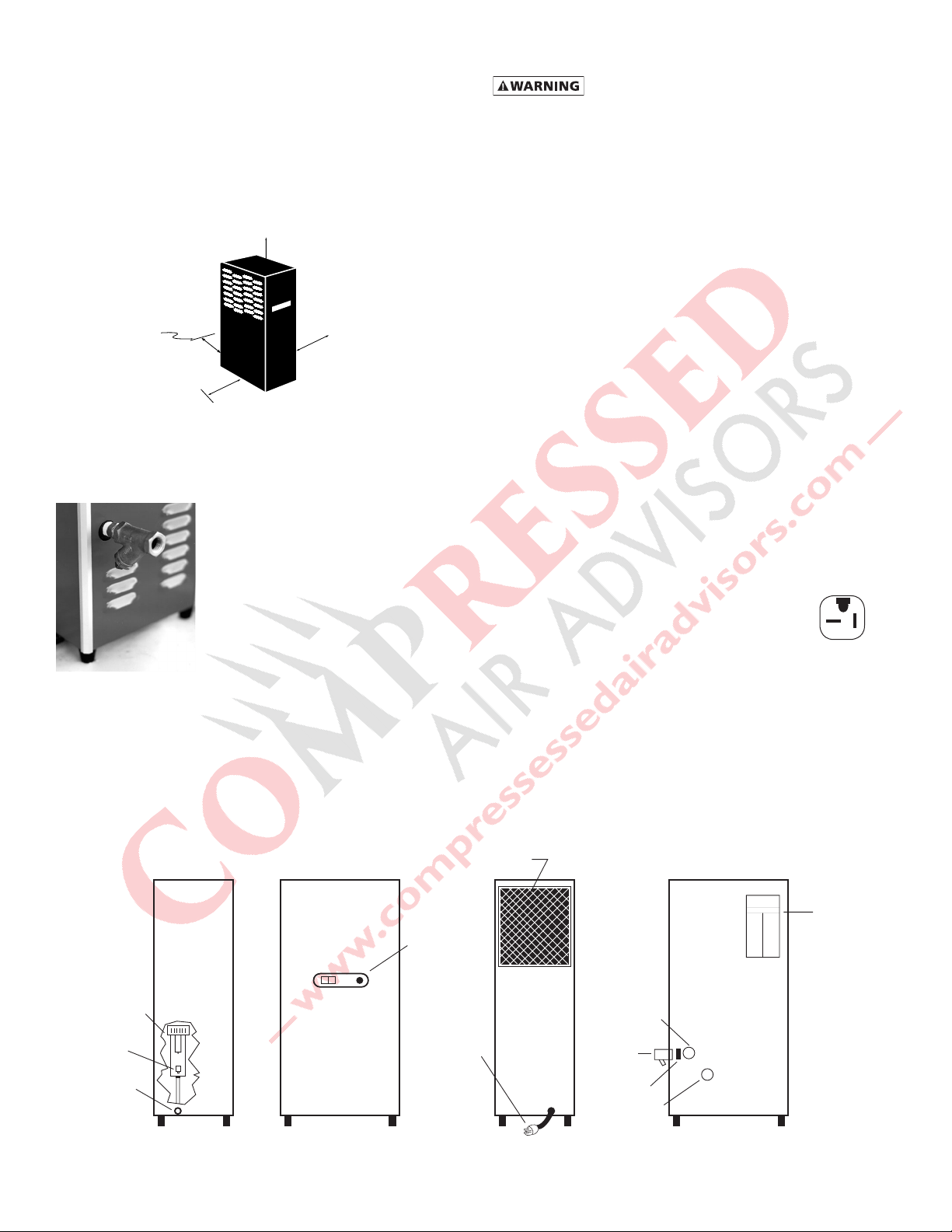
Ambient Air Filter
1.0 INSTALLATION
24"
12"
wall
6"
36"
1.1 Location
A. Air compressor intake - Locate air compressor so that
contaminants potentially harmful to the dryer are not
drawn into the air system.
B. Free air flow - Do not block either side of the cabinet.
Observe minimum installation clearances as shown.
1.2 Mounting
Dryer is suitable for floor or shelf mounting.
2. Location in the compressed air system
A. Maximum working pressure - 250 psig,
17.6 kgf/cm2. Do not exceed unit’s Maximum Working
Pressure.
1) For maximum capacity, install unit in air system at
highest pressure possible (e.g. before pressure reducing valves)
2) For maximum capacity, install unit at coolest compressed air temperature possible. Maximum inlet
compressed air temperature: 180°F, 82°C. If inlet air
exceeds this temperature, precool the air by extending the piping between the compressor and the
dryer.
B. Air Outlet - Connect air outlet to downstream air lines.
C. By-pass piping - If servicing the unit without interrupting
the air supply is desired, piping should include inlet and
outlet isolation valves and an air by-pass valve.
D. Condensate drain - It is advisable to connect drain outlet
to the condensate drainage system.
NOTE: Drain discharge is at system pressure. Drain line
should be anchored to prevent whipping.
1.3 Piping connections
A. Air Inlet - Connect compressed
air line from air compressor to air
inlet using strainer supplied.
1. Install strainer (included in
shipping carton) prior to
dryer inlet using pipe nipple
supplied or other piping as
required.
NOTE: Observe flow direction arrows on strainer.
NOTE: Install strainer where it is easily accessible for cleaning.
NOTE: Use vibration dampener, if vibration exists in air line at
inlet to dryer.
Control
Panel
IO
Separator and
Integral Filter
Drain
Mechanism
Drain
Connection
Electrical
Connection
1.4 Electrical connections
A. Dryer is designed to operate on power supply (voltage)
listed on serial number tag located on the back of the
dryer.
B. Dryer is supplied with an electrical cord. Install in recep-
tacle of proper voltage.
NOTE: Models 50 and 75 (115v only) - Install plug
in receptacle rated for 20 amps. Units are supplied
with 20 amp plug.
Plug
NOTE: Refrigeration system is designed to run continuously
and should NOT be wired to cycle on/off with the air compressor.
Serial Number
Tag
Air Inlet
Connection
Strainer
(shipped
separately)
Pipe Nipple
Air Outlet
Connection
Serial
Number
Tag
2
Left Side Front BackRight Side
Page 3
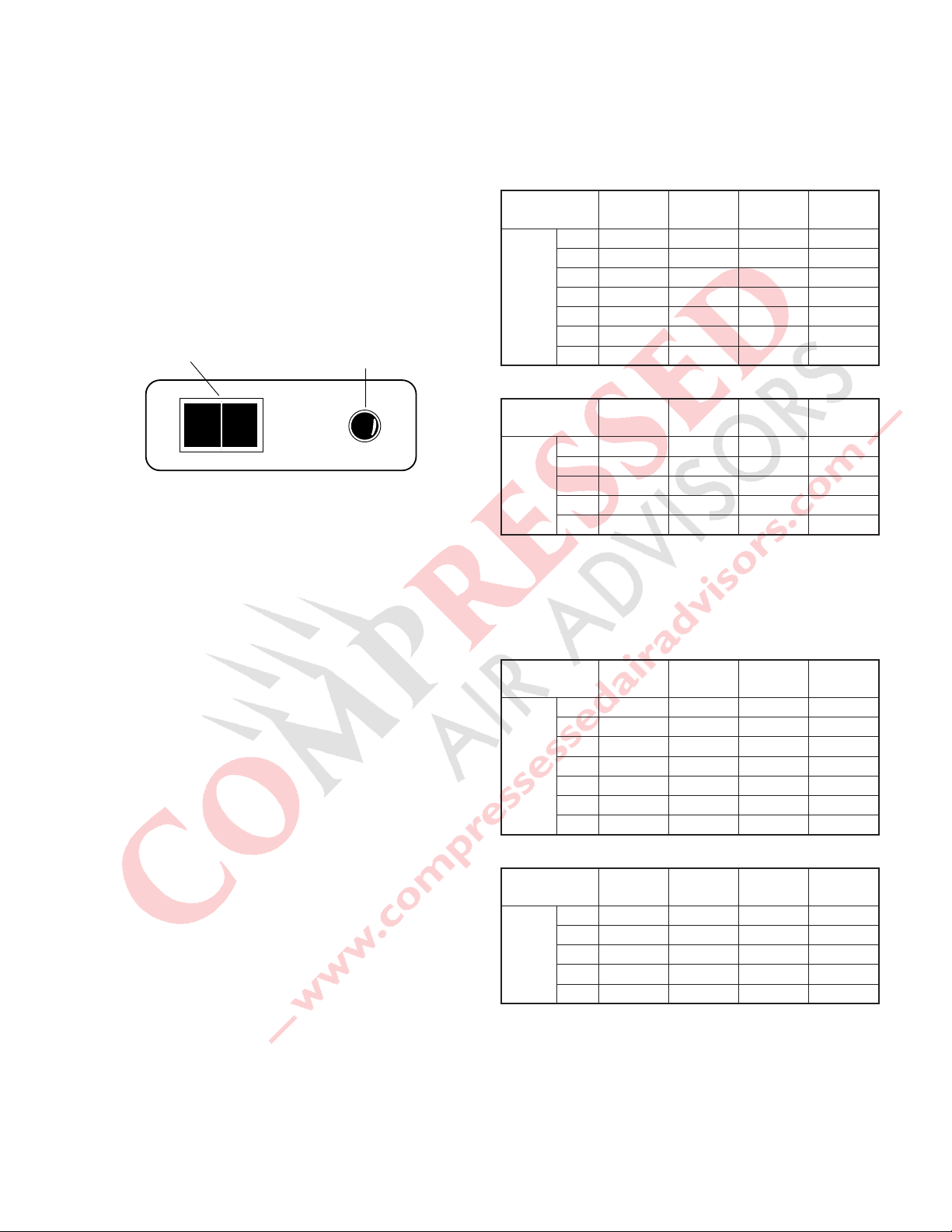
2.0 OPERATION
I
O
On/Off Switch
Fault Light
NOTE: Installations above 6000 feet, 1825 meters
Unit is adjusted to operate in altitudes up to 6000 feet, 1825
meters. If unit is installed in an altitude above this, and has
not been preset at the factory for this altitude, contact
Manufacturer’s Service Department.
2.1 Start-up
Start refrigeration system by pushing the on/off switch to
the ON position (depress rocker switch on side marked “I”).
NOTE: The fault light may illuminate when unit is energized.
Light should go out approximately 5 minutes after start-up.
If light remains lit after 30 minutes or illuminates after going
out, refer to Troubleshooting Guide.
Control Panel
2.2 Operating check points
Check the following on a periodic basis:
A. Rocker switch is in the ON position.
B. Amber fault light is out.
C. Condensate is being regularly discharged.
2.3 Minimum/maximum operating conditions
A. Minimum/Maximum air pressure: 20/250 psig,
1.4/17.6 kgf/cm
B. Maximum inlet air temperature: 180°F, 82°C
C. Minimum/Maximum ambient temperature:
40/110°F, 4/43°C
2
D. Maximum flow capacity
1. For dryers without an aftercooler installed upstream
Flow capacity in scfm (m3/min) @ 180°F, 82°C inlet
temperature, 160°F, 71°C inlet pressure dew point,
95°F, 35°C ambient temperature, and less than
5 psi, 0.35 kgf / cm2 pressure drop.
60 HZ
Inlet Pressure
psig (kgf/cm2)
Model
175 (12.3) 150 (10.6) 125 (8.8) 100 (7.0)
20 23 (0.65) 22 (0.62) 20 (0.57) 18 (0.51)
25 29 (0.82) 27 (0.76) 25 (0.71) 23 (0.65)
35 41 (1.16) 38 (1.08) 35 (0.99) 32 (0.91)
50 58 (1.64) 54 (1.53) 50 (1.42) 45 (1.27)
75 87 (2.46) 81 (2.29) 75 (2.12) 68 (1.93)
100 116 (3.29) 108 (3.06) 100 (2.83) 91 (2.58)
125 145 (4.12) 135 (3.82) 125 (3.54) 114 (3.23)
50 HZ
Inlet Pressure
psig (kgf/cm2)
Model
2. For dryers with an aftercooler installed upstream
Flow capacity in scfm (m3/min) @ 100°F, 38°C inlet
temperature, 100°F, 38°C inlet pressure dew point,
100°F, 38°C ambient temperature, and less than
10 psi, 0.7 kgf / cm2 pressure drop.
175 (12.3) 150 (10.6) 125 (8.8) 100 (7.0)
20 20 (0.57) 18 (0.51) 17 (0.48) 15 (0.42)
25 24 (0.68) 23 (0.65) 21 (0.59) 19 (0.54)
35 31 (0.88) 29 (0.82) 27 (0.76) 24 (0.68)
50 58 (1.64) 54 (1.53) 50 (1.42) 45 (1.27)
75 71 (2.01) 66 (1.87) 61 (1.73) 55 (1.56)
60 HZ
Inlet Pressure
psig (kgf/cm2)
Model
175 (12.3) 150 (10.6) 125 (8.8) 100 (7.0)
20 32 (0.91) 30 (0.85) 28 (0.79) 25 (0.71)
25 40 (1.13) 37 (1.05) 34 (0.96) 31 (0.88)
35 55 (1.56) 51 (1.44) 47 (1.33) 43 (1.22)
50 78 (2.21) 73 (2.07) 67 (1.90) 61 (1.73)
75 118 (3.34) 110 (3.12) 102 (2.89) 92 (2.61)
100 157 (4.45) 146 (4.14) 136 (3.85) 123 (3.48)
125 197 (5.58) 183 (5.18) 170 (4.82) 155 (4.39)
50 HZ
Inlet Pressure
psig (kgf/cm2)
Model
175 (12.3) 150 (10.6) 125 (8.8) 100 (7.0)
20 27 (0.76) 25 (0.71) 23 (0.65) 21 (0.59)
25 33 (0.93) 31 (0.88) 29 (0.82) 26 (0.74)
35 43 (1.22) 40 (1.13) 37 (1.05) 33 (0.93)
50 78 (2.21) 73 (2.07) 67 (1.90) 61 (1.73)
75 96 (2.72) 90 (2.55) 83 (2.35) 75 (2.12)
3
Page 4
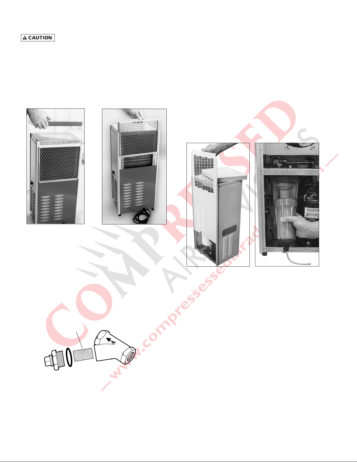
3.0 MAINTENANCE
Screen
DRYER IS A PRESSURE CONTAINING DEVICE.
DISCONNECT POWER AND DEPRESSURIZE DRYER BEFORE
SERVICING.
3.1 Ambient air filter - Clean accumulated dust and
dirt from ambient air filter monthly or more often
if air flow across the condenser is impeded.
A. Remove top panel.
B. Remove ambient air filter by sliding upwards.
3.3 Replace separator/filter element yearly or more
often if pressure drop across the dryer is excessive.
A. Shut-off compressed air supply to the dryer and depres-
surize. Turn off power to the dryer.
B. Remove top panel.
C. Remove two screws holding side panel and remove side
panel by sliding upwards.
D. Disconnect drain tube from bulkhead fitting in cabinet
base. To remove, press the plastic collar in, toward the
fitting, while pulling the tube out of the fitting.
E. Remove bowl - push bowl up, turn bowl 1/8th turn to
your left, and pull straight down.
F. Clean filter bowl.
G. Replace element.
C. Wash with soap and water and allow to dry before re-
installing.
NOTE: Do not use solvents to clean ambient air filter.
D. Reinstall filter and top panel.
3.2 Inlet strainer - clean inlet strainer monthly or
more often if rapid clogging occurs.
A. Shut-off compressed air supply to the strainer and de-
pressurize. Turn off power to the dryer.
B. Remove screen and clean or replace.
C. Reinstall.
1. Replacing complete element
a) Pull off old element and discard.
b) Make certain O-ring inside top of replacement ele-
ment is in place and push element onto filter head.
2. Replacing sleeve only
a) Pull element straight down to remove.
b) Remove bolt and bottom cap and remove disposable
filter sleeve.
c) Clean separator core with soap and water if necessary
d) Slide new filter sleeve over separator core and re-
place bottom cap and hand tighten bolt.
e) Make certain O-ring inside top of element is in place
and push element onto filter head.
4
Page 5
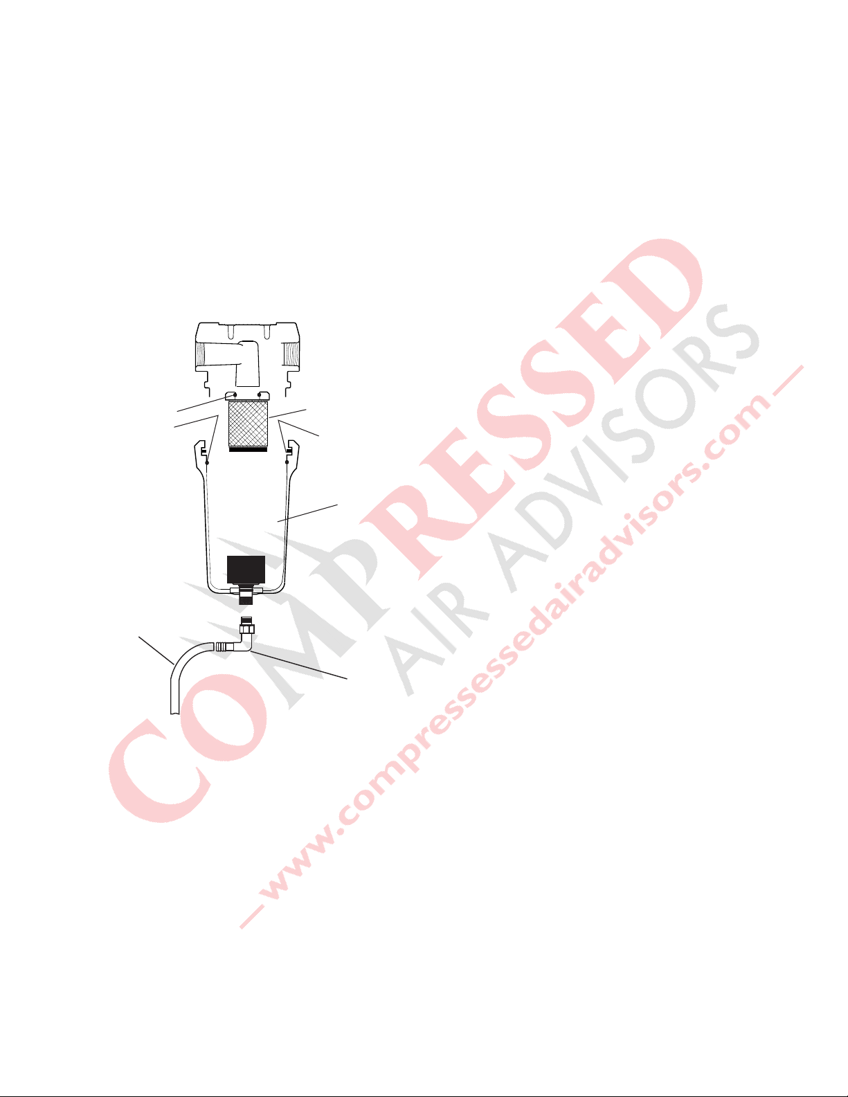
H. After making sure that O-ring and wave spring inside top
Element o-ring
Separator Element
Bowl o-ring
Drain Mechanism
Wave Spring
Tube
Hose
Barb
of bowl are in place, reassemble bowl to head.
NOTE: Make certain O-ring is generously lubricated
NOTE: Wave spring ends should be pointed down to prevent
the wave spring from interfering with reassembly.
I. Reconnect drain tube to bulkhead fitting by pushing
tube into fitting until it locks in position.
J. Reinstall side and top panels.
K. Restore power and repressurize dryer. Resume
operation.
3.4 Automatic condensate drain
• Check daily to be sure automatic drain is discharging.
• Replace drain mechanism yearly.
A. Shut-off compressed air supply to the dryer and depres-
surize. Turn off power to the dryer.
B. Remove top panel.
C. Remove two screws holding side panel then remove side
panel by sliding upwards.
D. Disconnect drain tube from bulkhead fitting in cabinet
base. To remove, press the plastic collar in, toward the
fitting, while pulling the tube out of the fitting.
E. Remove bowl - push bowl up, turn 1/8th turn to your
left, and pull bowl straight down.
F. Remove drain tube fitting from bottom of bowl.
G. Remove old drain mechanism by turning knurled fitting
to the right (clockwise) and remove.
H. Install new drain mechanism. If necessary, use a wire
or pencil to guide the new mechanism into place.
I. Reassemble drain tube fitting to bowl.
J. After making sure that large O-ring in filter head is in
place, reassemble bowl to head.
K. Reconnect drain tube to bulkhead fitting by pushing
tube into fitting until it locks in position.
L. Reinstall top and side panels.
M. Restore power and repressurize dryer. Resume
operation.
5
Page 6

TROUBLESHOOTING GUIDE
SYMPTOM POSSIBLE CAUSE(S) CORRECTIVE ACTION
A) Water downstream of dryer
B) High pressure drop across
dryer
1. Residual free moisture remaining in
downstream pipelines
2. Air by-pass system is open
3. Inlet and Outlet connections are
reversed
4. Temperatures surrounding air
lines downstream of dryer have
dropped below dryers dew point
rating.
5. Excessive free moisture (bulk liquid)
at dryer inlet
6. Condensate not being automatically drained
Drain mechanism is clogged or
inoperative.
Drain line is restricted or frozen.
7. Dryer overloaded resulting in elevated dew point.
8. Refrigeration system not functioning properly resulting in elevated
dew point.
1. Inlet air strainer clogged
2. Excessive air flow
3. Separator filter clogged.
4. Freezing of moisture in evaporator because of refrigeration
system improperly functioning.
Blow out system with dry air
Check valve positions
Check for correct connection
Insulate or heat trace air lines exposed
to low ambients or dry air to lower
dew point
Install separator ahead of dryer
Replace drain mechanism if inoperative
Open drain line
Check inlet air temperature and pressure, flow rate (compressor capacity)
and ambient air temperature
See D below
Clean inlet air strainer
Check flow rate
Replace filter sleeve
See D below
C) Fault Alarm
D) Refrigeration system not
functioning properly
1. When dryer on/off switch in on
or "I" position
2. Refrigerant compressor cycles on
and off
1. Dryer overloaded resulting in high
air outlet temperature.
2. Refrigeration system not functioning properly resulting in high
air outlet temperature.
3. Unit functioning normally but
thermostatic switch is malfunctioning or not securely mounted.
a. Power failure
b. Line disconnect switch open
c. Blown fuses, open breaker
d. Faulty wiring, loose terminals
a. High or low ambient conditions
b. Ambient air filter clogged
c. Condenser fins clogged
d. Fan motor or fan control
switch malfunction
e. Refrigerant leak
f. Low voltage
See A 7
See D below
Contact qualified refrigeration
repairman or manufacturer’s service
department
Check power to unit
Close disconnect switch
Check for continuity
Have electrician check electrical connections
Check minimum/maximum temperature ranges
Clean ambient air filter
Clean condenser
Replace fan motor or fan control
switch
Contact qualified refrigeration repairman or manufacturer's service
department
Check wiring
6
Page 7

SPECIFICATIONS - Models 20 through 75
Description
20 25 35 50 75
Model
Operating Conditions
Rated Capacity
@125 psig, 8.8 kgf/cm
scfm
2
*
m
3
/min
60 / 50 Hz
60 / 50 Hz
Maximum Working Pressure 250 psig (17.6 kgf/cm
20 / 17
0.57 / 0.48
25 / 21
0.71 / 0.59
35 / 27
0.99 / 0.76
2
)
50 / 50
1.42 / 1.42
Maximum Inlet Temperature 180°F (82°C)
Min/Max. Ambient Temperature 40-110°F (4-43°C)
Pressure Drop @
rated capacity
psi
(kgf/cm
2
)
60 / 50 Hz
60 / 50 Hz
4.5 / 2.9
(0.32 / 0.20)
3.3 / 2.4
(0.23 / 0.17)
4.7 / 2.9
(0.33 / 0.20)
4.5 / 4.5
(0.32 / 0.32)
Refrigeration System Data
Compressor Type Hermetic, Rotary, Permanent Split Capacitor
BTU/HR - Refrigeration Only
@ ASRE-T Conditions
60 / 50 Hz 8720 / 7043 12500 / 9970
Outlet Air Temperature
(nominal @ rated conditions)
155°F (68°C)
Refrigerant Type R-407C
Refrigerant Charge oz (grams)
60 / 50 Hz
Suction Pressure Setting 67 psig (4.7 kgf/cm
Factory Test (design) Pressure
high side/low side
Condenser Fan Switch Setting (in-out) 240-180 psig (16.9-12.7 kgf/cm
Air Flow Across Condenser cfm
3
m
/min
60 / 50 Hz
60 / 50 Hz
280 / 235
(7.9 / 6.7)
See Dryer Serial Tag
2
)
2
330/178 psig (23.2/12.5 kgf/cm
)
2
)
620 /515
(17.6 / 14.6)
Electrical Data
Unit
VAC/phase/Hz
115/1/60
115/1/60
Minimum/maximum volts 104 - 127
Full Load Amps (FLA) 8.7 12.6
Branch Circuit Fuse Size (amps) 15 20
Compressor
Volts/phase/Hz
115/1/60
Rated Load amps (RLA) 7.5 11.0
Locked Rotor amps (LRA) 44.0 67.0
Watts (input) 853 1220
Overload (External) Thermal and Current (Auto Reset)
Condenser fan motor
Volts/phase/Watts (output)
115/1/25 115/1/35
Full Load Amps (FLA) 1.2 1.6
Unit
VAC/phase/Hz
220-240/1/50
220-240/1/50
Minimum/maximum volts 198 - 264
Full Load Amps (FLA) 3.4 6.0
Branch Circuit Fuse Size (amps) 15
Compressor
Volts/phase/Hz
220-240/1/50
Rated Load amps (RLA) 2.8 5.1
Locked Rotor amps (LRA) 18.6 28.0
Watts (input) 690 990
Overload (External)) Thermal and Current (Auto Reset)
Condenser fan motor
Volts/phase/Watts (output)
220-240/1/18.3 220-240/1/25.6
Full Load Amps (FLA) 0.6 0.8
75 / 61
2.12 / 1.7
3.8 / 2.2
(0.27 / 0.15)
* Capacity @ 180°F, 82°C inlet temperature, 160°F, 71°C inlet pressure dew point, 95°F, 35°C ambient temperature, and less than
5 psi, 0.35 kgf / cm2 pressure drop.
7
Page 8

SPECIFICATIONS - Models 100 and 125
Description
100 125
Model
Operating Conditions
Rated Capacity
@125 psig, 8.8 kgf/cm
2
scfm
3
m
*
/min
60 Hz
60 Hz
Maximum Working Pressure 250 psig (17.6 kgf/cm
100
2.83
125
3.54
2
)
Maximum Inlet Temperature 180°F (82°C)
Min/Max. Ambient Temperature 40-110°F (4-43°C)
Pressure Drop @
rated capacity
psi
(kgf/cm
60 Hz
2
)
60 Hz
3.5
(0.25)
4.6
(0.32)
Refrigeration System Data
Compressor Type Hermetic, Scroll, Permanent Split Capacitor
BTU/HR - Refrigeration Only
@ ARI (60 Hz) Conditions
60 Hz 22500
Outlet Air Temperature
(nominal @ rated conditions)
155°F (68°C)
Refrigerant Type R-407C
Refrigerant Charge oz (grams)
60 Hz
Suction Pressure Setting 67 psig (4.7 kgf/cm
Factory Test (design) Pressure
high side/low side
Condenser Fan Switch Setting (in-out) 240-180 psig (16.9-12.7 kgf/cm
Air Flow Across Condenser cfm
m
3
/min
60 Hz
60 Hz
See Dryer Serial Tag
2
)
2
330/178 psig (23.2/12.5 kgf/cm
)
2
)
830
(23.5)
Electrical Data
Unit
VAC/phase/Hz
230/1/60
230/1/60
Minimum/maximum volts 207 - 253
Full Load Amps (FLA) 15.75
Branch Circuit Fuse Size (amps) 20
Compressor
Volts/phase/Hz
230/1/60
Rated Load amps (RLA) 14.9
Locked Rotor amps (LRA) 68.0
Watts (input) 2280
Overload (Internal) Thermal and Current (Auto Reset)
Condenser fan motor
Volts/phase/Watts (output)
230/1/60
Full Load Amps (FLA) 0.85
* Capacity @ 180°F, 82°C inlet temperature, 160°F, 71°C inlet pressure dew point, 95°F, 35°C
ambient temperature, and less than 5 psi, 0.35 kgf / cm2 pressure drop.
8
Page 9

ELECTRICAL SCHEMATICS
LINE
G
LINE
L2 L1
Models 20, 25, and 35
SW
2
1
G
4
2
3
3
3
3 1
14
OLT
HTS
FPS
WIRING SCHEMATIC
C S
5
M
LT
7
A
8
FM
RC
6
R
4
REFRIGERANT
COMPRESSOR
4
4
HIGH
TEMPERATURE
4
CONDENSER
FAN MOTOR
Models 50 and 75
LEGEND
Models 100 and 125
SW - On/Off Switch
OLT - Thermal Overload
3
SW
L2
L1
G
TB
3
3
4
4
FPS
8
LT
HTS
7
3
FM
4
A
4
C
3
5
4
4
10
S
2
PR
11
1
12R9
RC
SC
C
S
M
R
M - Compressor Motor
RC - Run Capacitor
HTS - High Temperature Switch
LT - Fault Light
FPS - Fan Pressure Switch
FM - Fan Motor
TB - Terminal Block
CT - Contactor w/115V Coil
SC - Start Capacitor
PR - Potential Relay
Models 20, 25, 35, 100, and 125
Front of Dryer
Right Side of Dryer
(Outside)
SW
LT
FPS
COMPONENT LOCATIONS COMPONENT LOCATIONS
(Inside)
FM
HTS
OLT
M
TB
SC, PR
(CRH 100/125 Only)
RC
Models 50 and 75
Front of Dryer
(Outside)
SW
LT
Right Side of Dryer
(Inside)
FM
HTS
OLT
M
RC
FPS
CT
9
Page 10

DIMENSIONS AND WEIGHTS
Models 20, 25, 35
Model Weight
20 79 lbs (36 kg)
25 80 lbs (36 kg)
35 81 lbs (37 kg)
28.1/4"
(718 mm)
1.9/16"
(40 mm)
12.1/2"
(317 mm)
DRAIN CONNECTION
CONEXION DEL DREN
VIDANGE AUTOMATIQUE
1" (25 mm)
4.1/8"
(105 mm)
1/4" NPT(F)
DRAIN CONNECTION
3/16"
(5 mm)
LEFT SIDE VIEW FRONT VIEW
5.1/16"
(128 mm)
10.1/8"
(257 mm)
8.9/16"
(217 mm)
FAULT
INDICATOR
INDICADOR
DE FALLA
INDICATEUR
DE BRIS
1/4"
(6 mm)
AIR FLOW
FAU LT
INDICATOR
LIGHT
ON/OFF SWITCH
13/16"
(21 mm)
(TYP)
POWER CORD
REPLACEABLE AMBIENT
AIR FILTER
12.7/8"
(327 mm)
11.5/16"
(287 mm)
4.1/8”
(105 mm)
1.1/2”
(38 mm)
AIR INLET
1/2" NPT(F)
8.1/2"
(216 mm)
1.11/16"
(41 mm)
5.1/8"
(130 mm)
BACK VIEWRIGHT SIDE VIEW
10.1/8"
(257 mm)
AIR OUTLET
1/2" NPT(F)
6.5/8"
(168 mm)
SERIAL
NUMBER
TAG
10
Page 11

DIMENSIONS AND WEIGHTS
Models 50 and 75
Model Weight
50 150 lbs (68 kg)
75 155 lbs (70 kg)
36.3/4"
(933 mm)
1.1/2"
(38 mm)
4.5/8"
(117 mm)
DRAIN CONNECTION
CONEXION DEL DREN
VIDANGE AUTOMATIQUE
1/4" NPT(F)
DRAIN CONNECTION
1"
(25 mm)
16.1/2"
(419 mm)
3/16"
(5 mm)
8.7/16"
(213 mm)
16.7/8"
(425 mm)
15.1/4" (TYP)
(387 mm)
FRONT VIEWLEFT SIDE VIEW
1/4"
(6 mm)
AIR FLOW
FAULT INDICATOR
LIGHT
ON/OFF SWITCH
13/16" (TYP)
(21 mm)
16.7/8"
(429 mm)
5'-20 AMP POWER CORD
REPLACEABLE AMBIENT
AIR FILTER
1.9/16"
(39 mm)
5.1/16"
(129 mm)
SERIAL NUMBER
TAG
AIR OUTLET
3/4" NPT(F)
AIR INLET
3/4" NPT(F)
9.1/8"
(232 mm)
6.5/16"
(160 mm)
2.15/16"
(59 mm)
6.7/8"
175 mm)
BACK VIEWRIGHT SIDE VIEW
11
Page 12

DIMENSIONS AND WEIGHTS
Models 100 and 125
Model Weight
100 191 lbs (86.6 kg)
125 192 lbs (87.1 kg)
45.3/4"
(1162 mm)
1.9/16"
(39 mm)
5.3/4"
(146 mm)
LEFT SIDE VIEW
DRAIN CONNECTION
CONEXION DEL DREN
VIDANGE AUTOMATIQUE
1/4" NPT (F)
DRAIN CONNECTION
1"
(26 mm)
17.5/16"
(440 mm)
1/8"
(4 mm)
8.7/16"
(214 mm)
15.1/4" ( T YP. )
(388 mm)
FRONT VIEW
16.7/8"
(429 mm)
FAULT
INDICATOR
INDICADOR
DE FALLA
DE BRIS
1/4"
(6 mm)
AIR FLOW
FAULT INDICATOR
LIGHT
ON/OFF SWITCH
13/16"
(21 mm)
REPLACEABLE AMBIENT
16.7/8"
(429 mm)
AIR FILTER
SERIAL NUMBER
AIR OUTLET
1" NPT (F)
AIR INLET
1" NPT (F)
10.7/8"
(276 mm)
8.1/8"
(206 mm)
5'-20 AMP POWER CORD
5.1/16"
(129 mm)
(38 mm)
1.1/2"
2.3/4"
(70 mm)
7.5/16"
(186 mm)
RIGHT SIDE VIEW BACK VIEW
12
Page 13

PARTS LIST
PARTS DESCRIPTION 20 25 35 50 75
Separator
*Separator/Filter Cartridge
Filter Sleeve C35BEL C35BEL C35BEL C60BEL C100BEL
*Drain Mechanism C3152270 C3152270 C3152270 C3152270 C3152270
Bowl C3240333 C3240333 C3240333 C3223457 C3241108
*O-ring Bowl C3154585 C3154585 C3154585 C3162913 C3162913
Inlet (Compressed Air) Strainer
Strainer, inlet
*Screen, Strainer C3230672 C3230672 C3230672 C3230673 C3230673
Electrical
Switch On/Off
Light, Fault (amber)
Light, Fault (amber)
Cord Set
Cord Set
Capacitor, Run
Capacitor, Run
Switch, fault light w/conn. C3240331 C3240331 C3240331 C3240597 C3240597
115/1/60
220-240/1/50
115/1/60
220-240/1/50
115/1/60
220-240/1/50
Condenser Fan
Fan Motor
Fan Motor
Fan Blade
Fan Blade
115/1/60
220-240/1/50
115/1/60
220-240/1/50
Refrigeration System
Compressor
Compressor
Condenser C3221323 C3221323 C3221323 C3221324 C3221324
Hot Gas By-Pass Valve C3232549 C3232549 C3232549 C3232526 C3232526
Filter/Dryer C3223809 C3223809 C3223809 C3223809 C3223809
Fan Pressure Switch C3230755 C3230755 C3230755 C3230756 C3230756
115/1/60
220-240/1/50
Cabinet
*Filter, Ambient Air
Grommet (light & switch, front panel) C3224016 C3224016 C3224016 C3224016 C3224016
Foot, mounting C3223838 C3223838 C3223838 C3223838 C3223838
* Maintenance kits for the above models are available "*" indicates items included in the kits.
C35BE C35BE C35BE C60BE C100BE
C4009634 C4009634 C4009634 C4009635 C4009635
C3230775 C3230775 C3230775 C3230775 C3230775
C3227423 C3227423 C3227423 C3227423 C3227423
C3227424 C3227424 C3227424 C3227424 C3227424
C3221571 C3221571 C3221571 C3221572 C3221572
C3221422 C3221422 C3221422 C3221422 C3221422
C3220878 C3220878 C3220878 C3220878 C3220878
C3220872 C3220872 C3220872 C3220878 C3220878
C3228001 C3228001 C3228001 C3227992 C3227992
C3228002 C3228002 C3228002 C3227986 C3227986
C3219394 C3219394 C3219394 C3219395 C3219395
C3219394 C3219394 C3219394 C3219399 C3219399
C3221265 C3221265 C3221265 C3221267 C3221267
C3221266 C3221266 C3221266 C3221268 C3221268
C3223805 C3223805 C3223805 C3223806 C3223806
Maintenance Kits
For Dryer Models Kit Number
20, 25, 35 CRHMK4
50 CRHMK6
75 CRHMK5
13
Page 14

PARTS LIST
PARTS DESCRIPTION 100 125
Separator
*Separator/Filter Cartridge
Filter Sleeve C100BEL C100BEL
*Drain Mechanism C3152270 C3152270
Bowl C3241108 C3241108
*O-ring Bowl C3162913 C3162913
Strainer, inlet C4009636 C4009636
*Screen, Strainer C3230662 C3230662
Electrical
Switch On/Off
Light, Fault 230v C3227424 C3227424
Cord Set C3221573 C3221573
Capacitor, Run
Capacitor, Start
Relay, Potential
Switch, Fault Light w/conn. C3240597 C3240597
230/1/60
230/1/60
230/1/60
Condenser Fan
Fan Motor C3227986 C3227986
Fan Blade C3219404 C3219404
Refrigeration System
Compressor
Condenser C3221325 C3221325
Hot Gas By-Pass Valve C3232526 C3232526
Filter/Dryer C3223814 C3223814
Fan Pressure Switch C3230756 C3230756
230/1/60
Cabinet
*Filter, Ambient Air
Grommet (light & switch, front panel) C3224016 C3224016
Foot, mounting C3223838 C3223838
* Maintenance kits for the above models are available "*" indicates
items included in the kits.
C100BE C100BE
C3230775 C3230775
C7439986 C7439986
C7439985 C7439985
C7439984 C7439984
C7426401 C7426401
C3223807 C3223807
Maintenance Kits
For Dryer Models Kit Number
100 CRHMK3
125 CRHMK3
14
Page 15

NOTES
15
Page 16

WARRANTY
The manufacturer warrants the product it manufactures, when properly installed, operated, applied, and maintained in accordance with
procedures and recommendations outlined in manufacturer’s instruction manuals, will be free from defects in material or workmanship
for a period as specified below, provided such defect is discovered and brought to the manufacturer’s attention within the aforesaid
warranty period.
The manufacturer will repair or replace any product or part determined to be defective by the manufacturer within the warranty period,
provided such defect occurred in normal service and not as a result of misuse, abuse, neglect or accident. Normal maintenance items
requiring routine replacement are not warranted. The warranty covers parts and labor for the warranty period unless otherwise specified.
Repair or replacement shall be made at the factory or the installation site, at the sole discretion of the manufacturer. Although not required
for warranty consideration, it is recommended that the manufacture be contacted prior to doing any warranty related service work. This
action will provide guidance and instruction on the repair often times authorization to perform the work. NOTE: The manufacture reserves
the right to repair, replace in the case of warranty approval or reject the warranty claim once submitted.
Unauthorized service and use of unauthorized or pirated parts voids the warranty and any resulting charges or subsequent claim will
not be paid. Products repaired or replaced under warranty shall be warranted for the unexpired portion of the warranty applying to the
original product.
The foregoing is the exclusive remedy of any buyer of the manufacturer’s product. The maximum damages liability of the manufacturer
is the original purchase price of the product or part.
THE FOREGOING WARRANTY IS EXCLUSIVE AND IN LIEU OF ALL OTHER WARRANTIES, WHETHER WRITTEN, ORAL, OR STATUTORY, AND IS EXPRESSLY
IN LIEU OF THE IMPLIED WARRANTY OF MERCHANTABILITY AND THE IMPLIED WARRANTY OF FITNESS FOR A PARTICULAR PURPOSE.
THE MANUFACTURER SHALL NOT BE LIABLE FOR LOSS OR DAMAGE BY REASON OF STRICT LIABILITY IN TORT OR ITS NEGLIGENCE IN WHATEVER
MANNER INCLUDING DESIGN, MANUFACTURE OR INSPECTION OF THE EQUIPMENT OR ITS FAILURE TO DISCOVER, REPORT, REPAIR, OR MODIFY
LATENT DEFECTS INHERENT THEREIN. THE MANUFACTURER, HIS REPRESENTATIVE OR DISTRIBUTOR SHALL NOT BE LIABLE FOR LOSS OF USE OF
THE PRODUCT OR OTHER INCIDENTAL OR CONSEQUENTIAL COSTS, EXPENSES, OR DAMAGES INCURRED BY THE BUYER, WHETHER ARISING FROM
BREACH OF WARRANTY, NEGLIGENCE OR STRICT LIABILITY IN TORT.
Please note that the manufacturer’s warranty for this product is intended to cover manufacturing defects and therefore does not cover
consumable components (desiccants, filter elements, soft goods, standard maintenance kit wear items, etc.) or components that require
periodic user adjustment (expansion valve, hot gas bypass valve or cooling water regulating valve) or calibration (dew point elements/
sensors, gauge calibration, etc.)
Warranty Period
Parts and labor for two (2) years from the date of shipment from the factory.
An extended warranty of up to 5 years from the date of purchase may be available for your dryer. Please contact your local distributor for
more details of the requirements for activation of warranty extension
.
AUTHORIZATION FROM THE SERVICE DEPARTMENT IS NECESSARY BEFORE MATERIAL IS
RETURNED TO THE FACTORY OR IN-WARRANTY REPAIRS ARE MADE.
For Service: (724) 746-1100
Or visit Sales and Service at www.championpneumatic.com
 Loading...