

Page 1
Parts and Operator’s Manual
Ci 40 - Ci 110
Read this manual prior to installation and operation of this machine.
Manual No.: 975203 Rev. H
Effective: July 2002
Model : _____________
Serial Number: _____________
Page 2

Page 3

Champion Compressors Ltd. Manual No. 975203 Rev H
CONTENTS
1.0 PARTS ORDERING PROCEDURE.....................................................1
2.0 RECOMMENDED SPARE PARTS LIST.............................................2
3.0 INTRODUCTION.................................................................................3
4.0 SAFETY..............................................................................................4
4.1 General Safety Notes................................................................4
5.0 GENERAL DESCRIPTION AND OPERATION....................................6
5.1 General Description of the Dominator Ci Series........................6
5.2 Principle of Operation ...............................................................7
5.3 Control System .........................................................................8
5.4 Operating Temperature .............................................................8
6.0 TECHNICAL DATA..............................................................................9
7.0 INSTALLATION AND PRE START CHECKS....................................10
7.1 Location..................................................................................10
7.2 Connection To Air System ......................................................10
7.3 Electrical Connection..............................................................11
7.3.1 Ci 40 - 75 (Stop / start control).......................................11
7.3.2 Ci 75 / 110 (Star-delta, CSU).........................................12
7.3.3 Motor Rotation Direction................................................12
7.4 Mechanical Checks.................................................................13
7.4.1 Airend Check.................................................................13
7.4.2 Oil Level Check .............................................................13
7.4.3 Vee Belt Check ..............................................................13
7.4.4 System Isolating Gate Valve Check...............................14
8.0 OPERATION.....................................................................................15
8.1 Start-Up Procedure.................................................................15
8.2 Function Of Controls...............................................................15
8.2.1 Stop / Start (Standard Ci 40 - 75):.................................15
8.2.2 Star-delta, CSU (Option Ci75, Standard Ci 110):...........16
8.3 Control Pressure Switch..........................................................17
8.4 Protection Devices..................................................................18
8.5 Thermo Bypass-Valve.............................................................18
9.0 OPTIONS..........................................................................................19
Page 4

Champion Compressors Ltd. Manual No. 975203 Rev H
9.1 Lead/Lag, Remote Monitoring & Control.................................19
9.1.1 Central Control Box Operation...................................... 20
9.2 Lead/Lag Control.................................................................... 22
9.2.1 Lead / Lag Control Box Operation.................................22
9.3 Lead / Lag Pressure Switches................................................ 23
9.4 Acoustic Hood (Ci 40/55)........................................................24
9.5 Clean Air Pack (Dryer)............................................................24
9.6 Dirty Environment Filter (Cyclopac)........................................ 24
9.7 No Neutral & Hour-meter (Ci 40/55/75)..................................24
9.8 Duplex....................................................................................24
9.9 Base-mount............................................................................25
9.10 Sump Heater and Thermal Fan..............................................25
9.11 Auto Restart Option................................................................25
9.12 Phase Failure Relay (Ci 75/110 only)..................................... 25
10.0 MAINTENANCE ................................................................................ 26
10.1 General .................................................................................. 26
10.2 Daily Operation.......................................................................26
10.3 Maintenance Schedule........................................................... 27
10.3.1 Initial Service - 250 hours............................................27
10.3.2 Every 1,500 Hours....................................................... 27
10.3.3 Every 3,000 Hours (Or Yearly)....................................27
11.0 GENERAL ASSEMBLY COMPONENTS - Ci 40 / 55........................ 30
12.0 GENERAL ASSEMBLY COMPONENTS- Ci 75................................ 34
13.0 GENERAL ASSEMBLY COMPONENTS- Ci 110.............................. 40
14.0 INTEGRATED SCREW COMPONENTS- Ci 40 / 55.........................44
15.0 INTEGRATED SCREW COMPONENTS- Ci 75 / 110....................... 46
16.0 ELECTRICAL STARTER ASSEMBLY - Ci75SD/110........................48
17.0 CLEAN AIR PACK ASSEMBLIES.....................................................52
18.0 CYCLOPAC AIR INTAKE ASSEMBLIES.......................................... 56
19.0 ACOUSTIC HOOD ASSEMBLY........................................................58
20.0 AUTODRAIN ASSEMBLY.................................................................60
21.0 CONTROL BOX DOOR ASSEMBLY................................................62
22.0 CENTRAL CONTROL BOX ASSEMBLY..........................................64
23.0 LEAD / LAG CONTROL BOX DOOR ASSEMBLY............................ 66
Page 5

Champion Compressors Ltd. Manual No. 975203 Rev H
24.0 LEAD / LAG CONTROL BOX ASSEMBLY........................................68
25.0 DUPLEX ASSEMBLIES ....................................................................70
26.0 TROUBLESHOOTING.......................................................................72
27.0 GENERAL ARRANGEMENT DRAWINGS........................................73
29.0 CHAMPION NETWORK....................................................................91
APPENDIX A DN - METRIC NOMINAL SIZES..........................................94
Page 6

Page 7

Champion Compressors Ltd. Manual No. 975203 Rev H
1
1.0 PARTS ORDERING PROCEDURE
When ordering parts always indicate the Serial No. and Model No. of the
compressor.
The parts should be ordered from the nearest Champion Branch or Champion
Distributor from whom the compressor was purchased (see 29.0 Champion
Network). If for any reason parts cannot be obtained in this manner, please
contact Champion Compressors Head Office directly.
When ordering parts, please be careful to check with your part number
selection for either assembly or kit. If you have any questions, please contact
your nearest Champion Branch.
Page 8

Champion Compressors Ltd. Manual No. 975203 Rev H
2
2.0 RECOMMENDED SPARE PARTS LIST
Description Repair Kit
No.
Qty.
2.1 Parts required per 1,500 hour (Type B)
Service
Standard Air Filter Element - Ci 40-55 278766 1
Standard Air Filter Element - Ci 75-110 278767 1
Oil Filter Element Cartridge - Ci 40-110 278877 1
Cyclonic Air Filter Element - Ci 40-110(Optional) 270092 1
Lubricant - Shell Corena CH46 (See Section 6) 831015
2.2 Parts required per 3,000 hour (Type C)
Service (As above plus:)
Separator Element - Ci 40-55 278773 1
Separator Element - Ci 75-110 278765 1
Microfilter Element - Ci 40-55 (If fitted) 211756 1
Microfilter Element - Ci 75-110 (If fitted) 211760 1
Vee Belts (Refer Section 9.0 / 10.0) 2
2.3 Machine Spares
Thermo Valve Repair Kit - 70ºC - Ci 40-110 278875 1
Thermo Valve Repair Kit - 80ºC - Ci 40-110 278876 1
Minimum Pressure Valve Repair Kit - Ci 40-110 278775 1
Inlet Controller - Ci 40-55 278905 1
Inlet Controller - Ci 75-110 278830 1
Airend Seal Kit - Ci 40-110 278763 1
Sight Glass Kit - Ci 40-110 278780 1
O-ring Kit - Ci 40-110 278874 1
Tensiometer 270965 1
2.4 Upgrade Kits
Cyclonic Air Filter Kit - Ci 40-55 159022
Cyclonic Air Filter Kit - Ci 75-110 159023
No Neutral, Hour Meter - Ci 40-55 159021
Clean Air Pack (CRD006) - Ci 40 159036
Clean Air Pack (CRD009) - Ci 55 159037
Clean Air Pack (CRD012) - Ci 75 159038
Clean Air Pack (CRD018) - Ci 110 159039
Acoustic Hood - Ci40-55 159017
Auto Drain Kit 159041
Spare parts Warranty: Type B Service items are warranted f or 1000 hours. ULTIMIZER is warranted for 4000 hours (or 1 year,
whichever occurs first). CHAMPION Vee belts are warranted for 6000 hours, if installed by a Champion approved technician. The parts
subjected to warranty must be returned (freight pre-paid), with proof of purchase to Champion Compress ors. In general, machine spare
parts are warranted for six months from the date of invoice and subject to Champion Compress ors Ltd. standard Warranty P ol i cy, and
Terms and Conditions of Sale of Goods.
Page 9

Champion Compressors Ltd. Manual No. 975203 Rev H
3
3.0 INTRODUCTION
The Dominator range of rotary screw compressors provides efficient
compressed air in a modular design, which allows for customisation and future
expansion of air requirements.
The standard Dominator range of air compressors has many features and
innovations.
Some of these advanced features are as follows:
• Advanced, modified profile screw element.
• Integrated machine componentry for less connections, eliminating oil leaks.
• Simplified intake controller.
• Integrated spin-on separator element for easy servicing and very low oil
carry-over.
• Integrated oil filter, air filter and over pressure protection.
• Minimum noise emission through innovative design.
• Simple machine control and adjustment.
• Easy access to service components.
• Compact modular design which allows for flexible installation and complete
package models, with air receiver and refrigerant dryer, all mounted on the
one unit.
• Integrated thermovalve optimised for ambient conditions.
This operator's manual is written to assist the end user in gaining maximum
use from their compressor unit. Please familiarise yourself with the contents
before placing the unit into service. Correct installation and on going
maintenance using the Champion Maintenance Program and Service Contract
will provide years of trouble-free service.
A copy of this manual should be given to the personnel responsible for
operating the machine within your organisation.
All requests for information, service and spare parts should be directed to
your nearest Champion Compressors’ Customer Support Division, or your
Authorised Champion Compressors’ Service Agent.
Page 10

Champion Compressors Ltd. Manual No. 975203 Rev H
4
4.0 SAFETY
4.1 General Safety Notes
Champion Compressors manufacture the Dominator Ci series so that they
can be operated safely. Persons operating the compressor are ultimately
responsible for their own safety. The following safety precautions are
suggested as a guide to reduce the risk of injuries throughout the life of your
compressor.
• Do not operate the compressor in an unsafe condition. Tag the
compressor with an appropriate Warning Tag and render it inoperative by
disconnecting the power at the source. This will prevent others from being
able to operate it until it is repaired.
• Correct hearing protection must be worn by person(s) working on or around
the compressor whilst the compressor is in operation.
• Before removing the oil filler cap ensure the compressor is not running and
is not pressurised. Shut down the compressor, isolate and bleed the
compressor air receiver before attempting to remove the oil filler cap. Vent
all internal pressure before opening any line, fitting, valve, drain plug,
connection or other component. If you are unsure how to do this contact
your nearest Champion Service Agent.
• Do not vary pressure switch setting from those listed in Section 8.3 without
prior approval from Champion Compressors’ Engineering Department.
Failure to comply to this may void your warranty.
• Do not tamper with or remove the integrated screw or air receiver safety
valves.
• Clean up spills of lubricant or other combustibles immediately. Keep
sparks and other ignition sources at a safe distance. Do not allow smoking
near the compressor.
• Keep electrical wiring and connections clean, free from dust, oil and tightly
clamped.
• Do not operate compressor or optional dryer with any protective guards or
panels removed. This includes the Ci 75 & 110 cabinet, fan & belt guards
or motor fan cowlings. Keep loose clothing and parts of the body away
from fans and other moving parts at all times.
Page 11

Champion Compressors Ltd. Manual No. 975203 Rev H
5
Avoid touching hot fluid, hot surfaces and points of air discharge. The
surfaces of the cooler, motor and airend can become very hot in high ambient
conditions.
• Do not directly breathe the air from this compressor.
• Do not direct compressed air at any part of a person’s body.
When making adjustments or repairs to exposed live parts of the system
maintain dry footing, stand on insulating surfaces and do not contact any
other portion of the compressor. Make adjustments with one hand only so as
to minimise the possibility of creating a current path through the heart. Do not
leave the compressor unattended with open electrical enclosures. If
necessary to do so, disconnect and lock out all power at the source.
All electrical service or installation work must be carried out by a
qualified / certified electrician.
Page 12

Champion Compressors Ltd. Manual No. 975203 Rev H
6
5.0 GENERAL DESCRIPTION AND OPERATION
5.1 General Description of the Dominator Ci Series
Your new Dominator rotary screw compressor will provide you with product
reliability and greatly reduced maintenance, if maintained and operated in
accordance with this manual.
The protection devices fitted to this compressor are provided to offer safety of
operation. The operator is solely responsible for personal safety at all times.
These devices should not be adjusted except by an authorised Champion
Compressors service agent.
The machines can be adjusted to operate at maximum capacity at pressures
of 780,1000 & 1300 kPa, but are supplied as standard at 780 kPa.
For pressure other than standard, check with Champion Compressors’
Support Division should you wish to vary the operating pressure of your
machine.
As standard, each compressor is mounted on an air receiver. The Ci 40 & 55
is mounted on one 150L air receiver, and the Ci 75 & 110 are mounted on
twin tank 220L air receivers.
Optionally, each model can be accompanied by a clean air package
consisting of a refrigerated dryer and microcoalescing filter. Each model is
also available in a version mounted on rubber feet, for applications where a
receiver already exists. The innovative modular design of the Ci series allows
for easy configuration changes, (See Section 9 for full option descriptions).
The Ci 40 - Ci 75 machines all employ three phase direct-on-line starting
(DOL) via a combination pressure switch / off-auto control / starter and motor
overload. These machines will start and stop automatically depending on
system pressure requirements, while the lever control on the pressure switch
is set to ‘Auto’ mode. The Ci 75 is also supplied with an hour meter indicating
hours of operation for service intervals.
Page 13

Champion Compressors Ltd. Manual No. 975203 Rev H
7
The Ci 110 uses a three phase star-delta starter panel mounted in the lid of
the compressor cabinet. This machine runs continuously, loading and
unloading as required to meet system pressure needs. An Off/Auto switch
mounted in the lid panel of the compressor is provided as a means of control.
An hour meter is provided indicating hours of operation for service intervals.
The Star-delta, Constant Speed Unload (CSU) option is available on the
Ci 75 by customer request.
Service access for your machine is excellent, with ample space provided to
allow for easy servicing of components. All the serviceable components on
the machine are located in convenient positions requiring minimum
disturbance to your compressor package. All models employ a vertical fan
mounted oil cooler, and on the Ci 75 and Ci 110, an air aftercooler is also
provided as standard.
5.2 Principle of Operation
The main functional components of a Dominator rotary screw air compressor
are the integrated rotary screw airend, the drive motor and cooler assemblies.
Unlike other rotary screw air compressors, the integrated rotary screw airend
performs the task of multiple system components. This has the advantage of
reducing the number of connections between components, and also reducing
system complexity.
The integrated screw rotors draw air through the air filter and intake controller.
Oil is injected into the compression space to provide cooling, sealing and
lubrication of the rotors and bearings as they turn, compressing the air. The
compressed air/oil mixture is discharged into the integrated separator vessel,
where most of the oil is removed from the air/oil mixture by mechanical
separation. The glass fibre spin-on separator element removes the remaining
oil.
The oil that is removed by the separator element is returned to the airend
sump via the purge line sight glass. The oil is collected in the separator
vessel and piped to the oil filter, where oil is cleaned before being cooled in
the oil cooler and re-injected into the airend.
After the separator element, the compressed air then flows through the
minimum pressure valve to the air receiver (via the air aftercooler on Ci 75 &
110). The moisture condensation is accumulated in the air receiver and
removed by means of the receiver drain valve or auto drain.
Page 14

Champion Compressors Ltd. Manual No. 975203 Rev H
8
The minimum pressure valve maintains pressure in the integrated screw
during start-up and during off-load operation to assist oil circulation. Backflow of compressed air from the air mains into the separator is prevented by a
non-return valve which is incorporated in the minimum pressure valve.
5.3 Control System
The purpose of the control system is to regulate the compressor air intake to
match the amount of air being used. The major components of the control
system are the intake controller, solenoid valve and pressure switch.
As the compressor starts (Stop / Start control only) or switches into DELTA (or
run) mode (Star-delta, CSU Only), the solenoid valve is energised, allowing
the air to enter the compressor. The system pressure rises.
The compressor pumps until the pre-set UN-LOAD pressure switch setting is
reached. The pressure switch then de-energises the solenoid valve, closing
the intake valve and allowing the integrated screw to reduce sump pressure.
On the stop/start models (standard on Ci 40, 55, 75) the compressor will
come to a stop. The load/unload models (standard Ci 110) will continue to
unload (producing no air) for a set time, governed by the setting of the run-on
timer, after which the compressor will enter standby mode, ready to
automatically start when air demand exists.
When mains pressure falls to the pre-set LOAD pressure switch setting, the
solenoid valve is energised, signalling for the inlet valve to open, thus allowing
the compressor to build up pressure to the pre-set level again. This cycle
continues as long as air demand is present.
5.4 Operating Temperature
This unit is designed to work from 0°C to temperatures in excess of 40°C.
Where site ambient temperatures will exceed 40°C (for example in a boiler
room), then it is better to duct the cooling air to the compressor. The oil
temperature is regulated by a thermo-bypass valve. For details on thermobypass valve operation refer to Section 8.5.
Page 15
Champion Compressors Ltd. Manual No. 975203 Rev H
9
6.0 TECHNICAL DATA
UNIT
Ci 40 Ci 55 Ci 75 Ci 110
Pressure BAR 7 10 13 7 10 13 7 10 13 7 10 13
cfm 19 16 14 28 21 18 42 34 29 60 50 42
l/s 9.0 7.6 6.6 13.2 9.9 8.5 19.8 16.0 13.7 28.3 23.6 19.8
FAD
(Capacity)
m
3
/min 0.54 0.45 0.40 0.79 0.59 0.51 1.19 0.96 0.82 1.70 1.41 1.19
Drive
System
BELTS 2XPZ 2XPZ 2XPZ 2XPZ
Cooling Air
Vol.
L/Sec 250 250 1000 1000
Heat
Rejection
kW 5.1 7.0 9.5 13.4
Oil Fill Litres 3.5 3.5 4.0 4.0
Av. Sound
Pressure
Level
(10 Bar)
dB(A)
@ 1m
71
72
74
75
Air Outlet
Discharge
Size
DN
BSP ‘F’
DN20
3/4”
DN20
3/4”
DN25
1”
DN25
1”
Motor kW 4.0 5.5 7.5 11.0
RPM 50Hz
2890 2930 2930 2955
RPM 60Hz
3440 3480 3450 3545
IP 55 55 55 55
FLC / 380/50
A
8.5 / 9.4 11.8 / 12.9 15.7 / 17.3 (9.9) 22.8 / 14.3
o/load 415/50
A
8.1 / 8.9 11.1 / 12.2 14.7 / 16.2 (9.3) 21.2 / 13.4
Setting † 440/60
A
8.8 / 9.7 11.8 / 12.9 15.4 / 16.0 (9.7) 22.3 / 14.1
Australia:
Cable Size *
mm²
1.0 1.5 1.5 2.5
Fuse Size ♦
(MOTOR START)
A
25 32 35 35
Oils:
Factory Fill (Mineral)
SMARTLUBE CH46 SMARTLUBE CH46 SMARTLUBE CH46 SMARTLUBE CH46
High Ambient (Mineral)
SHELL CORENA S68 SHELL CORENA S68 SHELL CORENA S68 SHELL CORENA S68
Synthetic ♣
SULLUBE 32
SULLUBE 32 SULLUBE 32 SULLUBE 32
Motor Bearings SEALED BEARINGS - NO SERVICE REQUIRED
* Example as per AS3008.1.1 Selection of cables Table 12 (Column 4). Note that no
de-rating factors have been applied. Refer to AS3008.1.1 for correct selection and
installation.
♦ If circuit breakers are to be used, use only circuit breakers equivalent to MOTOR
START FUSE.
♣ Refer Champion Service if a change from mineral based oil to
synthetic is required.
† Overload settings in brackets are for Ci-75 with Star-delta starter.
Page 16

Champion Compressors Ltd. Manual No. 975203 Rev H
10
7.0 INSTALLATION AND PRE START CHECKS
WARNING: Incorrect Installation May Void War ranty.
Before installing your Champion Compressor check carefully for any transport
damage. Contact Champion Compressors immediately if any such damage is
found.
7.1 Location
The compressor cabinet as supplied is not weather-proof, and the compressor
should be installed inside (or in a sheltered location outside). The compressor
should be installed in such a way that the locations with respect to walls and
ceiling meet the requirements of the model general assembly diagrams.
(Refer Section 27).
The compressor must be placed on a flat surface and it must remain level at
all times. Packing shims should be used to level the compressor. The unit
must not be securely bolted down. When the need exists location pins should
be used.
IMPORTANT: Locate the compressor in an adequately ventilated area. Hot
air from the discharge duct must not recirculate to the air intake. Do not install
in an area where exhaust fumes from other equipment can be drawn into the
intake (or other toxic, noxious or corrosive fumes, chemicals or substances).
Where more than one compressor is installed in one location, not only must
proper care be taken with regard to access to each individual machine, but
special attention should be taken to ensure that there is no possibility of the
heated cooling air discharge from any one machine being directed into the
intake of another machine.
7.2 Connection To Air System
The compressor is supplied with either a 3/4” Gate valve (Ci 40/55) or 1” Gate
Valve (Ci 75/110) loose for installation into to ends of the compressor’s air
receiver. The connecting plant airline connection should be at least the size
of the prescribed gate valve, and if the pipe run is of any great length, the pipe
sizes should be increased by one size to minimise any pressure drop.
Note
: In base mount option configuration, the pressure switch is
supplied loose (on a 2m fly lead). This must
be fitted into the air supply
to provide a control signal for correct compressor operation.
Page 17

Champion Compressors Ltd. Manual No. 975203 Rev H
11
7.3 Electrical Connection
The electrical installation must be checked by a licensed electrician to ensure
that it is adequate for starting and running the compressor. Refer to Section 6
- ‘Technical Data’.
NEUTRAL CONNECTION IS REQUIRED ON SOME MODELS.
Champion Compressors has provided a circuit diagram at the rear of this
operator’s manual
.
7.3.1 Ci 40 - 75 (Stop / start control)
All the mains supply leads connect to the compressor within the cover of the
combination pressure switch and starter. There is connection for 3 phases,
earth and neutral. Note: The neutral connection is made on the shunt
relay contact block (located inside pressure switch cover), at terminal
‘C1’ marked on the relay. Please refer to circuit diagram supplied with your
machine.
Note:- A No-Neutral option is available for your compressor. Please contact
Champion Compressor’s customer support department for assistance.
Fig. 1 - Electrical Connection Ci 75 (Stop / Start Control)
Page 18
Champion Compressors Ltd. Manual No. 975203 Rev H
12
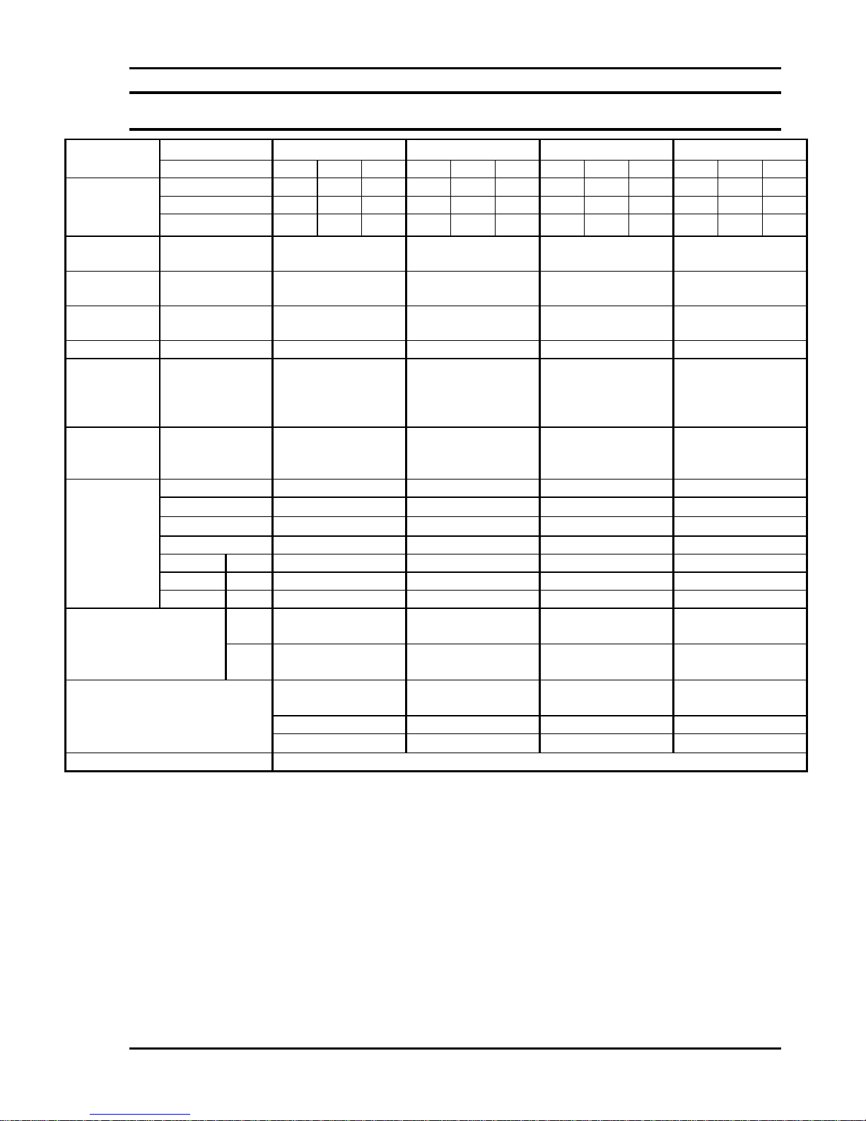
7.3.2 Ci 75 / 110 (Star-delta, CSU)
The main supply leads connect to the compressor through conduit entry
points on both the cabinet panels and electrical enclosure. The three phase
wires connect directly to terminals marked. Connection of the earth wire
should be bolted to the starter enclosure using the M6 earthing bolt provided.
Please refer to the circuit diagram supplied with your machine.
Fig. 2 - Electrical Connection - Ci75SD - 110
7.3.3 Motor Rotation Direction
The power supply must be correctly connected for the motor to rotate in the
correct direction. This can be checked by toggling the Off/Auto switch located
on the pressure switch / starter (Stop / Start) or the compressor lid (StarDelta, CSU). Note that if your machine is fitted with an auto restart facility,
there may be a delay of up to 30 seconds after toggling the Off/Auto switch.
The motor and airend rotate in the direction indicated by the arrow marked ‘D’
on the airend and motor fan cowling (anti-clockwise viewed from drive shaft
end). In the event that the motor has been disconnected or removed for
service reasons, ensure that the power supply is reconnected in the correct
sequence prior to start-up.
Change incoming power leads only. Refer to Work instruction Q36-34a
for correct wiring sequence.
WARNING: Rotation in the wrong direction will damage the airend and
will void warranty.
Page 19

Champion Compressors Ltd. Manual No. 975203 Rev H
13
7.4 Mechanical Checks
WARNING: Ensure that the machine is electricall y isolated before
checks are made.
7.4.1 Airend Check
Ensure that the airend is not hydro-locked by rotating the driven pulley by
hand through two complete revolutions.
7.4.2 Oil Level Check
Sight glasses are used to check both dynamic and static oil levels on these
models. The upper sight glass is used to check the static oil level, whilst the
lower sight glass is used to check the dynamic level.
Top-ups: Add prescribed grade of oil. Ensure that the oil filler cap is firmly
secured and seated properly on the seal, do not over tension.
7.4.3 Vee Belt Check
Pulley alignment must be checked by using a straight edge to confirm that the
pulley faces are flush, and drive shafts parallel. The maximum misalignment
allowable is 0.5mm.
Check that all belts are seated in their grooves. The belt tension is
maintained by sliding the motor, via adjusting jacking bolts located at the feet
of the motor. Correct belt tension is achieved with the use of a Tensiometer
(Champion Part No. 270965). Refer to Figure 3. Set the large o-ring so that
the o-ring bottom is at the 7mm mark. Ensure that the small o-ring is set at
the zero mark. Hold the top of the Tensiometer and press it at right angles to
the belts, midway between the airend pulley and motor pulley into one of the
v-belts. When the bottom of the large o-ring is level with the top of the other
belts stop pressing it in and read the kilogram figure off the bottom of the
small o-ring. Move the small o-ring back to the zero mark and repeat the
operation for the other belts. Record the results.
Rotate the motor pulley through one complete revolution and measure the
belts again, recording the results. Once again rotate the motor pulley and
take another set of readings. Average three sets of readings to ascertain a
belt tension figure.
Page 20

Champion Compressors Ltd. Manual No. 975203 Rev H
14
The belt tension must be adjusted between the minimum, maximum and initial
values (1.3 x Maximum) listed in the table below:
Model Minimum Maximum Initial
Ci 40 1.3 kg 1.8 kg 2.3 kg
Ci 55 1.4 kg 2.0 kg 2.6 kg
Ci 75 1.5 kg 2.1 kg 2.7 kg
Ci 110 1.9 kg 2.7 kg 3.6 kg
New belts should be initially tensioned to 1.3 times the maximum running
tension settings outlined above. Belt tension needs to be adjusted five
minutes after these belts are fitted and the compressor is run, then again ten
minutes later. This will ensure that the belts have completed their initial
“stretch”. After this first fifteen minutes of operation, the belts should be
correctly tensioned to the table above.
Fig. 3 - Belt Tensiometer Part Number 270965
7.4.4 System Isolating Gate Valve Check
Check that the isolating gate valve fitted to the compressor is open.
Page 21

Champion Compressors Ltd. Manual No. 975203 Rev H
15
8.0 OPERATION
8.1 Start-Up Procedure
If the compressor has not been started for a period of two months or longer,
carry out all the pre-start checks outlined in Section 7 prior to starting
machine.
1. Drain moisture from the compressors’ air receiver.
2. Drain any water that has condensed in the oil sump, (See Section 10.2)
3. Check that the proper oil level is visible in the upper oil sight glass.
Top up if necessary. Warning : Allow five minutes for oil level to settle
before opening the filler plug.
4. Ensure the isolating valve is opened.
5. Turn the ‘Off-Auto’ switch to auto (located on the lid on Star-delta
models) or adjust the lever to the ‘Auto’ position indicated on the
pressure switch (Stop/Start models).
Warning : Do not restart the unit within 30 seconds of shutdown. This allows
the separator vessel to fully vent, and prevents starting against load.
Should the machine show any excessive vibration, shut down and
contact the Champion Customer Support Division immediately.
To shut the compressor down, turn the ‘Off-Auto’ switch to the Off position
(Star-delta models) or move the lever on the pressure switch to the OFF
position (Stop/Start Models).
8.2 Function Of Controls
8.2.1 Stop / Start (Standard Ci 40 - 75):
The On / Off control, and system pressure gauge for the Ci 40 - 75 machines
is located on the pressure switch / starter assembly. While the switch is in the
‘Auto’ position, the machine will start and stop according to system pressure.
For directions on setting the pressure switch cut-in and cut-out pressures,
refer to section 8.3.
Page 22

Champion Compressors Ltd. Manual No. 975203 Rev H
16
8.2.2 Star-delta, CSU (Option Ci75, Standard Ci 110):
The ‘Off-Auto’ switch, emergency stop button and hour meter are located on
the lid of the machine. Unlike the Ci40 and 55 Dominators, the Ci 110 has
constant speed unloading as standard. The compressor runs off load rather
than stopping when the upper pressure setting has been reached. There is a
run on timer fitted to ensure that during periods of low air usage, the
compressor does not run unnecessarily. The factory setting of this timer is six
minutes, but it may be adjusted with specific installation requirements. Please
refer to Champion Compressors prior to any adjustments being made, as an
incorrect setting may result in damage to the compressor.
The compressor may start at any time whilst the compressor is in ‘Auto’ mode.
Please note that if your machine is fitted with Auto Restart option, there may
be a starting delay of up to 30 seconds after powering up the compressor. If
the emergency stop button is used to stop the compressor or to cut power to
the compressor, the Auto/Off switch must be toggled to restart the
compressor.
Warning : Do not remove covers or attempt any service without first ensuring
the compressor is isolated from the mains power supply, as the compressor
could start at any time.
Page 23

Champion Compressors Ltd. Manual No. 975203 Rev H
17
8.3 Control Pressure Switch
The control pressure switch (tank mounted or supplied loose on base mounts
for line mounting) has been set prior to leaving the factory with the following
settings:
Nominal
Operating
Pressure
(kPa)
Nominal
Pressure
Differential
(kPa)
Load
Pressure
(kPa)
Unload
Pressure
(kPa)
780 120 660 780
1000 120 880 1000
1300 120 1180 1300
If the settings have “drifted” during transport, it will be necessary to adjust
them on site. This is accomplished as follows (refer Figure 4):
1. Remove the protective cover from the pressure switch assembly.
2. (a) To increase pressure - turn range screw clockwise
(b) To reduce pressure - turn range screw anticlockwise
3. (a) To increase differential - turn differential screw clockwise
(b) To reduce differential - turn differential screw anticlockwise
For safety reasons, under no circumstances adjust the setting differently
to the ones listed above. If different pressure settings are desired refer
to your Champion Compressors Service Agent
.
Adjust under pressure
Fig. 4 - Control Pressure Switches
Page 24

Champion Compressors Ltd. Manual No. 975203 Rev H
18
8.4 Protection Devices
The Dominator range is protected by a high oil temperature switch (set at
100°C) and a motor thermal overload (settings detailed in Section 6). On the
Stop / Start models, the temperature switch trips the motor overload (located
in the pressure switch) and this requires manual resetting (switch off / switch
on). The Star-delta, CSU models’ temperature switch disconnects power from
the starter coils, stopping the compressor. The temperature switch will
automatically reset once the unit has cooled down. The Star-delta, CSU
models motor overload (located in the enclosure) once tripped, must be
manually reset. After any fault, the Off/Auto switch must be toggled to start
the compressor.
In all instances of compressor stopping due to a protecti on tr ip, urgent
action must be taken to rectify the fault prior to the compressor being
restarted.
8.5 Thermo Bypass-Valve
All the Dominator series compressors are fitted with thermo bypass valves.
This valve insures optimum oil temperature (approx. 70°C) during periods of
low load cycles or on cold days. This valve will prevent excessive
condensation build up in the oil. For export machines, an 80ºC thermoslide
may be fitted to reduce water condensation in humid environments.
Page 25

Champion Compressors Ltd. Manual No. 975203 Rev H
19
9.0 OPTIONS
The following is a selection of options, which may have been ordered with
your compressor.
9.1 Lead/Lag, Remote Monitoring & Control.
A pair of compressors may be controlled by a central control box, equipping
the package with ‘Lead / Lag’, ‘Duty / Standby’, and ‘Remote monitoring and
control’ capabilities.
Lead/Lag controls allow two compressors to operate in tandem. One unit is
selected to be the lead unit and the other the lag unit. In this situation, the
lead unit will provide the base air supply for the plant requirement. The lag
unit will provide any additional air as required during peak demands. The lead
and lag functions should be alternated between the two units by regularly
reversing the selector switch on a periodic (daily or weekly) basis.
Duty/Standby operation may be selected as an alternative to Lead/Lag.
Power is supplied to one compressor only (the ‘duty’ compressor). In the
event that the ‘duty’ compressor must be stopped, (eg. routine service), the
‘standby’ compressor may be called upon so that there is no interruption to
the plant’s supply of compressed air.
NOTE:
When more than one compressor is installed with a parallel connection, care
must be taken when piping the discharge air. Incorrect piping may result in
condensate accumulating in the mains piping and draining back to a
compressor that remains idle or on Standby for a period of time. Generally,
having the compressor discharge pipework higher than the junction to the
mains piping at some point will avoid the problem.
Page 26
Champion Compressors Ltd. Manual No. 975203 Rev H
20
Remote monitoring of the compressor status, (“Fault”, “Standby”, “Run”), is
achieved by utilising the voltage-free contacts contained within the control
box.
Remote Control of the compressors is achieved by connecting a remote
switch to the terminals contained within the control box.
Two Hour Meters to record ‘hours run’ for each compressor are mounted
inside the control box. No mains neutral wire is required for compressors
fitted with this option unless the Clean Air Pack is included.
(Refer Section 9.5).
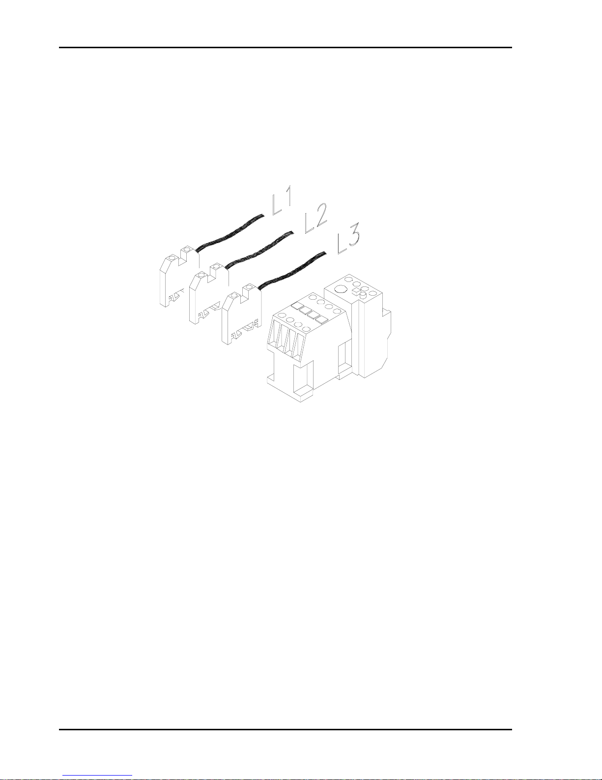
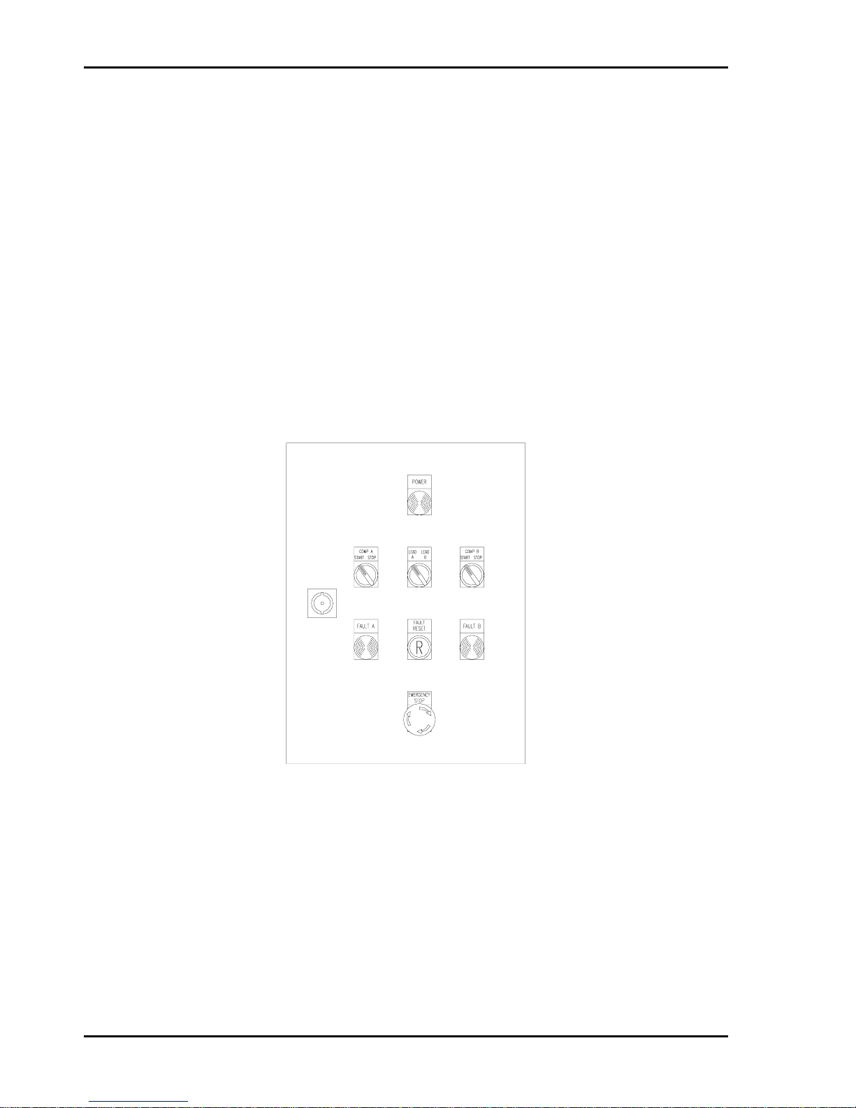
9.1.1 Central Control Box Operation.
The control box offers a number of configurations in which to operate the two
compressor units. (Refer Fig.5):
Fig. 5 - Control Panel, Central Contr ol Box
Page 27

Champion Compressors Ltd. Manual No. 975203 Rev H
21
‘Compressor A or Compressor B’ - Set the “A / B / AB” selector switch to
either ‘A’ or ‘B’ to run one compressor only. The other compressor will not
run, it can be switched to run in the event of the primary compressor being out
of service, i.e. a true ‘Duty / Standby’ application.
‘Compressor A and
Compressor B’ - Set the “A / B / AB” selector switch to
‘AB’ to supply power to both compressor units. The compressors will now run
in Lead / Lag mode, with the ‘Lead A / Lead B’ selector switch determining
which compressor will supply the base air supply for the demand. As stated
above, the Lead and Lag functions should be alternated between the two units
by regularly reversing the selector switches on a periodic (daily or weekly)
basis.
Note : The control box does not have the facility to set both units to Lead or
both to Lag. This configuration is neither useful or advisable.
‘Local or Remote Control’ - Set the “LOCAL / REM” Selector switch for each
compressor unit to start or stop the machine either locally or at a remote
location. (Refer Electrical Circuit Diagram at rear of manual).
The “EMERGENCY STOP” button will isolate power from both compressors
irrespective of the control mode selected.
Page 28
Champion Compressors Ltd. Manual No. 975203 Rev H
22
9.2 Lead/Lag Control.
Similar to the central control box, a pair of compressors may be controlled by
a lead/lag control box, equipping the package with ‘lead / lag’ capability.
Lead/Lag controls allow two compressors to operate in tandem. One unit is
selected to be the lead unit and the other the lag unit. In this situation, the
lead unit will provide the base air supply for the plant requirement. The lag
unit will provide any additional air as required during peak demands. The lead
and lag functions should be alternated between the two units by regularly
reversing the selector switch on a periodic (daily or weekly) basis.
9.2.1 Lead / Lag Control Box Operation.
The lead / lag control box offers lead / lag only in which to operate the two
compressor units. (Refer Fig.6):
Fig. 6 - Control Panel, Lead/Lag Control Box
The ‘Lead A / Lead B’ selector switch determines which compressor will
supply the base air supply for the demand. As stated above, the Lead and
Lag functions should be alternated between the two units by regularly
reversing the selector switches on a periodic (daily or weekly) basis.
Individual Start / Stop selector switches enable electrical isolation of the
motors only of one or both units.
Page 29

Champion Compressors Ltd. Manual No. 975203 Rev H
23
When a fault is detected, or the Emergency Stop button is depressed, the
machine will not start until the fault is removed and the Fault Reset button is
pressed.
9.3 Lead / Lag Pressure Switches
The central and lead / lag control boxes contain two pressure switches, (lead
and lag), which have been factory set as listed below.
Lead / Lag Pressure Switch Settings
Nominal Operating
Pressure
(kPa)
Nominal Pressure
Differential
(kPa)
Lead
Load
Pressure
(kPa)
Lead
Unload
Pressure
(kPa)
Lag
Load
Pressure
(kPa)
Lag
Unload
Pressure
(kPa)
780 80 700 780 650 730
1000 80 920 1000 870 950
If the settings have “drifted” during transport, it will be necessary to adjust
them on site. This is accomplished as follows (refer Figure 7):
1. (a) To increase pressure - turn range screw anticlockwise
(b) To reduce pressure - turn range screw clockwise
2. (a) To increase differential - turn differential screw clockwise
(b) To reduce differential - turn differential screw anticlockwise
For safety reasons, under no circumstances adjust the setting differently
to the ones listed above. If different pressure settings are required refer
Champion Compressors.
Fig. 7 - Control Pressure Switch (Central Control Box)
Page 30

Champion Compressors Ltd. Manual No. 975203 Rev H
24
9.4 Acoustic Hood (Ci 40/55).
The Ci 40/55 Dominators are available with an acoustic hood. This cabinet
helps to reduce the noise level, as well as acting as a protective cover for the
compressor. Ci75 / 110 models have the hoods fitted as standard.
9.5 Clean Air Pack (Dryer).
The clean air pack provides clean, moisture free air. A refrigerant dryer is
teamed in series with a microcoalescent filter or filters to remove any moisture
and oil carry-over in the discharge air supply.
NOTE: A 240V connection must be available for wiring of the refrigerant
dryer. The dryer must be individually wired to the supply, as it is not hardwired to the compressor electrics.
9.6 Dirty Environment Filter (Cyclopac).
For operation in dirty environments, a heavy-duty Cyclonic air filter is offered
as an externally mounted option. (Refer Section 18).
9.7 No Neutral & Hour-meter (Ci 40/55/75)
Where no neutral facility exists at the installation location, the no neutral
option may be fitted, allowing connection with three phase power leads and an
earth lead. Also included is an hour meter to record hours run, not standard
on Ci40 / 55. As stated above, if a refrigerant dryer is incorporated, a 240V
connection for single phase power supply to the dryer is necessary.
9.8 Duplex
The Duplex is a pair of Dominators mounted on a common twin air receiver,
approximately three times the volume of a standard air receiver. The
compressor units are controlled by either the 'Lead / Lag' Control box
providing ‘lead / lag’ operation (Refer Section 9.2) or the ‘Lead / Lag, Remote
Monitoring and Control’ box providing ‘duty / standby’ or ‘lead / lag’ operation
(Refer Section 9.1).
Page 31

Champion Compressors Ltd. Manual No. 975203 Rev H
25
When incorporated with the Clean Air Pack, the receivers will operate in a ‘wet
and dry’ configuration, i.e. two individual receivers separated by dryer /
filter(s). Discharge air enters the ‘wet’ receiver where some condensation
takes place, additional filtration is provided by the dryer / filter(s) before
entering the ‘dry’ receiver. An additional filter may be fitted at the discharge of
the ‘dry’ receiver.
The Dirty Environment Filter and Acoustic Hood (Ci 40 / 55) options are
available in conjunction with the Duplex option.
9.9 Base-mount
Where an air receiver or equivalent exists at the installation location, a
Dominator may be ordered without an integrated receiver. The pressure
switch is supplied loose (on a 2m fly lead) to be fitted into the air supply to
provide a control signal for correct compressor operation.
9.10 Sump Heater and Thermal Fan
A sump heater is available to enable the machine to stay warm when not in
operation and to prevent condensation from mixing with oil. This option is
advisable in the cases of a low load cycle, low ambient temperature and a
humid environment. The sump heater option requires a dedicated 240V
connection.
The thermal fan switch option is designed to suit machines with very low load
cycle operation. A temperature switch monitors oil temperature and only
switches the cooling fan on when the oil is at a minimum temperature. This
ensures the compressor achieves desired operating temperatures within a
minimum time.
9.11 Auto Restart Option
The auto restart option allows the machine to automatically restart after a 30
second delay upon the reinstatement of power following a power interruption.
9.12 Phase Failure Relay (Ci 75/110 only)
The phase failure relay option can be fitted to provide protection against
phase imbalance, phase dropout and incorrect phase sequence.
Page 32

Champion Compressors Ltd. Manual No. 975203 Rev H
26
10.0 MAINTENANCE
10.1 General
Your Dominator air compressor will give years of trouble free performance if
you ensure that it is correctly maintained. Proper maintenance will increase
the productive life of the unit and can result in large savings as a direct result
of reduced down time.
Champion Compressors offers a variety of Maintenance Management
solutions which provide regular maintenance to ensure long life and trouble
free service from your compressor. Contact your Champion Compressors
representative to arrange this service.
10.2 Daily Operation
Prior to starting drain any water from oil sump through drain valve until oil
begins to flow (Oil floats on water).
Check the oil level via the appropriate sight glass located on the integrated
screw.
Drain any water from receiver(s) where applicable.
Page 33

Champion Compressors Ltd. Manual No. 975203 Rev H
27
10.3 Maintenance Schedule
Refer to Section 2 and the ‘Parts section’ for all part numbers of items
mentioned here.
10.3.1 Initial Service - 250 hours
The oil should be changed after the first 250 hours of service, and then after
every 1,500* hours of service. Use only Champion recommended oil. (See
Section 6 for 'Recommended Lubricants')
10.3.2 Every 1,500 Hours
Change the compressor oil and oil filter (use prescribed grade only)*.
Replace the air intake filter element.
Check & adjust the belt tension. Replace as required.
Check purge line recovery pipe for blockage by observing the purge line sight
glass. If no flow is visible, the purge line should be inspected and unblocked.
Access is gained by removing the purge line sight glass.
Drain all air receivers.
* Except with long-life lubricant (synthetic), analyse sample and change if
required.
10.3.3 Every 3,000 Hours (Or Yearly)
Perform all checks listed for ‘Every 1,500 hours’ as well as the following:
Replace separator element.
Check condition of inlet controller, service if necessary.
Check condition of Minimum Pressure Valve, service if necessary.
Check condition of Thermo By-pass Valve, service if necessary.
Check that all electrical connections are tight.
Inspect all
safety devices.
Check general tightness of nuts, bolts and pipe fittings.
Check condition of Microfilter Element, replace if necessary. (Where Fitted)
WARNING - Do not attempt any maintenance when the compressor is
running or pressurised. Stop the compressor, relieve all internal
pressure and isolate the power supply before per f or ming maintenance.
Page 34

Champion Compressors Ltd. Manual No. 975203 Rev H
28
THIS PAGE HAS BEEN
LEFT BLANK
Page 35

Champion Compressors Ltd. Manual No. 975203 Rev H
29
A.R. = As Required
N.S.S. = Not Sold Separately
Page 36

Champion Compressors Ltd. Manual No. 975203 Rev H
30
11.0 GENERAL ASSEMBLY COMPONENTS - Ci 40 / 55
Page 37

Champion Compressors Ltd. Manual No. 975203 Rev H
31
11.0 GENERAL ASSEMBLY COMPONENTS - Ci 40 / 55 - (9800660 Rev G)
Item Part No. Description Qty.
1 511132 Air Receiver - 380 Dia x 1200 Long 1
2 872267 Belt Guard - 500 x 250 x 85 1
3 872364 Bracket - Belt Guard - 245 x 150 x 15 1
4 741061 Pressure Switch - MDR3RM - Ci 40 - 7 & 10 bar 1
741062 Pressure Switch - MDR3RM - Ci 55 - 7 & 10 bar 1
741049 Pressure Switch - MDR3RM - Ci 40 - 13 bar 1
740150 Pressure Switch - MDR3RM - Ci 55 - 13 bar 1
5 521295 Platform W.A. - 745 X 320 X 120 1
6 491390 Cooler / Fan Assembly - Oil 1
6a 491399 Cooler - Part of Item 6 1
6b 481236 Fan - Part of Item 6 1
Motors - 380/415 50Hz, 440V 60Hz
7 351253 Motor - 5.5 kW - 2P - IP55 - TOP - Multivoltage - Ci 55 1
351276 Motor - 4.0 kW - 2P - IP55 - TOP - Multivoltage - Ci 40 1
8 301023 Integrated Screw - Ci 40 & 55 1
9 681718 Hose Assy - 3/8” - Cooler to Airend Oil Injection 1
9a N.S.S Elbow - 9/16” JIC x 1/2” BSPP - Part of Item 9 1
9b N.S.S Nipple - 9/16” JIC x 3/8” BSPP - Part of Item 9 1
10 681717 Hose Assy - 3/8” - Airend Oil Discharge to Cooler 1
10a N.S.S Elbow - 9/16” JIC x 1/2” BSPP - Par t of Item 10 1
10b N.S.S Nipple - 9/16” JIC x 3/8” BSPT - Part of Item 10 1
11 681495 Hose Assy - 1/2” - Airend Air Discharge to Receiver 1
11a N.S.S Nipple - 3/4” JIC x 1/2” BSPT - Part of Item 11 2
12 601079 Taptite - M6 x 16 A.R
13 601037 Bolt - Hex Hd - M10 x 30 12
14 601091 Washer - M10 Mudguard 8
15 601086 Washer - M10 Spring 4
16 621010 Plug - Hex - Gal - ¼” BSP 2
17 371004 Clamp Plate - Motor - Ci 55 2
371005 Clamp Plate - Motor - Ci 40 2
18 721029 Over Temperature Switch - Oil Cooler - IP65 1
19 621066 Plug - Hex - Black - 1/2” BSPT 1
20 671004 Dowty Seal - 1/2” 1
21 601009 Washer - M10 Flat 8
22 781002 Gauge - Air Pressure - 63 Dia / 1600 kPa 1
23 541268 Valve - Safety - 1335 kPa - 1/4” BSP 1
24 601395 Grommet - 16mm 1
25 541025 Gate Valve - 3/4” 1
26 621469 Nipple - Gal - Hex Red - 1.1/2” BSPT x 3/4” BSPT 1
27 601053 Bolt - M12 x 75 - Tensioner Adjustment - Ci 55 3
601282 Bolt - M12 x 100 - Tensioner Adjustment - Ci 40 1
28 601007 Nut - ZP - M10 4
29 601017 Nut - Nyloc - M10 4
30 711079 Gland - PVC - M20 2
31 541173 Valve - Ball - 1/4"BSP M & F 1
32 711078 Reducer - PVC - 25 to 20mm 1
33 621571 Adaptor - Swivel - ¼” BSPF x 1/4” BSPM 1
33a 621609 Nipple - Hex - plt - ¼" BSPT - Seated 30 deg 1
Page 38

Champion Compressors Ltd. Manual No. 975203 Rev H
32
11.0 GENERAL ASSEMBLY COMPONENTS - Ci 40 / 55
(Continued)
Page 39

Champion Compressors Ltd. Manual No. 975203 Rev H
33
11.0 GENERAL ASSEMBLY COMPONENTS- Ci 40 / 55 (9800660 Rev G) - Continued
Item Part No. Description Qty.
Airend Pulleys
34 401312 Pulley - 2 SPZ x 106 - 1610 T/L - Ci 40 - 7 & 10 bar 1
401284 Pulley - 2 SPZ x 118 - 1610 T/L - Ci 40 - 13 bar 1
401304 Pulley - 2 SPZ x 95 - 1610 T/L - Ci 55 - 7,10 & 13 bar 1
35 411036 Taperlock Bush - Airend - 1610-25 - Ci 40 & 55 1
35a N.S.S Grub Screw - Part of Item 33 2
Motor Pulleys
36 401304 Pulley - 2 SPZ x 95 - 1610 T/L - Ci 40 - 7,10 & 13 bar 1
401312 Pulley - 2 SPZ x 106 - 1610 T/L - Ci 55 - 13 bar 1
401284 Pulley - 2 SPZ x 118 - 1610 T/L - Ci 55 - 7 & 10 bar 1
37 411172 Taperlock Bush - Motor - 1610-28 - Ci 40 1
411164 Taperlock Bush - Motor - 1610-38 - Ci 55 1
37a N.S.S Grub Screw - Part of Item 32 2
38 421101 Vee Belt - XPZ 937 - 7,10 & 13 bar 2
39 712331 Sleeving - Black - 10mm A.R.
40 631173 Bush - Reducing - ½"BSP M to 1/4"BSP F 1
Page 40

Champion Compressors Ltd. Manual No. 975203 Rev H
34
12.0 GENERAL ASSEMBLY COMPONENTS- Ci 75
Page 41

Champion Compressors Ltd. Manual No. 975203 Rev H
35
12.0 GENERAL ASSEMBLY COMPONENTS - Ci 75 - (9800657 Rev H)
Item Part No. Description Qty.
1 511135 Air Receiver 1
2 301020 Airend - Integrated Screw 1
Motors - 380/415 V 50 Hz, 440V 60Hz
3 351274 Motor - 7.5kW - 2P - TOP - IP55 - Multivoltage 1
4 491394 Cooler / Fan Assembly - Air / Oil - Emmegi 1
4a 491398 Cooler - Part of Item 4 1
4b 481235 Fan - Part of Item 4 1
5 521321 Platform W.A. 1
6 621609 Nipple - 1/4” BSPT - 30 deg Seated 1
7 601091 Washer - ZP - M10 Mudguard 4
8 681695 Hose Assembly - 1/2” - Oil Cooler to Airend Oil
Injection
1
8a N.S.S Elbow - 3/4” JIC x 1/2” BSPP 1
8b N.S.S Nipple - 3/4” JIC x 1/2” BSPP 1
9 681534 Hose Assembly - 3/4” - Airend Discharge 1
9a N.S.S Elbow - 1.1/16 JIC x 3/4” BSPT 1
9b N.S.S Elbow - 1.1/16 JIC x 1/2” BSPT 1
10 681654 Hose Assembly - 3/4” - Air Aftercooler to Receiver 1
10a N.S.S Nipple - 1” BSPT x 1” BSPT 1
10b N.S.S Elbow - 1.1/16” JIC x 3/4” BSPT 1
11 681696 Hose Assembly - 1/2” - Oil Discharge to Cooler Inlet 1
11a N.S.S Elbow - 3/4” JIC x 1/2” BSPP 1
11b N.S.S Nipple - 9/16” JIC x 1/2” BSPP 1
12 872539 Panel - Belt Guard Cover 1
15 601037 Bolt - Hex Hd - M10 x 30 8
16 872538 Panel - Belt Guard 1
17 872442 Angle - Door 2
18 872391 Panel - Rear 1
19 872313 Panel - Compressor Lid 1
20 872315 Panel - Door 1
21 872390 Panel - Front 1
22 601079 T aptite - M6 x 16 A.R
23 781009 Hour Meter - 48 Sq. - 240V 1
23a N.S.S Bracket - Hourmeter 1
24 9800673-4 Sound Foam - Front Panel - Cut Out 1
25 9800673-3 Sound Foam - Front Panel - Large 1
26 9800673-2 Sound Foam - Front Panel - Small 1
27 741063 Pressure Switch - MDR 3RM- 7 & 10 bar 1
741056 Pressure Switch-MDR 3RM - 13 bar 1
28a 861018 Seal Strip - 15 mm wide 2
28b 861018 Seal Strip - 15 mm wide 2
29 861035 Door Catch Kit - Black - 1000-V349 1
30 601086 Washer - ZP - Spring - M10 8
31 721029 Over Temperature Switch - Oil Cooler - IP65 1
Page 42

Champion Compressors Ltd. Manual No. 975203 Rev H
36
12.0 GENERAL ASSEMBLY COMPONENTS- Ci 75
(Continued)
Page 43

Champion Compressors Ltd. Manual No. 975203 Rev H
37
12.0 GENERAL ASSEMBLY COMPONENTS - Ci 75 - (9800657 Rev H) - Continued
Item Part No. Description Qty.
32 9800673-5 Sound Foam - Roof Panel - Rear 1
33 9800673-7 Sound Foam - Roof Panel - Front 1
34 9800673-1 Sound Foam - Rear Panel 1
35 541173 Valve - Ball - 1/4"BSP M & F 2
36 631173 Bush - Reducing - 1/2"BSP M to 1/4"BSP F 2
37 9800673-8 Sound Foam - Right End Panels 2
38 9800673-6 Sound Foam - Service Door 1
39 9800673-9 Sound Foam - Lef t End Panels 2
40 371004 Clamp Plate - Motor 2
44 601007 Nut - ZP - M10 4
45 861089 Handle - Pocket - Ci Series 2
46 601129 Nut - Nyloc - M10 4
47 601007 Washer - Flat - M10 8
48 621220 Nipple - Gal - 1” 1
49 541026 Gate Valve - 1” BSP 1
50 621067 Plug - Hex Blk - 3/4” BSPT 1
51 621064 Plug - Hex Blk - 1/8” BSPT 2
52 781002 Gauge - Air Pressure - 63 Dia/1600 kPa - Rear Entry 1
53 601053 Bolt - ZP - M12 x 75 2
54 601282 Bolt - ZP - M12 x 100 2
58 541268 Valve - Safety - 1/4” BSP - 1335 kPa - 6mm orifice 1
59 601395 Grommet - 16mm 1
60 621571 Adaptor - Swivel - 1/4” BSPF x 1/4” BSPM 1
61 711078 Reducer - PVC - 25/20 2
62 711079 Cable Gland - PVC - M20 2
63 601035 Bolt - Hex Hd - M10 x 20 4
Motor Pulleys
70 401313 Pulley - 2 SPZ x 160 PD - 2012 T/L 1
Airend Pulleys
71 401319 Pulley - 2 SPZ x 112 PD - 1610 T/L - 7 bar 1
401315 Pulley - 2 SPZ x 125 PD - 1610 T/L - 10 bar 1
401307 Pulley - 2 SPZ x 132 PD - 1610 T/L - 13 bar 1
72 421107 Vee Belt - XPZ1080 2
73 411002 Taperlock - Motor - 1210-38 1
73a N.S.S Grub Screw - Part of Item 63 2
74 411036 Taperlock - Airend - 1610-25 1
74a N.S.S Grub Screw - Part of Item 74 2
Star Delta Option (replaces items 19, 28, 32, 33 &
45)
75 872441 Panel - Compressor Top 1
Page 44

Champion Compressors Ltd. Manual No. 975203 Rev H
38
12.0 GENERAL ASSEMBLY COMPONENTS- Ci 75
(Continued)
Page 45

Champion Compressors Ltd. Manual No. 975203 Rev H
39
12.0 GENERAL ASSEMBLY COMPONENTS - Ci 75 - (9800657 Rev H) - Continued
Item Part No. Description Qty.
76 861018 Seal Strip - 15mm wide A.R
77 861089 Handle - Pocket - Ci Series 1
78 861099 Gas Strut - 200N - 210 Stroke 1
79 872440 Panel - Electrical Door 1
80 9800747-5 Sound Foam - Roof Panel - Front 2
81 9800747-3 Sound Foam - Roof Panel - Top Large 2
82 9800747-9 Sound Foam - Roof Panel - Top Small 1
Page 46

Champion Compressors Ltd. Manual No. 975203 Rev H
40
13.0 GENERAL ASSEMBLY COMPONENTS- Ci 110
Page 47

Champion Compressors Ltd. Manual No. 975203 Rev H
41
13.0 GENERAL ASSEMBLY COMPONENTS - Ci 110 - (9800745 Rev E)
Item Part No. Description Qty.
1 511135 Air Receiver 1
2 301020 Airend - Integrated Screw 1
Motors - 380/415/440 V 50 Hz, 440V 60Hz
3 351259 Motor - 11kW - 2P - TOP- IP55 - Multivoltage 1
4 491394 Cooler / Fan Assembly - Air / Oil - Emmegi 1
4a 491398 Cooler - Part of Item 4 1
4b 481235 Fan - Part of Item 4 1
5 521302 Platform W.A 1
6 872441 Panel - Compressor Top 1
7 872391 Panel - Rear 1
8 872390 Panel - Front 1
9 872538 Panel - Belt Guard 1
10 872539 Panel - Belt Guard Cover 1
11 872315 Panel - Door 1
12 872440 Panel - Electrical Door 1
13 872316 Angle - Door 2
14 861076 Hinge Set 2
15 861035 Door Catch Kit - Black - 1000-V349 1
16 9800747-5 Sound Foam - Roof Panel - Front 1
17 9800747-3 Sound Foam - Roof Panel - Top Large 1
18 9800747-9 Sound Foam - Roof Panel - Top Small 1
19 9800747-6 Sound Foam - Right End Panels 2
20 9800747-7 Sound Foam - Left End Panels 2
21 9800747-4 Sound Foam - Service Door 1
22 9800747-1 Sound Foam - Rear Panel 1
23 9800747-2 Sound Foam - Front Panel - Cut Out 1
23a 9800747-8 Sound Foam - Front Panel - Large 1
24 9800747-10 Sound Foam - Front Panel - Small 1
25 601091 Washer - ZP - M10 Mudguard 4
26 601053 Bolt - ZP - M12 x 75 2
27 601007 Nut - ZP - M10 4
28 601129 Nut - Nyloc - M10 4
29 601007 Washer - Flat - M10 8
30 891089 Handle - Pocket Compressor Cover 1
31a 861018 Seal Strip - 15 mm wide 2
31b 861018 Seal Strip - 15 mm wide 2
32 421107 Vee Belt - XPZ1080 - Ci 75/110 - All pressures 2
33 861099 Gas Strut - 200 N - 210 Stroke 1
34 621067 Plug - Hex Blk - 3/4” BSPT 1
35 371007 Clamp Plate - Motor - 254 mm 2
36 541268 Valve - Safety - 1/4” BSP - 1335 kPa - 6mm orifice 1
37 721029 Over Temperature Switch - Oil Cooler - IP65 1
38 541173 Valve - Ball - 1/4"BSP M & F 2
Page 48

Champion Compressors Ltd. Manual No. 975203 Rev H
42
13.0 GENERAL ASSEMBLY COMPONENTS - Ci 110
(Continued)
Page 49

Champion Compressors Ltd. Manual No. 975203 Rev H
43
13.0 GENERAL ASSEMBLY COMPONENTS - Ci 110 - (9800745 Rev E) - Continued
Item Part No. Description Qty.
38a 631173 Bush - Reducing - 1/2"BSP M to 1/4"BSP F 2
39 541026 Gate Valve - 1” BSP 1
40 621220 Nipple - Gal - 1” 1
41 621064 Plug - Hex Blk - 1/8” BSPT 2
42 681596 Hose Assembly - 1/2” - Oil Cooler to Airend Oil
Injection
1
42a N.S.S Elbow - 3/4” JIC x 1/2” BSPP 1
42b N.S.S Nipple - 3/4” JIC x 1/2” BSPP 1
43 681534 Hose Assembly - 3/4” - Airend Discharge 1
43a N.S.S Elbow - 1.1/16 JIC x 3/4” BSPT 1
43b N.S.S Elbow - 3/4” JIC x 1/2” BSPP 1
44 681533 Hose Assembly - 3/4” - Air Aftercooler to Receiver 1
44a N.S.S Nipple - 1” BSPT x 1” BSPT 1
44b N.S.S Elbow - 1.1/16” JIC x 3/4” BSPT 1
45 681535 Hose Assembly - 1/2” - Oil Discharge to Cooler Inlet 1
45a N.S.S Nipple - 9/16” JIC x 1/2” BSPT 1
45b N.S.S Nipple - 9/16” JIC x 1/2” BSPP 1
46 741005 Pressure Switch - XMP 1
741013 Pressure Switch - XMP - 13 bar 1
47 621609 Nipple - 1/4” BSPT 2
48 621011 Tee - Gal - 1/4” BSP 1
49 781002 Gauge - Air Pressure - 63 Dia/1600 kPa - Rear
Entry
1
50 621571 Adaptor - Swivel - 1/4” BSPF x 1/4” BSPM 1
51 601079 Taptite - M6 x 16 A.R
52 601037 Bolt - Hex Hd - M10 x 30 8
53 601035 Bolt - Hex Hd - M10 x 20 4
54 601086 Washer - ZP - Spring - M10 8
55 711263 Reducer - PVC - 32/25 2
56 711078 Reducer - PVC - 25/20 2
57 711079 Cable Gland - PVC - M20 2
Airend Pulleys
58 401318 Pulley - 2 SPZ x 90 PD - 1610 T/L - 7 bar 1
401314 Pulley - 2 SPZ x 100 PD - 1610 T/L - 10 bar 1
401312 Pulley - 2 SPZ x 106 PD - 1610 T/L - 13 bar 1
59 411036 Taperlock - Airend - 1610-25 1
59a N.S.S Grub Screw - Part of Item 59 2
Motor Pulleys
60 401305 Pulley - 2 SPZ x 180 PD - 2012 T/L 1
61 411032 Taperlock - Motor - 1210-42 1
61a N.S.S Grub Screw - Part of Item 61 2
Page 50

Champion Compressors Ltd. Manual No. 975203 Rev H
44
14.0 INTEGRATED SCREW COMPONENTS- Ci 40 / 55
Page 51

Champion Compressors Ltd. Manual No. 975203 Rev H
45
14.0 INTEGRATED SCREW COMPONENTS - Ci 40 / 55 (98001013 Rev A)
Item Part No. Description Qty.
1 301023 Airend - Integrated Screw 1
2 278780 Sight Glass - Oil 2
3 N.S.S. Cap Screw 4
4 621064 Plug - 1/8” BSP Black 2
5 N.S.S. Grub Screw - 3/8” BSP 1
6 541113 Oil Drain Tap - 3/8” BSP 1
7 278905 Inlet Controller Kit 1
8 278766 Element - Air Filter 1
9 278773 Element - Separator - Spin On 1
10 N.S.S. Cover - Air Filter 1
11 278879 Oil Return Orifice 1
12 278783 Safety Valve - Integrated Screw - 1500 kPa - Ci
Series
1
13 278664 Solenoid Valve - 240V - H Class Coil 1
14 278780 Sight Glass - Purge Line - Part of Sight Glass Kit 1
15 278775 Minimum Pressure Valve 1
16 N.S.S. Oil Filler Cap 1
17 N.S.S. Element - Thermovalve - 70º C 1
N.S.S. Element - Thermovalve - 80º C - Export 1
18 N.S.S. O-ring 1
19 N.S.S. Cover - Thermovalve 1
20 N.S.S. Slide - Thermovalve 1
21 N.S.S. Spring 1
22 278877 Element - Oil Filter Cartridge 1
23 N.S.S. Oil Filter Base 1
24 N.S.S. O-ring 1
25 N.S.S. O-ring 1
26 N.S.S. O-ring 1
27 N.S.S. Copper Washer 2
28 N.S.S. Copper Washer 1
29 N.S.S. Copper Washer 1
30 278859 Gasket - Inlet VV - Lower 1
31 278858 Gasket - Inlet VV - Upper 1
32 N.S.S. Plug 1
Repair Kits
278875 Kit - Thermovalve 70º-Includes Items 17,18, 20 1
278876 Kit - Thermovalve 80º-Includes Items 17,18, 20 1
278763 Kit - Airend Seals Ci 40-110 1
278874 Kit - O-rings - Includes Items 18, 24, 25, 26 1
Page 52

Champion Compressors Ltd. Manual No. 975203 Rev H
46
15.0 INTEGRATED SCREW COMPONENTS- Ci 75 / 110
Page 53

Champion Compressors Ltd. Manual No. 975203 Rev H
47
15.0 INTEGRATED SCREW COMPONENTS - Ci 75 / 110 - (9800879 - Rev A)
Item Part No. Description Qty.
1 301020 Airend - Integrated Screw 1
2 278780 Sight Glass - Oil 2
3 N.S.S. Cap Screw 4
4 621064 Plug - 1/8” BSP Black 2
5 N.S.S. Grub Screw - 3/8” BSP 1
6 541113 Oil Drain Tap - 3/8” BSP 1
7 278830 Inlet Controller Kit 1
8 278767 Element - Air Filter 1
9 278765 Element - Separator - Spin On 1
10 N.S.S. Cover - Air Filter 1
11 601163 Wing Nut - M6 1
12 278783 Safety Valve - Integrated Screw - 1500 kPa - Ci
Series
1
13 278770 Solenoid Valve - 240V - H Class Coil 1
14 278780 Sight Glass - Purge Line - Part of Sight Glass Kit 1
15 278775 Minimum Pressure Valve 1
16 N.S.S. Oil Filler Cap 1
17 N.S.S. Element - Thermovalve - 70º C 1
N.S.S. Element - Thermovalve - 80º C - Export 1
18 N.S.S. O-ring 1
19 N.S.S. Cover - Thermovalve 1
20 N.S.S. Slide - Thermovalve 1
21 N.S.S. Spring 1
22 278877 Element - Oil Filter Cartridge 1
23 N.S.S. Oil Filter Base 1
24 N.S.S. O-ring 1
25 N.S.S. O-ring 1
26 N.S.S. O-ring 1
27 N.S.S. Copper Washer 2
28 N.S.S. Copper Washer 1
29 N.S.S. Copper Washer 1
30 278859 Gasket - Inlet VV - Lower 1
31 278858 Gasket - Inlet VV - Upper 1
32 671155 O-ring - BS137 Viton 1
33 671156 O-ring - BS012 Viton 1
34 N.S.S. Plug 1
35 278879 Oil Return Orifice 1
Repair Kits
278875 Kit - Thermovalve 70º-Includes Items 17,18, 20 1
278876 Kit - Thermovalve 80º-Includes Items 17,18, 20 1
278763 Kit - Airend Seals Ci 40-110 1
278874 Kit - O-rings - Includes Items 18, 24, 25, 26 1
Page 54

Champion Compressors Ltd. Manual No. 975203 Rev H
48
16.0 ELECTRICAL STARTER ASSEMBLY - Ci75SD/110
Page 55

Champion Compressors Ltd. Manual No. 975203 Rev H
49
16.0 ELECTRICAL STARTER ASSEMBLY - Ci75SD / 110 - (9800746 Rev C)
Item Part No. Description Qty.
Internal Electrical
1 712184 Transformer - 415/240V - 60 VA 1
712396 Transformer - 60VA Multi-Input To 240V - Export
Option Only
1
2 712116 Timer - Run On Timer - Off Delay - Mode D 1
3 711063 Relay Base - 2 Pole 2
711063 Relay Base - 2 Pole - Auto Start Option 1
712247 Relay Base - 8 Pin - Auto Start Option 1
4 711062 Relay - 240V AC - 2 Pole 2
711062 Relay - 240V AC - 2 Pole - Auto Start Option 1
712218 Relay - 240V AC - Latching - Auto Start Option 1
5 712359 Phase Failure Relay - Export Option 1
6 712116 Timer - Auto Start - Mode A - Auto Start Option 1
7 711349 Terminal Block - Earth 2
8 711048 Terminal Block 4
9 601079 Taptite - M6 X 16 2
10 711137 Din Rail - 35 x 8 - Omega A.R.
11 712029 Contactor - Line/Delta - CL03 - A301MR - GE 2
12 712044 Overload - 10-16 A - GE - Ci 110 1
712043 Overload - 8-12 A - GE - Ci 75SD 1
13 712205 Interlock - Mechanical - Electrical - bela 1
14 712027 Contactor - Star - CL02 - A301TR - GE 1
15 712162 Timer - Star Delta 1
16 711075 Fuse Holder 3
17 N.S.S Cover - Fuse Holder - Part of Item 17 3
18 711222 Fuse Link - 4A 1
19 711221 Fuse Link - 2 A 2
20 711075 Fuse Holder - Export Option 1
21 N.S.S Cover - Fuse Holder - Part of Item 4 - Export Option 1
22 711221 Fuse Link - 2A - Export Option 1
23 711221 Fuse Link - 2A - Heater Pad Option 1
24 712255 Terminal Block - Suit 4 mm Cable 3
25 711048 Terminal Block - Heater Pad Option 4
26 711046 Terminal End Cover 2
711046 Terminal End Cover - Heater Pad Option 1
27 711462 Cable Gland - M16 4
27a N.S.S. Nut - Cable Gland 4
28 711079 Cable Gland - M20 2
28a N.S.S. Nut - Cable Gland 2
29 711140 Duct - Grey PVC - 30 x 60 A.R
29a N.S.S. Duct - Grey PVC - Cover A.R
External Electrical
30 712157 Contact Block - Power Supply 1
31 712002 Contactor - N/O 2
32 712003 Contactor - N/C 3
Page 56

Champion Compressors Ltd. Manual No. 975203 Rev H
50
16.0 ELECTRICAL STARTER ASSEMBLY - Ci75SD/110
(Continued)
Page 57

Champion Compressors Ltd. Manual No. 975203 Rev H
51
16.0 ELECTRICAL STARTER ASSEMBLY - Ci75SD / 110 - (9800746 Rev C) Continued
Item Part No. Description Qty.
33 712004 Emergency Stop Button 1
33a N.S.S Locknut - Button 1
34 712067 On/Off Switch - 2 Position 1
34a N.S.S Locknut - Button 1
35 712160 Reset Button - Auto Restart Option 1
35a N.S.S Locknut - Button 1
36 781009 Hour Meter 1
36a N.S.S. Hour Meter Bracket 1
37 671139 Gasket Hour Meter 1
Page 58

Champion Compressors Ltd. Manual No. 975203 Rev H
52
17.0 CLEAN AIR PACK ASSEMBLIES
Page 59

Champion Compressors Ltd. Manual No. 975203 Rev H
53
17.0 CLEAN AIR PACK ASSEMBLIES - (9800668 Rev E)
Item Part No. Description Qty.
Clean Air Pack Components - Ci 40 & Ci 55
*1 182006 Refrigerated Dryer - Champion CRD006 1
182009 Refrigerated Dryer - Champion CRD009 1
2 521326 Mount W.A - Dryer 2
521329 Mount W.A - Dryer 2
3 681699 Hose Assy - ¾” - Receiver to Dryer 1
3a N.S.S Nipple - 3/8” BSPT x ½” BSPT - Part of Item 3 1
3b N.S.S Elbow - ½” BSP x ¾” JIC - Part of Item 3 1
4 211556 Micro Filter - Champion G5ZD 1
211756 G5ZD Filter Element 1
5 621561 Nipple - Hex Red - 3/8” BSPT x ½” BSPT -
CRD009
1
621700 Nipple - Hex - 3/8” BSPT - CRD006 1
6 621559 Elbow - ½” BSPF Swivel x ½” BSPT - CRD009 1
621819 Elbow -3/8” BSPF Swivel x 3/8” BSPT - CRD006 1
7 541025 Gate Valve - ¾” - CRD009 1
541024 Gate Valve - ½” - CRD006 1
8 621562 Nipple - Hex Red - ¾” BSPT x ½” BSPT - CRD009 1
621561 Nipple - Hex Red - ½” BSPT x 3/8” BSPT -
CRD006
1
9 601147 Taptite - Hex - Washer Face - M8x36 4
10 601037 Bolt - M10 x 30 4
11 601091 Washer - M10 Mudguard 4
12 601086 Washer - M10 Spring 4
Clean Air Pack Components - Ci 75 & Ci 110
*15 182012 Refrigerated Dryer - Champion CRD012 1
182018 Refrigerated Dryer - Champion CRD018 1
16 521327 Dryer Mount W.A - CRD012 2
521328 Dryer Mount W.A - CRD018 2
17 681700 Hose Assy - ¾” 2
18 621593 Elbow - 1/2” BSPT X 1.1/16”JIC 2
19 621592 Elbow - ¾” BSPT X 1.1/16”JIC 1
20 621593 Elbow - 1/2” BSPT X 1.1/16”JIC - CRD012 1
621592 Elbow - ¾” BSPT X 1.1/16”JIC - CRD018 1
21 621562 Nipple - Hex Red - ¾” BSPT x ½” BSPT - CRD012 1
621566 Nipple - Hex Red - 1” BSPT x ¾” BSPT - CRD018 1
22 872540 Bracket - Micro Filter 1
23 601440 Screw - Socket Head - M8x110 2
24 601004 Washer - M8 Flat 2
25 601157 Nut - Nyloc - M8 2
26 601002 Taptite - Cross Recess - Pan Hd - M6 2
27 601037 Bolt - M10 x 30 4
28 601091 Washer - M10 Mudguard 4
*: For Service and spares instruction - Refer to separate dryer manual supplied with compressor
Page 60

Champion Compressors Ltd. Manual No. 975203 Rev H
54
17.0 CLEAN AIR PACK ASSEMBLIES
(Continued)
Page 61

Champion Compressors Ltd. Manual No. 975203 Rev H
55
17.0 CLEAN AIR PACK ASSEMBLIES - (9800668 Rev E) - Continued
29 601086 Washer - M10 Spring 4
30 601147 Taptite - Hex - Washer Face - M8x36 4
31 211560 Micro Filter - Champion G7ZD 1
211760 G7ZD Filter Element 1
32 541025 Gate Valve - ¾” - CRD012 1
541026 Gate Valve - 1” - CRD018 1
Various Filter Arrangements Available
211551 Micro Filter - Champion G3V
211751 G3V Filter Element
211552 Micro Filter - Champion G3ZP
211752 G3ZP Filter Element
211553 Micro Filter - Champion G3XP
211753 G3XP Filter Element
211554 Micro Filter - Champion G3A**
211754 G3A** Filter Element
211555 Micro Filter - Champion G5V
211755 G5V Filter Element
211556 Micro Filter - Champion G5ZP
211756 G5ZP Filter Element
211557 Micro Filter - Champion G5XP
211757 G5XP Filter Element
211558 Micro Filter - Champion G5A**
211758 G5A** Filter Element
211559 Micro Filter - Champion G7V
211759 G7V Filter Element
211560 Micro Filter - Champion G7ZP
211760 G7ZP Filter Element
211561 Micro Filter - Champion G7XP
211761 G7XP Filter Element
211562 Micro Filter - Champion G7A**
211762 G7A** Filter Element
*: For Service and spares instruction - Refer to separate dryer manual supplied with compressor
**: Series A filters are supplied with manual drain and no differential pressure gauge
Page 62

Champion Compressors Ltd. Manual No. 975203 Rev H
56
18.0 CYCLOPAC AIR INTAKE ASSEMBLIES
Page 63

Champion Compressors Ltd. Manual No. 975203 Rev H
57
18.0 CYCLOPAC AIR INTAKE ASSEMBLIES - (9800688 Rev D)
Item Part No. Description Qty.
Ci 40 - 55
1 561354 Clamp - Hose - Worm Drive - 40 to 60 mm 4
2 561096 Rubber - 90 Deg Elbow 1
3 681570 Tube - Aluminised - 2” - 300 X 270 1
4 681582 Hose - Rubber - 2” id x 105 Long 1
5 561051 Mounting Band - Cyclopac - 5.21 id 2
6 561049 Filter - Air - Cyclopac - FWA05-2526 1
6a N.S.S. Air Filter Body - 5” 1
6b 270092 Element - Air Filter - 5” 1
6c N.S.S. Filter Body Clamp 1
6d N.S.S. Standard Cup Assembly 1
7 601004 Washer - Flat - Zinc PL 4
8 601086 Washer - Spring - Zinc PL 4
9 601003 Nut - Hex - Zinc PL - M8 4
10 601006 Bolt - Hex Hd - Zinc PL - M8 x 20 4
11 631025 Tube Fitting - Str Conn - ¼” x 1/8” BSPM 1
12 681002 Tube - ¼” Nylon A.R.
13 631024 Tube Fitting - Elbow - ¼” x 1/8” BSPM 1
Ci 75 - 110
14 861077 Seal Strip - P. Mould - Nitrile 1
15 N.S.S. Air Filter Cover 1
16 561200 Clamp - Hose - Worm Drive - 35 to 53 mm 1
17 561354 Clamp - Hose - Worm Drive - 40 to 60 mm 3
18 561454 Reducer - Rubber - 2” to 1 ½” 1
19 681583 Tube - Aluminised - 2” - 80 x 80 1
20 681582 Hose - Rubber - 2” id x 80 Long 1
21 561049 Filter - Air - Cyclopac - FWA05-2526 1
21a N.S.S. Air Filter Inlet Hood 1
21b N.S.S. Air Filter Body - 5” 1
21c 270092 Element - Air Filter - 5” 1
21d N.S.S. Filter Body Clamp 1
21e N.S.S. Standard Cup Assembly 1
22 561051 Mounting Band - Cyclopac - 5.21 id 2
23 601006 Bolt - Hex Hd - Zinc PL - M8 x 20 4
24 601004 Washer - Flat - Zinc PL 4
25 601086 Washer - Spring - Zinc PL 4
26 601003 Nut - Hex - Zinc PL - M8 4
Page 64

Champion Compressors Ltd. Manual No. 975203 Rev H
58
19.0 ACOUSTIC HOOD ASSEMBLY
Page 65

Champion Compressors Ltd. Manual No. 975203 Rev H
59
19.0 ACOUSTIC HOOD ASSEMBLY - (9800689 Rev E)
Item Part No. Description Qty.
1 872557 Panel - Compressor Top - 820 x 570 x 100 1
2 872558 Panel - Rear 1
3 872349 Angle - Support - 20 x 20 x 2 - 474 Long 2
4 872364 Panel - Belt Guard - 580 x 125 x 100 1
5 872393 Panel - Front - 820 x 340 x 95 1
6 872416 Panel - Belt Guard Mounting 2
7 872417 Panel - Belt Guard Cover 1
8 601079 Taptite - Cross Recess Pan Head - M6 x 16 19
9 861018 Seal Strip - 15 mm wide A.R.
10 861089 Handle - Pocket - Ci Series 2
11 9800700-1 Sound Insulation Foam - 309 x 820 x 25 1
12 9800700-2 Sound Insulation Foam - 309 x 820 x 25 1
13 9800700-3 Sound Insulation Foam - 190 x 820 x 25 1
14 9800700-4 Sound Insulation Foam - 395 x 820 x 25 1
Page 66

Champion Compressors Ltd. Manual No. 975203 Rev H
60
20.0 AUTODRAIN ASSEMBLY
Page 67

Champion Compressors Ltd. Manual No. 975203 Rev H
61
20.0 AUTODRAIN ASSEMBLY - (9800992 Rev A)
Item Part No. Description Qty.
1 621559 Elbow - ½” BSPF Swivel x ½” BSPM 1
2 621676 Nipple - Hex ½” 316SS - BSP 1
3 621672 Tee - ½” 316SS BSP 1
4 631003 Fitting - T ½” x ½” BSPTM Str 2
5 681826 Tube - ½” Nylon .25m
6 621670 Elbow - M/F ½” BSP 316SS 1
7 202017 Kit - Autodrain ¼” To ½” 240V 1
Page 68

Champion Compressors Ltd. Manual No. 975203 Rev H
62
21.0 CONTROL BOX DOOR ASSEMBLY
Page 69

Champion Compressors Ltd. Manual No. 975203 Rev H
63
21.0 CONTROL BOX DOOR ASSEMBLY (Duplex option only)- (9800720 Rev A)
Item Part No. Description Qty.
1 712079 Contact Block - N/C & N/O 4
2 712144 Holder - Switch or Lamp - Labelled 16
3 712145 Lens Cap - Green 3
4 712146 Lens Cap - Yellow 2
5 712147 Lens Cap - Red 2
6 712148 Globe - 24V 7
7 712149 Base - Globe 7
8 712004 Push Button - Emergency Stop 1
9 712000 Push Button - Flush - Start 2
10 712001 Push Button - Flush - Stop 2
11 712091 Switch Selector - 3 Position 1
12 712067 Selector Switch - 2 Position 3
13 712003 Contact Block - N/C 6
14 712002 Contact Block - N/O 4
Page 70

Champion Compressors Ltd. Manual No. 975203 Rev H
64
22.0 CENTRAL CONTROL BOX ASSEMBLY
Page 71

Champion Compressors Ltd. Manual No. 975203 Rev H
65
22.0 CENTRAL CONTROL BOX ASSEMBLY (Duplex option only)- (9800719 Rev B)
Item Part No. Description Qty.
1 712028 Contactor - CL25 2
2 712045 Overload - RT1P 2
3 781117 Hour Meter - 240V - Din Rail Mount 2
4 711075 Fuse Holder 4
5 711221 Fuse Link - 2 Amp 3
6 711222 Fuse Link - 4 Amp 1
7 711980 Transformer - 415 / 24 - 240VAC 1
8 711063 Relay Base - 2 Pole 10
9 711829 Relay Base - 4 Pole 2
10 711062 Relay - 240V - 2 Pole 6
11 711981 Relay - 24V - 2 Pole 4
12 711574 Relay - 240V - 4 Pole 2
13 711048 Terminal Block 51
14 711349 Terminal Block - Earth 4
15 711046 Terminal Block - End Cover 4
16 741004 Pressure Switch 2
17 591007 Pressure Switch Fitting 2
18 631051 Fitting - Tube - Elbow - 1/4”T x 1/4”BSPM 1
19 681002 Tube - Nylon - 1/4” A.R.
20 631026 Fitting - Tube - Tee - 1/4”T x 1/4”BSPM 1
21 601138 Locknut - Brass - 3/8” 2
22 712150 Enclosure - Electrical 1
23 711140 Duct Grey - PVC - 25 x 60 A.R.
23a N.S.S. Duct Cover - Grey PVC A.R.
24 711137 Din Rail - Omega A.R
25 N.S.S. Panel - Switchgear 1
Page 72

Champion Compressors Ltd. Manual No. 975203 Rev H
66
23.0 LEAD / LAG CONTROL BOX DOOR ASSEMBLY
Page 73

Champion Compressors Ltd. Manual No. 975203 Rev H
67
23.0 LEAD / LAG CONTROL BOX DOOR ASSEMBLY - (9800862 Rev A)
Item Part No. Description Qty.
1 712144 Holder - Switch or Lamp - Labelled 8
2 712004 Push Button - Emergency Stop 1
3 712067 Selector Switch - 2 Position 1
4 712127 Selector Switch - Illuminated - Green - 2 Position 2
5 712335 Push Button - Flush - Reset 1
6 712145 Lens Cap - Green 1
7 712147 Lens Cap - Red 2
8 712158 Globe - 240V 5
9 712157 Base - Globe 5
10 712079 Contact Block - N/C & N/O 2
11 712002 Contact Block - N/O 2
12 712003 Contact Block - N/C 3
13 712114 Contact Block - N/O & N/O 1
14 712334 Electrical Enclosure - 300 x 400 x 210 1
Page 74

Champion Compressors Ltd. Manual No. 975203 Rev H
68
24.0 LEAD / LAG CONTROL BOX ASSEMBLY
Page 75

Champion Compressors Ltd. Manual No. 975203 Rev H
69
24.0 LEAD / LAG CONTROL BOX ASSEMBLY - (9800889 Rev A)
Item Part No. Description Qty.
1 712028 Contactor - CL25 2
2 712045 Overload - RT1P 2
712043 Overload - RT1N 2
712046 Overload - RT1S 2
3 711075 Fuse Holder 3
4 711221 Fuse Link - 2 Amp 2
5 711222 Fuse Link - 4 Amp 1
6 712184 Transformer - 415/240V - 60VA 1
7 712063 Relay Base - 2 Pole 4
8 711062 Relay - 2 Pole 4
9 711048 Terminal Block - 4mm sq. 4
10 711349 Terminal Block - Earth - 4mm sq. 3
11 711047 Terminal End Cover 1
12 741004 Pressure Switch 2
13 591007 Pressure Switch Fitting 2
14 631051 Fitting - Tube - Elbow - ¼”T x ¼”BSPM 1
15 631026 Fitting - Tube - Tee - ¼”T x ¼”BSPM 1
16 601138 Locknut - Brass - 3/8” 2
17 712334 Enclosure - Electrical 1
Page 76

Champion Compressors Ltd. Manual No. 975203 Rev H
70
25.0 DUPLEX ASSEMBLIES
Page 77

Champion Compressors Ltd. Manual No. 975203 Rev H
71
25.0 DUPLEX ASSEMBLIES - (9800723 Rev D)
Item Part No. Description Qty.
1 511138 Air Receiver - 440 x 1800 1
2 159019 Central Control Box - Lead / Lag, Remote Monitoring /
Control
1
711897 Lead/Lag Control Box (Lead / Lag Only Option) 1
3 872347LH Panel - Mounting Bracket - Left Hand 1
4 872347RH Panel - Mounting Bracket - Right Hand 1
5 681567 Hose - 3/4” - To Be Cut To Size 4m
5a N.S.S. Hose - Discharge to Wet Air Receiver 2
5b N.S.S. Hose - Wet Air Receiver to Filter 1
5c N.S.S. Hose - Filter to Dryer Inlet 1
5d N.S.S. Hose - Dryer Outlet to Filter 1
5e N.S.S. Hose - Filter to Dry Air Receiver 1
8 631051 Fitting - Tube - Elbow - 1/4”T x 1/4”BSPM 1
9 681002 Tube - Nylon - 1/4” A.R.
10 541268 Valve - Safety - 1/4" BSP - 1335 kPa (Not Shown) 2
Page 78

Champion Compressors Ltd. Manual No. 975203 Rev H
72
26.0 TROUBLESHOOTING
In the event there is a fault with your compressor, t he following table has been compiled to help
locate and rectify the most commonly experienced f aults. If in any doubt, or if uncertaint y exists
always contact Champion Compressors for advice.
Possible Cause Remedy
26.1 Machine will not start.
Thermal Overload Tripped.
Screw Over Temperature.
Control Fuse Blown (CSU S/D Only).
Check overload setting. Adjust & Reset - Control pressure
setting possibly too high.
Check Cooler for blockag es, Check Fan Operation, Check
Oil Level, Check Machine Location.
Replace Fuse.
26.2 Compressor starts with dif f i cul t y.
Power supply voltage low.
Oil on belts / Low Belt Tension.
Drive Misalignment.
Intake valve opening on startup /
Solenoid energised on startup. (CSU
S/D Only).
Check mains supply with authorities.
Replace & check cause. Check Belt Tension.
Align Drive System.
Check Intake Valve Operation. Check Solenoid Valve
Operation, if necessary replace.
26.3 Motor starts and compressor does not load - CSU S/D Onl y.
Plant pipework already pressurised.
Faulty solenoid valve.
Lower system pressure.
Replace solenoid valve.
26.4 Compressor does not provide enough air.
Too much air usage.
Inlet filter blocked.
Throttle not opening fully.
Contact Champion. Compressor may be too small.
Clean or replace.
Overhaul / replace.
26.5 Compressor does not stop or unload.
Safety Valve Blows.
Control pressure switch set too high. Set to correct
pressure. Check solenoid valve, replace if req uired.
Check MPV, service if required.
26.6 Excessive Oil Consumption.
Oil leak in piping.
Compressor carrying over oil.
Remake leaking joint s .
Check for purge flow. Replace separator element.
26.7 Oil in inlet filter.
Throttle not closing upon shutdown.
Separator element faulty.
Overhaul throttle, Check solenoid valve or replace.
Replace separator element.
26.8 Belts are slipping.
Oil on belts / belts worn.
Incorrect belt tension.
Replace belts. Check for source of oil / wear.
Retension Belts.
Page 79

Champion Compressors Ltd. Manual No. 975203 Rev H
73
27.0 GENERAL ARRANGEMENT DRAWINGS
Fig. 8 - Ci 40 / 55 Standard.
Page 80

Champion Compressors Ltd. Manual No. 975203 Rev H
74
Fig. 9 - Ci 75 Standard.
Page 81

Champion Compressors Ltd. Manual No. 975203 Rev H
75
Fig. 10 - Ci 75SD / 110 Standard.
Page 82

Champion Compressors Ltd. Manual No. 975203 Rev H
76
Fig. 11 - Ci 40 / 55 Acoustic Hood.
Page 83

Champion Compressors Ltd. Manual No. 975203 Rev H
77
Fig. 12 - Ci 40 Dryer Option.
Page 84

Champion Compressors Ltd. Manual No. 975203 Rev H
78
Fig 13 - Ci 55 Dryer Option.
Page 85

Champion Compressors Ltd. Manual No. 975203 Rev H
79
Fig. 14 - Ci 75 Dryer Option.
Page 86

Champion Compressors Ltd. Manual No. 975203 Rev H
80
Fig. 15 - Ci 75SD Dryer Option.
Page 87

Champion Compressors Ltd. Manual No. 975203 Rev H
81
Fig. 16 - Ci 110 Dryer Option.
Page 88

Champion Compressors Ltd. Manual No. 975203 Rev H
82
Fig. 17 - Ci 40 / 55 Base Mount.
Page 89

Champion Compressors Ltd. Manual No. 975203 Rev H
83
Fig. 18 - Ci 40 / 55 Base Mount with Acoustic Hood.
Page 90

Champion Compressors Ltd. Manual No. 975203 Rev H
84
Fig. 19 - Ci 75 Base Mount.
Page 91

Champion Compressors Ltd. Manual No. 975203 Rev H
85
Fig. 20 - Ci 75SD / 110 Base Mount.
Page 92

Champion Compressors Ltd. Manual No. 975203 Rev H
86
Fig. 21 - Ci 75 Cyclopac Option.
Page 93

Champion Compressors Ltd. Manual No. 975203 Rev H
87
Fig. 22 - Ci 75SD / 110 Cyclopac Option.
Page 94

Champion Compressors Ltd. Manual No. 975203 Rev H
88
Fig. 23 - Ci 40 - 110 Duplex (Control Box & Clean Air Pack shown).
Page 95

Champion Compressors Ltd. Manual No. 975203 Rev H
89
28.0 CUSTOMER FEEDBACK SHEET
In line with Champion Compressors TQM system we value customer feedback with regard to product
and service. Could you please take the time to fill out this sheet after your compressor has been
commissioned.
Name:_______________________ Contact Number/s:__________________________
Company Details:_________________________________________________________
How would you rate the following?: Excellent Poor
Compressor: Model:________ Serial No:_____
Condition of compressor when it arrived 1 2 3 4 5
Build quality of compressor 1 2 3 4 5
How does it compare to your expectations? 1 2 3 4 5
Other Comments:__________________________________________________________
________________________________________________________________________
________________________________________________________________________
________________________________________________________________________
Dryer (if applicable): Model:________
Condition of dryer when it arrived 1 2 3 4 5
Build quality of dryer 1 2 3 4 5
How does it compare to your expectations? 1 2 3 4 5
Other Comments:__________________________________________________________
________________________________________________________________________
________________________________________________________________________
Ancillaries (if applicable):
Ancillary Details:__________________________________________
Condition of filters etc 1 2 3 4 5
How does it compare to your expectations? 1 2 3 4 5
Other Comments:__________________________________________________________
________________________________________________________________________
________________________________________________________________________
________________________________________________________________________
Installation (if Champion installed):
How would you rate the installation? 1 2 3 4 5
How does it compare to your expectations? 1 2 3 4 5
Other Comments:__________________________________________________________
________________________________________________________________________
Other comments related to our level of service during the purchasing, delivery and
commissioning process:_____________________________________________________
________________________________________________________________________
________________________________________________________________________
Please detach this page and fax it to: Champion Compressors Head Office (Melbourne): (+613) 9703 8077
Page 96

Champion Compressors Ltd. Manual No. 975203 Rev H
90
28.0 CUSTOMER FEEDBACK SHEET
Please return fax this document to :
Champion Compr e ssors
(+613) 9703 8077
Page 97

Champion Compressors Ltd. Manual No. 975203 Rev H
91
29.0 CHAMPION NETWORK
FACTORY AND HEAD OFFICE
Princes Highway, Hallam, Victoria 3803
Tel: (613) 9703 8000 Fax: (613) 9703 8053
AUSTRALIAN SALES AND SERVICE LOCATIONS
NEW SOUTH WALES
Champion Compressors Ltd
1 Sheridan Close,
Milperra, NSW, 2214
Ph: (02) 9772 4488
Fax: (02) 9772 1940
Champion Compressors Ltd
(Newcastle)
21 Ayrshire Crescent,
Sandgate, NSW, 2304
PO Box 311 HRMC,
Warabrook, NSW 2310
Ph: (02) 4967 7877
Fax: (02) 4967 7811
Midcoast Compressed Air Services
“Jungaburra” Gum Scrub Road,
Gum Scrub, NSW 2441
Ph: (02) 6585 8245
Illawarra Compressed Air Services
28 Jardine St,
Fairy Meadow, NSW, 2519
Ph: (042) 832 366
Fax: (042) 843 229
Airequip Pty Ltd
5 Cox Close,
Buff Point, NSW, 2262
Ph: (043) 902 666
Fax: (043) 908 796
SOUTH QUEENSLAND
Champion Compressors Ltd
14 Parkview Drive,
Archerfield, QLD, 4108
Ph: (07) 3277 7111
Fax: (07) 3277 7775
Air & Lift Gear
28 Fishermans Road,
Maroochydore, QLD, 4558
Ph: (07) 5443 9633
Fax: (07) 5443 9634
Keypower Systems
70 Leyland Street,
Garbutt QLD, 4814
Ph: (07) 4779 8000
Fax: (07) 4725 1273
Air & Lift Gear
38 Princess Street,
Bundaberg, QLD, 4670
Ph: (07) 4151 4066
Fax: (07) 4151 1440
Page 98

Champion Compressors Ltd. Manual No. 975203 Rev H
92
VICTORIA
Champion Compressors Ltd
Princes Highway,
Hallam, VIC, 3803
Ph: (03) 9703 8080
Fax: (03) 9703 8099
WESTERN AUSTRALIA
Champion Compressors Ltd
46 Sorbonne Crescent,
Canning Vale, WA, 6155
Ph: (08) 9455 4911
Fax: (08) 9455 4900
NORTH QUEENSLAND
Champion Compressors Ltd
15 Central Park Drive,
Paget, Mackay, QLD 4740
PO Box 928,
Mackay, QLD 4740
Ph: (07) 4944 5900
Fax: (07) 4944 5999
TASMANIA
Total Air Supplies
8 Conway St,
Mowbray, TAS, 7248
Ph: (03) 6326 6311
Fax: (03) 6326 6459
SOUTH AUSTRALIA
Champion Compressors Ltd
3/30 Birralee Road,
Regency Park, SA, 5010
Ph: (08) 8244 5677
Fax: (08) 8244 5688
KPI Industries
153-155 Commercial St East,
Mt Gambier, SA 5290
Ph: (08) 8723 2232
Fax: (08) 8723 2188
NORTHERN TERRITORY
Airpower Pty Ltd
1810 McKinnon Road,
Berrimah, NT, 0828
Ph: (08) 8932 2950
Fax: (08) 8932 1134
Page 99

Champion Compressors Ltd. Manual No. 975203 Rev H
93
29.0 CHAMPION NETWORK (Continued)
FACTORY AND HEAD OFFICE
Princes Highway, Hallam, Victoria 3803
Tel: (+613) 9703 8000 Fax: (+613) 9703 8053
INTERNATIONAL DISTRIBUTORS AND SERVICE
LOCATIONS
Finland
Scandinavian Champions Oy
Vakkistentie 22
FIN-37830 VIIALA
FINLAND
Telephone: +358 5744 500
Fax: +358 35744 530
E-mail: sales@airfil.fi
Inte rnet: http:/ /www.airfil.fi
Contact: Jorma Rantama
Malaysia
Compressed Air Packaging & Services
Sdn. Bhd.
20, JLn. PJS 11/20, Bandar Sunway,
46150
Petaling Jaya, Selangor, Malaysia
Telephone: +603 735 9355
Fax: +603-735 9700
Contact: Leong Siew Meng
Thailand
Integrated Industrial Equipment Co. Ltd
54 Soi Phanit-Anan, Sukhumvit 71 Rd
Klongton - Nua, Wattana,
Bangkok 10110, Thailand
Telephone: (66-2) 712 1866 8
Fax: (66-2) 713 1869
Email: Integratedmedic@ClickTA.com
New Zealand
Secair NZ Ltd
287 Church Street, Onehunga
Auckland NZ
Telephone: 0064 963 44 211
Fax: 0064 963 44 212
Contact: Kerry Waugh
Indonesia
PT Kompresindo Utamajaya
Grand Wijaya Centre - J.L. Wijaya II
Block A No. 12 A/B 2nd Floor
Jakarta 12160
Indonesia
Telephone: (62.21) 720-9713-5
Fax: (62.21) 720-9718
Contact: Ferdy M Warganegara
China/Hong Kong
Kin Chit International Ltd
Unit 1003 Workingfield Commercial
Building 408 - 412 Jaffe Road,
Wanchai, Hong Kong
Telephone: (852) 2345
Fax: (852) 2569-8305
Contact: Raymond Ho
Singapore
Tanabe Compressors Pte Ltd
2 Juronng East St
21 IMM Building # 04-25
Singapore 609601
Telephone: (65) 562-6800
Fax: (65) 562-6811
Contact: Phillip Stevenson
Page 100

Champion Compressors Ltd. Manual No. 975203 Rev H
94
APPENDIX A DN - METRIC NOMINAL SIZES
DN - Nominal Size for Valves, Flanges and Fittings.
International Definition see ISO 6708-1980
Nominal size (DN): A numerical designation of size which is common to all
components in a piping system other than components designated by outside
diameters or by thread size.
It is a convenient round number for reference purposes and is only loosely
related to manufacturing dimensions.
The nominal size is designated by DN followed by a number, which shall be
shown without the addition of the unit of measure. Refer to DN equivalents
on the table shown below.
It should be noted that not all piping components are designated by nominal
size, for example steel tubes are designated and ordered by outside diameter
and thickness.
NOTE: The nominal size DN cannot be subject to measurement and shall
not be used for purposes of calculation.
Metric
DN
(Nominal Size)
A dimensionless
Designation.
Imperial
NS
(Nominal Size)
Designated in inches
sometimes as ND, NB or NPS
6 = 1/8”
8 = 1/4”
10 = 3/8”
15 = 1/2”
20 = 3/4”
25 = 1”
32 = 1.1/4”
40 = 1.1/2”
50 = 2”
65 = 2.1/2”
80 = 3”
 Loading...