

Page 1
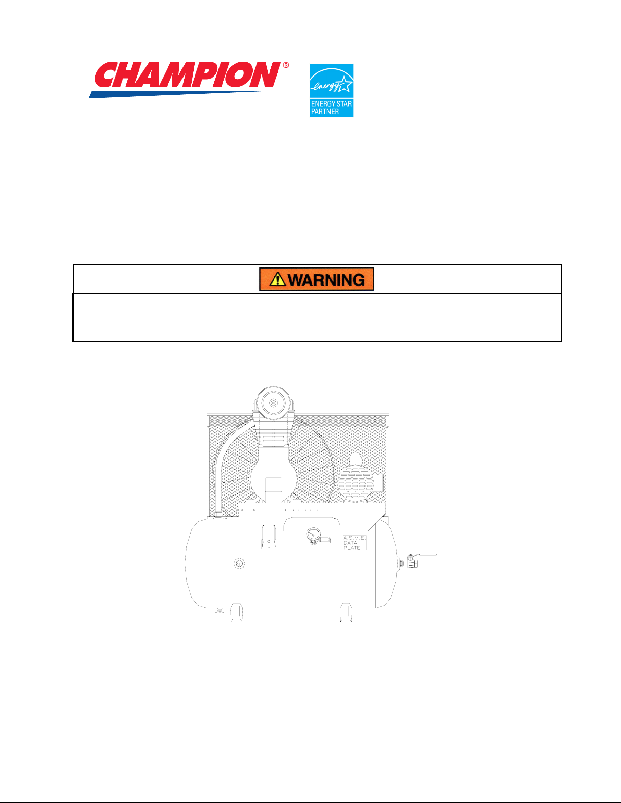
OPERATION MAINTENANCE
MANUAL & PARTS LIST
SINGLE STAGE ONE AND TWO CYLINDER OIL-LESS
AIR COMPRESSORS, 3/4 THROUGH 5 HP
THIS MANUAL CONTAINS IMPORTANT SAFETY INFORMATION AND SHOULD ALWAYS BE
AVAILABLE TO THOSE PERSONNEL OPERATING THIS UNIT.
READ, UNDERSTAND AND RETAIN ALL INSTRUCTIONS BEFORE OPERATING THIS
EQUIPMENT TO PREVENT INJURY OR EQUIPMENT DAMAGE.
Form No. F3266 VER: 12 07/01/2009
B998-A
(Ref. Drawing)
MODEL H3MTOIl - 6
Page 2

MAINTAIN COMPRESSOR RELIABILITY AND PERFORMANCE WITH
GENUINE CHAMPION
COMPRESSOR
PARTS AND SUPPORT SERVICES
Champion Compressor genuine parts, manufactured to design tolerances, are developed for optimum
dependability – specifically for Champion compressor systems. Design and material innovations are the result
of years of experience with hundreds of different compressor applications. Reliability in materials and quality
assurance are incorporated in our genuine replacement parts.
Your authorized Champion Compressor distributor offers all the backup you’ll need. A worldwide network of
authorized distributors provides the finest product support in the air compressor industry.
Your authorized distributor can support your Champion air compressor with these services:
1. Trained parts specialists to assist you in selecting the correct replacement parts.
2. Repair and maintenance kits designed with the necessary parts to simplify servicing your compressor.
Authorized distributor service technicians are factory trained and skilled in compressor maintenance and repair.
They are ready to respond and assist you by providing fast, expert maintenance and repair services.
For the location of your local authorized
Champion Air Compressor distributor, refer to the yellow
pages of your phone directory or contact:
Factory:
Champion
1301 North Euclid Avenue
Princeton, IL 61356
Phone: (815) 875-3321
Fax: (815) 872-0421
E-Mail: Champion@Champion pneumatic . com
INSTRUCTIONS FOR ORDERING REPAIR PARTS
When ordering parts, specify Compressor MODEL, HORSEPOWER and SERIAL NUMBER (see nameplate on
unit). All orders for Parts should be placed with the nearest authorized distributor.
Order by part number and description. Reference numbers are for your convenience only.
2
Page 3

TABLE OF CONTENTS
________________________________________________________
Subject Page
Maintain Compressor Reliability And Performance With .................................................. 2
Explanation Of Safety Instructions Symbols And Decals.................................................. 4
Safety And Operation Precautions.................................................................................... 5
Introduction........................................................................................................................ 6
Warranty ............................................................................................................................ 6
Specifications .................................................................................................................... 7
Installation ......................................................................................................................... 8
Operation................................................................................................................. 11 & 12
Maintenance......................................................................................................13, 14 & 15
Compressor Pilot Valve Differential Pressure Adjustment.............................................. 16
Parts Replacement Schedule..................................................................................17 & 18
Trouble Shooting Chart ...........................................................................................19 & 20
Unit Repair Parts List ..........................................................................................21 thru 26
Unit Hazard Decal Listing........................................................................................27 & 28
Pump Hazard Decals ...................................................................................................... 29
Record Of Maintenance Service .............................................................................30 & 31
3
Page 4
EXPLANATION OF SAFETY INSTRUCTIONS SYMBOLS AND DECALS
DANGER
Indicates immediate hazards which will result in severe injury or death.
WARNING
Indicates hazards or unsafe practice which could result in severe injury or death.
CAUTION
Indicates hazards or unsafe practice which could result in damage to the Champion
compressor or minor injury.
NOTICE
Notice is used to notify people of installation, operation or maintenance information which is
important but not hazard related.
SAFETY AND OPERATION PRECAUTIONS
OBSERVE, UNDERSTAND AND RETAIN THE INFORMATION GIVEN IN THE SAFETY
PRECAUTION DECALS AS SHOWN IN THE PARTS LIST SECTION.
DANGER
This Oil-Less Compressor must not be used for breathing air without adequate downstream
filters, purifiers and controls. To do so will cause serious injury whether air is supplied direct
from the compressor source or to breathing tanks for later use. Any and all liabilities for
damage or loss due to injuries, death and/or property damage including consequential
damages stemming from the use of this compressor to supply breathing air will be disclaimed
by the manufacturer.
WARNING
The use of this compressor as a booster pump and/or to compress a medium other than
atmospheric air is strictly non-approved and can result in equipment damage and/or injury.
Nonapproved uses will also void warranty.
CAUTION
This unit may be equipped with special options which may not be included in this manual. User
must read, understand and retain all information sent with special options.
4
Page 5

SAFETY AND OPERATION PRECAUTIONS
___________________________________________________________________________________
Because an air compressor is a piece of machinery with moving and rotating parts, the same precautions
should be observed as with any piece of machinery of this type where carelessness in operation or
maintenance is hazardous to personnel. In addition to the many obvious safety rules that should be
followed with this type of machinery, the additional safety precautions as listed below must be observed:
1. Read all instructions completely before operating air compressor or unit.
2. For installation, follow all local electrical and safety codes, as well as the National Electrical Code
(NEC) and the Occupational Safety and Health Act (OSHA).
3. Electric motors must be securely and adequately grounded. This can be accomplished by wiring
with a grounded, metal-clad raceway system to the starter; by using a separate ground wire
connected to the bare metal of the motor frame; or other suitable means.
4. Protect the power cable from coming in contact with sharp objects. Do not kink power cable and
never allow the cable to come in contact with oil, grease, hot surfaces, or chemicals.
5. Make certain that the power source conforms to the requirements of your equipment.
6. Pull main electrical disconnect switch and disconnect any separate control lines, if used, before
attempting to work or perform maintenance on the air compressor or unit. "Tag Out" or "Lock Out"
all power sources.
7. Do not attempt to remove any compressor parts without first relieving the entire system of
pressure.
8. Do not attempt to service any part while machine is in an operational mode.
9. Do not operate the compressor at pressures in excess of its rating.
10. Do not operate compressor at speeds in excess of its rating.
11. Periodically check all safety devices for proper operation. Do not change pressure setting or
restrict operation in any way.
12. Be sure no tools or rags or loose parts are left on the compressor or drive parts.
13. Do not use flammable solvents for cleaning the air inlet filter or element and other parts.
14. Exercise cleanliness during maintenance and when making repairs. Keep dirt away from parts by
covering parts and exposed openings with clean cloth or Kraft paper.
15. Do not operate the compressor without guards, shields and screens in place.
16. Do not install a shut-off valve in the discharge line, unless a pressure relief valve, of proper design
and size, is installed in the line between the compressor unit and shut-off valve.
17. Do not operate compressor in areas where there is a possibility of ingesting flammable or toxic
fumes.
18. Be careful when touching the exterior of a recently run motor - it may be hot enough to be painful
or cause injury. With modern motors this condition is normal if operated at rated load - modern
motors are built to operate at higher temperatures.
19. Inspect unit daily to observe and correct any unsafe operating conditions found.
20. Do not "play around" with compressed air, nor direct air stream at body, because this can cause
injuries.
21. Compressed air from this machine absolutely must not be used for food processing or breathing
air without adequate downstream filters, purifiers and controls.
22. Always use an air pressure regulating device at the point of use, and do not use air pressure
greater than marked maximum pressure of attachment.
23. Check hoses for weak or worn condition before each use and make certain that all connections
are secure.
24. Always wear safety glasses when using a compressed air blowgun.
The user of any air compressor package manufactured by Champion is hereby warned that failure to
follow the preceding Safety and Operation Precautions can result in injuries or equipment damage.
However, Champion does not state as fact or does not mean to imply that the preceding list of Safety and
Operating Precautions is all inclusive, and further that the observance of this list will prevent all injuries or
equipment damage.
5
Page 6

INTRODUCTION
Champion Oil-Less compressors are the result of advanced engineering and skilled manufacturing. To
be assured of receiving maximum service from this machine the owner must exercise care in its operation
and maintenance. This book is written to give the operator and maintenance department essential
information for day-to-day operation, maintenance and adjustment. Careful adherence to these
instructions will result in economical operation and minimum downtime.
Express Limited Warranty
CHAMPION warrants each new piece of equipment manufactured by CHAMPION to be free from
defects in material and workmanship under normal use and service for a period of twelve (12) months
from date of installation or eighteen (18) months from date of shipment by CHAMPION or CHAMPION
authorized distributor, whichever may occur first.
CHAMPION makes no warranty in respect to components and accessories furnished to CHAMPION by
third parties, such as ELECTRIC MOTORS, and CONTROLS, which are warranted only to the extent of
the original manufacturer's warranty to CHAMPION. To have warranty consideration, electric motors
must be equipped with thermal overload protection.
When a compressor pump, or component is changed or replaced during the warranty period, the newly
replaced item is warranted for only the remainder of the original warranty period.
Repair, replacement or refund in the manner and within the time provided shall constitute CHAMPION'S
sole liability and your exclusive remedy resulting from any nonconformity or defect. CHAMPION SHALL
NOT IN ANY EVENT BE LIABLE FOR ANY DAMAGES, WHETHER BASED ON CONTRACT,
WARRANTY, NEGLIGENCE, STRICT LIABILITY OR OTHERWISE, INCLUDING WITHOUT
LIMITATION ANY CONSEQUENTIAL, INCIDENTAL OR SPECIAL DAMAGES, ARISING WITH
RESPECT TO THE EQUIPMENT OR ITS FAILURE TO OPERATE EVEN IF CHAMPION HAS BEEN
ADVISED OF THE POSSIBILITY THEREOF.
CHAMPION MAKES NO OTHER WARRANTY OR REPRESENTATION OF ANY KIND, EXCEPT THAT
OF TITLE, AND ALL OTHER WARRANTIES, EXPRESS OR IMPLIED, INCLUDING WARRANTIES OF
MERCHANTABILITY AND FITNESS FOR A PARTICULAR PURPOSE, ARE HEREBY EXPRESSLY
DISCLAIMED. NO SALESMAN OR OTHER REPRESENTATIVE OF CHAMPION HAS AUTHORITY TO
MAKE ANY WARRANTIES.
6
Page 7
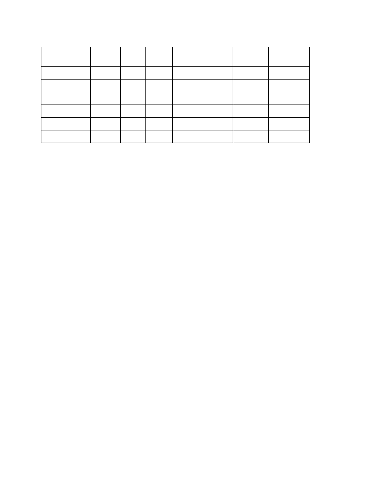
COMPRESSOR UNIT SPECIFICATIONS
COMPRESSOR
MODEL
CCE10 3/4 430 3.7 100 450 2100
CCE10 1 575 4.9 100 600 2800
CCE20 1½ 570 9.6 100 1315 3360
CCE20 2 680 11.5 100 1570 4480
CCE30 3 650 17.1 100 1500 6700
CVE50 5 650 27.4 100 1500 12,000
MOTOR
H.P.
PUMP
RPM
DISPL
(CFM)
MAXIMUM
PRESSURE (PSIG)
Minimum Ambient Temperature 32°F
Maximum Ambient Temperature 100°F
COOLING
AIR FLOW
(CFM)
HEAT
REJECTION
(BTU/HR)
7
Page 8
INSTALLATION
WARNING
Do not operate unit if damaged during shipping, handling or use. Operating unit if damaged
may result in injury.
1. Permanently installed compressors must be located in a clean, well ventilated dry room so
compressor receives adequate supply of fresh, clean, cool and dry air. It is recommended that a
compressor, used for painting, be located in a separate room from that area wherein body sanding
and painting is done. Abrasive particles or paint found to have clogged the air intake filters and
intake valves shall automatically void warranty.
2. Compressors should never be located so close to a wall or other obstruction that flow of air through
the cooling fan, which cools the compressor, is impeded. Permanently mounted units should have
cooling fan at least 12" from wall.
3. Place stationary compressors on firm level ground or flooring. Permanent installations require
bolting to floor. Bolt holes in tank or base feet are provided. Before bolting or lagging down, shim
compressor level to avoid putting a stress on a tank foot. It is recommended that unit be set on
optional vibro-isolator pads. Tanks bolted directly to a concrete floor without isolators will not be
warranted against cracking.
4. If installing a base mounted unit, make certain pressure limiting controls are properly installed and
operational. A pressure switch is required for start/stop control. Units furnished with dual control
are supplied with a pilot valve. The pilot valve requires a control air pressure line from the air
receiver to be connected to the pilot valve.
DANGER
Do not install isolating valves between compressor outlet and air receiver. This will cause
excessive pressure if valve is closed and cause injury and equipment damage.
DANGER
Factory assembled medical units equipped with an isolation valve have a pressure relief valve
installed in the discharge line between the compressor and isolation valve. Do not remove or
adjust.
WARNING
Always use an air pressure regulating device at the point of use. Failure to do so can result in
injury or equipment damage.
CAUTION
• Do not install an area where ambient temperature is below 32 degrees F. or above
100 degrees F.
• Do not install unit in an area where air is dirty and/or chemical laden.
• Unit is not to be installed outdoors.
8
Page 9
INSTALLATION (CONT’D)
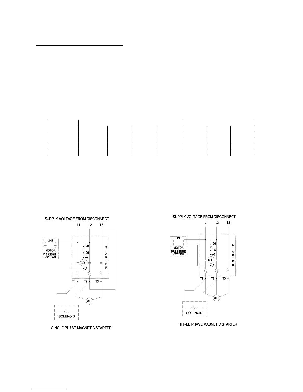
ELECTRICAL POWER SUPPLY
It is essential that the power supply and the supply wiring are adequately sized and that the voltage
corresponds to the unit specifications. Branch circuit protection must be provided at installation as
specified in the National Electrical Code.
All wiring should be performed by a licensed electrician or electrical contractor. Wiring must meet
applicable codes for area of installation. The table gives recommended wire sizes based on the
1999 NEC.
WIRE SIZE (AWG)
COPPER CONDUCTOR - 75°C TEMP. RATING - 30° AMBIENT
MOTOR
HP
200/208V 230V 460V 575V 115V 208V 230V
3/4 – 1-1/2 14 (14) 14 (14) 14 (14) 14 (14) 10 ( 8) 14 (10) 14 (12)
2 14 (12) 14 (12) 14 (14) 14 (14) 8 ( 6) 12 ( 8) 12 (10)
3 14 (10) 14 (12) 14 (14) 14 (14) 8 ( 4) 10 ( 8) 10 ( 8)
5 10 ( 8) 12 ( 8) 14 (12) 14 (12) ----- 8 ( 6) 8 ( 6)
Valves in ( ) for duplex unit with one incoming power line to both motors.
All models require a properly sized magnetic starter as specified in the National Electric Code (NEC).
See Figure 1-1 for simplex wiring diagram and Figure 1-2 for duplex wiring diagram.
If ordered with a factory mounted magnetic starter, compressor is wired at factory. It is necessary only to
bring lines from a properly sized disconnect switch to the magnetic starter mounted on the unit.
3 PHASE 1 PHASE
300CHS546-A
(Ref. Drawing)
Figure 1-1 Simplex Wiring Diagram
9
301CHS546-A
(Ref. Drawing)
Page 10
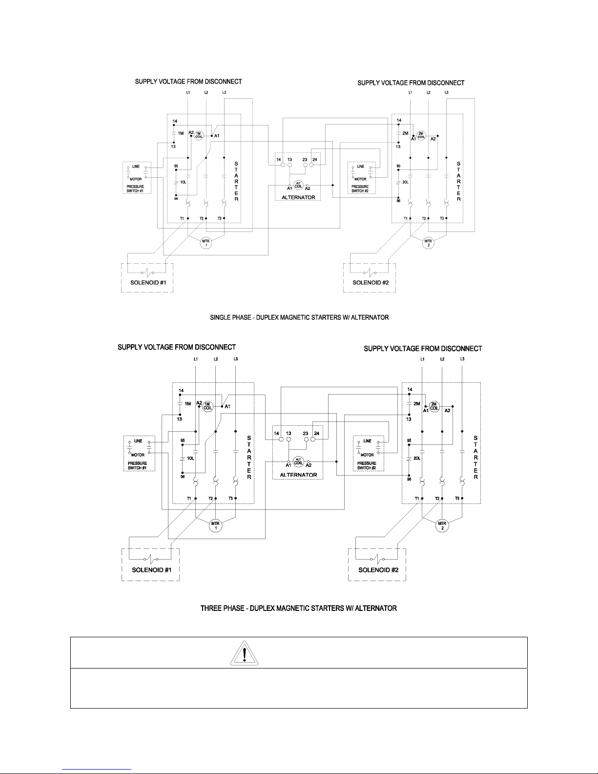
INSTALLATION (CONT’D)
300CHD546-A
(Ref. Drawing)
Wiring must be such that when viewing compressor from opposite shaft end, rotation of shaft is
clockwise as shown by arrow on guard. Wrong direction rotation for any length of time will
result in damage to compressor
Figure 1-2 Duplex Wiring Diagram
CAUTION
10
301CHD546-A
(Ref. Drawing)
Page 11

INSTALLATION (CONT’D)
GROUNDING INSTRUCTIONS
This product should be connected to a grounded, metallic, permanent wiring system, or an
AIR LINE PIPING
equipment-grounding terminal or lead on the product.
Connection to air system should be of the same size, or larger, than discharge pipe out of unit. The table
gives recommended minimum pipe sizes. A union connection to the unit and water drop leg is
recommended. Install a flexible connector between the discharge of the unit and the plant air piping. Plant
air piping should be periodically inspected for leaks using a soap and water solution for detection on all pipe
joints. Air leaks waste energy and are expensive
.
Minimum Pipe Sizes For Compressor Air Lines
(Based on clean Smooth Schedule 40 Pipe)
COMPRESSOR
MODEL
25’ 50’ 100’ 200’ 300’
CCE10 3/4” (1”) 3/4” (1”) 3/4” (1”) 3/4” (1”) 3/4” (1”)
CCE20 3/4” (1”) 3/4” (1”) 3/4” (1”) 3/4” (1”) 3/4” (1”)
CCE30 3/4” (1”) 3/4” (1”) 3/4” (1”) 3/4” (1”) 3/4” (1”)
CVE50 3/4” (1”) 3/4” (1”) 3/4” (1”) 1” (1-1/4”) 1” (1-1/4”)
Values in ( ) are for duplex unit.
WARNING
Never use plastic pipe or improperly rated metal pipe. Improper piping material can burst and
cause injury or property damage.
OPERATION
This compressor has been inspected, thoroughly tested and approved at the factory. For this unit to give long
satisfactory service it must be installed and operated properly.
This compressor has been designed to run at a 100% duty cycle.
Simplex units have a pressure switch that senses changes in receiver pressure and automatically starts and stops
the compressor at preset pressure limits. If the receiver pressure falls below the cut-in pressure setting of the
pressure switch the compressor will run until the cut-out pressure setting of the pressure switch has been reached.
Duplex units have lead and lag pressure switches and an automatic alternating system to evenly distribute the load
between the two compressors. The pressure switches sense changes in receiver pressure and automatically start
and stop the compressor at preset pressure levels. If the receiver pressure falls below the cut-in pressure setting of
the lead pressure switch but remains above the cut-in pressure setting of the lag pressure switch, only one
compressor will run until receiver pressure reaches the cut-out pressure of the lead pressure switch. The next time
the pressure in the receiver drops, the system automatically starts the compressor that was idle. If the receiver
pressure falls below the cut-in pressure setting of the lag pressure switch, both compressors run until receiver
pressure reaches the cut-out pressure setting of the lead pressure switch.
Units furnished with optional dual control are equipped with a needle valve, pilot valve and head unloaders to provide
continuous run capabilities. The pilot valve acts as an automatic air switch allowing air to flow from the receiver to the
head unloader mechanism, thus actuating it. To operate unit in continuous run, open needle valve located next to
pilot valve. The pilot valve is now able to sense receiver pressure. When the receiver pressure reaches the cut-out
pressure setting of the pilot valve, the pilot valve opens and air is released to the unloader mechanism. The
compressor stops compressing air and runs unloaded until the cut-in pressure setting of the pilot valve has been
reached. At this time air released from the unloader mechanism and the compressor starts compressing again.
Continuous run is recommended if motor starts exceed 8 starts/hour.
11
Page 12

OPERATION (CONT’D)
Initial Start Up
1. Inspect unit for any visible signs of damage that would have occurred in shipment or during
installation.
2. Pull main disconnect switch to unit to assure that no power is coming into the unit. “Lock Out” or “Tag
Out” switch. Connect power leads to starter.
WARNING
Do not attempt to operate compressor on voltage other than that specified on order
or on compressor motor.
3. Activate main disconnect switch.
4. “Jog” motor and check for proper rotation by direction arrow. If rotation is wrong, reverse input
connections on the magnetic starter.
5. Close receiver outlet hand valve and start.
6. With receiver hand valve closed, let machine pump up to operating pressure. At this stage the
automatic controls will take over. Check for proper cycling operation.
7. Check for proper operation of any options. Refer to individual option instruction sheet.
8. Open receiver hand valve. The air compressor unit is now ready for use.
WARNING
This unit can start automatically without warning.
12
Page 13

GUIDE TO MAINTENANCE
For Service contact an authorized Champion distributor. All requests should include model number
and serial number. To obtain reliable and satisfactory service, this unit requires a consistent
preventive maintenance schedule. Maintenance schedule form is included to aid in keeping the
proper records.
WARNING
Before performing any maintenance function, switch main disconnect switch to "off" position
to assure no power is entering unit. "Lock Out" or "Tag Out" all sources of power. Be sure all
air pressure in unit is relieved. Failure to do this may result in injury or equipment damage.
DAILY MAINTENANCE
1. Drain moisture from tank by opening tank drain cock located in bottom of tank. Do not open drain
valve if tank pressure exceeds 25 PSIG.
2. Turn off compressor at the end of each day's operation. Turn off power supply at wall switch.
WEEKLY MAINTENANCE
1. Clean dust and foreign matter from cylinder, cylinder head, motor, fan blade, air lines, and tank.
2. Remove and clean intake air filters.
WARNING
Do not exceed 15 PSIG nozzle pressure when cleaning element parts with compressed air. Do
not direct compressed air against human skin. Serious injury could result. Never wash
elements in fuel oil, gasoline or flammable solvent.
3. Check V-belts for tightness. The V-belts must be tight enough to transmit the necessary power to
the compressor. Adjust the V-belts as follows:
Remove bolts and guard to access compressor drive.
Loosen mounting hardware, which secures motor to base. Slide motor within slots of baseplate to
desired position.
Apply pressure with finger to one belt at midpoint span. Tension is correct if top of belt aligns with
bottom of adjacent belt. Make further adjustments if necessary.
Check the alignment of pulleys. Adjust if necessary.
Tighten mounting hardware to secure motor on base.
Re-install guard and secure bolts.
WARNING
Never operate unit without belt guard in place. Removal will expose rotating parts which can
cause injury or equipment damage.
13
Page 14

EVERY 90 DAYS OR 500 HOURS MAINTENANCE
1. Check entire system for air leakage around fittings, connections, and gaskets, using soap solution
and brush.
2. Tighten nuts and cap screws as required.
3. Check and clean compressor valves as required. Replace when worn or damaged parts.
GENERAL MAINTENANCE NOTES
PRESSURE RELIEF VALVE: The pressure relief valve is an automatic pop valve. Each valve is properly
adjusted for the maximum pressure of the unit on which it is installed. If it should pop, it will be
necessary to drain all the air out of the tank in order to reseat properly, or drop pressure in line. Do
not readjust.
TANK DRAIN VALVE: Drain valve is located at bottom of tank. Open drain valve daily to drain
condensation. Do not open drain valve if tank pressure exceeds 25 psig. The automatic tank drain
equipped compressor requires draining manually once a week.
PRESSURE SWITCH: The pressure switch is automatic and will start compressor at the low pressure
and stop when the maximum pressure is reached. It is adjusted to start and stop compressor at the
proper pressure for the unit on which it is installed. Do not readjust.
COMPRESSOR VALVES (CCE10): Once per year or if compressor fails to pump air or seems slow in
filling up tank, disconnect unit from power source remove valve plate and clean thoroughly, using
compressed air. The valve plates can be reached by removing the cylinder head. The cylinder head
is held by four capscrews. After cleaning exceptional care must be taken that all parts are replaced
in exactly the same position and all joints must be tight or the compressor will not function properly.
When all valves are replaced and connections tight, close hand valve at tank outlet for final test.
COMPRESSOR VALVES (CCE20, CCE30, CVE50): Once per year or if compressor fails to pump air or
seems slow in filling up tank, disconnect unit from power source and remove valves and clean
thoroughly, using compressed air and a soft wire brush. The valve plates can be reached by
removing the cylinder head. Each cover is held by four capscrews. Take care not to damage the
“O”-Ring seal under the top of the cover. After cleaning exceptional care must be taken that all
parts are replaced in exactly the same position and all joints must be tight or the compressor will
not function properly. When all valves are replaced and connections tight, close hand valve at tank
outlet for final test.
Valves must be replaced in original position. Valve gaskets should be replaced each time
valves are serviced.
CHECK VALVE: The check valve closes when the compressor stops operating, preventing air from
flowing out of the tank through the unloader solenoid valve. After the compressor stops operating, if
air continues to escape through the unloader solenoid valve, it is an indication that the check valve is
leaking. This can be corrected by removing check valve and cleaning disc and seat. If check valve
disc is worn badly, replace same.
Before removing check valve be sure all air is drained out of tank and power is disconnected.
Failure to do so may result in injury or equipment damage.
CAUTION
WARNING
14
Page 15

GENERAL MAINTENANCE (Cont'd.)
BELTS: Drive belts must be kept tight enough to prevent slipping. If belts slip or squeak, see V-belt
maintenance in preceding section.
MOTOR LUBRICATION: Long time satisfactory operation of an electric motor depends in large measure
on proper lubrication of the bearings. Bearing grease will lose its lubricating ability overtime, not
suddenly. Refer to the motor manufacturer’s instructions for the type of grease and lubrication
intervals.
PILOT VALVE: (Optional - Dual Control Units Only) The pilot valve actuates the head unloader
mechanism to provide a means of stopping or starting the compression of air by the compressor
without stopping or starting the electric motor.
15
Page 16

COMPRESSOR PILOT VALVE PRESSURE ADJUSTMENT (DUAL CONTROL UNITS ONLY)
Proceed with the following instructions while compressor is running:
1. Loosen locknut (2) and back off several turns.
2. Check reading on the tank pressure gauge. Set the pressure to 30 psig differential (unload at 95
psig, reload at 65 psig). Turn nut (3) clockwise to increase differential pressure or counterclockwise
to decrease differential pressure.
3. After pressure is set, tighten locknut (2). Be careful not to move nut (3).
COMPRESSOR PILOT VALVE DIFFERENTIAL PRESSURE ADJUSTMENT
Proceed with the following instructions while compressor is running.:
1. Loosen locknut (2) and back off several turns.
2. Check reading on the tank pressure gauge. Set the pressure to 30 psig differential (unload at 95
psig, reload at 65 psig). Turn nut (3) clockwise to increase differential pressure or
counterclockwise to decrease differential pressure.
3. After pressure is set, tighten locknut (2). Be careful not to move nut (3).
16
B980-B
W
(Ref. Drawing)
Page 17

PARTS REPLACEMENT SCHEDULE
1. Replace compression rings every 3 years (2 years if 60 or more hours/week run time).
2. Replace control rings every 3 years (2 years if 60 or more hours/week run time).
3. Change both main shaft and con rod bearings every 4 years (3 years if 60 or more hours/week run
time).
4. Replace head valves or valve plates every 2 years (1 year if 60 or more hours/week run time).
PISTON RING REPLACEMENT
Piston rings can be inspected or replaced by doing the following:
1. Make sure all power is off to the unit and the air receiver is at 0 PSIG.
2. Loosen and remove the discharge line or manifold.
3. Loosen and remove the four capscrews holding the cylinder to the crankcase.
4. Pull the cylinder/head assembly straight off of the crankcase (Take care not to damage the
piston/con rod during this removal).
5. The piston and rings will then be exposed.
6. Inspect and replace the rings as required (Note that the CCE20, CCE30 and CVE50 compression
rings are of the two separate piece design and take care not to drop or break the overlap ends of the
ring).
7. Replace rings on piston and carefully slide cylinder over the piston until it sets on the crankcase.
8. Tighten four capscrews that hold the cylinder to the crankcase.
9. Reinstall the discharge line or manifold.
CCE10 CRANKSHAFT BEARING AND CON ROD REPLACEMENT
Crankshaft bearings can be replaced as follows:
1. Disconnect all power to the unit and bleed down the air receiver pressure to 0 PSIG.
2. Remove the belt guard and the V-belt.
3. Remove the flywheel.
4. Remove the cylinder from the crankcase.
5. Loosen the two setscrews in the pin boss area tightened against the pin on the inside area of the
piston.
6. Push the piston pin out to remove the piston from the top of the con rod.
7. Remove crankcase breather cover and foam material on the front end of the crankcase. This will
expose a round opening in the crankcase in line with the crankshaft end.
8. Remove snap ring on the rod of the crankshaft using snap ring pliers.
9. Remove the con rod assembly using a gear puller.
10. If only installing con rod assembly, heat the lower end bearing on a hot plate to 190°F. Using heat
resistant gloves, quickly slide bearing on the rod of the crankshaft to proper location and reinstall the
snap ring.
11. Remove the 2 capscrews located inside the crankcase on the flywheel end.
12. Remove the flywheel key located on the crankshaft outside the crankcase.
13. Carefully remove the crankshaft from the crankcase using a press.
14. Remove the first bearing (smaller) from the crankshaft using gear puller.
15. Remove snap ring on the crankshaft using snap ring pliers.
16. Remove the second bearing (larger) from the crankshaft using gear puller.
17. To install new crankshaft bearings on the shaft, heat bearings to 190°F. Using heat resistant gloves
quickly slide larger bearing to proper location on the crankshaft, reinstall snap ring, then slide smaller
bearing to proper location on the crankshaft.
18. Reassemble compressor by reversing procedures stated 1 through 13.
17
Page 18

CCE20, CCE30, & CVE50 CRANKSHAFT BEARING AND CON ROD
REPLACEMENT
Crankshaft bearings can be replaced as follows:
1. Disconnect all power to the unit and bleed down the air receiver pressure to 0 PSIG.
2. Remove the belt guard and the V-belts.
3. Remove the flywheel.
4. Remove the cylinder(s) from the crankcase.
5. Loosen the two setscrews in the pin boss area tightened against the pin on the inside area of the
piston(s).
6. Push the piston pin out to remove the piston from the top of the con rod.
7. Loosen and remove the bearing cover on the flywheel end. Jackscrews are provided to remove this
cover.
8. Remove the crankcase breather cover and foam material on the front end of the crankcase. This will
expose a slotted opening in the crankcase casting in line with the crankshaft end.
9. Using a drift and hammer, push the end of the crankshaft bearing toward the pulley end until the
front side crankshaft bearing is free from the crankcase.
10. Carefully remove the crankshaft/con rod assembly from the crankcase through the opening in the
flywheel end.
11. The crankshaft bearings can be removed from the crankcase with bearing puller.
12. If the connecting rods need to be removed from the crankshaft, jackscrews are provided in the
crankcase adjacent to the con rod bearing for this purpose (remove the snap ring before using the
jackscrews). To install a new con rod assembly, heat the lower end bearing on a hot plate to 190°F.
Using heat resistant gloves, quickly slide con rod on shaft, starting at flywheel end to its proper place
on the shaft throw.
13. To install a new con rod assembly, heat the lower end bearing on a hot plate to 190° F. Using heat
resistant gloves, quickly slide bearings on each end of shaft, starting at flywheel end to its proper
place on the shaft throw.
14. Reinstall snap ring.
15. To install new crankshaft bearings on shaft, heat bearings to 190°F. Using heat resistant gloves,
quickly slide bearings on each end of shaft, making sure the smaller bearing is installed on the front
end of the crankshaft.
16. Reassemble compressor by reversing procedures stated in 1 through 10.
18
Page 19

g
TROUBLE SHOOTING GUIDE FOR COMPRESSOR
WARNING
Always disconnect unit from power supply and relieve all pressure from air tank before
performing any maintenance. “Tag Out” or “Lock Out” disconnect switch. Failure to do so may
result in equipment damage or injury.
Never use gasoline or flammable solvent on or around compressor unit. Explosion may result.
Troubleshooting Chart
Symptom Possible Cause(s) Corrective Action
Motor will not start.
Starter trips repeatedly. 1. Improperly adjusted pressure switch.
Tank pressure builds up slowly. 1. Air leaks.
Tank pressure builds up quickly. 1. Excessive water in tank. 1. Drain tank.
Discharge pressure relief valve pops
off while compressor is running.
1. Main switch and fuses open.
2. Starter heater coils open.
3. Starter tripped
4. Defective pressure switch contacts will not close
5. Low voltage.
2. Faulty check valve.
3. Incorrect fuse size or magnetic starter
heaters.
4. Low voltage.
5. Defective motor.
2. Dirty air filter.
3. Defective compressor valves
1. Wrong pressure switch setting.
2. Defective ASME relief valve.
1. Check all fuses and switches. Check
for loose or faulty wires.
2. Check overload relay in starter.
Reset starter.
3. Reset starter. If starter trips
repeatedly, have electrical system
inspected by an electrician.
4. Repair or replace pressure switch.
Warning – Relieve tank pressure
before servicing.
5. Check with voltmeter. Be sure
voltage corresponds to unit
specifications.
1. Adjust or replace.
Warning – Relieve tank pressure
before servicing.
2. Clean or replace
Warning – Relieve tank pressure
before servicing.
3. Be sure that fuses and heaters are
properly rated.
4. Check with voltmeter. Be sure
voltage corresponds to unit
specifications.
5. Replace motor.
1. Tighten fittings.
2. Clean or replace.
3. Install new valves.
1. Adjust to correct setting.
2. Replace valve.
Compressor will not unload
(Dual control units only)
Excessive belt wear. 1. Pulley out of alignment.
Compressor runs hot. 1. Improper flywheel rotation
1. Wrong pilot valve setting.
2. Defective pilot valve.
3. Lack of air to pilot valve..
2. Belts too tight or too loose.
2. Defective compressor valves.
3. Dirty air filter.
4. Dirty cylinder and/or intercooler.
19
Warning – Relieve tank pressure
before servicin
1. Adjust to correct setting
2. Replace pilot valve.
3. Open needle valve to pilot valve.
1. Realign motor pulley.
2. Adjust belt tension.
1. Check for correct rotation.
(Counter clockwise when viewed
from drive side.
2. Install new valve plate assembly.
3. Clean or replace.
4. Clean cylinder fins and/or intercooler.
.
Page 20

Troubleshooting Chart (cont’d)
Symptom Possible Cause(s) Corrective Action
Air leaking from unloading solenoid
valve when unit is running.
System does not alternate
(Duplex units only)
1. Check valve stuck in open position.
2. Incorrect wiring of solenoid valve.
3. Defective solenoid valve.
1. Starter tripped.
2. Loose wiring in alternator.
3. Defective alternator.
4. Defective motor.
1. Replace check valve.
Warning – Relieve tank pressure
before servicing.
2. Check all wiring. Check for loose or
faulty wires. Check for correct
voltage.
3. Replace solenoid valve.
1. Reset starter. If starter trips
repeatedly, have electrical system
inspected by an electrician.
2. Check and tighten all wiring
connections.
3. Replace alternator.
4. Replace motor.
20
Page 21

B999-B
(Ref. Drawing)
REPAIR PARTS LIST
115V 200V 230V 460V
PART NO. PART NO. PART NO. PART NO.
Note: Common to all Units – Unloader Solenoid Valve
CC1019457 CC1019455 CC1019459 CC1019456
UNIT REPAIR PARTS ILLUSTRATION
MODELS: H.7MTOII-3, H.7MTOII-6, H1MTOII-3, H1MTOII-6, H1.5MTOII-3, H1.5MOTII-6, H2MTOII-3, H2MTOII-6, H3MTOII-6, & H5MTOII-6
1 Pump CCE10 CCE10 CCE10 CCE10 CCE20 CCE20 CCE20 CCE20 CCE30 CVE50
2 Motor 3/4 HP 3/4 HP 1 HP 1 HP 1.5 HP 1.5 HP 2 HP 2 HP 3 HP 5 HP
MODEL
H.7MTOII-3 H.7MTOII-6 H1MTOII-3 H1MTOII-6 H1.5MTOII-3 H1.5MTOII-6 H2MTOII-3 H2MTOII-6 H3MTOII-6 H5MTOII-6
3 Pulley 1 PHASE P09947A P09947A P09965A P09965A P12026A P12026A P12027A P12027A P11992A P11858C
21
3 Pulley 3 PHASE P09947A P09947A P09949A P09949A P12026A P12026A P11999A P11999A P11992A P11858C
4 Tank P11938D P11937D P11938D P11937D P11938D P11937D P11938D P11937D P11937D P11937D
5 Belts A61 (1) A61 (1) A61 (1) A61 (1) 4L510 (2) 4L510 (2) 4L510 (2) 4L510 (2) 4L510 (2) B48 (2)
6 Belt Guard Z12722 Z12722 Z12722 Z12722 Z9130 Z9130 Z9130 Z9130 Z9130 Z9132
7 Check Valve P05822A P05822A P05822A P05822A P05822A P05822A P05822A P05822A P05822A P05822A
8 Isolation Valve M3590 M3590 M3590 M3590 M3590 M3590 M3590 M3590 M3590 M3590
9 Drain Valve VP1022988 VP1022988 VP1022988 VP1022988 VP1022988 VP1022988 VP1022988 VP1022988 VP1022988 VP1022988
10 Pressure Switch P05007A P05007A P05007A P05007A P05007A P05007A P05007A P05007A P05007A P05007A
11 Pressure Gauge M519C M519C M519C M519C M519C M519C M519C M519C M519C M519C
12 Pressure Relief Valve M2843 M2843 M2843 M2843 M2843 M2843 M2843 M2843 M2843 M2843
13 Bucket High Drain Z1541 Z1541 Z1541 Z1541 Z1541 Z1541 Z1541 Z1541 Z1541 Z1541
Page 22

UNIT REPAIR PARTS ILLUSTRATION
MODELS: B.7MTOII B1MTOII, B1.5MTOII, B2MTOII, B3MTOII, & B5MTOII
C383-A
(Ref. Drawing)
REPAIR PARTS LIST
B.7MTOII B1MTOII B1.5MTOII B2MTOII B3MTOII B5MTOII
1 Pump CCE10 CCE10 CCE20 CCE20 CCE30 CVE50
2 Belt Guard Z12722 Z12722 Z9130 Z9130 Z9130 Z9132
3 Base Plate P11933C P11933C P11933C P11933C P11933C P11933C
4 Motor 3/4 HP 1 HP 1.5 HP 2 HP 3 HP 5 HP
5 Pulley
5 Pulley
6 Belts A61 (1) A61 (1) A61 (1) 4L510 (2) 4L510 (2) B48 (2)
1 PHASE
3 PHASE
P09947A P09965A P12026A P12027A P11992A P11858C
P09947A P09949A P12026A P11999A P11992A P11858C
MODEL
Note: Common to all Units – Unloader Solenoid Valve
115V 200V 230V 460V
PART NO. PART NO. PART NO. PART NO.
CC1019457 CC1019455 CC1019459 CC1019456
22
Page 23

C384-A
(Ref. Drawing)
MODEL
REPAIR PARTS LIST
115V 200V 230V 460V
Note: Common to all Units – Unloader Solenoid Valve
PART NO. PART NO. PART NO. PART NO.
CC1019457 CC1019455 CC1019459 CC1019456
H3MTOIID-8, H3MTOIID-12, H5MTOIID-8, & H5MTOIID-12
UNIT REPAIR ILLUSTRATION
MODEL: H.7HTOIID-6, H.7MTOIID-8, H1MTOIID-6, H1MTOIID-8, H1.5MTOIID-6, H1.5MTOIID-6, H2MTOIID-6, H2MTOIID-8,
23
M2843 M2843 M2843 M2843 M2843 M2843 M2843 M2843 M2843 M2843 M2843 M2843
Pressure Relief
H.7MTOIID-6 H.7MTOIID-8 H1MTOIID-6 H1MTOIID-8 H1.5MTOIID-6 H1.5MTOIID-8 H2MTOIID-6 H2MTOIID-8 H3MTOIID-8 H3MTOIID-12 H5MTOIID-8 H5MTOIID-12
1 Pump CCE10 CCE10 CCE10 CCE10 CCE20 CCE20 CCE20 CCE20 CCE30 CCE30 CVE50 CVE50
2 Pressure Gauge M519C M519C M519C M519C M519C M519C M519C M519C M519C M519C M519C M519C
3 Belt Guard Z12722 Z12722 Z12722 Z12722 Z9130 Z9130 Z9130 Z9130 Z9130 Z9130 Z9132 Z9132
4 Belt Guard Z12723 Z12723 Z12723 Z12723 Z9131 Z9131 Z9131 Z9131 Z9131 Z9131 Z9133 Z9133
5 Drain Valve VP1022988 VP1022988 VP1022988 VP1022988 VP1022988 VP1022988 VP1022988 VP1022988 VP1022988 VP1022988 VP1022988 VP1022988
6 Check Valve P05822A P05822A P05822A P05822A P05822A P05822A P05822A P05822A P05822A P05822A P05822A P05822A
7 Bucket High Drain Z1541 Z1541 Z1541 Z1541 Z1541 Z1541 Z1541 Z1541 Z1541 Z1541 Z1541 Z1541
8 Pressure Switch P05007A P05007A P05007A P05007A P05007A P05007A P05007A P05007A P05007A P05007A P05007A P05007A
9
Valve
10 Motor 3/4 HP 3/4 HP 1 HP 1 HP 1.5 HP 1.5 HP 2 HP 2 HP 3 HP 3 HP 5 HP 5 HP
11 Tank P11936D P11934D P11936D P11934D P11936D P11934D P11936D P11934D P11934D P11935D P11934D P11935D
12 Isolation Valve CQM3756 CQM3756 CQM3756 CQM3756 CQM3756 CQM3756 CQM3756 CQM3756 CQM3756 CQM3756 CQM3756 CQM3756
13 Pulley 1 PHASE P09947A (2) P09947A (2) P09965A (2) P09965A (2) P12026A (2) P12026A (2) P12027A (2) P12027A (2) P11992A (2) P11992A (2) P11858C (2) P11858C (2)
13 Pulley 3 PHASE P09947A (2) P09947A (2) P09949A (2) P09949A (2) P12026A (2) P12026A (2) P11999A (2) P11999A (2) P11992A (2) P11992A (2) P11858C (2) P11858C (2)
14 Belts A61 (2) A61 (2) A61 (2) A61 (2) 4L510 (4) 4L510 (4) 4L510 (4) 4L510 (4) 4L510 (4) 4L510 (4) B48 (4) B48 (4)
Page 24

COMPRESSOR REPAIR PARTS ILLUSTRATION
MODEL: CCE10
1
13
2
16
11
10
15
17
3
C351-B
(Ref. Drawing)
4
6
Repair Parts List
Model CCE10
Ref. No. Description Part Number Qty.
1 Cylinder Head P14341A 1
2 Inlet/Outlet Valve Assembly P14350A 2
3 Shaft Bearing-Front End P14347A 1
4 Shaft Bearing-Flywheel End P14346A 1
5 Seal, Piston Pin P14345A 2
6 Connecting Rod and Bearing P14351A 1
7 Crankcase Breather P14349A 1
8 Piston Pin P14348A 1
9 Piston P14342A 1
10 Control Ring P14344A 1
11 Compression Ring P14343A 2
12 Piston Ring Set Z12418 1
13 Intake Filter Element P09974A 1
14 Snap Ring, 37MM P14355A 1
15 Snap Ring, 32MM P14356A 1
16 Cylinder P14357A 1
17 Flywheel P14358A 1
Note: For All Other Parts, Contact Factory Service Dept.
12
9
8
5
7
14
24
Page 25

COMPRESSOR REPAIR PARTS ILLUSTRATION
MODELS: CCE20 & CCE30
B1000-E
(Ref. Drawing)
Repair Parts List
Models: CCE20, CCE30
Ref. No. Description Part No. Qty. Part No. Qty.
1 Intake Valve P11860A 1 P11867A 1
2 Exhaust Valve P11861A 1 P11868A 1
3 “O”Ring Seal-Valve Cover P11862A 2 P11869A 2
4 Exhaust Valve Gasket P12770A 1 P12771A 1
5 Cylinder Head P12768A 1 P12769A 1
6 Piston P12772A 1 P12773A 1
7 Compression Ring P11859A 2 P11866A 2
8 Control Ring P12774A 2 P12775A 2
9 Piston Ring Set Z9495 1 Z9496 1
10 Piston Pin Seal P12778A 2 P12778A 2
11 Cylinder Gasket P12776A 1 P12777A 1
12 Intake Filter Element P05050A 1 P05050A 1
13 Shaft Bearing-Front End P12829A 1 P12829A 1
14 Shaft Bearing-Flywheel End P12827A 1 P12827A 1
15 Cover Gasket P12825A 1 P12825A 1
16 Connecting Rod and Bearing Z9503 1 Z9503 1
17 Piston Pin P12824A 1 P12826A 1
18 Crankcase Breather P13437A 1 P13437A 1
19 Piston, Unloader, MT0II, CE30
(Included on Head Unloader Pumps Only)
20 Cylinder CC1009504 1 CC1009505 1
21 Pulley CC1011356 1 CC1011356 1
22 Flywheel CC1011357 1 CC1011357 1
23 Pin, Crankshaft CC1011358 1 CC1011358 1
24 Fasteners, Flywheel CC1011359 1 CC1011359 1
25 Valve Clamp, Inlet CC1035092 1 CC1035093 1
26 Valve Clamp, Outlet CC1035094 1 CC1035097 1
CCE20 Qty. CCE30
CQP14901A 1 CQP14862A 1
Note: For All Other Parts, Contact Factory Service Dept.
25
Page 26

COMPRESSOR REPAIR PARTS ILLUSTRATION
MODEL: CVE50
21
Repair Parts List
Model CVE50
Ref. No. Description Part Number Qty.
1 Intake Valve P11860A 2
2 Exhaust Valve P11861A 2
3 “O”Ring Seal-Valve Cover P11862A 4
4 Exhaust Valve Gasket P12770A 2
5 Cylinder Head P12768A 2
6 Piston P12772A 2
7 Compression Ring P11859A 4
8 Control Ring P12774A 4
9 Piston Ring Set Z9495 2
10 Piston Pin Seal P12778A 4
11 Cylinder Gasket P12776A 2
12 Intake Filter Element P05050A 1
13 Shaft Bearing-Front End P12830A 1
14 Shaft Bearing-Flywheel End P12828A 1
15 Cover Gasket P12825A 1
16 Connecting Rod and Bearing Z9504 2
17 Piston Pin P12824A 2
18 Crankcase Breather P13437A 1
19 Intercooler Tube P14366A 1
20 Piston, Unloader, MT0II, VE50
(Included on Head Unloader Pumps Only)
21 Cylinder CC1009506 2
22 Pin, Crankshaft CC1011358 1
23 Fasteners, Flywheel CC1011359 1
24 Flywheel CC1011357 1
25 Valve Clamp, Inlet CC1035096 2
26 Valve Clamp, Outlet CC1035095 2
CQP14896A 2
Note: For All Other Parts, Contact Factory Service Dept.
B1001-F
(Ref. Drawing)
26
Page 27

UNIT HAZARD DECAL LISTING
PAGE DESCRIPTION PART NO.
28 PRODUCT LIABILITY DECAL SHEET - MASTER P10157A
Unit Pressure Setting 1
NOT USED 2
DANGER – Breathing Air 3
DANGER – Drain Tank Daily 4
WARNING – Pressure/Safety Valve 5
NOT USED 6
DANGER – Valve Maintenance 7
DANGER – High Voltage 8
WARNING – Hot Surfaces 9
WARNING – Do Not Remove Fan Guard 10
NOT USED 11a
NOT USED 11b
NOT USED 12
NOT USED 13
DECAL – Pressure Setting: 70-100 PSIG 14
NOTICE – Read and Retain Manuals 15
INSTRUCTIONS – Dual Control (Optional) 16
DECAL – Rotation Direction 17
NOT USED 18
DECAL – Pressure Switch P14677A
PUMP HAZARD DECAL LISTING
PAGE DESCRIPTION PART NO.
29 PUMP DECAL SHEET – MASTER P13805A
NOT USED
NOT USED
DECAL – Rotation Direction
NOTICE – Read and Retain Manuals
DANGER – Breathing Air
DECAL – Made in the United States of America
IMPORTANT NOTICE – Motor Burn-outs
A1
A2
B
C
D
E
F
P14677A
27
Page 28

UNIT HAZARD DECALS
28
Page 29

PUMP HAZARD DECALS
F
29
Page 30

RECORD OF MAINTENANCE SERVICE
Daily
• DRAIN MOISTURE FROM TANK
WEEKLY
• CLEAN FILTER
• CLEAN COMPRESSOR
• CHECK V-BELTS
EVERY 3 MONTHS
• INSPECT VALVE ASSEMBLIES
•TIGHTEN ALL FASTENERS
•TEST PRESSURE RELIEF VALVE
30
Page 31

RECORD OF MAINTENANCE SERVICE
Daily
• DRAIN MOISTURE FROM TANK
WEEKLY
• CLEAN FILTER
• CLEAN COMPRESSOR
• CHECK V-BELTS
EVERY 3 MONTHS
• INSPECT VALVE ASSEMBLIES
•TIGHTEN ALL FASTENERS
•TEST PRESSURE RELIEF VALVE
31
Page 32

*F3266VER12*
*F3266VER12*
Copyright © 2009 Gardner Denver, Inc.
Printed in U.S.A.
www.championpneumatic.com
Champion
1301 North Euclid Avenue
Princeton, Illinois 61356 USA
Phone (815) 875-3321
Fax (815) 872-0421
E-mail: champion@championpneumatic.com
Plants in Princeton, IL, and Manteca, CA
Due to Champion’s continuing product development program,
specifications and materials are subject to change without notice or
obligation
 Loading...