

Page 1

C44F
C44F
E
E
LLIPTICAL
LLIPTICAL
T
T
RAINER
RAINER
Champion and C logo are used under li cense from Champion Ath leticwear
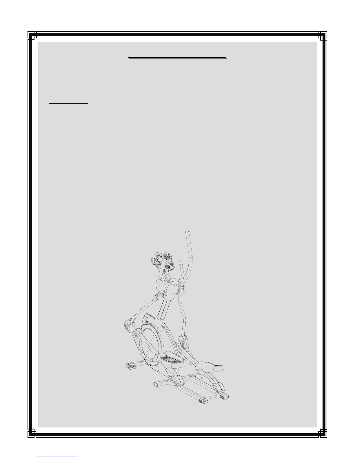
A
SSEMBLY
A
SSEMBLY
MPORTANT
I
MPORTANT
I
MPORTANT
I
SAFETY GUIDELINES AND WARNING LABELS. RETAIN PRODUCT LITERATURE FOR FUTURE REFERENCE.
SS
EXERCISING , STOP IMMEDIATELY AND CONSULT YOUR PHYSICIAN.
SERIAL NO. __________________________________________ PURCHASE DATE:_______________________
Part No. 06055 Revision: A Date: 09/05
:
READ ALL ASSEMBLY INSTRUCTIONS AND SAFETY PRECAUTIONS BEFORE USING THIS PRODUCT. REFERENCE ALL
:
:
AFETY
: PROPERLY WARM UP AND STRETCH BEFORE EXERCISING. IF YOU FEEL PAIN OR DIZZINESS AT ANY TIME WHILE
AFETY
I
NSTRUCTIONS
I
NSTRUCTIONS
/ O
/ O
WNERS
WNERS
M
ANUAL
M
ANUAL
Page 2

PAGE 1 TABLE OF CONTENTS
C44F
Reference Information Page
Assembly Prep & Intro 2
Parts Listing 3
Hardware Chart 4
Product Exploded View 5
Product Assembly Instruction 6-13
Computer Operation 14-18
Troubleshooting 19
Preventative Maintenance 20
Warranty Terms 21
Product Registration 22
I
MPORTANT
I
MPORTANT
WARNING: To reduce the risk of injury, please read the following precautions before assembling or using this product.
1. It is the responsibility of the owner to ensure that all users of this equipment are adequately informed of stated precautions.
2. Read all instructions and enclosed literature carefully. Understand the assembly and operation before using the equipment.
3. Use equipment on a flat level surface. Use adjustment levelers on the bottom of equipment to help stabilize unit.
4. It’s recommended to place an exercise / product mat beneath the equipment for added protection of floors or carpets.
5. Keep children & pets away from equipment at all times. Unplug equipment for added safety while not in use.
6. Inspect product on a frequent basis. Tighten lose assemblies or hardware as needed. Replace worn or damaged parts.
7. This equipment is intended for internal home use only. Do not use in a non-residential environment.
Use in non- recommended environments can lead to serious injury and will void all related warranties & liabilities.
8. Recommended user weight should not exceed 300 lbs.
9. Frequently wipe equipment down with a dampened soft cloth.
10. Observe and adhere to all warning labels posted on equipment.
11. Properly warm-up and stretch before starting any strength training or cardio exercise routine.
P
RECAUTIONS
P
RECAUTIONS
12. If you feel pain or dizziness at any time while exercising, stop immediately and consult your physician.
Safety Warning: Before starting an exercise program, consult your physician. This is especially important for individuals over the
age of 35 or persons with pre-existing health problems. It’s important to read all instructions carefully. We assume no responsibility for personal injury or consequential damages sustained by or through the use of this equipment. Additional terms & conditions are listed in the back of this manual or enclosed owners manual.
Page 3
PAGE 2 ASSEMBLY PREP & INTRO.
A
SSEMBLY
A
SSEMBLY
♦ The product assembly process has been documented in easy to follow stages. Please read all assembly
instructions carefully. Take time to review the manual and familiarize yourself with the entire
assembly process before proceeding.
Assembly Tip: It is always helpful to pre-stage the items needed for each assembly step.
♦ To ensure ease of product assembly, please take time to verify the size and quantities of all required
assembly hardware. Use the itemized parts listing as reference.
♦ Perform product assembly in a 4ft. x 6ft. flat area. Note: After assembly is completed, allow a minimal
of 2-3ft. of space on each side of unit for user access and dismounting.
♦ The basic tools for assembling this product are included with main assembly hardware.
♦ Do not dispose of any packaging materials until assembly of the product is completed.
♦ If you experience problems with operation of the equipment after assembly, please review the
troubleshooting reference page in this manual.
♦ Fill-out the product registration form and return it to us within 30-days of purchase.
♦ For added component life, follow the preventative maintenance tips listed in this manual.
♦ Please contact us if have additional questions or need service assistance.
P
REPARATION
P
REPARATION
C
USTOMER
C
USTOMER
S
ERVICE
S
ERVICE
1-877-861-2181
Page 4

PAGE 3
PARTS REFERENCE
C44F PP
ARTS
ARTS
Item Part Description QTY.
1 23110 Fr o n t S t a bi l i z e r A s s e mb l y 1
2 NA Base Assembly 1
3 12059 Lower Data Cable 1
4 05183 Stabilizer Extension Assembly 2
5 23107 Ha n d l e b a r Ma s t A s s e mb l y 1
6 11025 Up p e r D a t a Ca b l e 1
7 07125 Shroud Boot 1
8 13107 Pi v o t Ar m A s s e m bl y ( L e ft) 1
9 13108 P i v o t A rm A s s e m b ly ( R i g h t ) 1
10 23114 P e d al A r m A s s e mb l y ( L e ft) 1
11 23115 Pe d a l A r m A s s e m b l y ( R ig h t ) 1
12 23140 Co m p u t e r M ou n t i n g B r a c ke t 1
L
L
Item Part Description QTY.
29 07116 (P r e i n s t al l e d ) R o l l e r C o v e r ( R i g h t) 2
30 10027 Computer 1
31 14001 AC Adapter 1
32 31001 Bottle Cage 1
33 31010 Sports Bottle 1
34 01003 Bu t t o n H e ad A l l e n B o l t M8 x 1 . 2 5 x 1 6 L en g t h 2
35 01385 Fl a t W a s he r 8 x 1 9 x 2t 2
36 01015 Acorn Nut M8 4
37 01372 He x B o l t M 8 x 1 . 2 5 x 5 0 L en g t h 4
38 01003 B u t t o n H e a d Al l e n B o l t M 8 x 1 . 2 5 x 1 6 L en g t h 10
39 01380 Spr i n g ( L o c k) W a s h e r 7
40 01382 F l a t W a s h e r 1 0 x 26 x 2 t 4
ISTING
ISTING
13 07124 Upp e r Mas t C o v e r ( Re a r ) 1
14 07123 U p p e r M a s t C o v e r ( F r o n t ) 1
15 07109 Upper (Left) Rear Pivot Cover 1
16 07110 Upper (Left) Front Pivot Cover 1
17 07122 Up p e r ( R i gh t ) R e a r P i vo t C o v e r 1
18 07121 Up p e r ( R i gh t ) F r o n t Pi v o t C o v e r 1
19 12060 Hea r t R a t e C a b l e A s s e m b l y 1
20 07111 Lower (Left) Rear Pivot Cover 1
21 07112 Lower (Left) Front Pivot Cover 1
22 07119 Lo w er ( R i g h t ) R ea r P i v o t C o ve r 1
23 07120 Low e r ( R i g h t ) Pi v o t C o v e r 1
24 07113 (P r e i n s t al l e d ) R o l l e r A r m P i v o t C o v er ( T o p / L eft) 1
25 07114 ( P r e i n s ta l l e d ) R o l l er A r m P i v o t C ov e r ( B o t t o m / L e ft) 1
26 07118 (P r e i n s t a l l e d ) R o l l e r A r m P i v o t C o v e r (T o p / R i g h t ) 1
41 01030 He x H e a d F la n g e B o l t M 8 x 1.0 x 2 0 L e n g t h 2
42 11026 Th r e a d P i vo t S h a f t 1 7 x 38 5 L e n g t h 1
43 01328 Fl a t W a s he r 1 7 . 5 x 2 5 .3 t ( B l a c k ) 4
44 01051 Wa v e W a s h e r 1 7 .5 x 2 5 . 3 t ( B la c k ) 2
45 01347 T e f l o n Wa s h e r 2
46 01384 B u t t o n H e a d Al l e n B o l t M 8 x 1 . 2 5 x 7 5 L en g t h 2
47 01383 Fl a t W a s h e r 8 x 16 x 1 t 2
48 01023 Nylo n N u t M 8 2
49 01386 B u t t o n H e a d A ll e n B o l t 3 / 8 x 1 2 8 L e n g t h 2
50 01326 F l a t W a s h e r 1 0 x 18 x 1 t 2
51 01043 Tru s s S cr e w M 5 x 1 4 L e ng t h ( B l a c k) 22
52 01337 Self-thr eading Truss Screw M3 x 14 Length 18
53 01336 Self-thr eading Truss Screw M3 x 25 Length 2
54 01323 Tr u s s S c r ew M 5 x . 8 x 1 2 L e ng t h ( B l a c k) 4
27 07117 ( P r e i n s t a l l e d ) R o l l e r A r m P i v o t C ov e r ( B o t t o m / R i g h t ) 1
28 07115 (P r e i ns t a l l e d ) R ol l e r C o v e r (L e ft) 2
C
USTOMER
C
USTOMER
S
ERVICE
S
ERVICE
55 01327 Nylon Nut 2
1-877-861-2181
Page 5
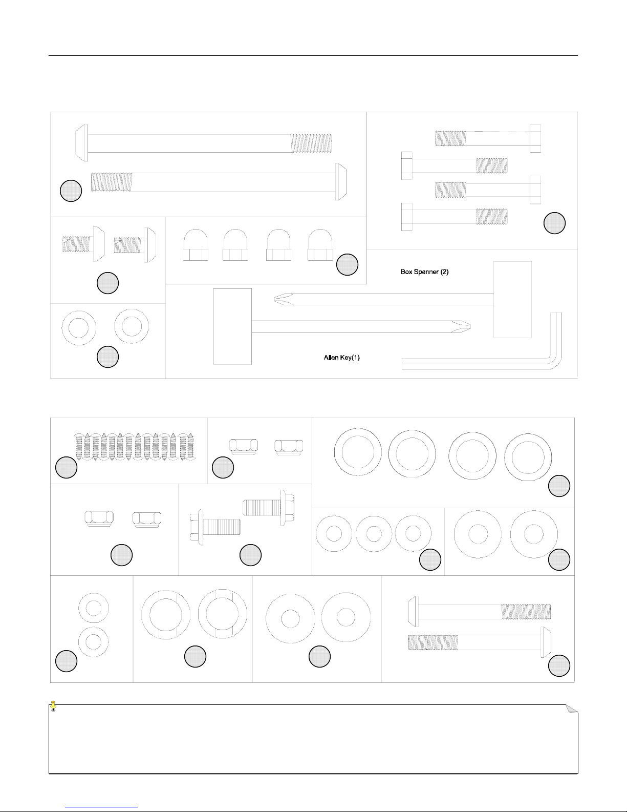
HARDWARE CHART
P
AGE 4
49
34
50
C44F HH
ARDWARE
ARDWARE
R
EFERENCE
R
EFERENCE
36
37
52
55 41
47
NOTE: Most of the listed assembly hardware has been packaged separately, but some hardware items have been
preinstalled in the identified assembly parts. In these instances, simply remove and reinstall the hardware as
assembly is required. Please reference the individual assembly steps and make note of all preinstalled hardware.
48
35 45
44 40
43
46
Page 6
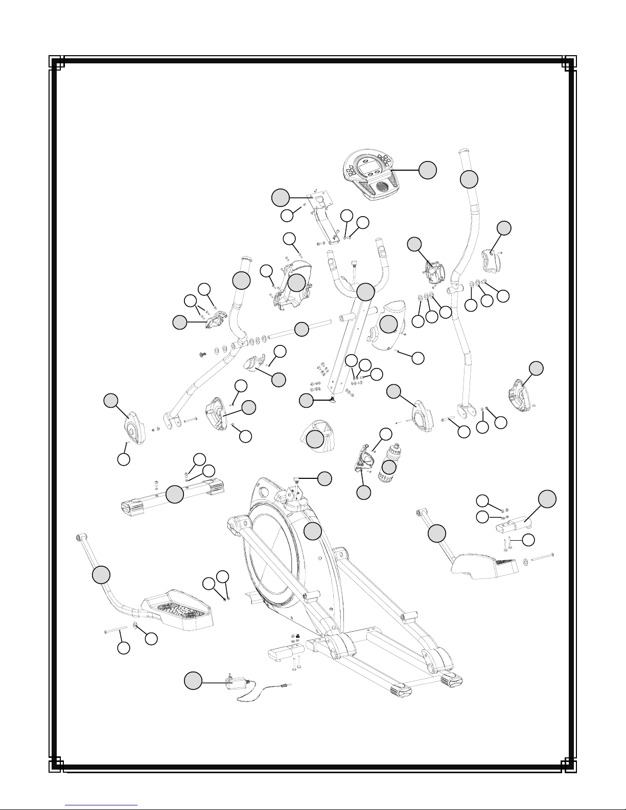
PAGE 5
EXPLODED PARTS VIEW
20
51
1
15
52
34
51
35
52
8
21
51
C44F PP
12
51
52
13
42
51
16
6
7
2
ARTS
ARTS
35 54
35
3
38
39
32
5
38
14
51
33
22
17
43
51
30
44
11
43
46
9
45
47
36
35
40
18
41
23
48
4
37
10
40
49
50
31
C
USTOMER
C
USTOMER
55
S
ERVICE
S
ERVICE
1-877-861-2181
Page 7
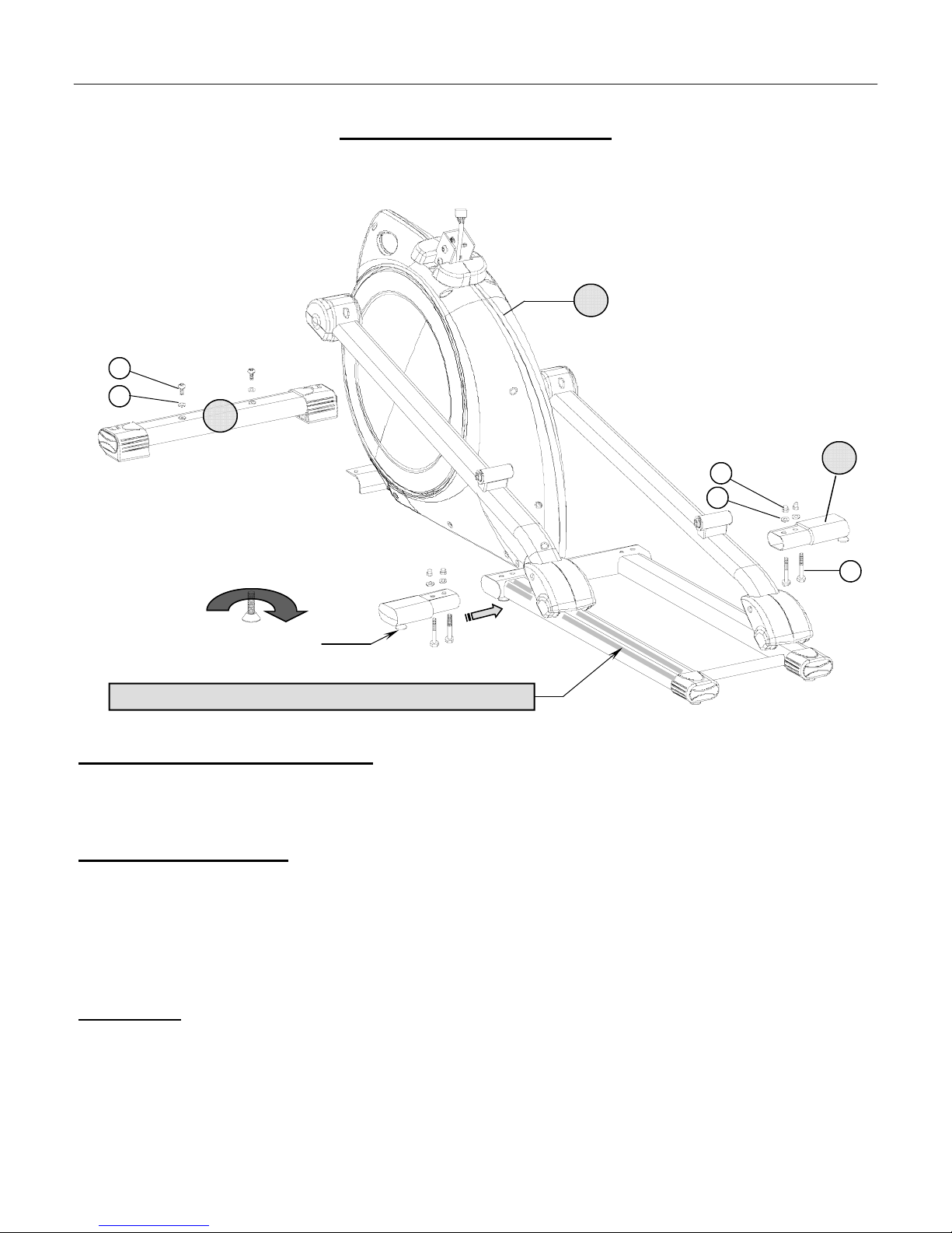
ASSEMBLY INSTRUCTION PAGE 6
ASSEMBLY STAGE #1
Attach Stabilizers to the Main Base
2
34
35
1
36
35
4
37
Recommended: Apply thin coat of silicon lubricant to the top of the base rails
ADJUSTMENT LEVELER
Assembly Hardware Required:
#34 Button Head Allen Bolt Qty. 2 #35 Flat Washer Qty. 6
#37 Hex Head Bolt Qty. 4 #36 Acorn Nut Qty. 4
Assembly Description:
A) Securely fasten the Front Stabilizer Assembly (#1) to the Base Assembly (#2) using 2-Button Head Allen Bolts (#34) and
2– Flat Washers (#35).
B) Attach the Stabilizer Extension Assemblies (#4) to the rear frame extrusion of the Base Assembly using 4-Hex Head Bolts
(#37), 4-Flat Washers (#35), and 4-Acorn Nuts (#36) as shown above.
Assembly Notes: Use the Adjustable Levelers located on the bottom of the Stabilizer End Caps to level the equipment and prevent
the base unit from rocking on an uneven surface.
We also recommend using a silicon lubricant to coat the base rails. This will smooth the travel of the pedal movement, as well as,
eliminate any tracking or noise problems that may be caused by the roller material.
♦ Assembly Stage #1 complete
Page 8
ASSEMBLY INSTRUCTION PAGE 7
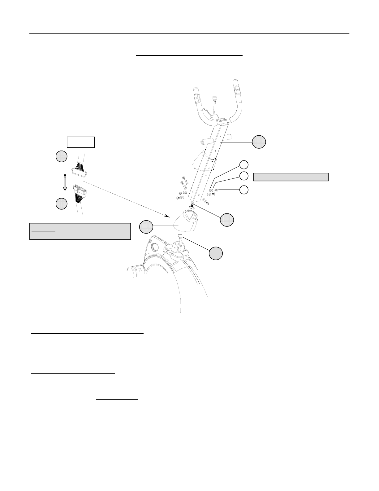
ASSEMBLY STAGE #2
Attach Handlebar Mast to the Main Base
Figure #1
6
3
Important: Be Careful Not to Pinch Cables
During Assembly
5
35
39
Hardware Preinstalled in Frame
38
6
7
3
Assembly Hardware Required
#35 Flat Washer* Qty. 7 #39 Spring (Lock) Washer* Qty. 7
#38 Button Head Allen Bolt* Qty. 7
Assembly Description:
A) Remove the preinstalled mounting hardware from the Base Assembly (#2). Slide the Shroud Boot (#7) over the Handlebar
Mast Assembly (#5). Assembly Note:
B) Connect the Upper Data Cable (#6) to the Lower Data Cable Assembly (#3) as shown in Figure 1.
C) Tuck the cable lengths inside the frame tubes and slide the Handlebar Mast Assembly (#5) down onto the Base Assembly
(#2). Align the mounting holes and secure the mast assembly in place using 7-Button Head Allen Bolts (#38), 7-Spring /
Lock Washers (#39), and 7-Flat Washers (#35) as shown.
♦ Assembly Stage #2 completed
: (*Hardware may be preinstalled in the Base Assembly)
For easier assembly tape the boot in place in the upper area of the mast.
Page 9

ASSEMBLY INSTRUCTION PAGE 8
ASSEMBLY STAGE #3
Attach Upper Pivot Arms to the Handlebar Mast
9
8
43
44
43
42
45
40
5
41
Assembly Hardware Required:
#40 Flat Washer Qty. 2 #44 Wave Washer Qty. 2
#41 Hex Head Flange Bolt Qty. 2 #45 Thin Teflon Washer Qty. 2
#43 Flat Washer Qty. 4
Assembly Description:
A) Slide the Threaded Pivot Shaft (#42) through the pivot-boss of the Handlebar Mast (#5). Over each end of the shaft slide
1-Flat Washer (#43), 1-Wave Washer (#44), and 1-Flat Washer (#43) following the orientation shown.
B) Slide the Left Pivot Arm Assembly (#8) over the end of the Pivot Shaft (#42). Secure the arm to the shaft using 1-Teflon
Washer (#45), 1-Flat Washer (#40), and 1-Hex Head Flange Bolt (#41) following the orientation shown. Note: Loosely
tighten the Flange Bolt until the Right Pivot Arm is in place.
C) Repeat the assembly reference for attaching the Right Pivot Arm Assembly (#9) to the Pivot Shaft (#42). Secure the arm in
place using 1-Teflon Washer (#45), 1-Flat Washer (#40), and 1-Hex Head Flange Bolt (#41) following the orientation
shown.
D) Fully tighten the mounting hardware for each pivot arm. Simultaneously tighten the mounting hardware by turning the Hex
Head Flange Bolts in opposite directions, as referenced by the arrows.
♦ Assembly Stage #3 completed
Page 10

ASSEMBLY INSTRUCTION PAGE 9
ASSEMBLY STAGE #4
Attach Pedal Arms
48 47
10
49
40
8
46
50
55
46
55
9
50
47
48
11
40
49
Assembly Hardware Required:
#40 Flat Washer Qty. 2 #49 Button Head Allen Bolt Qty. 2
#46 Button Head Allen Bolt Qty. 2 #50 Flat Washer Qty. 2
#47 Flat Washer Qty. 2 #55 Nylon Nut Qty. 2
#48 Nylon Nut Qty. 2
Assembly Description:
A) Assemble the Right & Left Pedal Arm Assemblies (#10 & 11) to Roller Arm Assemblies using 1-Button Head Allen Bolt
(#49),1-Flat Washer (#40), 1–Flat Washer (#50), and 1-Nylon Nut (#55) per side, following the orientation referenced
above.
B) Attach the front pivot point of the Pedal Arm Assemblies (#10 & 11) to the Pivot Arm As semblies (#8 & 9) using 1-Button
Head Allen Bolt (#46), 1-Flat Washer (#47), and 1-Nylon Nut (#48) per side, following the orientation referenced above.
♦ Assembly Stage #4 completed
Page 11

ASSEMBLY STAGE #5
Attach Plastic Covers
PAGE 10 ASSEMBLY INSTRUCTION
21
20
51
51
52
22
23
51
24
26
25
27
52
28
29
51
53
51
28
29
51
Assembly Hardware Required: (*Some Hardware Preinstalled in the Assembly Parts)
#51 Truss Screw* Qty. 4 #53 Self-threading Screw Qty. 2
#52 Self-threading Screw Qty. 12
Assembly Description:
Assembly Notes: Before attaching covers, check all pivot / roller mounting hardware to make sure it has been tightened
properly. Most of the lower covers will be already assembled. Use the drawing above as reference for any unassembled
covers. Use the proper orientation or all covers and assembly hardware.
A) (These covers may be preinstalled) Attach Roller Covers (#28 & 29) to the Roller Arm Assemblies using 2-Truss Screws
(#51) and1-Self-threading Screw (#53) per side, following the orientation referenced above.
B) (These covers may be preinstalled) Attach Roller Arm Pivot Covers (#24 / 25) & (#26 / 27) to the Roller Arm Assemblies
using 2-Truss Screws (#51) and 2-Self -threading Screws (#52) per side, following the orientation referenced above.
C) Attach Lower Pivot Arm Covers (#20 / 21) & (#22 / 23) to the Pivot Arm Assemblies using 2-Truss Screws (#51) and
2-Self-threading Screws (#52) per side, following the orientation referenced above.
♦ Assembly Stage #5 complete
Page 12

PAGE 11
ASSEMBLY INSTRUCTION
ASSEMBLY STAGE #6
Attach Computer & Upper Mast Covers to the Handlebar Mast
Figure #2
30
Back of the Computer
54
35
30
38
13
12
51
52
14
6
51
19
5
Assembly Hardware Required: (*Hardware Preinstalled in the Assembly Parts)
#35 Flat Washer* Qty. 3 #52 Self-Threading Screw Qty. 6
#38 Button Head Allen Bolt* Qty. 3 #54 Truss Screw* Qty. 4
#51 Truss Screw* Qty, 4
Assembly Description:
A) Slide the Rear Pivot Cover (#13) over the end of the Computer Mounting Bracket (#12). Route the Heart Rate Cable(#19)
and Upper Data Cable (#6) through the mounting bracket. Secure the Mounting Bracket (to the u-bracket on the back of the
Handlebar Mast Assembly (#5) using 3-Button Head Allen Bolts (#38) and 3-Flat Washers (#35). Assembly Note:
mounting hardware may be preinstalled in the assembly location and not included as part of the packaged assembly hardware.
B) As referenced above in Figure # 2; connect the Heart Rate Cable Assembly (#19) to the receptacle cable on the back of the
computer housing. Plug the Upper Data Cable (#6) into the board mounted connector on the back of the computer. Tuck the
excess cable length into the mounting bracket and attach the Computer (#30) to the mounting bracket using 4-Truss Screws
(#54). Assembly Note
: The mounting hardware may be preinstalled in the back of the computer housing and not included in
the packaged assembly hardware.
C) Align the Upper (Front & Rear) Mast Covers (#13 & #14) and secure in place using 4-Truss Screws (#51) and
6 -Self-Threading Screws (#52).
♦ Assembly Stage #6 completed
The
Page 13

ASSEMBLY STAGE #7
Attach Upper Pivot Covers & Water Bottle Cage
PAGE 12 ASSEMBLY INSTRUCTION
51
52
51
15
16
32
Assembly Hardware Required: (*Hardware Preinstalled in the Assembly Parts)
18
17
33
51
#51 Truss Screw* Qty. 4 #52 Self-threading Screw Qty. 4
Assembly Description:
Assembly Note: Before attaching the Pivot Covers, check the Pivot Arm mounting hardware to make sure it has been
tightened properly.
A) Mount the Upper Front Pivot Covers (#16 & #18) to the front end of the Pi vot Arms (#8 & #9) using 1-Truss Screw* per
cover.
B) Attach the Upper Rear Pivot Covers (#15 & #17) using 1-Truss Screw* (#51) and 2-Self-Threading Screws (#52) per side
as shown.
C) Attach the Bottle Cage (#32) to the Handlebar Mast (#5) using the 2-previously installed Truss Screws (#51). Once the cage
has been mounted, insert the Sports Bottle (#33).
♦ Assembly Stage #7 complete
Page 14

PAGE 13 ASSEMBLY INSTRUCTION
ASSEMBLY STAGE #8
Supplying Power
Reference the Front of the Base Assembly
31
Assembly Description:
This product requires AC voltage to operate properly.
Assembly Caution: The Adapter converts AC voltage to a low DC output. The Adapter can be shorted if it is improperly grounded
while plugging it into a wall outlet. If the AC adapter becomes hot upon plugging it into the wall or product, stop usage
immediately. Shorted adapters will need to be replaced.
AC Adapter Operation:
A) Plug in the cord end of the AC Adapter (#31) into the receptacle located on front of the Base Assembly / shroud.
B) Plug the AC Adapter into an available wall outlet. Safety Precaution: For added component life and safety around
children, unplug the AC Adapter from the wall when product is not in use. This will cut the power to the unit, but be
aware that the pedals will still be able to move on the base rails.
Helpful Reminders
♦ Take the time to reference additional information regarding computer operation, product maintenance, and related warranty
information.
♦ Note the shroud orientation of AC adapter receptacle. The receptacle (shroud) location will vary per product model. Arrange
placement of the unit so the AC adapter can easily reach the receptacle and an outlet plug.
You have successfully completed the assembly of this product and you are ready to start exercising toward a healthier lifestyle!
C
USTOMER
C
USTOMER
Congratulations !
S
ERVICE
S
ERVICE
1-877-861-2181
Page 15

COMPUTER OPERATION PAGE 14
B
C
A
D
C
OMPUTER
C
OMPUTER
N
E
I
NSTRUCTION
I
NSTRUCTION
M
F
J
G
K
H
I
L
O
BUTTON / INPUT FUNCTIONS
NOTE: THESE ARE THE BASIC OPERATING FUNCTIONS OF EACH BUTTON. ACTUAL PROGRAMMING MAY REQUIRE A
ACTIVATION SEQUENCE OF MORE THAN ONE BUTTON
[A] ENTER SELECTS & SETS DISPLAY FUNCTIONS. HOLDING THE ENTER BUTTON DOWN WILL ACTIVATE A
TOTAL DISPLAY RESET (ZERO-OUT VALUES). NOTE: PRESET TARGET VALUES WILL RESET TO THE
CUSTOMIZED SETTINGS.
(REFERENCE PROGRAM DESCRIPTIONS ON PAGE 17).
[B]
START / STOP ACTIVATES & STOPS COMPUTER FUNCTIONS.
[C] PERSONAL SELECTS USER IDENTIFICATION CODES (U0-U4).
[D] UP SELECTS PROGRAM MODE & ADJUST (INCREASES) DISPLAY SETTINGS.
DOWN SELECTS PROGRAM MODE & ADJUST (DECREASES) DISPLAY SETTINGS.
[E]
MANUAL ACTIVATES MANUAL TRAINING PROGRAM.
[F]
[G] USER ACTIVATES USER TRAINING PROGRAM.
[H] WATT ACTIVATES WATT CONSTANT TRAINING PROGRAM.
FITNESS TEST ACTIVATES FITNESS LEVEL EVALUATION
[I]
[J]
PROGRAM ACTIVATES PREPROGRAMMED PROFILE TRAINING.
HEART RATE ACTIVATES HEART RATE TRAINING MODE.
[K]
RECOVERY THE RECOVERY BUTTON ALLOWS USERS TO EVALUATE THEIR FITNESS LEVEL AFTER COMPLETING
[L]
A TRAINING SESSION.
[M] BODY FAT % DISPLAYS BODY FAT % AND BODY MASS INDEX (BMI) READINGS BASED ON A USER’S BODY
COMPOSITION. READING CAN BE OBTAINED AFTER COMPLETION OF A TRAINING PROGRAM.
[N] FAN ON / OFF OPERATES COMPUTER FAN.
MEDIA INPUT OFFERS AN OPTION OF PLAYING ELECTRONIC DEVICES (CD & MP3 PLAYERS) THROUGH
[O]
COMPUTER SPEAKERS. (INPUT CABLE IS NOT INCLUDED)
SPECIAL FEATURE
AUTO SHUT-OFF COMPUTER WILL AUTOMATICALLY SHUT-OFF AFTER 4 MINUTES OF NOT RECEIVING A PEDAL
SENSOR READING. NOTE: DURING SHUT-OFF MODE ALL PRESET VALUES WILL BE KEPT. PRESS THE
ENTER BUTTON OR START PEDALING TO ACTIVATE THE COMPUTER.
Page 16

PAGE 15
2.3
2.1
C
OMPUTER
C
OMPUTER
I
NSTRUCTION
I
NSTRUCTION
COMPUTER OPERATION
2.2
RESISTANCE / PROFILE GRID
2.4
DISPLAY CHARACTERS SHOWN AS REFERENCE ONLY
1) ACTIVATION (START UP)
MAKE SURE THE AC ADAPTER IS PROPERLY PLUGGED INTO A WALL OUTLET. PRESS ANY FUNCTION BUTTON
OR START PEDALING TO ACTIVATE DISPLAY. A BEEP WILL SOUND AND THE DISPLAY WILL ILLUMINATE .
2) SET UP STEPS
2.1 ONCE ACTIVATED, THE DISPLAY WILL SHOW A SCREEN WITH STOP BLINKING IN THE LOWER LEFT CORNER
AND A USER ID CODE (U0-U4) BLINKING IN THE UPPER LEFT CORNER. AT THIS POINT A USER ID MUST BE
SELECTED; USE THE PERSONAL BUTTON TO SCROLL THROUGH THE USER ID OPTIONS AND PRESS THE ENTER
BUTTON TO LOCK IN THE DESIRED USER ID.
U0 = QUICKER SETUP PROCESS WITH LIMITED PROGRAMMING OPTIONS.
U1– U4 = MORE PROGRAMMING OPTIONS INCLUDING CUSTOMIZED DATA ENTRY.
2.2 IF USER ID CODE U1-U4 IS CHOSEN, THE USER WILL BE PROMPTED (BLINKING DISPLAY TEXT) TO ENTER
PERSONAL DATA (GENDER, AGE, HEIGHT, AND WEIGHT). THIS DATA WILL BE USED TO CALIBRATE THE
TRAINING PROGRAMS.
IF USER ID U0 IS CHOSEN, THE DISPLAY WILL AUTOMATICALLY SKIP PERSONAL DATA ENTRIES AND MOVE
TO THE TRAINING PROGRAM SELECTIONS.
2.3 ONCE THE USER ID IS DEFINED AND PERSONAL DATA IS ENTERED, THE USER WILL BE PROMPTED (BLINKING
TEXT) TO SELECT A TRAINING PROGRAM (MANUAL, FITNESS TEST, WATT, PROGRAM, HEART RATE CONTROL.,
OR USER). ALL PROGRAM HEADINGS WILL BE LISTED ACROSS THE TOP OF THE SCREEN. THE PROGRAM
SELECTION WILL VARY DEPENDING ON THE USER ID SELECTED. PUSH THE CORRESPONDING BUTTON (ON THE
RIGHT SIDE OF THE COMPUTER) TO CHOOSE A DESIRED PROGRAM. (See page 18)
INDIVIDUAL DISPLAY FUNCTIONS (TIME, DISTANCE, CALORIE, AND HEART RATE). THESE TARGET VALUES
WILL BE IDENTIFIED WITH BLINKING TEXT. USE THE UP OR DOWN BUTTON TO ADJUST VALUES AND PRESS
THE ENTER BUTTON TO LOCK IN THE DESIRED PRESETS. THE ENTER BUTTON CAN ALSO BE USED TO SCROLL
THROUGH EACH TARGET WINDOW OR A USER CAN SKIP ALL TARGET SET UP BY PUSHING THE START / STOP
TO BEGIN TRAINING. NOTE: DISPLAY FUNCTIONS WILL COUNT UP FROM ZERO WHEN NO VALUES ARE PRESET.
QUICK START
BUTTON AND BEGIN TRAINING. ALL DISPLAY VALUES WILL COUNT UP FROM ZERO, UNLESS PRESET VALUES
WERE PREVIOUSLY ENTERED. NOTE: IF USING U0 USER ID; PRESS THE START / STOP BUTTON. THE COMPUTER
WILL AUTOMATICALLY GO INTO MANUAL TRAINING MODE.
RESISTANCE
TO CHOOSE FROM 1-16 LEVELS OF VARIED RESISTANCE. A USER CAN ADJUST RESISTANCE AT ANY TIME
DURING A TRAINING MODE BY PUSHING THE UP / DOWN BUTTONS (THE EXCEPTION WOULD BE THE TARGET
HEART RATE MODE). NOTE: PREPROGRAMMED TRAINING PROFILES WILL NOT ALLOW THE RESISTANCE
LEVELS TO BE ADJUSTED BEYOND THE MINIMAL SETTINGS
ERROR CODES
E2 = BAD DATA CABLE CONNECTION. (See page 19)
2.4 AFTER SELECTING A TRAINING MODE, THE USER WILL HAVE THE OPTION TO PRESET TARGET VALUES FOR THE
AFTER A USER ID IS CHOSEN, PRESS THE MANUAL PROGRAM BUTTON. NEXT; PRESS THE START / STOP
PRODUCT IS EQUIPPED WITH AN ADJUSTABLE RESISTANCE MECHANISM. THIS FEATURE WILL ALLOW A USER
E1 = BODY FAT MEASUREMENT FAILED DUE TO INCORRECT HEART RATE READING. (See page 19)
Page 17

PAGE 16 COMPUTER OPERATION
C
OMPUTER
C
OMPUTER
I
NSTRUCTION
I
NSTRUCTION
DISPLAY FUNCTIONS / READINGS
TIME COMPUTER DISPLAY WILL ACCUMULATE TOTAL TRAINING TIME IN 00:00 (MINUTES : SECONDS). COMPUTER
WILL COUNT UP TO, OR DOWN FROM , A MAXIMUM READING OF 99:59.
PRESET TARGET TRAINING TIME: USE THE ENTER BUTTON TO SCROLL TO THE TIME FUNCTION AND USE
THE UP / DOWN BUTTONS TO ADJUST THE SETTING. SETTINGS WILL BE ENTERED IN 1:00 MINUTE INCREMENTS
AND THE COMPUTER WILL COUNT DOWN FROM THE SET TIME. ONCE THE DESIRED TIME IS SET, PRESS START /
STOP BUTTON TO BEGIN TRAINING. ONCE A SET TRAINING TIME IS COMPLETED, THE COMPUTER WILL “BEEP”
FOR APPROXIMATELY 8 SECONDS AND COMPUTER WILL RESET TO THE INITIAL SETTING.
SPEED THE COMPUTER WILL REGISTER AND DISPLAY TRAINING SPEED (MPH).
RPM THE COMPUTER WILL READ AND DISPLAY PEDAL / DRIVE TRAIN ROTATIONS.
DISTANCE THE COMPUTER ACCUMULATES TRAINING DISTANCE FROM 0.00 TO A MAXIMUM OF 99.90 MILES. EACH
INCREMENT WILL BE DISPLAYED IN 0.01 MILE.
PRESET A TARGET TRAINING DISTANCE: USE THE ENTER BUTTON TO SCROLL TO THE DISTANCE FUNCTION
WINDOW AND USE THE UP / DOWN BUTTONS TO ADJUST THE SETTING. EACH SETTING WILL BE IN
INCREMENTS OF 0.10 MILE AND THE COMPUTER WILL COUNT DOWN FROM THE SET DISTANCE. ONCE THE
DESIRED DISTANCE IS SET, PRESS THE START / STOP BUTTON TO BEGIN TRAINING. ONCE A TARGET DISTANCE
IS ACHIEVED, THE COMPUTER WILL “BEEP” FOR APPROXIMATELY 8 SECONDS AND RESET TO THE INITIAL
SETTINGS.
CALORIE COMPUTER ACCUMULATES TOTAL CALORIE CONSUMPTION (BURN) DURING A TRAINING PERIOD. COMPUTER
WILL COUNT IN 1 CALORIE INCREMENTS, FROM 0 TO A MAXIMUM READING OF 9990 CALORIES.
PRESET A TARGET CALORIE BURN: USE THE ENTER BUTTON TO SCROLL TO THE CALORIE FUNCTION AN USE
THE UP / DOWN BUTTONS TO ADJUST THE SETTING. ADJUSTED VALUES WILL BE ENTERED IN INCREMENTS OF
10 CALORIES AND THE COMPUTER WILL COUNT DOWN FROM THE SET CALORIE BURN. ONCE THE CALORIE
FUNCTION IS SET, PRESS START / STOP BUTTON TO BEGIN TRAINING. ONCE THE TARGET CALORIE BURN IS
ACHIEVED, THE COMPUTER WILL “BEEP” FOR APPROXIMATELY 8 SECONDS AND THEN RESET TO THE
ORIGINAL SETTING.
NOTE: THE REPORTED CALORIE DATA IS ONLY A REFERENCE GUIDE FOR THE USER. IT SHOULD NOT BE USED
IN COMPARISON OF CALIBRATED MEDICAL EQUIPMENT.
PULSE THE COMPUTER CAN DISPLAY A USER'S HEART RATE READING. A BLINKING HEART SYMBOL & NUMERIC
READING WILL BE DISPLAYED ON THE COMPUTER AS LONG AS A USER’S HANDS ARE LOCATED ON THE GRIP
SENSORS. READINGS WILL APPEAR WITHIN 30 SECONDS TO 1 MINUTE OF CONSISTENT GRIP CONTACT.
READINGS WILL BECOME INCONSISTENT IF A USER FAILS TO LEAVE BOTH HANDS IN CONTACT WITH THE GRIP
SENSORS.
PRESET A TARGET HEART RATE: USE THE ENTER BUTTON TO SCROLL TO THE HEART RATE FUNCTION AND
PRESS THE UP / DOWN BUTTONS TO ADJUST THE SETTING. PULSE SETTINGS WILL BE FROM 30 - 240 BPM.
ONCE THE DESIRED HEART RATE IS SET PRESS THE START / STOP BUTTON TO BEGIN TRAINING. IF A USER
EXCEEDS THE SET TARGET HEART RATE , THE COMPUTER WILL “BEEP” TO REMIND THE USER OF THE PRESET
LIMIT.
NOTE: HEART RATE READINGS ARE ONLY A REFERENCE OF A USER’S PULSE RATE DURING TRAINING. THESE
READOUTS SHOULD NOT BE USED IN COMPARISON WITH CALIBRATED MEDICAL EQUIPMENT. SOME USERS
MAY EXPERIENCE INCONSISTENCIES IN READINGS DUE TO THE NATURE OF THEIR PHYSICAL CONDITION.
WATT THE COMPUTER WILL MEASURE A USER’S TRAINING OUTPUT (WORKLOAD). THE COMPUTER WILL
AUTOMATICALLY CONFIGURE AND DISPLAY WATT READINGS DURING ALL TRAINING MODES. READINGS
WILL BE DISPLAYED IN 1-WATT INCREMENTS. (Refer to the WATT program to train using a preprogrammed setting)
RECOVERY THE COMPUTER WILL ALLOW A USER TO EVALUATE THEIR FITNESS LEVEL AFTER COMPLETING A TRAINING
SESSION. THE EVALUATION IS BASED ON A USER’S HEART RATE RECOVERY. ACTIVATION: AFTER
COMPLETING A TRAINING SESSION, PRESS THE RECOVERY BUTTON AND PLACE PALMS OF BOTH HANDS ON
THE SENSOR GRIPS. THE COMPUTER WILL AUTOMATICALLY STOP ALL DISPLAY FUNCTIONS EXCEPT “TIME”,
WHICH WILL START COUNTING DOWN FROM 60 SECONDS. ONCE THE COUNT DOWN IS COMPLETED, THE USER
CAN REMOVE THEIR HANDS FROM THE SENSOR GRIPS. THE BOTTOM DISPLAY WILL SHOW A RATING OF F1– F6.
AN “F1” READING IS THE BEST RATING POSSIBLE. USERS CAN MONITOR THEMSELVES AFTER EACH TRAINING
SESSION AND USE THE RECOVERY READING AS A GAUGE FOR CARDIO CONDITIONING.
NOTE: PRESS THE RECOVERY BUTTON AGAIN TO RETURN TO THE MAIN DISPLAY.
Page 18

COMPUTER OPERATION PAGE 17
DISPLAY FUNCTION / READINGS (Continue d)
BODY FAT % THE COMPUTER WILL ALLOW A USER TO MEASURE THEIR BODY COMPOSITION BASED ON BODY FAT & BODY
MASS INDEX (BMI) EVALUATION. THE READINGS ARE CALCULATED USING A COMBINATION OF USER ENTRY
DATA (HEIGHT, WEIGHT, AGE, & GENDER) AND HEART RATE SAMPLING. ACTIVATION: AFTER COMPLETING
A TRAINING PROGRAM PRESS THE “BODY FAT %” BUTTON AND PLACE THE PALMS OF BOTH HANDS ON THE
HEART RATE GRIP (SENSORS). E-1 ERROR CODE WILL APPEAR ON THE DISPLAY IF BOTH HANDS ARE NOT
PLACED IN PROPER POSITION ON THE SENSORS. THE FOLLOWING SEQUENCE OF READINGS WILL APPEAR ON
THE DISPLAY WITHIN 10 SECONDS OF RECEIVING A HEART RATE SIGNAL:
(1ST #) BODY FAT %: PERCENTAGE OF FAT TISSUE VERSUS LEAN MUSCLE MASS OF USERS TOTAL BODYWEIGHT.
(2ND #) BODY MASS INDEX (BMI): CALCULATED NUMBER USED TO DETERMINE HEALTHY WEIGHT RANGES.
(SYMBOL) BODY COMPOSITION SYMBOL: HEALTH RATING BASED ON BODY FAT AND BODY MASS READING.
BODY FAT %
MALE < 13% 14 - 17% 18 - 25% 26% >
FEMALE < 20% 21 - 24% 25 - 31% 32% >
EXCELLENT GOOD FAIR POOR
C
OMPUTER
C
OMPUTER
REFERENCE CHARTS
I
NSTRUCTION
I
NSTRUCTION
BODY MASS INDEX (BMI)
< 20 20 - 24.9 25 - 29.9 30 >
BODY COMPOSITION
SUMMARY BODY FAT AND BODY MASS MEASUREMENTS ARE RECOGNIZED AS ESSENTIAL FACTORS IN
ACCESSING A PERSONS PHYSICAL CONDITION. HIGHER READINGS ARE FLAGS TO POTENTIAL
WEIGHT RELATED HEALTH RISK. THESE RISK INCLUDE, BUT ARE NOT LIMITED TO; HEART DISEASE,
HIGH BLOOD PRESSURE, DIABETES, AND OSTEOARTHRITIS.
ANOTHER IMPORTANT FACTOR IS THAT MUSCLE TISSUE WEIGHS MORE THAN FAT TISSUE. CERTAIN
TYPES OF EXERCISE WILL BUILD MUSCLE MASS. MUSCLED TONED INDIVIDUALS MAY HAVE A
LOWER BODY FAT PERCENTAGE, BUT REGISTER HIGHER BODY MASS (BMI) READINGS. BASED ON
STANDARD WEIGHT CHARTS THESE INDIVIDUALS MAY BE CONSIDERED OVERWEIGHT, BUT BASED
ON OVERALL BODY COMPOSITION, WOULD BE LABELED AS FIT INDIVIDUALS.
PHYSICAL ACTIVITY AND GOOD NUTRITION ARE KEY FACTORS TO MAINTAINING A HEALTHIER
LIFESTYLE. CONSISTENT CARDIOVASCULAR EXERCISE WILL LEAD TO THE GREATEST METABOLISM
(BURNING) OF FAT. BY KEEPING BODY FAT LEVELS IN AN ACCEPTABLE RANGE, YOU WILL LOOK AND
FEEL BETTER. MAKE SURE TO SET REALISTIC FITNESS GOALS AND DEVELOP A TRAINING REGIMENT
THAT WORKS BEST YOU.
THE READINGS FROM THIS PRODUCT ARE OFFERED AS A POINT OF REFERENCE IN DEVELOPING
TRAINING METHODS WHICH ARE BENEFICIAL TO ACHIEVING FITNESS GOALS. READINGS SHOULD
ONLY BE USED AS A TRAINING GAUGE AND NOT BE CONSIDERED AS A REPLACEMENT FOR
PROFESSIONAL MEDICAL ADVISE. IT IS A IMPORTANT TO NOTE; BODY FAT AND BODY MASS ARE
ONLY PART OF A PERSON’S HEALTH PROFILE. WE RECOMMEND TALKING TO YOUR PERSONAL
PHYSICIAN ABOUT OTHER MEASURES AND ASSOCIATED HEALTH FACTORS.
UNDERWEIGHT IDEAL WEIGHT OVERWEIGHT HIGH RISK
(SYMBOL)
ATHLETE FIT ACCEPTABLE NEEDS IMPROVEMENT
Page 19

PAGE 18 COMPUTER OPERATION
T
RAINING
T
RAINING
P
ROGRAMS
P
ROGRAMS
SELECTING A TRAINING PROGRAM
Once a User ID is set up, the computer will list six available training programs across the top of the display (Manual, User, Watt, Fitness, Program, or Target
Heart Rate). The user may select one of the six programs by pressing the corresponding button on the right side of the computer face or simply press the
START / STOP button to begin training in a MANUAL Mode. Reference the instructions listed below to set up and activate a desired program.
♦ MANUAL MODE - S tandard Program
Activation Procedure: 1) Press the MANUAL Program button. 2) Use the UP / DOWN buttons to adjust the resistance level and press the ENTER
button to set the desired level (see reference below). 3) Use the UP / DOWN buttons to preset (adjust) individual target values (time, distance, calories,
etc.) or press the START / STOP button to begin training.
Manual Resistance Adjustment: The display will reference 1-16 levels of training resistance. Level 16 will be highest resistance setting. Use the UP /
DOWN buttons to select a desired resistance setting. The display graph will change as resistance levels are changed (adjusted). Each row (segment)
equals one level of resistance. Reference numbers will appear on left side of the row segments. Once a resistance level is selected, press the ENTER
button.
be adjusted anytime during training by pressing the UP / DOWN buttons.
♦ U
SER MODE - Set Up a Customiz ed Training Grid (Note:This program option cannot be used with U0 -User ID Selection)
Activation Procedure: 1) Press the USER program button. 2) Set a customized training Profile (referenced below). 3) Hold down the ENTER button
for approximately 2 seconds to preset target values or press the START / STOP button to begin training.
Setting a Customized Training Profile: The lower display will reference 16 individual profile (resistance) columns. Each column can be set to an
individual resistance level (1-16). The UP & DOWN buttons will adjust the number resistance bars (segments) per column. After a column has
been preset (adjusted), press the ENTER button. This can be done until all 16 columns have been customized (preset).
♦ WATT CONSTANT– Resistance Training Based on Preprog rammed Watt Settings
Activation Procedure: 1) Press the WATT CONSTANT program button. 2) Select a Watt setting (referenced below). 3) Use the UP / DOWN
buttons to preset target values or push the START / STOP button to begin training.
Selecting a Watt setting: The upper left window will reference Watt settings (120 - 350). Use the UP / DOWN buttons to make a selection. Settings
will be in increments of 10. Higher Watt settings will equal higher resistance levels. Press the ENTER button to lock in the setting. Note: Resistance
levels cannot be adjusted during the WATT training mode. Users must maintain a speed output that corresponds with the Watt setting. Resistance levels
will automatically adjust based on a user’s speed. If the user speed is lower than needed to maintain a Watt setting, the resistance will increase. If the
user maintains a speed higher than the selected Watt setting, the resistance will decrease.
Note: If a target value is preset in Manual mode, the resistance will automatically adjust to match the preset target values. Resistance levels can
♦ F
ITNESS TEST - Performance Evaluation Program (Note:This program option cannot be used with U0 -User ID Selection.)
Activation Procedure: 1) Press the FITNESS TEST program button. 2) Press the START / STOP button to begin training
Program Summary: User evaluation is based on a preset 12 minute training period. The other target values will be based on the initial user data
(gender & age). Target values and resistance level cannot be adjusted . A Fitness rating (F1-F5) will appear in the upper left of the display, at the
completion of the training program. An F1 reading is the best possible rating, while F5 would be the worst. Note: A Heart rate reading is used as part of
the evaluation formula. User’s must maintain grip contact during the training session to receive an accurate performance assessment.
♦ P
ROGRAM MODE - Preprogrammed Training Grids
Activation Procedure: 1) Press the PROGRAM button 2) Use the UP / DOWN buttons to select one of the preprogrammed training profiles P1-P9
(referenced below) 3) Press the ENTER button to lock in a selected profile. 4) Use the UP / DOWN buttons to preset target values or push the
START / STOP button to begin training.
Selecting a Training Profile: The computer has 9 programmed training (resistance) profiles (referenced P1-P9). Use the UP / DOWN buttons to
scroll through the training profiles. Once a training profile is selected, press the ENTER button to lock in the profile.
♦ TARGET HEART RATE MODE -Training Based on Target Heart Rate Zones (Note:This program option cannot be used with U0 -User ID Selection.)
Activation Procedure: 1) Press HEART RATE Program button 2) Use the UP / DOWN buttons to select a heart rate training zone (referenced
below) 3) Press the START / STOP button to begin training or use the UP / DOWN buttons to preset function targets.
Setting a HR Training Zone: Zone training is based on exercising within a set percentage of a users maximum heart rate. A users maximum
heart rate is based on a basic formula; (220 BPM - Users Age = Maximum HR). After activating the Heart Rate Mode, use the UP / DOWN buttons
to select one of the HR training percentage referenced in the upper display area (55%, 75% , 90%,). Press the ENTER button to lock in the desired
zone setting. Note: Users may also set a customized HR target by selecting TAG (target) and using the UP /DOWN buttons to set zone parameters.
Note: The resistance will auto-adjust according heart rate presets. If a user’s heart rates falls under the preset targets, the resistance auto- adjust up
one level every 30-seconds until target rate is achieved. If a users heart rate exceeds the target presets, the computer will auto-adjust down the resistance
one level until target is reached. For training safety, the computer will stop functioning and beep, if a user continues to exceed a target heart rate for
more than 30-seconds at the lowest resistance training level.
Page 20

PAGE 19
BASIC TROUBLESHOOTING TIPS
BASIC TROUBLESHOOTING TIPS
TROUBLESHOOTING
PROBLEM DESCRIPTION
1. NO DISPLAY
(E-2 ERROR CODE)
2. POWER, BUT NO COMPUTER
READINGS
1.1
1.2
1.3
1.4
1.5
*
2.1
2.2
CHECK AC ADAPTER FOR PROPER VOLTAGE OUTPUT (9-12 VDC).
INSPECT RECEPTACLE ON THE FRONT OF THE UNIT FOR DAMAGE.
CHECK CABLE CONNECTIONS: MAKE SURE CONNECTIONS ARE SECURE
AND IN THE CORRECT ORIENTATION.
CHECK CABLE ASSEMBLIES FOR DAMAGE: PINCH POINTS & POSSIBLE
SHORTING OF WIRES.
CHECK FOR POSSIBLE COMPUTER DAMAGE: CRACKED DISPLAY WINDOW
(BLACK SCREEN).
If computer still fails to operate after checking these suggestions, contact us for
technical support.
CHECK COMPUTER CONNECTION: MAKE SURE CONNECTORS ARE SECURE
AND IN THE CORRECT ORIENTATION.
CHECK FOR THE POSSIBILITY OF PINCHED WIRES, WHICH COULD SHORT
CABLE CONNECTION.
SUGGESTED SOLUTION
3. PRODUCT WILL NOT SIT LEVEL
4. PIVOT ARM / FOOT PEDAL
WOBBLE
5. ROLLER NOISE OR TRACKING
PROBLEM
6. ERRATIC HEART RATE
(E-1 ERROR CODE)
USE LEVELERS ON THE BOTTOM OF THE STABILIZERS TO ADJUST
3.1
EQUIPMENT TO UNEVEN SURFACES.
CHECK TO MAKE SURE ALL CORRESPONDING PIVOT MOUNTING
4.1
HARDWARE HAS BEEN SECURELY TIGHTENED.
REVIEW ASSEMBLY STEPS AND MOUNTING HARDWARE
4.2
LUBRICATE THE TOP OF THE BASE RAILS WITH SILICON LUBRICANT.
5.1
MAKE SURE PALMS OF HAND ARE CENTERED ON GRIP SENSORS.
6.1
CHECK CABLE CONNECTIONS FROM HANDLE BAR ASSEMBLY TO THE
6.2
COMPUTER.
NOTE: ELLIPTICAL UNITS OPERATE WITH AN AGGRESSIVE USER
MOVEMENT. THIS SOMETIMES EFFECTS THE CONSISTENCY IN USER’S HAND
PLACEMENT ON THE GRIPS. IF HR READINGS ARE RAPIDLY FLUCTUATING;
SLOW DOWN TRAINING STRIDE AND CONCENTRATE ON CONSISTENT HAND
PLACEMENT ON THE GRIP SENSORS.
NOTE: A USER'S PHYSICAL CONDITION CAN EFFECT THE ACCURACY OF A
READING, AS WELL AS, UNCONTROLLABLE INTERFERENCES.
Make sure to reference the assembly steps & parts information in this manual when performing any troubleshooting.
If you experience other technical problems that are not listed or have additional questions, please contact us : 1.877.861.2181
Page 21

PREVENTATIVE MAINTENANCE PAGE 20
E
QUIPMENT
E
QUIPMENT
♦ Use a dampened soft-cloth to wipe equipment free of perspiration after each use. Avoid getting
excessive moisture on computer or electronic components. Do not use abrasive cleaners or
petroleum-based solvents to clean equipment.
♦ Do not remove drive train shrouds or attempt any technical service on equipment without consulting
an authorized service representative.
♦ Regularly inspect product for lose assembly hardware and worn components. Tighten and replace as
needed.
♦ (If applicable) For added safety, unplug equipment from the wall socket when it is not being used.
♦ Use a product /exercise mat underneath equipment for protection of floors & carpets.
♦ (If applicable) Apply recommended component lubricants at the required time periods.
♦ Keep product assembly manual, purchase receipt, and service records in a safe storage place.
♦ ( If applicable) Periodically check batteries for proper voltage output & replace as needed.
♦ Do not store or use equipment outdoors.
♦ Moving equipment:
M
AINTENANCE
M
AINTENANCE
Elliptical models; carefully lift the rear stabilizer tube and steer the equipment to the desired
location. Do not pull on pivot arms or computer to move equipment.
T
RAINING
T
RAINING
How you start an exercise program depends on your physical condition. If you have been inactive for
awhile or you have pre-existing health condition, you should start slowly. Initially you may only be able
to exercise for a short amount of time using minimal resistance levels or weight loads.
Begin your desired training program slowly and gradually increase the amount of time you exercise.
Apply realistic goals, that have been set by you or your physician. You should see sufficient gains in
your personal fitness level within 6-8 weeks of continuous exercise, but do not be discouraged if it takes
longer. It is very important to exercise at your own pace and become confident in obtaining your goals.
It is also important to apply warm-up, stretching, and cool down periods with any exercise program.
As your fitness level increases, so will your confidence and sense of accomplishment. Regular exercise
and a healthy diet will energize you and offer a sense of well-being.
F
F
OR
OR
S
UCCESS
S
UCCESS
C
USTOMER
C
USTOMER
S
ERVICE
S
ERVICE
877--
11--877
861--
861
2181
2181
Page 22

PAGE 21
General Terms & Conditions
All LAMAR Health, Fitness & Sports, LLC exercise products are
warranted to be free from defects in materials and workmanship
under the terms of recommended use and warranty coverage.
Warranty coverage is valid to the original retail purchaser and is not
transferable. Coverage will be calculated from the date of retail
purchase. Original proof of purchase and serial number identification
will be required with any associated warranty claim.
Coverage periods & warranty terms may vary per product model.
Applied warranties will be based on type of product, components,
and recommended application (use environment). Products sold or
placed in non-recommended user applications will void all warranty
coverage set forth by LAMAR Health, Fitness & Sports, LLC.
Coverage Periods
LAMAR Health, Fitness & Sports, LLC hereby extends the following
limited warranties for the application, components, and time periods
indicated;
User Environment: Residential
Structural Frame: Lifetime (Limited)
Mechanical Parts: 2 Years
Electronic Parts: 1 Year
Wear Items*: 6 Months
Labor**: 6 months
*Wear items are those components that may need replacement based
on normal wear & tear conditions (i.e. cables, upholstery, grips, etc.).
**Labor coverage excludes unauthorized repairs, service calls, and
non-warranty related charges.
Exclusions & Limitations
Applied warranties are exclusive to LAMAR Health, Fitness &
Sports, LLC. Warranty coverage will not extend to any product not
purchased from LAMAR Health, Fitness & Sports, LLC or from an
authorized reseller.
Warranty coverage is void and will not extend to; a) use of product in
non-recommended environments; b) invalid claims and / or; c) any
damage, failure or loss due to improper assembly / installation,
improper maintenance, negligence, misuse, unauthorized repair,
alteration, accident, normal wear & tear, or an ACT OF GOD.
Except as expressly set forth in the stated warranty terms
LAMAR Health, Fitness & Sports, LLC makes no other
warranties, expressed or implied including, but not limited to,
any implied warranties of merchantability and fitness for a
particular purpose. Any implied warranties that may be imposed
by law are limited to the terms stated within LAMAR Health,
Fitness & Sports, LLC product warranties. Neither LAMAR
Health Fitness & Sports, LLC nor any of its affiliates will be
responsible for incidental or consequential damages. Some states
do not allow limitations on how long an implied warranty lasts or
the exclusion or limitation of incidental or conse que ntial
damages, so the preceding exclusions or limitations may not
apply. The stated warranty gives you specific legal rights and you
may have other rights that vary state to state. LAMAR Health,
Fitness & Sports, LLC neither assumes or authorizes anyone to
assume for it any other express warranty.
Exclusive Remedies
For any product that fails to conform under the terms of applied
warranty, LAMAR Health, Fitness & Sports, LLC will provide, at
their option, one of the following; 1) repair or replacement of
defective parts or; 2) replacement of equipment with a product of
equal value; 3) limited credit reimbursement toward another LAMAR
Health Fitness & Sports product.
Service Procedure
Obtain warranty service by contacting LAMAR Health, Fitness &
Sports, LLC or the original place of product purchase. (If Applicable)
Warranty service will be performed by the original reseller or an
authorized service provider. All warranty claims must be validated
and meet the requirements set forth by LAMAR Health, Fitness &
Sports, LLC. Warranty claims will include confirmation of model
number, serial number, and all pertinent information supporting the
existence of an alleged defect. All non-warranty related service cost
will be the sole responsibility of the purchaser.
Purchaser is responsible for all transportation of product to and from
the reseller. Service calls & travel fees are not covered under standard
warranty labor and are the responsibility of the purchaser.
Unauthorized repairs, service performed by someone other than an
authorized service provider, and / or use of unapproved replacement
parts will void warranty coverage.
Additional service exclusions and limitations may exist based on the
associated distribution agreement under which the product is sold
and / or purchased.
Note to Authorized Warranty Service Providers:
Warranty labor reimbursement or warranty parts rights may not be
transferred or reassigned to a third party service provider without the
authorization of LAMAR Health, Fitness & Sports, LLC.
Product Registration
Fill out the enclosed warranty registration form and return to
LAMAR Health, Fitness & Sports, LLC within 30 days of product
purchase. You can also register your product online. Along with
product registration, keep copies of all product information for your
personal records.
Product Information
Model:_______________________ Purchase Date:_____________
Serial Number:___________________________________________
Contact Information:
Address: LAMAR H
4699 N
B
Phone: 877.861.2181
Email: www.lamarhfs.com
LIMITED WARRANTY
EALTH, FITNESS & SPORTS, LLC
AUTILUS COURT SOUTH #205
OULDER, COLORADO 80301
Page 23

PRODUCT REGISTRATION
PAGE 22
Thank you for purchasing a LAMAR Hea lth, Fitnes s & Spo rts, LLC product. Our p roducts are designed and manufactured
to the highest quality standards. We are committed to our customers satisfaction and we will do everything we can under the
conditions of your product warranty to keep you secure in your product purchase. To help us serve you better, please fill out
this Product Registration form & return it to us within 30-days of product purchase.
Send completed registration form to: LAMAR HEALTH, FITNESS & SPORTS, LLC
4699 N
B
AUTILUS COURT SOUTH #205
OULDER, COLORADO 80301.
______________________________________________________________
Your Name
______________________________________________________________
Address Apt. #
______________________________________________________________
City
______________________________________________________________
State Zip Code
Phone Number: ________________________________________________
Email Address:_________________________________________________
PRODUCT INFORMATION
Model:________________________________________________________
Product Type:__________________________________________________
(Home Gym, Upright Bike, Free Weight etc.)
Serial Number:______________________________ ___________________
Please Cut Along This Line
Date of Purchase:_______________________________________________
(Month / Day / Year)
Purchased From:_______________________________________________
(Retailer Name)
Address: _____________________________________ _________________
SURVEY
A) How did you learn about our products?
1. □ Recommendation of personal trainer
2. □ Recommendation of retail salesperson
3. □ Recommendation of friend / relative
4. □ Article in magazine / newspaper
5. □ Internet
6. □ TV / radio
7. □ other:______________________________________________________
B) Please note all factors that influenced your product purchase:
1. □ Valued priced 5. □ Strength training
2. □ Quality / durability 6. □ Cardiovascular fitness
3. □ Brand name 7. □ Weight loss
4. □ Design / look / feel 8. □ Home fitness convenience
C) Rate the overall in-home assembly of the product:
□ Fair □ Average □ Excellent
D) Rate the satisfaction with the retailer from which you purchased your product:
□ Fair □ Average □ Excellent
E) What other types of exercise equipment do you own?
1. □ Treadmill 5. □ Upright bike
2. □ Stepper 6. □ Recumbent bike
3. □ Elliptical 7. □ Free weights
4. □ Home Gym 8. Other:____________________________
F) What product features / functions are most important to you?
1. □ Heart rate monitoring 6. □ Design / appearance
2. □ Multiple user programs 7. □ Ease of assembly
3. □ Ease of use 8. □ Warranty & service
4. □ Quality / durability 9. □ Brand recognition
5.□ Comfort / fit / feel 10. Other:___________________________
G) How many times a week do you exercise?
□ 1-2 times □ 3-4 times □ 4-5 times □ 6-7 times
H) What is the duration of your workout?
□ 20-30 minutes □ 1-2 hours □ 2 hours or more
I) Age Group:
□ 18-25 □ 26-35 □ 36-45 □ 46-55 □ 56-65 □ 66 & older
J) Gender: □ Male □ Female
K) Product used by: □ Personal □ Spouse □ Family
L) Do you belong to a health club, gym, wellness center, etc.?
□ Yes □ No
Thank you ! We appreciate your response. The information provided on this questionnaire is used exclusively by LAMAR Health, Fitness & Sports,
LLC and will not be distributed to any other individuals or agencies regardless of purpose.
Safety Recommendations: Consult a physician or health professional before starting any type of exercise program. Warm up and stretch before
staring a exercise routine. Inspect your product for proper assembly. Make sure all hardware is tightened appropriately. Check cables and all
moving parts for smooth movement and full range of motion. If you are unsure of proper use of your purchased product, contact a local retailer
or call us for instruction. Equipment is not designed for the use of children or minors. Failure to follow or apply these suggested safety tips may
result in serious injury.
Page 24

STAMP
LAMAR H
LAMAR H
LAMAR H
4699 N
4699 N
4699 N
F
OLD & TAPE CLOSED OR MAIL REGISTRATION IN A SEPARATE ENVELOPE
EALTH
EALTH
EALTH
AUTILUS
AUTILUS
AUTILUS
B
OULDER
B
OULDER
B
OULDER
, F
, F
, F
ITNESS
ITNESS
ITNESS
C
OURT
C
OURT
C
OURT
, C
O
, C
O
, C
O
FOLD LINE
, & S
, & S
, & S
S
OUTH
S
OUTH
S
OUTH
. 80301
. 80301
. 80301
PORTS
PORTS
PORTS
#205
#205
#205
, LLC
, LLC
, LLC
www . lamarhfs. com
 Loading...