

Page 1
OPERATOR'S MANUAL
MODEL #82001I-DF (EU)
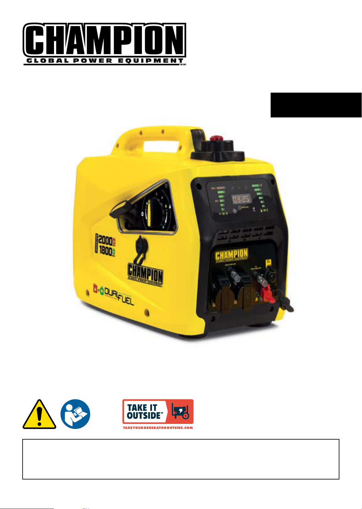
2000W Dual Fuel Inverter Generator
Patent Pending
ENGLISH
READ AND SAVE THIS MANUAL. This manual contains important safety precautions which should be read and understood before operating the product.
Failure to do so could result in serious injury. This manual should remain with the product.
Specifications, descriptions and illustrations in this manual are as accurate as known at the time of publication, but are subject to change without notice.
This product is rated in accordance with PGM A (Portable Generator Manufacturers’ Association) standard PGM A G300 (Standard for Testing and Validating
Performance of Portable Generators).
Made in China - REV 20220608 Champion Power Equipment, Inc., Santa Fe Springs, CA USA
Page 2

82001i-DF (EU)
NTRODUCTION
NTRODUCTION
Congratulations on purchasing your invertor generator. Please
follow these instructions and maintain it correctly.
THIS BOOKLET
We reserve the right to change, alter or improve the product and
this manual without prior notice.
Record the model and serial numbers as well as date and place
of purchase for future reference. Have this information available
when ordering parts and when making technical or warranty
inquiries.
CPE TECHNICAL SUPPORT TEAM
MODEL NUMBER
SERIAL NUMBER
SAFETY DEFINITIONS
The purpose of safety symbols is to attract your attention to
possible dangers. The safety symbols, and their explanations,
deserve your careful attention and understanding. The safety
warnings do not by themselves eliminate any danger. The
instructions or warnings they give are not substitutes for proper
accident prevention measures.
DANGER
DANGER indicates a hazardous situation which,if not
avoided, will result in death or serious injury.
WARNING
WARNING indicates a hazardous situation which, if not
avoided, could result in death or serious injury.
CAUTION
CAUTION indicates a hazardous situation which, if not
avoided, could result in minor or moderate injury.
DATE OF PURCHASE
PURCHASE LOCATION
NOTICE
NOTICE is used to address practices not related to physical
injury.
2
Page 3
82001i-DF (EU)
IMPORTANT SAFETY INSTRUCTIONS
IMPORTANT SAFETY INSTRUCTIONS
DANGER
Generator exhaust contains carbon monoxide, a colorless,
odorless, poison gas. Breathing carbon monoxide will cause
nausea, dizziness, fainting or death. If you start to feel dizzy
or weak, get to fresh air immediately.
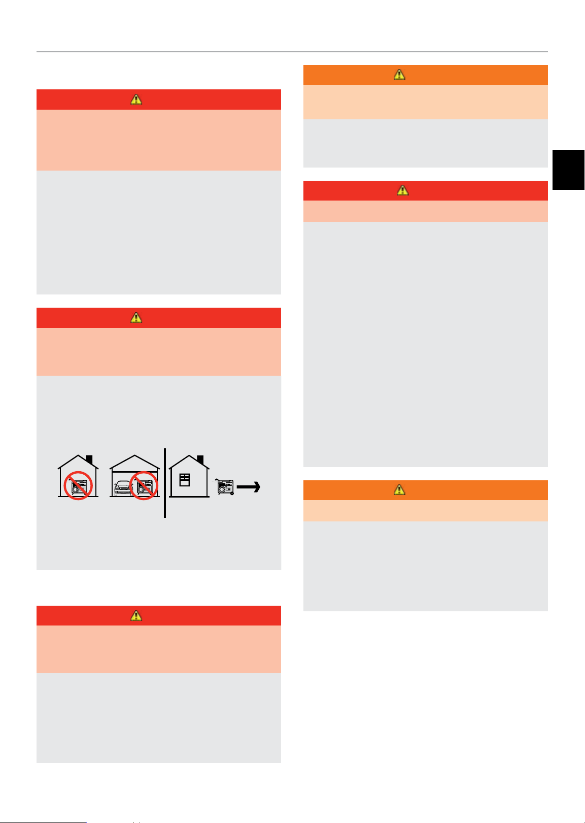
OPERATE GENERATOR OUTDOORS ONLY IN A WELL
VENTILATED AREA.
DO NOT operate the generator inside any building, including
garages, basements, crawlspaces and sheds, enclosure or
compartment, including the generator compartment of a
recreational vehicle.
DO NOT allow exhaust fumes to enter a confined area
through windows, doors, vents or other openings.
DANGER
Using a generator indoors CAN KILL YOU IN MINUTES.
Generator exhaust contains carbon monoxide. This is a
poison you cannot see or smell.
NEVER use inside a home or garage, EVEN IF doors and
windows are open.
ONLY use OUTSIDE and far away from windows, doors,
and vents.
WARNING
Operation of this equipment may create sparks that can
start fires around dry vegetation.
A spark arrestor may be required. The operator should
contact local fire agencies for laws or regulations relating to
fire prevention requirements.
EN
DANGER
Generator produces powerful voltage.
DO NOT touch bare wires or receptacles.
DO NOT use electrical cords that are worn, damaged or
frayed. Use Champion electrical cords only for proper
application.
DO NOT operate generator in wet weather.
DO NOT allow children or unqualified persons to operate or
service the generator
Use a ground fault circuit interrupter (GFCI) in damp areas
and areas containing conductive material such as metal
decking.
Connection to your home’s electrical system requires a
listed 30A transfer switch installed by a licensed electrician
and approved by the local authority having jurisdiction. The
connection must isolate the generator from the utility power
and must comply with all applicable laws and electrical
codes.
Install battery-operated carbon monoxide alarms or plug-in
carbon monoxide alarms with battery back-up according to
the manufacturer’s instructions.
DANGER
Rotating parts can entangle hands, feet, hair, clothing and/
or accessories. Traumatic amputation or severe laceration
can result.
Keep hands and feet away from rotating parts.
Tie up long hair and remove jewelry.
Operate equipment with guards in place.
DO NOT wear loose-fitting clothing, dangling drawstrings or
items that could become caught.
WARNING
Sparks can result in fire or electrical shock.
When servicing the generator:
Disconnect the spark plug wire and place it where it cannot
contact the plug or any other metal object.
DO NOT check for spark with the plug removed.
Use only approved spark plug testers.
3
Page 4

82001i-DF (EU)
IMPORTANT SAFETY INSTRUCTIONS
WARNING
Running engines produce heat. Severe burns can occur on
contact. Combustible material can catch fire on contact.
DO NOT touch hot surfaces.
Avoid contact with hot exhaust gases.
Allow equipment to cool before touching.
Maintain at least 3 ft. (91.4 cm) of clearance on all sides to
ensure adequate cooling.
Maintain at least 5 ft. (1.5 m) of clearance from combustible
materials.
WARNING
Rapid retraction of the starter cord will pull hand and arm
towards the engine faster than you can let go. Unintentional
startup can result in entanglement, traumatic amputation or
laceration. Broken bones, fractures, bruises or sprains could
result.
When starting engine, pull the starter cord slowly until
resistance is felt and then pull rapidly to avoid kickback.
DO NOT start or stop the engine with electrical devices
plugged in and turned on.
CAUTION
Improper treatment or use of the generator can damage it,
shorten its life and void your warranty.
Use the generator only for intended uses.
Operate only on level surfaces.
DO NOT expose generator to excessive moisture, dust,
or dirt.
DO NOT allow any material to block the cooling slots.
If connected devices overheat, turn them off and disconnect
them from the generator.
DO NOT use the generator if:
– Electrical output is lost
– Equipment sparks, smokes or emits flames
– Equipment vibrates excessively
WARNING
Medical and life support uses.
In case of emergency, call 911 immediately.
NEVER use this product to power life support devices or life
support appliances.
CAUTION
Exceeding the generator’s running capacity can damage the
generator and/or electrical devices connected to it.
DO NOT overload the generator.
DO NOT tamper with the governed speed.
DO NOT modify the generator in any way.
CAUTION
Start the generator and allow the engine to stabilize before
connecting electrical loads.
Connect electrical equipment in the off position, and then
turn them on for operation.
Turn electrical equipment off and disconnect before
stopping the generator.
NEVER use this product to power medical devices or
medical appliances.
Inform your electricity provider immediately if you or anyone
in your household depends on electrical equipment to live.
Inform your electrical provider immediately if a loss of power
would cause you or anyone in your household to experience
a medical emergency.
4
Page 5

82001i-DF (EU)
IMPORTANT SAFETY INSTRUCTIONS
Fuel Safety
DANGER
GASOLINE, GASOLINE VAPORS AND PROPANE (LPG) ARE
HIGHLY FLAMMABLE AND EXPLOSIVE.
Fire or explosion can cause severe burns or death.
Gasoline and gasoline vapors:
– Gasoline is highly flammable and explosive.
– Gasoline can cause a fire or explosion if ignited.
– Gasoline is a liquid fuel but it’s vapors can ignite.
– Gasoline is a skin irritant and needs to be cleaned up
immediately if spilled on skin or clothes.
– Gasoline has a distinctive odor, this will help detect potential
leaks quickly.
– In any petroleum gas fire, flames should not be extinguished
unless by doing so the fuel supply valve can be turned OFF.
This is because if a fire is extinguished and a supply of
fuel is not turned OFF, then an explosion hazard could be
created.
– Gasoline expands or contracts with ambient temperatures.
Never fill the gasoline tank to full capacity, as gasoline
needs room to expand if temperatures rise.
LPG:
– LPG is highly flammable and explosive.
– LPG is under pressure and can cause a fire or explosion if
ignited.
– LPG is heavier than air and can settle in low places while
dissipating.
– LPG has a distinctive odor added to help detect potential
leaks quickly.
DO NOT pump gasoline directly into the generator at the gas
station. Use an approved container to transfer the fuel to the
generator.
DO NOT overfill the gasoline tank.
Always keep gasoline away from sparks, open flames, pilot
lights, heat and other sources of ignition.
DO NOT light or smoke cigarettes.
EN
When starting the generator:
DO NOT attempt to start a damaged generator.
Make certain that the gasoline cap, air filter, spark plug, fuel
lines and exhaust system are properly in place.
Allow spilled gasoline to evaporate fully before attempting to
start the engine.
Make certain that the generator is resting firmly on level
ground.
When operating the generator:
DO NOT move or tip the generator during operation.
DO NOT tip the generator or allow fuel or oil to spill.
When transporting or servicing the generator:
Make certain that the fuel valve is in the OFF position and the
gasoline tank is empty.
For LPG compatible models, be sure that the LPG cylinder is
disconnected and stored securely away from the generator.
Disconnect the spark plug wire.
When storing the generator:
Store away from sparks, open flames, pilot lights, heat and
other sources of ignition.
Do not store generator, gasoline or LPG cylinders near furnaces,
water heaters, or any other appliances that produce heat or
have automatic ignitions.
– In any petroleum gas fire, flames should not be extinguished
unless the fuel supply valve is turned OFF. This is because if
a fire is extinguished and a supply of fuel is not turned OFF,
then an explosion hazard could be created.
– When exchanging LPG cylinders, be sure the cylinder valve
is of the same type.
– Always keep the LPG cylinder in an upright position.
– LPG will burn skin if it comes in contact with it. Keep any
and all LPG away from skin at all times.
When adding or removing gasoline:
Turn the generator off and let it cool for at least two minutes
before removing the gasoline cap. Loosen the cap slowly to
relieve pressure in the tank.
Only fill or drain gasoline outdoors in a well-ventilated area.
WARNING
Never use a gasoline container, gasoline tank, LPG
connector hose, LPG cylinder or any other fuel item that is
damaged or appears damaged.
5
Page 6
82001i-DF (EU)
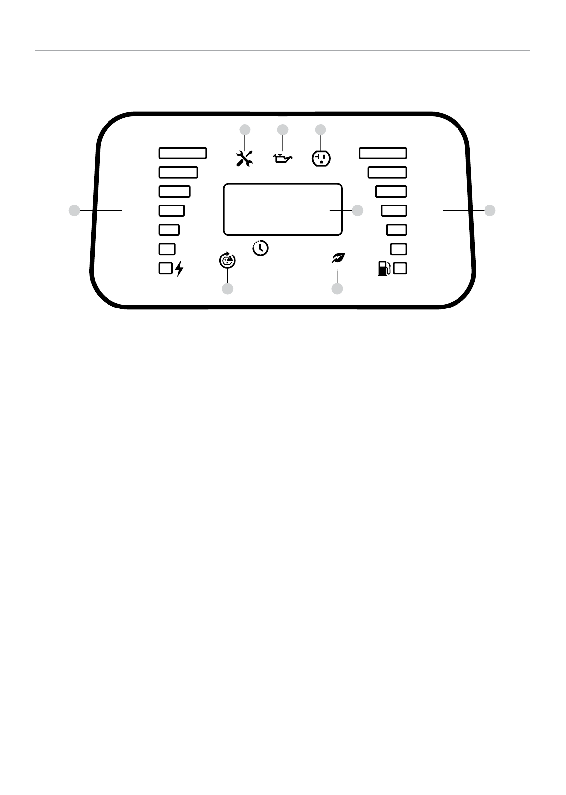
Power Panel
IMPORTANT SAFETY INSTRUCTIONS
100%
1 8
50%
0%
6 7
1. Power Output – Percentage of available power from
generator being used.
2. Maintenance Indicator
2a. Off – No service required.
2b. Yellow – Service required per Maintenance Schedule.
3. Low Oil Level Indicator
3a. Off – Oil level OK.
3b. Yellow – Oil level low. Unit will shut down or not start
until oil is at required level.
4. Receptacle Status
4a. Green – All systems OK.
4b. Red – Nearing overload but receptacle still has power.
4c. Flashing Red – Overload fault and receptacle has no
power.
2
3 4
00:00
REMA INING
5. LED Display
5a. Flashing Blue – Total run time (first 5 seconds after
5b. Amber – Remaining fuel run time or “LPG” in LPG
6. AC Overload Reset Button – Used to re-energize
receptacles after overload fault and reset maintenance
schedule.
6a. OFF – Systems normal.
6b. Yellow – Maintenance required.
6c. Blinking Red – Overload fault.
7. Economy Mode Switch – Enables/disables automatic idle
control.
7a. OFF – Economy mode OFF.
7b. Green – Economy mode ON.
5
ECO
unit started).
mode.
F
E
8. Fuel Level Indicator – Amount of fuel remaining.
6
Page 7
82001i-DF (EU)
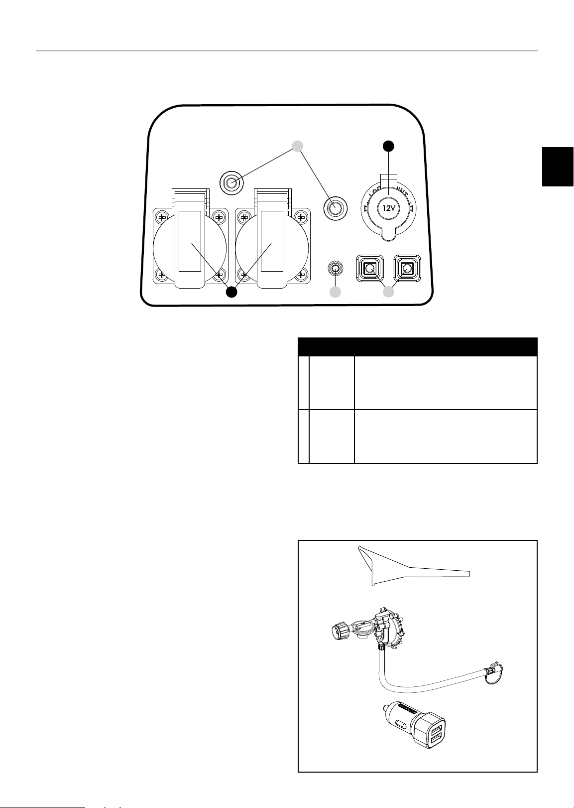
Outlet Panel
IMPORTANT SAFETY INSTRUCTIONS
B
1. Circuit Breakers (Push Reset) – Protects the generator
against electrical overloads.
2. Ground Terminal – Consult an electrician for local
grounding regulations.
3. Parallel Outlets – Used for parallel operation (parallel kit
sold separately).
1
A
EN
2
A
z
B
3
RECEPTACLES
12V DC, 8 Amp (Automotive)
May be used to supply electrical power for
operation of 12 Volt DC, 8 Amp electrical
loads.
2 x (220v 16amp) or (240v 13 amp)
May be used to supply electrical power for
operation of 220~240 Volt AC, single phase,
50 Hz electrical loads.
Parts Included
Accessories
Oil Funnel .............................................................................. 1
2.3 ft. (0.7 m) LPG Hose with Regulator ................................. 1
Dual 2.4A Port USB Adapter .................................................. 1
*Warning: Do not operate a device while it is plugged into the 12V DC outlet.
Prolonged exposure to engine exhaust can cause serious injury or death. While
charging a device do no place on the exhaust side of the generator. Extreme
heat caused by exhaust can damage the device, and cause a potential fire
hazard.
7
Page 8
82001i-DF (EU)
ASSEMBLY
This unit ships from our factory without oil. It must be properly
serviced with fuel and oil before operation.
If you have any questions regarding the assembly of your
generator, call all our your nearest Champion Distributor.
Please have your serial number and model number available.
Unpacking
1. Set the shipping carton on a solid, flat surface.
2. Remove everything from the carton except the generator.
3. Using the carrying handles of the unit, carefully remove
the generator from the box (two people lifting is
recommended).
Add Engine Oil
ASSEMBLY
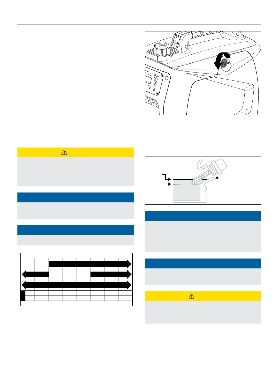
3. Remove oil fill cap/dipstick to add oil.
4. Using a funnel, add up to 0.4 qt. (0.4 L) of oil (not included)
and replace oil fill cap/dipstick. DO NOT OVERFILL.
CAUTION
DO NOT attempt to crank or start the engine before it has
been properly filled with the recommended type and amount
of oil. Damage to the generator as a result of failure to
follow these instructions will void your warranty.
NOTICE
The generator rotor has a sealed, pre-lubricated ball bearing
that requires no additional lubrication for the life of the bearing.
NOTICE
The recommended oil type is 10W-30 automotive oil.
Recommended Engine Oil Type
10W-30
10W- 405W-30
5W-30 Synthetic
5. Check engine oil level daily and add as needed.
MAX
MIN
NOTICE
Once oil has been added, a visual check should show oil
about 1-2 threads from running out of the fill hole.
If using the dipstick to check oil level, DO NOT screw in the
dipstick while checking.
NOTICE
Check oil often during the break-in period. Refer to the
Maintenance section for recommended service intervals.
OIL DIP STICK
-20 0 20 40 60
°F
-28.9
-17. 8 -6.7 4.4 15.6 26.7 37.8 48.9
°C
Ambient temperature
1. Place the generator on a flat, level surface.
2. Remove the maintenance cover.
80 100 120
CAUTION
The engine is equipped with a low oil shut-off and will stop
when the oil level in the crankcase falls below the threshold
level.
8
Page 9

82001i-DF (EU)
ASSEMBLY
NOTICE
The first 5 hours of run time are the break-in period for the
unit. During the break in period stay at or below 50% of the
running watt rating and vary the load occasionally to allow
stator windings to heat and cool. Adjusting the load will also
cause engine speed to vary and help seat piston rings. After
the 5 hour break-in period, change the oil.
NOTICE
Weather will affect engine oil and engine performance.
Change the type of engine oil used based on weather
conditions to suit the engine needs.
NOTICE
Synthetic oil may be used after the 5 hour initial breakin period. Using synthetic oil does not increase the
recommended oil change interval. Full synthetic 5W-30 oil
will aid in starting in cold ambient <5º C (41º F).
CAUTION
Use regular unleaded gasoline with a minimum octane
rating of 85 and an ethanol content of 10% or less by
volume.
DO NOT mix oil and gasoline.
Fill tank to approximately ¼ in. (6.4 mm) below the top of
the tank to allow for gasoline expansion.
DO NOT pump gasoline directly into the generator at the
pump. Use an approved container to transfer the gasoline to
the generator.
DO NOT fill tank indoors.
DO NOT fill tank when the engine is running or hot.
DO NOT overfill the tank.
DO NOT light cigarettes or smoke when filling the tank.
WARNING
Pouring gasoline too fast through the fuel screen may result
in blow back of gasoline at the operator while filling.
EN
Add Fuel: Gasoline
1. Use clean, fresh, regular unleaded gasoline with a
minimum octane rating of 85 and an ethanol content of
10% or less by volume. ybc
2. DO NOT mix oil with gasoline.
3. Remove the gasoline cap.
4. Slowly add gasoline to the tank. Tank is full when gasoline
reaches red circle on screen. DO NOT OVERFILL. Gasoline
can expand after filling. A minimum of ¼ in. (6.4 mm) of
space left in the tank is required for gasoline expansion,
although more than ¼ in. (6.4 mm) is recommended.
Gasoline can be forced out of the tank as a result of
expansion if overfilled, and can affect the stable running
condition of the generator.
5. Screw on the gasoline cap and wipe away any spilled fuel.
NOTICE
Our engines work well with 10% or less ethanol blend
gasoline. When using ethanol-gasoline blends there are
some issues worth noting:
– Ethanol-gasoline blends can absorb more water than
gasoline alone.
– These blends can eventually separate, leaving water or a
watery goo in the tank, fuel valve and carburetor.
– With gravity-fed supplies, the compromised gasoline can
be drawn into the carburetor and cause damage to the
engine and/or potential hazards.
– There are only a few suppliers of fuel stabilizer that are
formulated to work with ethanol-gasoline blends.
– Any damages or hazards caused by using improper
gasoline, improperly stored gasoline, and/or
improperly formulated stabilizers, are not covered by
manufacturer’s warranty.
It is advisable to always shut off the gasoline supply, run the
engine to starvation and drain the tank when the equipment
is not in use for more than 30 days.
9
Page 10
82001i-DF (EU)
ASSEMBLY
Add Fuel: Propane (LPG)
1. Confirm the EZ Start dial is in the OFF position.
2. If using a new propane cylinder, remove the plastic cap
from the cylinder valve.
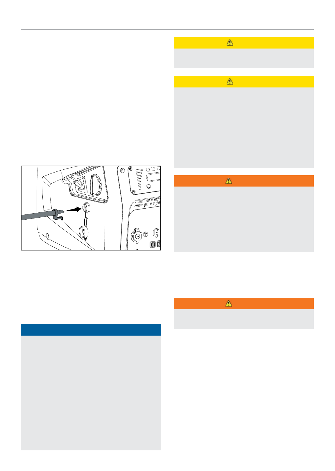
3. Attach the LPG hose assembly (included) to the propane
cylinder valve and hand tighten.
4. Remove the rubber boot covering the propane connection
port on the inverter.
5. Align the plastic finger on the male hose fitting on the
LPG hose assembly with the slot below the female quick
connect coupling on the inverter.
6. Insert the hose fitting into the quick connect coupling and
push in until you hear a “click” and the outside collar of the
quick connect coupling moves forward.
CAUTION
Do not allow children to tamper or play with the LPG cylinder
or hose connections.
CAUTION
Use approved LPG cylinders equipped with an OPD
(overfilling prevention device) valve. Always keep the
cylinder in a vertical position with the valve on top and
installed at ground level on a flat surface. Cylinders must
not be installed near any heat source and should not be
exposed to sun, rain, and dust. When transporting and
storing, turn off the cylinder valve and generator LPG valve,
and disconnect the cylinder. Plug the outlet, usually by a
plastic protective cap, if one is available. Keep cylinders
away from heat and ventilated when in a vehicle.
WARNING
If there is a strong smell of LPG: Close valve on the cylinder.
Check all connections for leaks by wetting the fittings
with a solution of soap and water. Bubbles which appear
or bubbles which grow indicate that a leak exists. Do not
smoke or light a cigarette, or check for leaks using a match,
open flame source or lighter. Contact a qualified technician
to inspect and repair an LPG system if a leak is found,
before using the generator.
7. Check all connections for leaks by wetting the fittings with
a solution of soap and water. Bubbles which appear or
bubbles which grow indicate that a leak exists. If a leak
exists at a fitting then turn off the valve on the cylinder
and tighten the fitting. Turn the valve back on and recheck
the fitting with the soap and water solution. If the leak
continues or if the leak is not at a fitting then do not use
the generator and contact customer service.
NOTICE
– The LPG hose included with this unit works with
standard 20 and 30 pound LPG tanks.
– Verify the requalification date on the cylinder has not
expired.
– All new cylinders must be purged of air and moisture
prior to filling. Used cylinders that have not been plugged
or kept closed must also be purged.
– The purging process should be done by an LPG supplier.
(cylinders from an exchange supplier should have been
purged and filled properly already).
– Always position the cylinder so the connection between
the cylinder valve and generator inlet won’t cause sharp
bends or kinks in the LPG hose.
Grounding
Your generator must be properly connected to an appropriate
ground to help prevent electric shock.
WARNING
Failure to properly ground the generator can result in
electric shock.
A ground terminal connected to the frame of the generator has
been provided (see
For remote grounding, connect of a length of heavy gauge
(12 AWG minimum) copper wire between the generator ground
terminal and a copper rod driven into the ground. We strongly
recommend that you consult with a qualified electrician to
ensure compliance with local electrical codes.
Controls and Features for terminal location).
10
Page 11
82001i-DF (EU)
OPERATION
OPERATION
Generator Location
NEVER operate the generator inside any building, including
garages, basements, crawlspaces and sheds, enclosure or
compartment, including the generator compartment of a
recreational vehicle. Please consult your local authority. In
some areas, generators must be registered with the local
utility. Generators used at construction sites may be subject
to additional rules and regulations. Generators should be on
a flat, level surface at all times. (Even while not in operation)
Generators must have at least 5 ft. (1.5 m) of clearance from
all combustible material. In addition to clearance from all
combustible material, generators must also have at least 3 ft.
(91.4 cm) of clearance on all sides to allow for adequate cooling,
maintenance and servicing. Generators should never be started
or operated in the back of a SUV, camper, trailer, in the bed of
a truck (regular, flat or otherwise), under staircases/stairwells,
next to walls or buildings, or in any other location that will not
allow for adequate cooling of the generator and/or the muffler.
DO NOT contain generators during operation. Allow generators
to properly cool before transport or storage.
Install battery-operated carbon monoxide alarms or plug-in
carbon monoxide alarms with battery back-up in your home
according to the manufacturer’s instructions.
Place the generator in a well-ventilated area. DO NOT place the
generator near vents or intakes where exhaust fumes could
be drawn into occupied or confined spaces. Carefully consider
wind and air currents when positioning generator.
Failure to follow proper safety precautions may void
manufacturer’s warranty.
WARNING
Do not operate or store the generator in rain, snow, or wet
weather.
Grounding
A ground terminal connected to the frame of the generator has
been provided (see Controls and Features for terminal location).
Neutral Floating*
– Neutral circuit IS NOT electrically connected to the frame/
ground of the generator.
– The generator (stator winding) is isolated from the frame
and from the AC receptacle ground pin.
– Electrical devices that require a grounded receptacle pin
connection will not function if the receptacle ground pin is
not functional.
Neutral Bonded to Frame*
– Neutral circuit IS electrically connected to the frame/ground
of the generator.
– The generator system ground connects lower frame
cross-member below the alternator. The system ground is
connected to the AC neutral wire.
* See your model's control panel for specified type of grounding.
Surge Protection
Electronic devices, including computers and many
programmable appliances use components that are designed
to operate within a narrow voltage range and may be affected
by momentary voltage fluctuations. While there is no way to
prevent voltage fluctuations, you can take steps to protect
sensitive electronic equipment.
– Install UL1449, CSA-listed, plug-in surge suppressors on the
outlets feeding your sensitive equipment.
Surge suppressors come in single- or multi-outlet styles.
They’re designed to protect against virtually all shortduration voltage fluctuations.
Starting the Engine: Gasoline
EN
Using a generator or electrical appliance in wet conditions,
such as rain or snow, or near a pool or sprinkler system,
or when your hands are wet, could result in electrocution.
WARNING
During operation the muffler and exhaust fumes produced
will become hot. If adequate cooling and breathing space
are not supplied, or if the generator is blocked or contained,
temperatures can become extremely heated and may lead
to fire.
1. Make certain the generator is on a flat, level surface.
2. Disconnect all electrical loads from the generator. Never
start or stop the generator with electrical devices plugged
in or turned on.
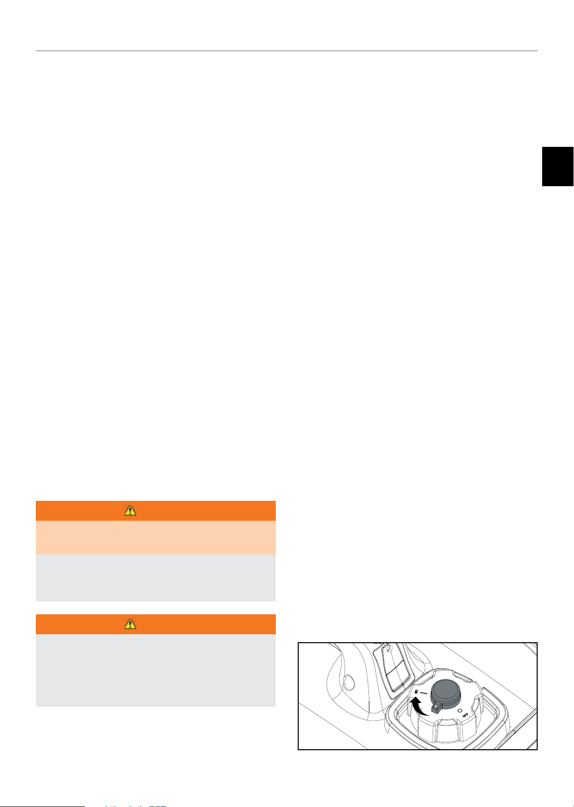
3. Turn the fuel cap vent lever to the “ON” position.
11
Page 12
82001i-DF (EU)
OPERATION
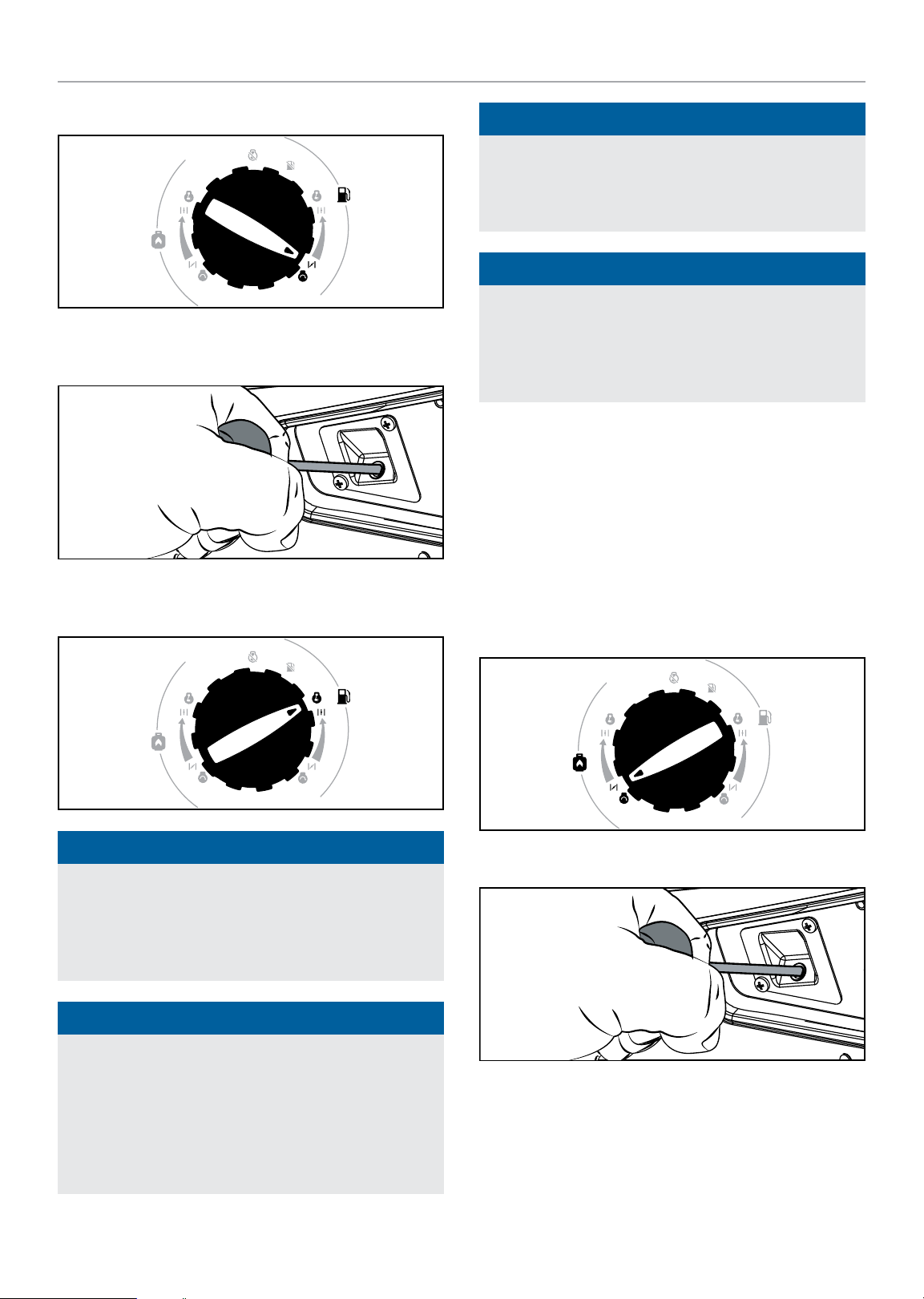
4. Turn EZ Start dial clockwise to the full CHOKE position.
-
+
-
+
5. Pull the starter cord slowly until resistance is felt and then
pull rapidly.
NOTICE
For gas starting in cold ambient <15°C (59°F): The
choke must be in 100% of the “CHOKE” position for recoil
start procedures. Do not over-choke. As soon as the engine
starts, turn the EZ Start dial to the RUN position.
NOTICE
If the engine starts but does not continue to run make
certain that the generator is on a flat, level surface. The
engine is equipped with a low oil sensor that will prevent the
engine from running when the oil level falls below a critical
threshold.
Starting the Engine: Propane (LPG)
1. Make certain the generator is on a flat, level surface.
2. Disconnect all electrical loads from the generator. Never
start or stop the generator with electrical devices plugged
in or turned on.
6. As the engine warms up, move the EZ Start dial to the RUN
position.
-
+
NOTICE
-
+
Keep EZ Start dial in “CHOKE” position for only 1 pull of
the recoil starter. If generator does not start after first pull,
rotate the EZ Start dial to the RUN position for the next
three pulls. Too much choke leads do spark plug fouling and
engine flooding. This will cause the engine not to start.
NOTICE
3. Open the fuel valve on the propane cylinder.
4. Turn EZ Start dial counterclockwise to the full CHOKE
position.
-
+
-
+
5. Slowly pull the starter cord 2-4 times to prime the engine.
For gasoline restarts with hot engine in hot ambient
> 30°C (86°F): Rotate the EZ Start dial to 75% of the
full choke position for only one pull of the recoil starter. If
generator does not start after first pull, rotate the dial to the
RUN position for the next three pulls. Too much choke leads
do spark plug fouling and engine flooding. This will cause
the engine not to start.
12
Page 13

82001i-DF (EU)
OPERATION
6. Move the EZ Start dial to the “RUN” position.
-
+
-
+
7. Pull the starter cord slowly until resistance is felt and then
pull rapidly.
NOTICE
Accumulation of frost on LPG cylinder and regulators is
common during operation and normally is not an indication
of a problem. As LPG vaporizes and travels from the cylinder
to the generator engine it expands. The amount of frost
that forms can be affected by the size of the cylinder, the
amount of LPG being used, the humidity of the air and other
operating conditions.
In unusual situations this frost may eventually restrict
the flow of LPG to the generator resulting in deteriorating
performance. For example, if the cylinder temperature is
reduced to a very low level then the rate at which the LPG
vaporizes is also reduced and may not provide sufficient
flow to the engine. This is not an indication of a problem
with the generator but only a problem with the flow of LPG
from the cylinder. If generator performance seems to be
deteriorating at the same time that ice formation is observed
on tank valve, hose or regulator then some actions may be
taken to eliminate this symptom.
In these rare situations it can be helpful to reduce or
eliminate the cold fuel system effects by doing one of the
following:
– Exchanging fuel cylinders to allow the first cylinder to
warm up, repeating as necessary.
– Placing the cylinder at the end of the generator near
the handle, where engine fan air flows out from the
generator. This air is slightly heated by flowing over the
engine. The cylinder should not be placed in the path of
the muffler outlet.
– The cylinder can be temporarily warmed by pouring
warm water over the top of the cylinder.
Connecting Electrical Loads
Let the engine stabilize and warm up for a few minutes after
starting.
Plug in and turn on the desired 220 or 240 (if applicable) Volt AC
single phase, 50 Hz electrical loads.
– DO NOT connect 3-phase loads to the generator.
– DO NOT connect 60 Hz loads to the generator.
– DO NOT overload the generator.
WARNING
Connecting a generator to your electric utility company’s
power lines or to another power source may be against
the law. In addition this action, if done incorrectly, could
damage your generator and appliances and could cause
serious injury or even death to you or a utility worker who
may be working on nearby power lines. If you plan to run a
portable electric generator during an outage, please notify
your electric utility company immediately and remember to
plug your appliances directly into the generator. Do not plug
the generator into any electric outlet in your home. Doing
so could create a connection to the utility company power
lines. You are responsible for ensuring that your generator’s
electricity does not feed back into the electric utility power
lines.
If the generator will be connected to a building electrical
system, consult your local utility company or a qualified
electrician. Connections must isolate generator power from
utility power and must comply with all applicable laws and
codes.
Do Not Overload Generator
Capacity
Follow these simple steps to calculate the running and starting
watts necessary for your purposes:
1. Select the electrical devices you plan on running at the
same time.
2. Total the running watts of these items. This is the amount
of power you need to keep your items running.
3. Identify the highest starting wattage of all devices
identified in step 1. Add this number to the number
calculated in step 2. Starting wattage is the extra burst
of power needed to start some electric driven equipment.
Following the steps listed under “Power Management” will
guarantee that only one device will be starting at a time.
EN
13
Page 14
82001i-DF (EU)
OPERATION
Power Management
Use the following formula to convert voltage and amperage to
watts:
Volts × Amps = Watts
To prolong the life of your generator and attached devices,
follow these steps to add electrical load:
1. Start the generator with no electrical load attached
2. Allow the engine to run for several minutes to stabilize.
3. Plug in and turn on the first item. It is best to attach the
item with the largest load first.
4. Allow the engine to stabilize.
5. Plug in and turn on the next item.
6. Allow the engine to stabilize.
7. Repeat steps 5-6 for each additional item.
NOTICE
Never exceed the specified capacity when adding loads to
the generator.
12V DC Automotive Style Outlet
The 12V DC outlet(s) can be used with the supplied accessories
and other commercially available 12V DC automotive style
plugs. The DC output is unregulated and can damage some
products. Confirm the input voltage range of your item is at
least 12-24V DC. When using the DC outlet turn the Eco Mode
switch to the “OFF” position.
WARNING
Do not operate a device while it is plugged in to the 12V DC
outlet.
Prolonged exposure to engine exhaust can cause serious
injury or death.
CAUTION
While charging a device do not place on the exhaust side of
the generator. Extreme heat caused by exhaust can damage
the device, and cause a potential fire hazard.
Battery Charging
Eco (Economy) Mode
The Eco Mode switch can be activated to turn on economy
control in order to minimize fuel consumption and noise while
operating the unit during times of reduced electrical output. Eco
Mode allows the engine speed to idle during periods of non-use.
The engine speed returns to normal when an electrical load is
connected. When the economy switch is off, the engine runs at
normal speed continuously.
CAUTION
For periods of high electrical load or momentary
fluctuations, the Eco Mode should be off.
1. Before connecting the battery charging cable (not included)
to a battery that is installed in a vehicle, disconnect the
vehicle battery ground cable from the negative (–) battery
terminal.
2. Plug the battery charging cable into the 12V DC receptacle
of the generator.
3. Connect the red (+) battery charger lead to the red (+)
battery terminal.
4. Connect the black (–) battery charger lead to the black (–)
battery terminal.
5. Start the generator.
Important: The 12V DC output is unregulated and may damage
other 12V DC products. When using the 12V DC outlet, turn the
Economy mode switch to the “OFF” position.
CAUTION
Do not start the vehicle while the battery charging cable is
connected and the generator is running. It will not give the
battery a boost of power. The vehicle or the generator may
be damaged. Charge only vented wet lead acid batteries.
Other types of batteries may burst, causing personal injury
or damage.
NOTICE
Be sure all electric devices including the lines and plug
connections are in good condition before connection to the
generator.
14
Page 15
82001i-DF (EU)
Parallel Operation
The Champion model 82001i-DF (EU) is parallel ready and
can be operated in parallel with another Champion unit to
increase the total available electrical power. A Champion model
100468 parallel kit (optional equipment) is required for parallel
operation.
Detailed instructions for parallel kit installation and operation
of the connected generators are provided in the parallel kit
owner’s manual.
Stopping the Engine
MAINTENANCE
-
+
-
+
EN
NOTICE
Gasoline
1. Turn off and unplug all electrical loads. Never start or stop
the generator with electrical devices plugged in or turned
on.
2. Let the generator run at no-load for several minutes to
stabilize internal temperatures of the engine and generator.
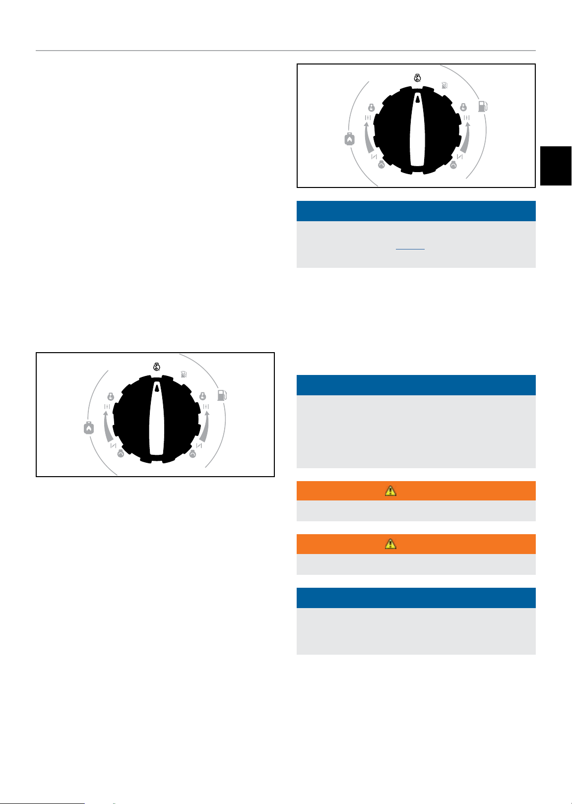
3. Turn the EZ Start dial counterclockwise to the STOP
position.
-
+
-
+
Important: Always ensure that the EZ Start dial and fuel vent
on the fuel cap are in the “OFF” position when the generator is
not in use.
If the generator will not be used for a period of two (2) weeks
or longer, please see the Storage section for proper engine
and fuel storage.
MAINTENANCE
Make certain that the generator is kept clean and stored
properly. Only operate the unit on a flat, level surface in a clean,
dry operating environment. DO NOT expose the unit to extreme
conditions, excessive dust, dirt, moisture or corrosive vapors.
NOTICE
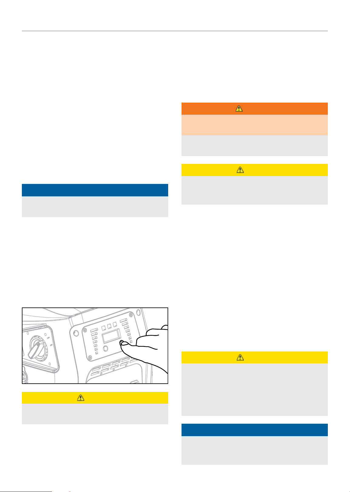
When the Maintenance Indicator light is yellow, service is
required per the Maintenance Schedule Section. To reset
the Maintenance Indicator Light, hold down the AC Overload
Reset Button for 3 seconds. (See Power Panel section under
Controls and Features.)
WARNING
Never operate a damaged or defective generator.
Propane
1. Turn off and unplug all electrical loads. Never start or stop
the generator with electrical devices plugged in or turned
on.
2. Let the generator run at no-load for several minutes to
stabilize internal temperatures of the engine and generator.
3. Close the fuel valve on the propane cylinder.
4. Turn the EZ Start dial clockwise to the STOP position.
WARNING
Improper maintenance will void your warranty.
NOTICE
Maintenance, replacement, or repair of emission control
devices and systems may be performed by any non-road
engine repair establishment or individual.
The owner/operator is responsible for all periodic maintenance.
Complete all scheduled maintenance in a timely manner.
Correct any issue before operating the generator.
15
Page 16
82001i-DF (EU)
MAINTENANCE
Cleaning the Generator
CAUTION
DO NOT spray engine with water.
Water can enter the generator through the cooling slots and
damage the generator windings. It can also contaminate the
fuel system.
1. Use a damp cloth to clean exterior surfaces of the
generator.
2. Use a soft bristle brush to remove dirt and oil.
3. Use an air compressor (25 PSI) to clear dirt and debris
from the generator.
4. Inspect all air vents and cooling slots to ensure that they
are clean and unobstructed.
To prevent accidental starting, remove the spark plug wire
before performing any service. Make sure spark plug wire end
does not rest on any metal parts.
Changing the Engine Oil
Change oil when the engine is warm. Refer to the oil
specification to select the proper grade for your operating
environment.
1. Set the generator on top of a work bench or table.
2. Remove the maintenance cover.
3. Remove the oil filler cap.
NOTICE
Once oil has been added, a visual check should show oil
about 1-2 threads from running out of the fill hole. If using
the dipstick to check oil level, DO NOT screw in the dipstick
while checking.
Cleaning and Adjusting the Spark Plug(s)
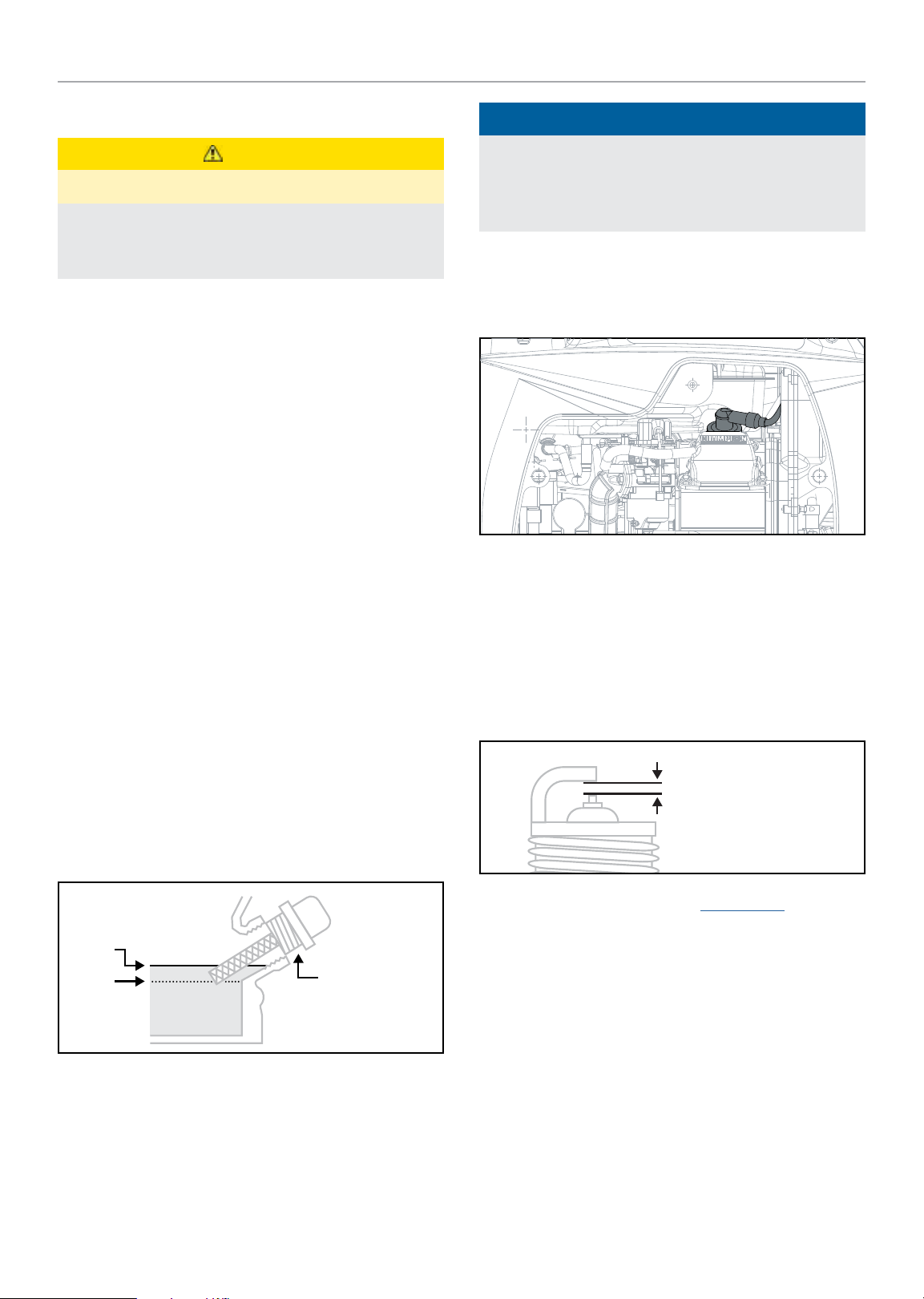
1. Remove the maintenance cover.
2. Remove the spark plug wire from the spark plug.
3. Use a spark plug socket tool (not included), or a
13/16 in. (21 mm) socket (not included) to remove the plug.
4. Inspect the electrode on the plug. It must be clean and not
worn to produce the spark required for ignition.
5. Make certain the spark plug gap is
0.024-0.028 in. (0.6-0.7 mm).
4. Tilt the generator on its side and allow the oil to drain
completely.
5. Add oil according to “Add Engine Oil” on Assembly
section. DO NOT OVERFILL. Oil not included for routine
maintenance.
MAX
MIN
6. Reinstall the maintenance cover.
7. Dispose of used oil at an approved waste management
facility.
OIL DIP STICK
SPARK PLUG GAP
6. Refer to the spark plug types in Specifications when
replacing the plug.
7. Firmly re-install the plug.
8. Attach the spark plug wire to the spark plug.
9. Reinstall the maintenance cover.
16
Page 17
82001i-DF (EU)
Cleaning the Air Filter
1. Remove the maintenance cover.
2. Locate the air filter plastic cover. Remove the screw using
a Phillips head screwdriver.
3. Remove the foam element.
4. Wash in liquid detergent and water. Squeeze thoroughly dry
in a clean cloth.
5. Saturate in clean engine oil.
6. Squeeze in a clean, absorbent cloth to remove all excess
oil.
7. Place the filter in the assembly.
8. Reattach the air filter cover.
9. Reinstall the maintenance cover and tighten the cover
screw securely.
MAINTENANCE
6. Replace the spark arrestor if it is damaged.
7. Position the spark arrestor on the muffler and attach by
reversing the steps from above.
CAUTION
Failure to clean the spark arrestor will result in degraded
engine performance.
NOTICE
Federal and local laws and administrative requirements
indicate when and where spark arrestors are required.
When ordered, spark arrestors are required for operation
of this generator in National Forest lands. In California,
this generator must not be used on any forest-covered
land, brush-covered land, or grass-covered land unless the
engine is equipped with a spark arrestor.
EN
Cleaning the Spark Arrestor
1. Allow the engine to cool completely before servicing the
spark arrestor.
2. Remove the 4 screws holding the cover plate on the
muffler side of the generator.
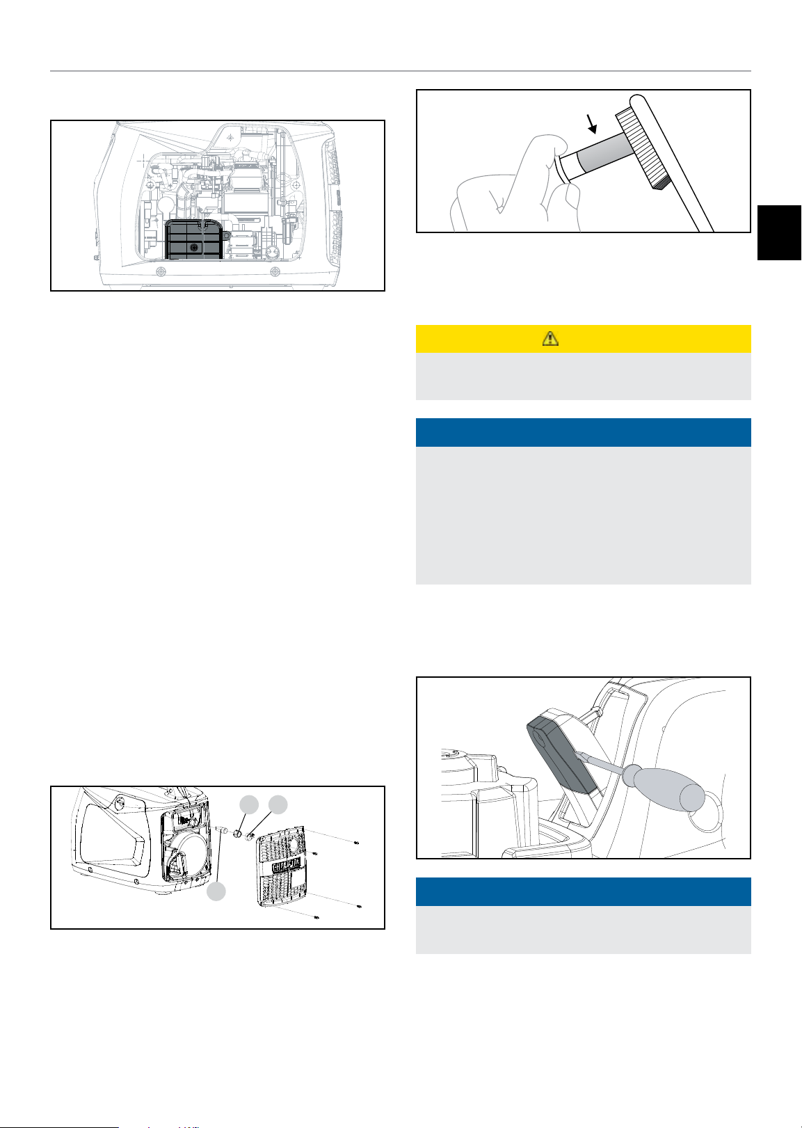
3. Remove the clamp(C) and cap(B) which retain the spark
arrestor(A) to the muffler.
B C
A
4. Remove the spark arrestor screen.
5. Carefully remove the carbon deposits from the spark
arrestor screen with a wire brush.
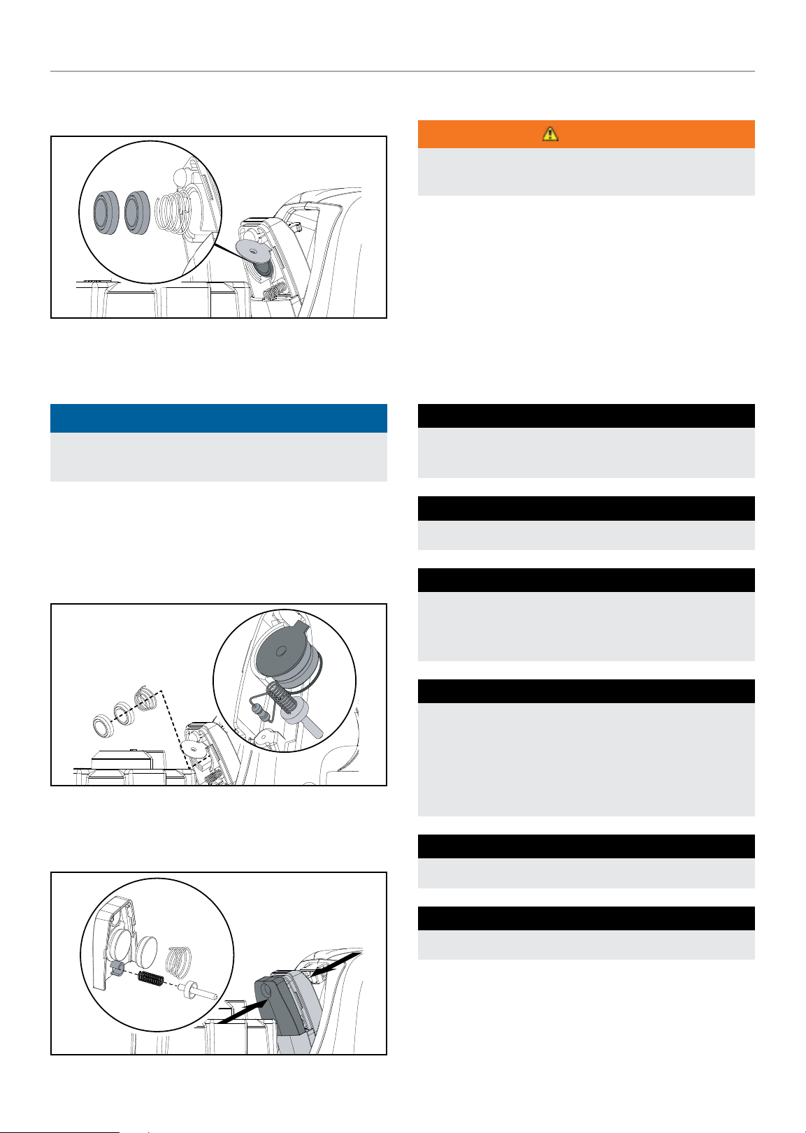
Replacing Fuel Light Batteries
1. Use a small screwdriver to disassemble the upper cover.
NOTICE
There is a notch on both sides to allow access with a
screwdriver.
17
Page 18
82001i-DF (EU)
MAINTENANCE
2. Move the round copper cover plate and remove the battery
cells.
3. Keep the small spring attached to the copper pillar and
place the compressed spring back into the bottom of the
assembly.
NOTICE
The compressed spring will have the small end facing
outward.
Adjusting the Governor
WARNING
Tampering with the factory set governor will void your
warranty.
The air-fuel mixture is not adjustable. Tampering with the
governor can damage your generator and your electrical devices
and will void your warranty.
Maintenance Schedule
Follow the service intervals indicated in the following
maintenance schedule.
Service your generator more frequently when operating in
adverse conditions.
EVERY 8 HOURS OR DAILY
Check oil level
Clean around air intake and mufer
4. Place new battery cells (2 × LR1130) back into the
assembly with negative (−) pole facing upwards and
positive (+) facing towards the compressed spring. Move
the round copper cover plate to cover and touch the button
cell.
5. Insert the small spring back into the pocket of the upper
cover and press the upper cover into place to complete the
installation.
FIRST 5 HOURS
Change oil
EVERY 50 HOURS OR EVERY SEASON
Clean air lter
Change oil if operating under heavy load or in
hot environments
EVERY 100 HOURS OR EVERY SEASON
Change oil
Clean/adjust spark plug
Check/adjust valve clearance*
Clean spark arrestor
Clean fuel tank and lter*
EVERY 250 HOURS
Clean combustion chamber*
EVERY 3 YEARS
Replace fuel line*
* To be performed by knowledgeable, experienced owners or CPE certified
service centers.
18
Page 19
82001i-DF (EU)
MAINTENANCE
STORAGE
DANGER
Gasoline and gasoline vapors are highly flammable and
extremely explosive.
Fire or explosion can cause severe burns or death. Only
fill or drain fuel outdoors in a well-ventilated area. DO NOT
pump gasoline directly into the generator. Use an approved
container to transfer the fuel to the generator. Never use
a gasoline container, gasoline tank, or any other fuel item
that is damaged or appears damaged. DO NOT overfill the
gasoline tank. Always keep fuel away from sparks, open
flames, pilot lights, heat and other sources of ignition.
DO NOT light or smoke cigarettes.
Short Term Storage (up to 1 year)
Gasoline in the gasoline tank has a maximum shelf life of up to
1 year with the addition of properly formulated fuel stabilizers
and if stored in a cool, dry place. Gasoline in the carburetor,
however, may gum up and clog the carburetor if it isn’t used or
drained within 2-4 weeks.
Long Term Storage (more than 1 year)
For storage over 1 year, the gasoline tank and carburetor must
be completely drained of gasoline.
1. Be sure all appliances are disconnected from generator.
2. Place inverter on blocks to allow appropriate gasoline
container or pan to slide under inverter.
3. Remove the maintenance cover.
4. Turn the EZ Start dial to the RUN position for gasoline.
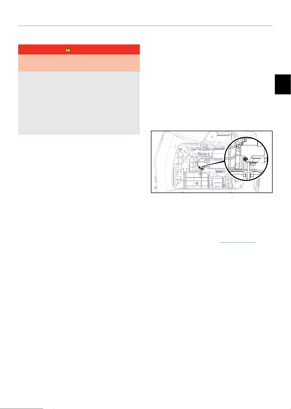
5. Using a Phillips screwdriver, rotate drain screw
counterclockwise (3) full turns. Gasoline will drain through
clear tubing out underneath the inverter. Make sure
draining gasoline empties into an appropriate container.
EN
1. Be sure all appliances are disconnected from the generator.
2. Add a properly formulated fuel stabilizer to the gasoline
tank.
3. Start engine by following directions in the “Starting the
Engine: Gasoline” section.
4. Run the generator for 10 minutes so the treated gasoline
cycles through the fuel system and carburetor.
5. Turn the EZ Start dial counterclockwise to the “RUN OUT
OF FUEL” position.
6. Let the engine run until fuel starvation has stopped the
engine. This usually takes a few minutes.
7. After the engine stops, turn the EZ Start dial
counterclockwise to the “STOP” position.
8. Allow the engine to cool.
9. Remove maintenance cover.
10. Remove the spark plug and pour about a tablespoon of oil
into the cylinder.
11. SLOWLY pull the recoil to rotate the engine to distribute
and lubricate the cylinder.
6. When gasoline stops flowing from the clear tube, rotate
drain screw clockwise until tight. Properly dispose of
the drained gasoline according to local regulations or
guidelines.
7. Turn the EZ Start dial to the STOP position.
8. Follow steps 8-12 according to Short Term Storage.
12. Re-install the spark plug and spark plug wire.
13. Re-install the maintenance cover.
14. Clean the generator according to Cleaning the Generator.
15. Store the generator in a cool, dry place out of direct
sunlight.
19
Page 20

82001i-DF (EU)
Removing from Storage
If the generator has been improperly stored for a long period
of time with gasoline in the gasoline tank and/or carburetor, all
fuel must be drained and the carburetor must be thoroughly
cleaned. This process involves technically advanced tasks. For
assistance please call your nearest Champion distributor.
If the gasoline tank and carburetor were properly emptied of all
gasoline prior to the generator being stored, follow the below
steps when removing from storage.
1. Be sure the EZ Start dial is in the STOP position.
2. Add gasoline to the generator according to Add Fuel:
Gasoline.
3. Move the EZ Start dial to the START position.
4. After 5 minutes check the carburetor and air filter areas for
any leaking gasoline. If any leaks are found, the carburetor
will need to be disassembled and cleaned or replaced. If
no gasoline leaks are found, turn the EZ Start dial to the
“STOP” position.
MAINTENANCE
5. Check engine oil level and add clean, fresh oil if needed.
See Oil Specifications for proper oil type.
6. Check and clear air filter of any obstructions such as bugs
or cobwebs. If necessary, clean air filter according to
Cleaning the Air Filter.
7. Start the generator according to Starting the Engine.
DANGER
Generator exhaust contains odorless and colorless carbon
monoxide gas.
To avoid accidental or unintended ignition of your generator
during periods of storage, the following precautions should
be followed:
– When storing the generator make sure the EZ Start dial
is set to the “OFF” position.
20
Page 21
82001i-DF (EU)
SPECIFICATIONS
SPECIFICATIONS
Generator Specifications
Generator Model ................................ 82001i-DF (EU)
Star t Type ................................................ Manual
Watts (Starting/Running) ........................... 2000/1600
Watts (LPG) (Starting/Running) ...................... 1800/14 40
AC Volts .................................................. 220/240
AC Amps @ 120V ......................................... 7/6.6 6
DC Volts ........................................................12
DC Amps ......................................................... 8
Frequency .................................................. 50 Hz
Phase .......................................................Single
Gross Weight .................................. 57.5 lb. (26.1 kg)
Net Weight ...................................... 48.7 lb. (22.1 kg)
Length ........................................... 20.5 in. (52 cm)
Width ......................................... 12.8 in. (32.5 cm)
Height ............................................ 16.9 in. (43 cm)
Fuel Specifications
Use regular unleaded gasoline with a minimum octane rating of
85 and an ethanol content of 10% or less by volume. DO NOT
USE E15 or E85. DO NOT OVERFILL.
Gasoline Capacity .................................1.1 gal. (4.2 L)
Spark Plug Specifications
OE M Type ........................................... NHSP E7RTC
Replacement Type ...................NGK BPR7HS or equivalent
Gap ...............................0.024-0.028 in. (0.6-0.7 mm)
Valve Specifications
Intake Clearance ............................. 0.004 in. (0.1 mm)
Exhaust Clearance ........................... 0.004 in. (0.1 mm)
NOTICE
A technical bulletin regarding valve adjustment procedures
is available at www.championpowerequipment.com.
EN
Engine Specifications
Model ..............................................YF149FD-L_G
Displacement ............................................... 80 cc
Type ................................................ 4-Stroke OHV
Oil Specifications
DO NOT OVERFILL.
Type ............................................ *See chart below
Capacity ........................................... 0.4 qt. (0.4 L)
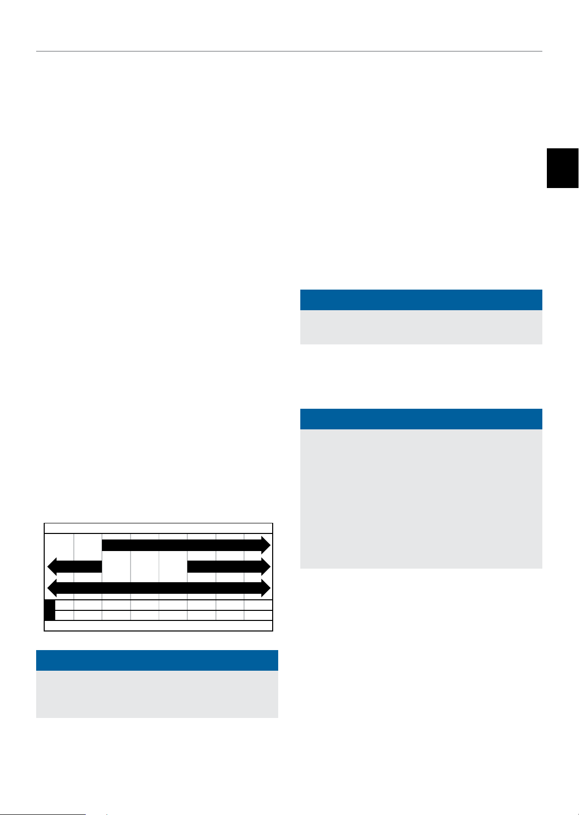
Recommended Engine Oil Type
10W-30
10W- 405W-30
5W-30 Synthetic
-20 0 20 40 60
°F
-17. 8 -6.7 4.4 15.6 26.7 37. 8 48.9
°C
-28.9
Ambient temperature
NOTICE
80 10 0 120
Temperature Specifications
Starting Temperature Range (°F/°C) ........ 5 to 104/-15 to 40
NOTICE
An important message about temperature: Your product
is designed and rated for continuous operation at ambient
temperatures up to 40°C (104°F). When your product is
needed it may be operated at temperatures ranging from
5°F (-15°C) to 122°F (50°C) for short periods of time. If
exposed to temperatures outside this range during storage,
it should be brought back within this range before operation.
In any event, the product must always be operated
outdoors, in a well-ventilated area and away from doors,
windows and vents.
Weather will affect engine oil and engine performance.
Change the type of engine oil used based on weather
conditions to suit the engine needs.
21
Page 22
82001i-DF (EU)
TROUBLESHOOTING
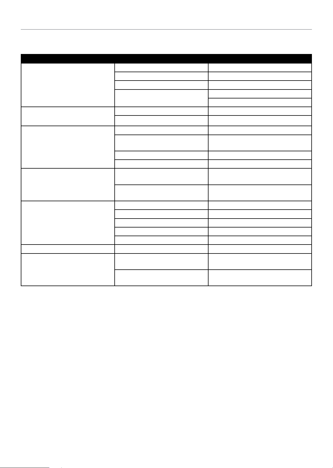
Problem Cause Solution
No fuel. Add fuel.
Faulty spark plug. Replace spark plug.
Generator will not start.
Generator will not start;
Generator starts but runs roughly.
Generator shuts down during operation.
Generator cannot supply enough power
or overheating.
No AC output.
Generator gallops. Engine governor defective. Contact the help line.
Repeated circuit breaker tripping.
Unit loaded during start up. Remove load from unit.
Low oil level.
Choke in the wrong position. Adjust choke.
Spark plug wire loose. Attach wire to spark plug.
Out of fuel. Fill fuel tank.
Low oil level.
Overload condition Remove load, press reset button
Overheat condition Let generator cool down
Generator is overloaded.
Insufficient ventilation.
Cable not properly connected. Check all connections.
Connected device is defective. Replace defective device.
Circuit breaker is open. Reset circuit breaker
Loose wiring. Inspect and tighten wiring connections.
Other. Contact the help line.
Overload.
Faulty cords or device.
Fill crankcase to the proper level.
Place generator on a flat, level surface.
Fill crankcase to the proper level. Place
generator on a flat, level surface.
Review load and adjust. See “Connecting
Electrical Loads.”
Check for air restriction. Move to a well
ventilated area.
Review load and adjust. See "Connecting
Electrical Loads."
Check for damaged, bare or frayed wires.
Replace defective device.
TROUBLESHOOTING
22
Page 23

82001i-DF (EU)
WARRANTY*
WARRANTY*
CHAMPION POWER EQUIPMENT
3 YEAR LIMITED WARRANTY
Warranty Qualifications
To register your product for warranty and FREE lifetime call
center technical support please visit:
https://www.championpowerequipment.co.uk
To complete registration you will need to include a copy of
the purchase receipt as proof of original purchase. Proof of
purchase is required for warranty service. Please register within
ten (10) days from date of purchase.
Repair/Replacement Warranty
CPE warrants to the original purchaser that the mechanical
and electrical components will be free of defects in material
and workmanship for a period of three (3) years for domestic
usage or 1000 hours which comes first and One (1) Year for
commercial and industrial use or 1000 hours which ever comes
first. Transportation charges on product submitted for repair
or replacement under this warranty are the sole responsibility
of the purchaser. This warranty only applies to the original
purchaser and is not transferable. For full T&C’s please visit
www.championpowerequipment.co.uk.
Do Not Return The Unit To The Place Of
Purchase
Contact CPE’s Technical Service and CPE will troubleshoot any
issue via phone or e-mail. If the problem is not corrected by
this method, CPE will, at its option, authorize evaluation, repair
or replacement of the defective part or component at a CPE
Service Center. CPE will provide you with a case number for
warranty service. Please keep it for future reference. Repairs or
replacements without prior authorization, or at an unauthorized
repair facility, will not be covered by this warranty.
Warranty Exclusions
This warranty does not cover the following repairs and
equipment:
Normal Wear
Products with mechanical and electrical components need
periodic parts and service to perform well. This warranty does
not cover repair when normal use has exhausted the life of a
part or the equipment as a whole.
Installation, Use and Maintenance
This warranty will not apply to parts and/or labor if the product
is deemed to have been misused, neglected, involved in an
accident, abused, loaded beyond the product’s limits, modified,
installed improperly or connected incorrectly to any electrical
component. Normal maintenance is not covered by this
warranty and is not required to be performed at a facility or by a
person authorized by CPE.
Other Exclusions
This warranty excludes:
– Cosmetic defects such as paint, decals, etc.
– Wear items such as filter elements, o-rings, etc.
EN
– Accessory parts such as starting batteries, piston rings and
storage covers.
– Failures due to acts of God and other force majeure events
beyond the manufacturer’s control.
– Problems caused by parts that are not original Champion
Power Equipment parts.
Any part(s) deemed to be damaged by the user.When applicable,
this warranty does not apply to products used for prime power
in place of a utility.
Limits of Implied Warranty and
Consequential Damage
Champion Power Equipment disclaims any obligation to
cover any loss of time, use of this product, freight, or any
incidental or consequential claim by anyone from using this
product. THIS WARRANTY AND THE ATTACHED UK EPA and/
or CARB EMISSION CONTROL SYSTEM WARRANTIES (WHEN
APPLICABLE) ARE IN LIEU OF ALL OTHER WARRANTIES,
EXPRESS OR IMPLIED, INCLUDING WARRANTIES OF
MERCHANTABILITY OR FITNESS FOR A PARTICULAR PURPOSE.
A unit provided as an exchange will be subject to the warranty
of the original unit. The length of the warranty governing the
exchanged unit will remain calculated by reference to the
purchase date of the original unit.
This warranty gives you certain legal rights which may change
from state to state or province to province. Your state or
province may also have other rights you may be entitled to that
are not listed within this warranty.
23
Page 24
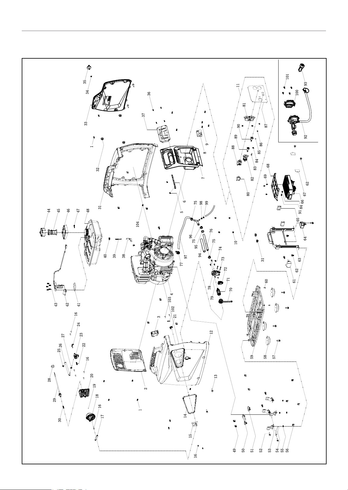
82001i-DF (EU)
Parts Diagram
WARRANTY*
35
34
33
1
32
31
48
47
46
45
44
38
39
40
41
42
43
16
24
27
26
25
23
22
16
104
36
37
9
8
7
6
75
99
98
5
96
97
77
4
103
102
3
21
76
75
75
95
94
78
79
12
11
81
90
89
88
10
74
73
72
71
70
87
86
85
84
68
83
69
82
80
31
60
58
59
101
9392
100
62
67
66
84
91
65
64
63
62
61
57
28
29
30
20
19
18
16
17
2
1
14
15
16
13
50
49
53
51
54
52
56
55
24
Page 25
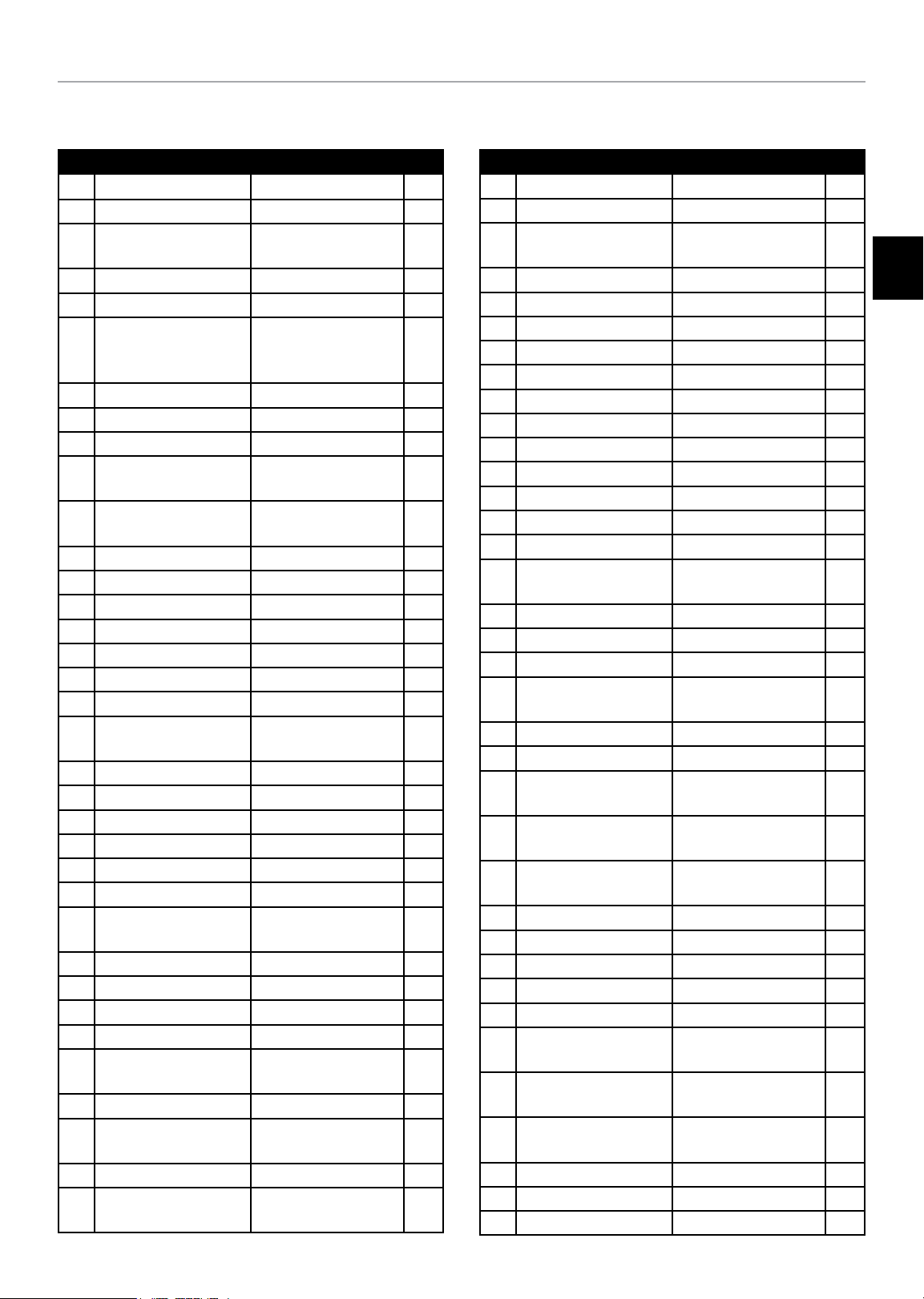
82001i-DF (EU)
Parts List
WARRANTY*
# Part Number Description Qty.
1 1.818.0514.3
2 62.200200.00 Cover, Left, black 1
3 62.214000.00
4 62.490 Engine, 80 cc 1
5 2.03.061 Circlip 2
6 62.214000.01
7 62.200300.00 Cover, Right, black 1
8 88.126000.00 Ignition Assembly 1
9 1.818.0414.3 Screw M4 × 14 2
10 1.6177.1.04.1
11 100306.21
12 62.200101.01.48 Front Cover, Yellow 1
13 1.5789.0615.3 Flange Bolt M6 × 15 4
14 62.200106.00 Protection Strip 1
15 62.061200.00 Guide Plate, Rope 1
16 1.823.0412.3 Screw M4 × 12 9
17 62.139002.00 Cover, Rotary Knob 1
18 62.139001.01 Rotary Knob 1
19 62.139008.00
20 62.139004.01 Fixed Plate 1
21 5.1050.008 Microswitch 1
22 62.139007.00 Spring, Steel Ball 1
23 62.070400.01 Fuel Valve 1
24 62.139006.00 Pressure Plate 1
25 2.06.016 Clamp, Ø8.7 × b8 2
26 62.070011.00
27 2.06.007 Clamp, Ø8 × b6 1
28 2.02.036 Thin Hexnut M16 × 1.5 1
29 62.130200.00 Pull Choke Assembly 1
30 62.130201.00 Spring, Pull Choke 1
31 62.200401.00.48
32 81.200102.00 Rotundity Jacket 3
33 62.200402.01.48
34 1.896.0 5 Split Washer Ø5 1
35 62.200410.00
Screw M5 × 14, Green
Indicator Light
Assembly, Fuel Tank
Indicator Light
Assembly,
Control Panel
Lock Nut M4, Flange,
Green
Control Panel
Assembly
Ball Bearing,
Rotary Knob
Pipe, Fuel Valve to
Carburetor
Supporter, Rear Cover,
Yellow
Protector, Rear Cover,
Yellow
Rotary Knob, Protector,
Rear Cover
12
# Part Number Description Qty.
36 1.819.0414.2 Sunk Screw M4 × 14 4
37 62.210017.00 Multifunction Display 1
1
1
6
1
1
1
1
1
1
38 88.070011.01
39 111.070 30 0.01 Fuel Filter, Wire Mesh 1
40 2.06.018 Clamp, Ø10.5 × b8 1
41 122.070036.00 Seal Ring 1
42 62.070035.00 Fuel Level Sensor 1
43 1.819.0516. 2 Sunk Screw M5 × 16 5
44 62.070100.00 Fuel Tank Cap 1
45 62.070300.00 Fuel Filter 1
46 62.200502.00 Spillway, Fuel Tank 1
47 82.080009.00 Mustache clip 1
48 62.071000.00 Fuel Tank, 4.2L, Black 1
49 2.02.010 Cage Nut M5 10
50 81.200603.00 Mount, End Cover 1
51 81.200602.00
52 1.5789.0615 Flange Bolt M6 × 15 6
53 81.200605.00 Motor Mount 4
54 2.05.050 Clamp, Wire, 100 1
55 1.6177.1.06.3
56 2.02.013 Cage Nut M6 4
57 1.5789.0620 Flange Bolt M6 × 20 4
58 62.200604.00
59 62.200601.00
60 1.845.2913
61 5.1800.003 Rectifier 1
62 1.5789.0612 Flange Bolt M6 × 12 5
63 62.070045.01 Supportor, Fuel Tank 1
64 5.1820.00 4 Charger 1
65 81.220001.00 Protector, Control Unit 2
66 62.221000.00
67 81.220003.00
68 62.220006.00
69 1.9 074.1.0408 Screw M4×8 3
70 62.200102.00 Circular Rubber Sheath 1
71 87.070021.02 Inlet Connection 1
Pipe,
Fuel Tank to Valve
Mounting Rubber,
End Cover
Lock Nut M6, Flange,
Green
Mounting Rubber,
Base Setting
Base Setting
Component
Tapping Screw
ST2.9 × 13
Control Unit,
1600W / 120V / 60HZ
Pressure Plate,
Control Unit
Air Shroud,
Control Unit
1
EN
1
4
4
1
2
1
2
1
25
Page 26
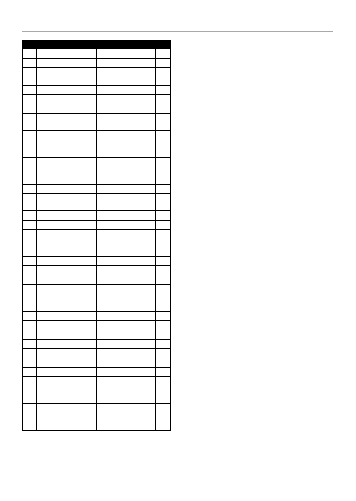
82001i-DF (EU)
# Part Number Description Qty.
72 5.1050.000 Microswitch 1
73 1.819.1.0330 Sunk Screw M3 × 30 2
74 1.845.3513
75 2.06.048 Clamp Ø15.7 3
76 62.070012.00 Pipe 220 mm 1
77 2.06.019 Hose Clamp Ø15 1
78 62.070037.00
79 1.6170.03 Hexagon Nut M3 2
80 5.1200.308
81 5.1120.010
82 5.1110.0 05 Receptacle, DC12V 1
83 1.5783.0516.3 Bolt M5 × 16, Green 1
84 1.862.05
85 1.97.1.05.3 Washer, Ø5, Green 1
86 1.6170.05.3 Nut M5, Green 2
87 62.01.1.2 Control Panel 1
88 5.1213.920
89 83.210001.00.1 Connect Port, Black 1
90 83.210001.00.3 Connect Port, Red 1
91 1.16 674 .0510 Flange Bolt M5 × 10 1
92 62.130000.90
93 9.1700.008 Plug, USB 5V/2.4A 1
94 5.1320.02 9 Plastic Pipe 170 mm 1
95 2.12.011 Buffer Ring Ø15 × 9 1
96 62.130 031.00 Three Way Pipe 1
97 62.070012.01 Pipe 150 mm 1
98 2.06.049 Clamp Ø10.5 1
99 2.12.004 Buffer Ring Ø9.5 × 10 1
100 62.138000.90 Regulator Cover 1
101 1.5789.0612.1
102 62.200025.00 Pressure Plate 1
103 1.848.2995
104 1.818.0512.3 Screw M5 x 12, Green 2
Tapping Screw
ST3.5 × 13
Support, Inlet
Connection
8Amp Circuit Breaker,
Push Button
Receptacle 5-20R,
Duplex
Lock Washer Ø5,
Toothed
20Amp Circuit Breaker,
Push Button, CSA
LPG Hose With
Regulator, 700 mm
Flange Bolt M6 × 12,
black
Tapping Screw
ST2.9 × 9.5
WARRANTY*
4
1
1
1
2
1
1
4
2
26
Page 27
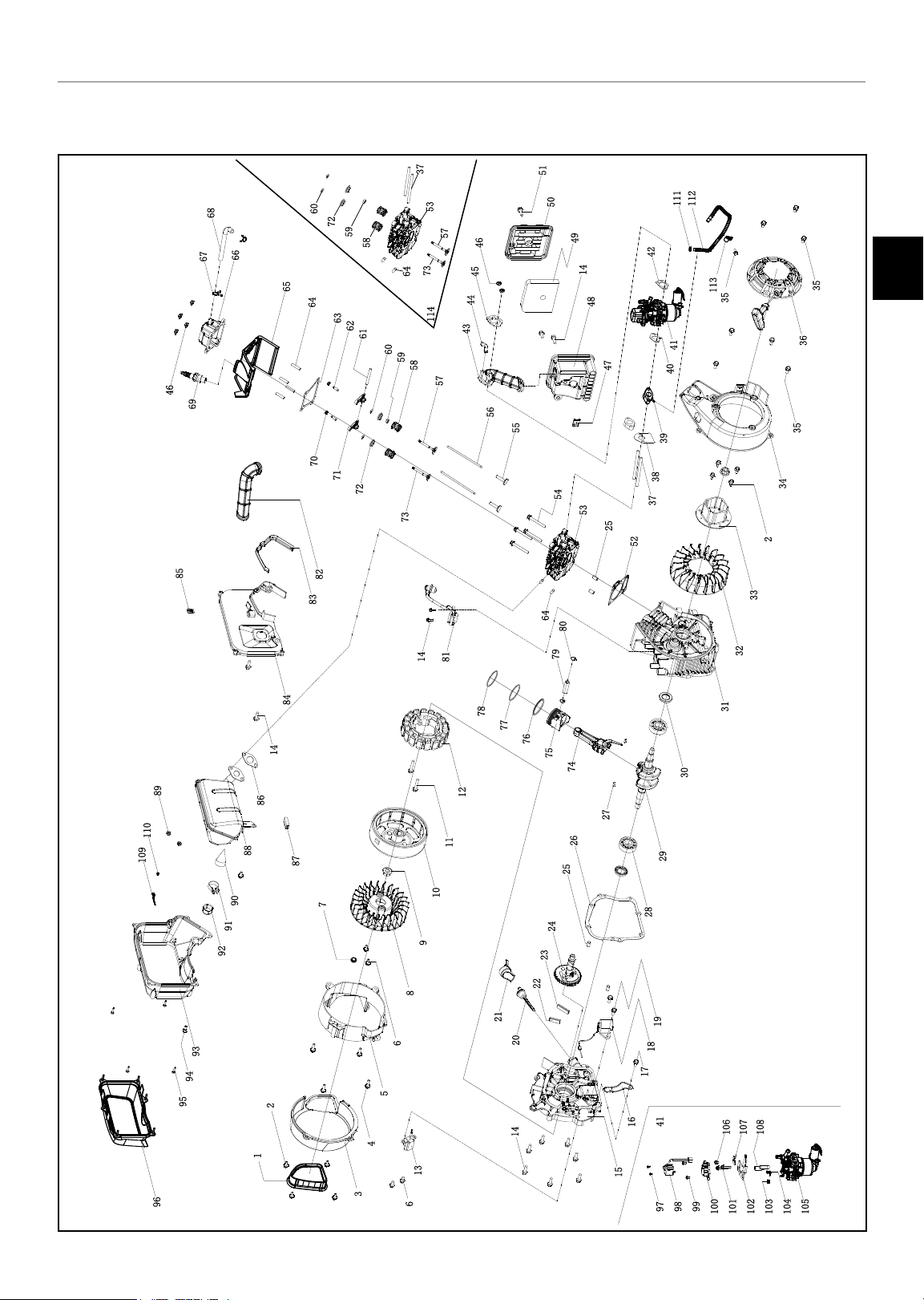
82001i-DF (EU)
Engine Parts Diagram
WARRANTY*
37
68
66
67
46
69
85
60
72
59
58
65
64
63
62
61
70
71
72
82
83
53
57
46
73
64
60
59
58
73
14
45
44
114
43
57
56
81
51
111
50
49
14
48
47
55
54
53
25
52
64
80
79
112
42
EN
113
35
41
40
39
38
37
33
32
35
36
35
34
2
109
84
14
89
110
93
94
95
96
86
88
90
91
92
87
7
9
8
6
2
1
5
4
13
3
6
78
77
76
75
74
12
27
11
10
21
20
14
26
25
24
23
22
29
28
19
18
17
41
16
15
979899
31
30
106
107
108
100
101
102
103
104
105
27
Page 28
82001i-DF (EU)
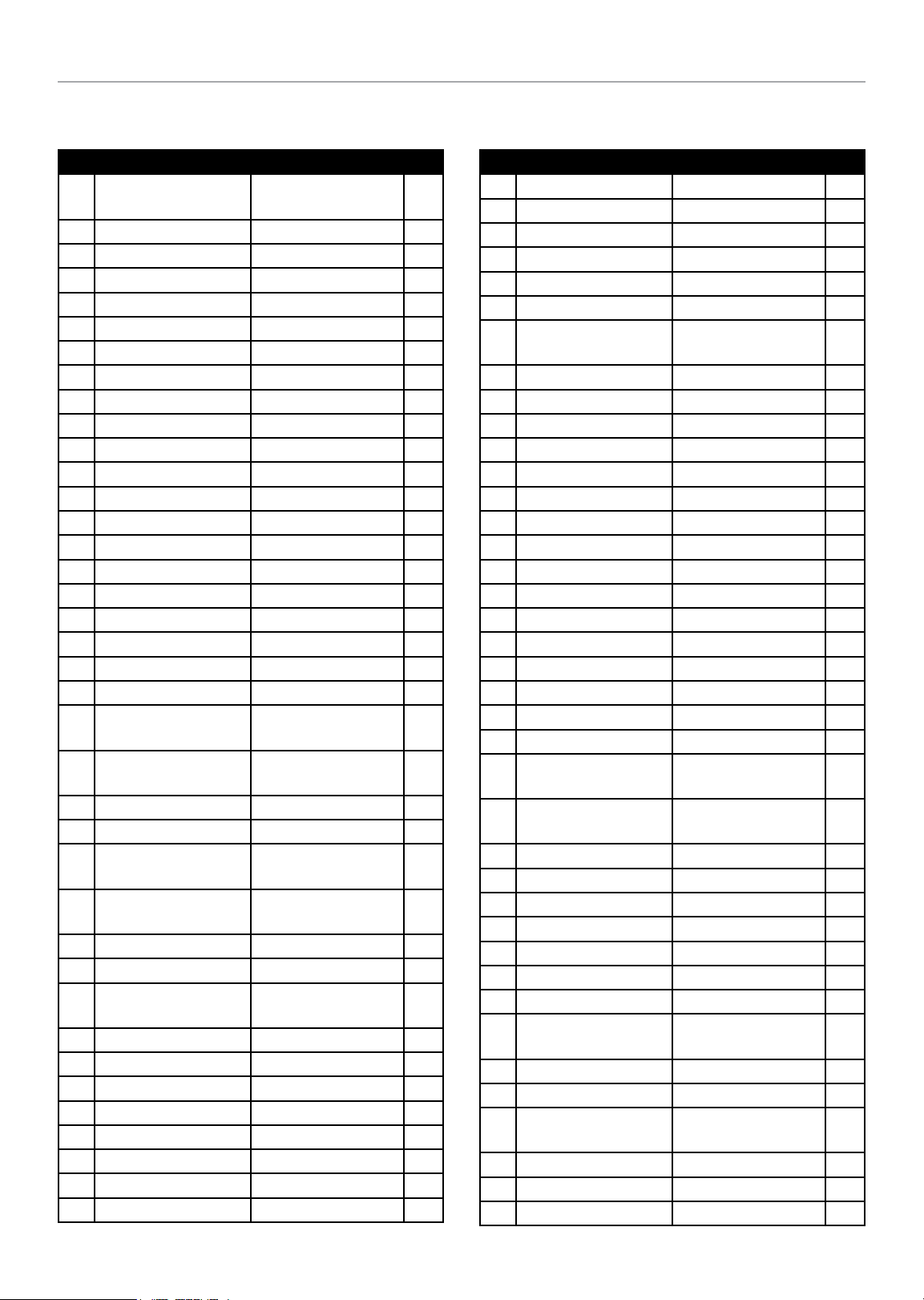
Engine Parts List
WARRANTY*
# Part Number Description Qty.
1 62.190006.00
2 1.5789.0512 Flange Bolt M5 × 12 4
3 62.190002.01 Cover, End Housing 1
4 1.16 674 .062 0 Flange Bolt M6 × 20 4
5 62.190002.00 End Housing, Motor 1
6 1.16674.0612 Flange Bolt M6 × 12 5
7 24.091008.01 End Cap 1
8 62.190001.00 Cooling Fan, Rotor 1
9 2.02.018 Nut M12 × 1.25 2
10 62.191100.00 Rotor Component 1
11 1.5789.0635 Flange Bolt M6 × 35 2
12 62.19 120 0.0 3 Stator Component 1
13 81.122000.00 Trigger Assembly 1
14 1.5789.0620 Flange Bolt M6 × 20 12
15 81.030007.00 Cover, Crankcase 1
16 81.030006.00 Plate, Coil 1
17 1.5789.0608 Flange Bolt M6 × 8 1
18 81.127000.00 Oil Level Sensor 1
19 1.5789.0612 Flange Bolt M6 × 12 2
20 81.031000.00 Oil Dipstick Assembly 1
21 81.030035.00 Oil Nipple 1
22 81.030013.00
23 81.030013.01
24 81.040100.00 Camshaft 1
25 2.04.002 Dowel Pin Ø8 × 14 4
26 81.030008.00
27 2.14.013
28 1.276.6204 Bearing 6204 2
29 81.050100.00 Crankshaft 1
30 2.11.019
31 81.030100.00 Crankcase 1
32 81.080001.00 Cooling Fan 1
33 81.060001.00 Pulley, Starter 1
34 62.080100.00 Fan Cover 1
35 1.5789.0615 Flange Bolt M6 × 15 9
36 62.061000.00 Recoil Assembly 1
37 2.01.049 Stud Bolt M6 × 99 2
38 81.130002.00 Gasket, Insulator 1
Rubber Sleeve,
End Cover
Seal Strip 1,
Crankcase Cover
Seal Strip 2,
Crankcase Cover
Gasket,
Crankcase Cover
Woodruff Key
3 × 5 × 13
Oil Seal
Ø20 × Ø35 × 5
# Part Number Description Qty.
1
1
1
1
2
2
39 62.130001.00 Insulator, Carburetor 1
40 81.130003.00 Gasket, Carburetor 1
41 62.130000.03 Carburetor Assembly 1
42 81.130004.00 Gasket, Air Cleaner 1
43 81.090004.00 Pipe, Air Cleaner 1
44 81.090003.00 Joint, Breather Pipe 1
45 81.090005.00
46 1.6177.1.06.3 Flange Lock Nut M6 6
47 2.02.013 Cage Nut M6 1
48 62.091100.00 Base, Air Cleaner 1
49 81.091003.00 Element, Air Cleaner 1
50 62.091200.00 Cover, Air Cleaner 1
51 2.08.053 Bolt M6 × 20 1
52 81.030009.00 Gasket, Cylinder Head 1
53 62.010100.02 Cylinder Head 1
54 1.5789.0655 Flange Bolt M6 × 55 4
55 81.040013.00 Lifter, Valve 2
56 81.040005.00 Push Rod 2
57 81.040002.00 Valve, Intake 1
58 83.040003.01 Spring, Valve 2
59 81.040017.00 Oil Seal, Valve 1
60 83.040014.01 Valve Collet 2
61 81.040016.00 Shaft, Rocker Arm 1
62 81.040012.00
63 62.020002.00
64 2.01.027 Stud Bolt M6 × 27 6
65 62.080200.00 Air Shroud, Cylinder 1
66 62.021000.00 Cover, Cylinder Head 1
67 2.06.010 Clamp, Ø10.5 × Ø1 2
68 62.020001.00 Breather Tube 1
69 2.15.013 Spark Plug E7RTC 1
70 2.02.009 Nut M5 × 0.5, Lock 2
71 81.040009.00
72 83.040001.01 Retainer, Valve Spring 2
73 81.040006.00 Valve, Exhaust 1
74 81.050200.00
75 81.050005.02.1 Piston 1
76 81.050303.02 Ring Assembly, Oil 1
77 81.050302.02 Piston Ring, Second 1
Pressure Plate,
Air Filter Tube
Screw,
Valve Adjustment
Gasket,
Cylinder Head Cover
Rocker Arm,
Intake Valve
Connecting Rod
Assembly
1
2
1
2
1
28
Page 29
82001i-DF (EU)
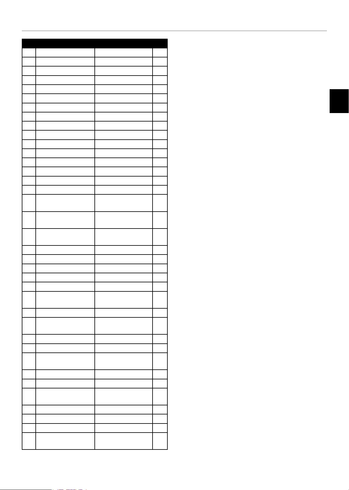
# Part Number Description Qty.
78 81.050301.02 Piston Ring, First 1
79 81.050003.00 Wrist Pin, Piston 1
80 2.09.007 Circlip Ø13.5 × Ø1 2
81 81.123000.01 Ignition Coil 1
82 81.080003.00 Air Duct 1
83 81.0810 01.00 Muffler Protector Seal 1
84 62.081100.00 Muffler Protector, Side 1
85 81.081003.00 Fastening Insert Piece 1
86 81.100001.00 Gasket, Exhaust Pipe 1
87 81.081002.00 Rubber Seal Sleeve 1
88 62.101100.00 Muffler Assembly 1
89 1.6175.06.3 Nut M6 2
90 81.10130 0.00 Spark Arrester 1
91 2.06.011 Clamp, Ø25 × b10 1
92 81.101501.00 Cap, Spark Arrester 1
93 62.081200.00 Middle Shield, Muffler 1
94 1.70.0616
95 1.845.4817
96 62.081300.00
97 1.818 .030 6.1 Screw M3 × 6 2
98 62.132200.00 Stepper Motor 1
99 1.9074.1.0408 Screw M4 × 8 2
100 81.13210 0.00 Stepper Motor Base 1
101 1.9074.4.0535 Screw M5 × 35 2
102 62.130005.00
103 81.130010.00 Spring, Connecter 1
104 81.130008.00
105 81.131000.03 Carburetor 1
106 1.9074.3.0510 Screw M5 × 10 1
107 62.130007.00
108 81.130006.00 Brace, Support Plate 2
109 62.080005.00 Plate, Middle Shield 1
110 1.8 45.4295
111 2.06.049 Clip Ø10.5 1
112 62.070012.02 Pipe 315 mm 1
113 2.05.055 Clamp Ø9.5 1
114 62.010000.00
Inside Hexagonal Bolt
M6 × 16
Tapping Screw
ST4.8 × 17
Terminal Shield,
Muffler
Support,
Stepper Motor
Connecter,
Choke Valve Axis
Pressure Plate,
Choke Control Line
Tapping Screw
ST4.2 × 9.5
Cylinder Head
Assembly
WARRANTY*
EN
1
4
1
1
1
1
1
1
29
Page 30
82001i-DF (EU)
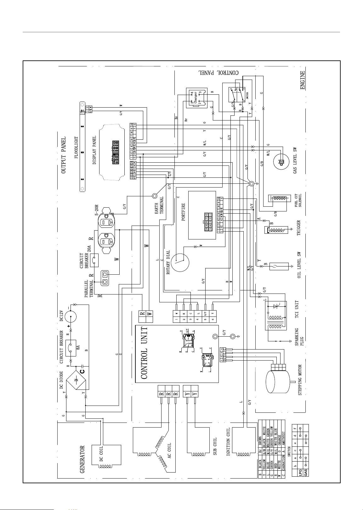
Wiring Diagram
OUTPUT PANEL
_
DC12V
+
R
CIRCUIT BREAKER
R
DC DIODE
Y
2
-
+
1
2
1
FLOODLIGHT
CIRCUIT
BREAKER
PARALLEL
8A
B
C
Y
W
G/Y
DISPLAY PANEL
5-20R
R
20A
R
TERMINAL
R
WARRANTY*
CONTROL PANEL
b
f
c
B
3
4
Charger
2
W
G/Y
O
10
Y
9
8
7
6
1
3
5
P1
79
P2
11
13
15
G/Y
2
W
5
4
6
3 4
8
G/Y W/L
10
G
2
12
G
1
14
16
16
15
G/Y
L C B W
1112 13 14
G/Y
Br
G/Y
1
G
Br
Y O
W/L
G/Y
G/Y
e
a
B
G/Y
B
C
G/Y
G
SWITCH
d
Y
Y
G
W/L
G/B
G/Y
G/Y
C
G/Y
EARTH
TERMINAL
PORTFIRE
W
W
L
C
W
ROTARY DIAL
Y
10
9
8
7
G/Y
6
W/L
12
W
5
7
3
8 6
9
4
O A
2 3 4
5
10
1
L
W
G/Y
B
G/Y
G/B
A
B
Y
B
W/L
G/Y
G/Y
L
Y
B
234
Y
W
L
C
G/Y
6
5
L
G/Y
4
6
5
2
3
1
Y
C
G
3
1
W
G/Y
C
4
3
2
4
1
O Y L C
2
L
R
W
G
G
W
1
ENGINE
GAS LEVEL SW
FUEL CUT
SOLENOIL
TRIGGER
OIL LEVEL SW
TCI UNIT
PLUG
SPARKING
CONTROL UNIT
RRR
Y
Y
L
G/Y
STEPPING MOTOR
G
G
f
d
BROWN
GREEN YELLOW
BLACK WHITE
WHITE GREEN
Br
W/G
B/W
BLACK
B
BLUE
YELLOW
L
Y
G/Y
GREEN
G
SUB COIL
DC COIL
AC COIL
IGNITION COIL
GENERATOR
ORANGE
WHITE BLUE
O
W/L
RED
WHITE
R
C CARNATION A AMETHYST
W
e
c
SWITCH
a
b
LPG
GAS
30
Page 31

Champion Power Equipment Europe
Service & Technical Contacts
United Kingdom:
BPE Holdings
Unit 17-18
Bradley Hall Trading Estate
Bradley Lane, Standish
Wigan, WN6 0XQ, UK
Tel: +44 (0) 1942 715 407
[email protected]
Sweden:
BPE Nordic AB
Valnäsgatan 2
44252 Ytterby
Sweden
Tel: +46 (0)31280985
[email protected]
Germany:
BPE Solutions Deutschland GmbH
Altrottstraße 31
D-69190 Walldorf
Germany
Tel: +49 6227/655996-3
[email protected]
France:
BPE Solutions France SAS
3 Boulevard de Belfort
59000 Lille
France
[email protected]
 Loading...