

Page 1
The Dishwashing Machine Specialists
Equipment Manual
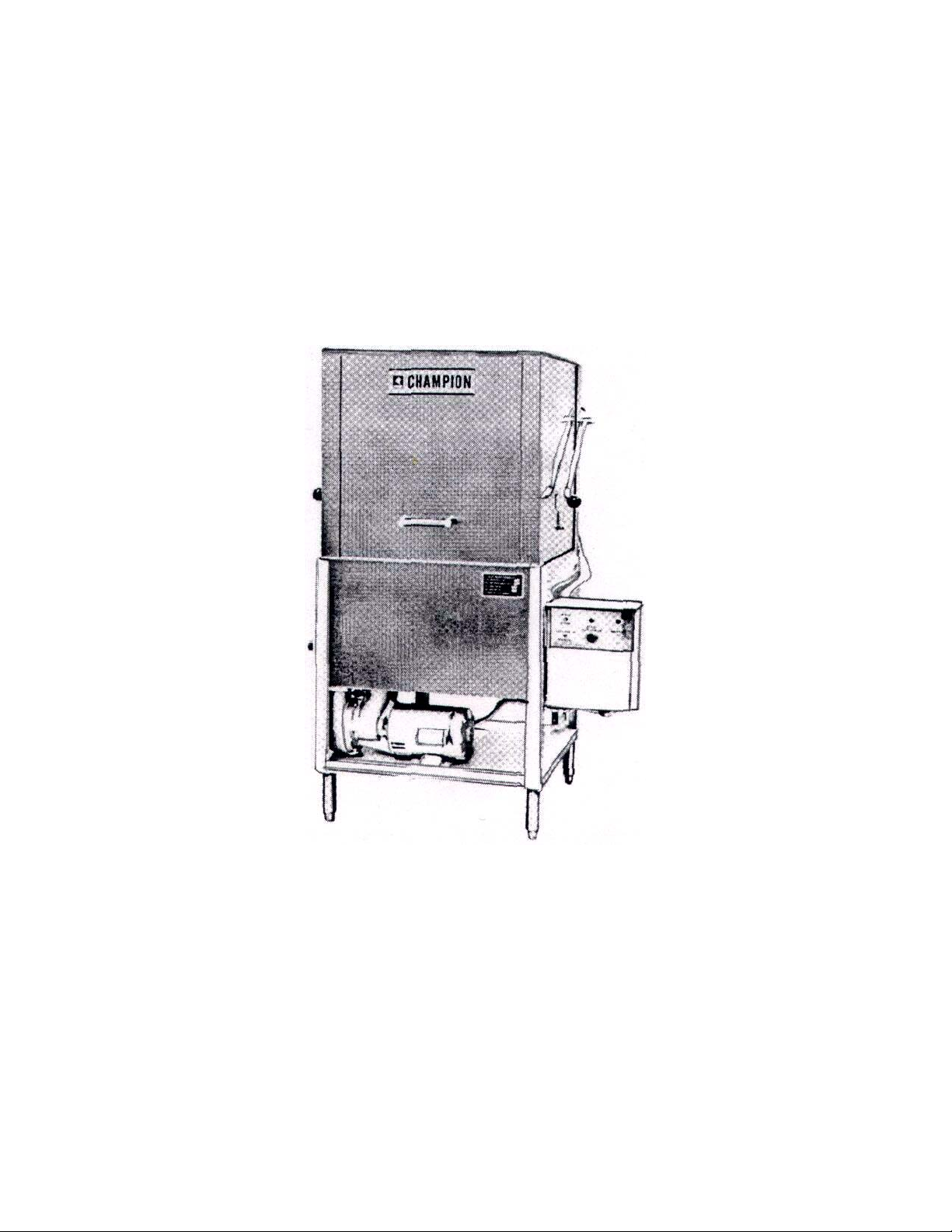
Champion
Dish Washer Models 1 KAB & 1 KACB
Part No. 108108 January 1990
Champion Industries, Inc. P.O. Box 4149 Winston-Salem, NC 27115 336/661 -1556 Fax 336/661 -1979
Page 2

GENERAL
Introduction
Directional Reference
1
1
Ordering Parts 1
INSTALLATION
Installation Instructions 23
OPERATION
Operation Instructions 4,5
MAINTENANCE
Procedures 6
Service Tips
Trouble Shooting — Specific Problems
6
6,7,89
Maintenance Schedule 910
Special Maintenance
PARTS BREAKDOWN AND LISTINGS
10,11,12,13,14
Hood and Base Assemblies
For Model 1-KAB 15
For Model 1-KACB
16
Installation on Door Lever
For Model 1-KAB 17
For Model 1-KACB
18
Control Panel 19
Upper Revolving Wash assembly
Lower Revolving Wash and Rinse Assemblies
20
21
Wash System Installation 22
Pump assembly
Drain Assembly
Rinse and Fill Piping
Electric Heat Installation
Gas Heat Installation
Steam Heat with Injector and Electric Thermostat Installation
Closed Coil Steam Heat with Electric Thermoswitch Installation
Steam Booster Piping
Door Lock and Safety Switch Installation
Electric Schematic
Steam Heat
Gas Heat
34
23
24
25
26
27
28
29
30
31
32
33
NOTE: Champion Industries, Inc reserves the right to modify the design and
specifications of the Model 1 -KAB dishwasher at anytime and without prior
notice This would be done in the interest of maintaining equipment approval
under applicable standards and codes and also to assure that Champion
Industries products reflect the advantages of a continuing research and
development program
Page 3

CAUTION: DO NOT OPERATE PUMPS NOR TURN ON HEATER
NOTE: Exercise care when uncrating and
moving your dishwasher to Its permanent location. Protect your investment
from the start.
1. Use a Nail Remover — NOT a hammer — remove the
shipping case and move the machine on skids to a
position near its permanent location.
2. Cut the steel strapping that secures the machine to the
skids. With at least two men, tip the dishwasher
enough to unscrew the adjustable feet about one inch
to give a nominal table connection height of 34 inches.
"Walk" the dishwasher off the skids and slide it into the
permanent location.
3. Level the machine by placing a spirit level on the base
and adjusting the feet Level side-to-side as well as
front-to-back.
4. The electrician should check the electrical characteristics labeled on the machine against the power
supply prior to connecting to the incoming service at a
fused disconnect switch. See Figure 1 or 2 for the
appropriate model.
MACHINE INSTALLATION
WITHOUT WATER IN THE TANK.
Pumps operated dry will cause
mechanical seal to burn up and leak.
8. Untie the upper and lower wash spray manifolds. i
9. Manually spin the revolving wash arms to make sure
they rotate freely.
10. Open and close the doors several times to make sure
they operate freely.
11. See that refuse screens are in position, resting on the
angle supports above the tank.
NOTE: Close pet cock located In bottom of
pump before filling tank.
12. When all plumbing and electrical connections are
completed, fill the tank with water and let stand fora
period of thirty (30) minutes: check for possible leaks
in the service connections Run the pump to check for
proper rotation in accordance with the indicating arrow
on it. Also check out automatic time cycle and manual
controls.
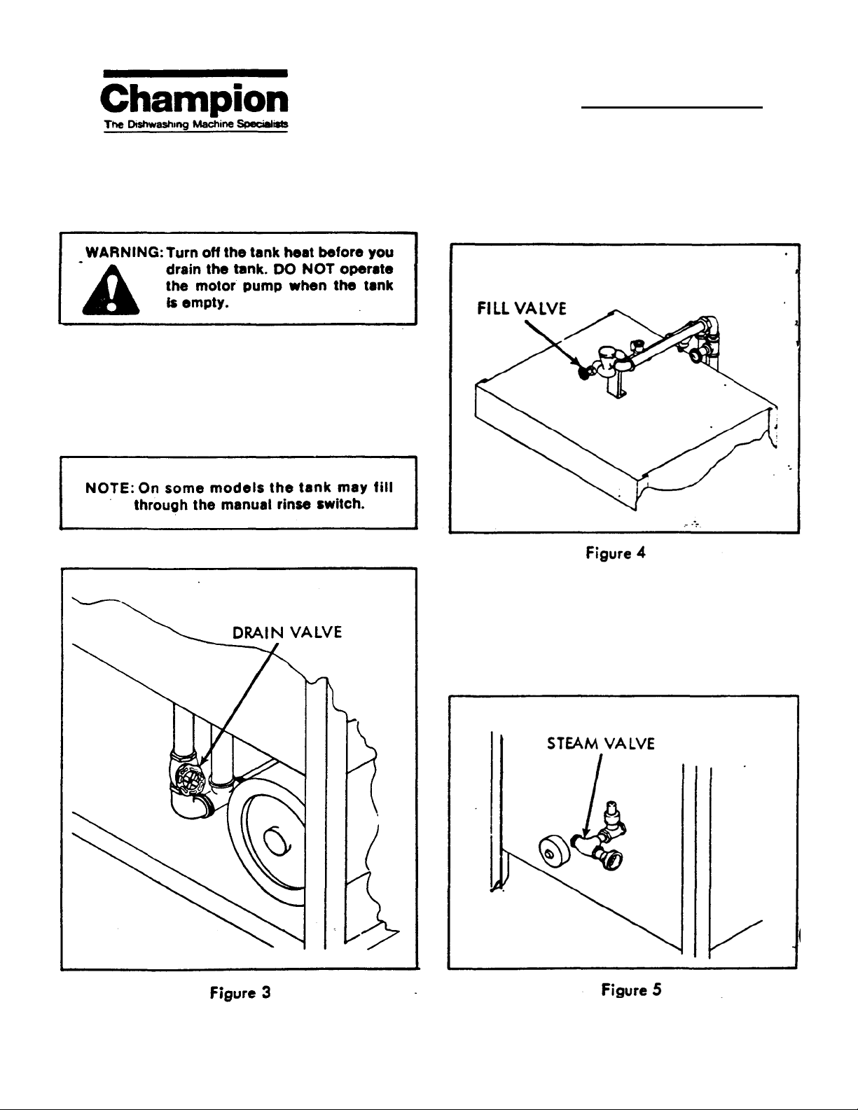
13. Open the drain valve and check all waste line'
connections for leaks. (See Figure 3)
14. After completing Steps 1 through 13. attach dish
tables to each end of the dishwasher.
NOTE: All wiring must be done according to
local electrical codes.
5. The plumber should make all connections for water,
steam and/or gas — if your dishwasher is so equipped
— as well as the drain to the sewer line. (See Figure 1
or 2 for the appropriate model).
6. Install shutoff valves in the steam and water supply
lines at points nearthedishwasher before installing the
hot water and steam connections. All plumbing
connections should comply with local codes.
7. Check the interior of the dishwasher and remove any
foreign material.
NOTE: Dish tables are pitched slightly toward
machine for proper draining.
Page 4

MACHINE INSTALLATION
Page 5
OPERATION
Operation of the Champion Dishwasher Model 1KAB or 1-KACB is fairly simple; however, you
should pay close attention to the following
instructions and recommendations for ensuring
efficient operation as well as long life.
1. Be sure that all wash and rinse spray pipes, rinse
nozzles and scrap screens are clean and in place.
Close the doors.
2. Close the tank drain valve (See Figure 3). Open the fill
valves; shut off when the tanks are fulKSee Figure 4).
3. Spread a half-pound (one cup) of detergent over the
screens in the wash compartment or. if an electronic
dispenser is used, check-and replenish the supply of
detergent in the dispenser. Turn on the dispenser
switches.
4. Turn on the steam valve if your dishwasher model is
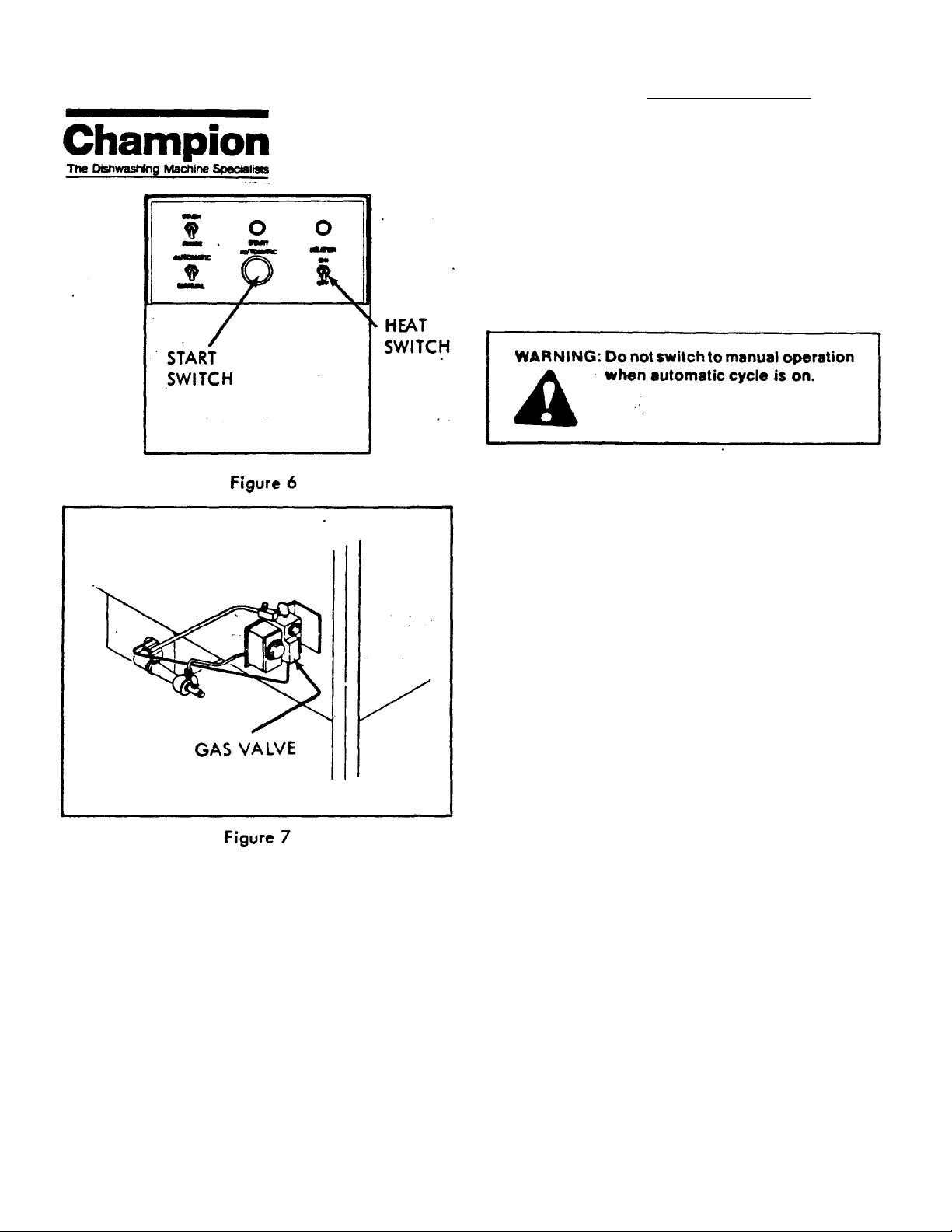
steam-heated (See Figure 5). Turn on the electric heat
switch if electrically heated (See Figure 6). Turn on the
gas valve; be sure the burners are lit if gas-heated (See
Figure 7). Open the valves on the water and steam line
to the booster (if your model has one).
Page 6
OPERATION
wash-rinse cycle is complete when pilot light goes out.
For manual operation, put the selector switch on
"Manual". Switch the control to WASH for a minimum of
45 seconds. Depress the control to rinse and hold for 10
seconds minimum.
8. For best results, clean the tank-screens and change
the wash water each hour of operation Renew the
detergent according to Step No. 3.
9. When washing is complete, turn off the tank heat
according to Step No. 4.
10. Throw the main power switch to the "OFF" position.
11. Remove and clean the scrap screens Place them on
the dish table to allow the tanks to air out and dry.
Remove the spray pipes and caps: clean the pipes with
a brush. Replace the caps and install in the machine.
5. Throw the main power switch on the "ON" position.
6. Scrape or pre-flush all pieces to be washed. Place .all
items in their proper racks. Do not overload racks.
Sprays must hit all surfaces. Wash one layer only of
silver in the rack. (See maintenance procedures for
proper tank temperatures).
7. Slide the loaded rack to the center of the machine.
Close the doors. Start the automatic timer by pressing
the starter switch (See Figure 6). The
NOTE: Do not hammer the spray pipes.
12. Clean the tanks and flush with fresh water.
13. Leave the doors open between operations to allow the
interior of the machine to dry.
14. Keep the machine clean and final rinse nozzles free of
internal hard water deposits by using a straightened
paper clip to remove solids from the nozzles. Consult
your detergent supplier of the use of scale solvents.
15. Report unusual conditions to your supervisor.
Page 7

p
p
PREVENTIVE MAINTENANCE
A well maintained Dishwasher periodically drained and
cleaned will give better service. On the other hand. a
machine that is neglected will soon clog up with deposits,
break down prematurely. Keep your "machine on the job.
not on the sidelines.
PROCEDURES
1. Each day — It will pay — to make a brief inspection of
the Dishwasher. Check the pump motor for leaks
around the shaft; check thermometers and gauges for
proper readings. Proper tank temperatures are 150° F.
minimum to 160° F. maximum (pumped) for the wash
cycle, 180°F. minimum to 200° F. maximum (fresh
water) for rinsing. If necessary, adjust the control(s) to
the correct setting(s).
TROUBLESHOOTING
2. Certain parts of the Dishwasher should be inspected
and cleaned each day. as required (See Maintenance
Schedule).
3. Once a week, inspect all water lines for leakage and
tightness at joints.
SERVICE TIPS (Trouble-Shooting)
1. Prior to determining the specific cause of any
breakdown or abnormal operation of the Dish- • washer:
(a) Be sure all switches are ON.
(b) Position the scrap screens in the tank. ,
(c) Check the position of the spray pipe (slots in the
upper pipe must be on the lower side. slots on the
lower pipe must be on the upper side).
After all above items have been accomplished, con-sult
the following table for particular service problems.
CONDITION
1. Insufficient Pumped Spray Pressure
ward discharge outlet on pump: raised
arrow on discharge port gives direction
on rotation.
-Check scrap screens (screens must be
-Check and clean spray pipe.
- Check water level in tank (tank must be
-Check drain valve for leaks (valve must
be closed when machine is in use.)
2. Low or no final rinse pressure -Check incoming pipe size (may be un
dersized).
-Check
ished; clean and adjust upward to 20psi
PROBABLE CAUSE and SOLUTION
-Check motor rotation (must rotate to
-Check for clogged pump intake and
discharge.
kept clean).
full).
ressure reducing valve, if furn
optimum flow pressure at machine.
- Check for worn rinse nozzles; oversized
or worn nozzle parts will tend to de
crease rinse
ressure.
Page 8

)
y
t
TROUBLE SHOOTING - (CONT'D)
CONDITION
2. Low or no final rinse pressure (cont'd
-Check for fault
3. Low final rinse temperature -Check incoming water — 140° F. mini
PROBABLE CAUSE and SOLUTION
vacuum breaker (sea
must be in good order).
-Check rinse solenoid valve for proper
operation or possible burned out coil.
mum to booster. 180° F. minimum with
out booster. Temperature at nozzles
MUST be 180° F. MINIMUM.
-Check the booster — be. sure the.thermoswitch is set to maintain 180°F. tem
perature; check all valves. Be sure all
are open. clean and operating.
-Check the piping, may need insulating.
NOTE: Dishwasher must not be installed on the same supply line with
other equipment using hot water
supply needed for the machine.
4 Low or No Tank Heat Temperature
Electric Heat
-Check: Heaters for correct voltage.
phase, and operation.
Power source to heater — be
sure disconnect switch is in
"ON" position.
Electrical heater thermostat for
proper calibration and setting.
Heater contactor inoperative.
For free operation of low water
cut-off inside tank.
- Refer to electrical diagram in parts sec
tion of manual.
Steam Heat
-Check all valves and flow pressure as
well as the trap.
Gas Heat
-Check the burner and gas supply.
Page 9

)
TROUBLE SHOOTING - (CONT'D)
CONDITION
4. Low or No Tank Heat Temperature
(Confd) operation.
PROBABLE CAUSE and SOLUTION
General: (all types of heat)
- Check: Thermoswitch for setting and
Low water cut-off switch.
Thermometer for proper cali
bration.
Heat contactor and heat switch,
Heaters and coils for soil build
up -- clean if evident.
NOTE: Tank temperatures should be:
Wash cycle - 150°F. Min.
160° F.Max, (pumped
Rinse cycle - 180' F. Min.
200° F. Max. (fresh water)
5. Low water condition in tank
6. Poor Washing Results For overloaded rack causing
-Check: Drain valve — be sure, it is
closed.
Drain valve and overflow box for
leaks.
- Check: For proper amount of detergent.
blocked sprays.
Wash water and detergent not
changed often enough.
NOTE: Water in wash tank should be
changed after each hour of oper
ation.
Dishware improperly placed in
rack.
NOTE: Be sure operator is not pushing
rach of dishes into machine past
washing cycle.
Page 10

p
TROUBLE SHOOTING - (CONT'D)
CONDITION PROBABLE CAUSE and SOLUTION
7. Poor Drying Results -Check: For excessive humidity in dish
antry.
Exhaust fans for proper function.
Final rinse water temperature —
180° F. Min.
Improperly stacked dishes after
washing.
MAINTENANCE OF THE DISHWASHER
Scheduled maintenance saves down time and headaches. The chart below is designed to aid you in keeping
your dishwasher on the job. It's a well known and widely
accepted fact that well maintained machines do not
break down as frequently as machines receiving only
occasional care — or no attention at all. It will take only a
few minutes to give your Champion Dishwasher the small
amount of care it deserves. Take the time — your
dishwasher will pay you dividends in the form of many
troublefree hours of faithful service.
The time intervals shown in the maintenance schedule
represent the average lengths of time that various parts of
the Champion Dishwasher should go without service
Maintenance intervals should be shortened:
whenever the machine is faced with poor working
conditions— hard water, etc. — or multiple shift operation.
REGULAR MAINTENANCE
Daily or Every 10 Hours: Shut down machine — pull main switch —
• Leave doors raised to air interior.
As Required — daily, or otherwise: Check thermometers and gauges for read
Every Week: Thoroughly clean detergent residue from ex
check following and clean, if required:
- Drain tank and flush with water.
-Empty and clean scrap screens
• Flush out 'garbage disposer.
- Remove all spray pipes (wash and rinse) —
inspect and clean.
-Wash inside of machine with fresh water.
also tank, side and top of machine.
ings and adjust controls to proper settings.
terior of machine.
Page 11
REGULAR MAINTENANCE (CONT'D)
Every Month: Check the drain valve for leakage (drop in
Every Three (3) Months: Grease or oil all shafts with fittings except
Every Six (6) Months: Grease motors with fittings (if no fittings, see
water level in still tank of over 1 to 2 inches
per hour).
Electric Heat (see Special Maintenance).
Clean accumulated scale and coating off heat
ing elements.
Check and clean stem of float switch.
Check operation of thermostat.
pump motor with good grade of ball bearing
grease or high Quality lubricating oil.
Special Maintenance) with good grade of ball -.
bearing grease or according to label on each.
SPECIAL MAINTENANCE
CHAMPION MOTOR-PUMP UNIT: D-756
The integral motor-pump assembly, shown in Figure 8,
was developed for maximum performance, adherence to
the latest sanitation reQuirements and sound engineering
design. New NEMA frame sizes have been adopted;
however, they are interchangable with the older and larger
NEMA frame sizes.
The pump mounting ring bolts onto the motor "End Shield"
and the motor shaft extends into the pump housing,
eliminating the need for a separate pump. One seal only is
reouired in this assembly.
The exclusive "inside suction" design of this pump premits
removal of the entire cover of the pump housing as an
access plate, allowing unrestricted access to the impeller
and interior of the pump chamber. When the seal has worn
to the point of replacement, it is easily reached by
removing the access plate cover of the pump and the bolt
holding the impeller on the shaft. Withdraw the impellersleeve assembly. Oil the shaft lightly to facilitate
withdrawing the seal.
NOTE: DO NOT over lubricate.
NOTE: A number 5 wheel puller will aid in removing the impeller.
Before installing the new seal, be sure the tapered cavity is
smooth and free of dirt. Again lightly oil the shaft, the
outside rubber ring of the seal and wall of the cavity of the
pump.
After the impeller-sleeve assembly is in place — also the
key — install the fibre washer, metal washer and bolt. As
the bolt is tightened, the seal will be automatically
compressed to the proper working height. No other
adjustment is necessary.
Page 12

Keep the pump motor clean and lubricate according
tothe Maintenance Schedule. If the motor is not
equipped with grease fittings, remove the plug (screw)
on top front and rear of motor and install the fittings.
NOTE: DO NOT OVER LUBRICATE - one or
two pumps of the grease gun are
sufficient.
SOLENOID VALVES
Periodically clean all solenoid valves. Time between
cleanings will vary, depending on use and service
conditions. Generally, if voltage to the coil is correct.
sluggish valve operation or excessive leakage indicates
cleaning is required.
If the valve fails to operate properly, compare the
electrical service and line pressure with the service and
pressure shown on the nameplate of the valve A metallic
"click" is heard if the solenoid is operating Absence of the
"click" indicates loss of power supply. Check for loose or
blown-out fuses, grounded coil, broken lead wires or
connections.
To replace the coil, TURN OFF ELECTRIC POWER AND
LINE PRESSURE to the valve. Remove the coil cover,
washers, gaskets and retaining clip and disconnect the
coil lead wires. Replace the coil with a new coil of the
same voltage. Replace the gaskets, washers and cover.
Page 13
For leakage, examine the internal parts for wear or
binding; also inspect the diaphragm or disc for weardirt may have accumulated on the valve seats or
diaphragm and disc. If parts must be replaced, use
only the same make of parts as the valve; also
replace as supplied in repair kit (See section for
description).
MANUAL VALVES
Leakage of water from the tank of the dish washer over 1
to 2 inches per hour when machine is not in use indicates
wear on the internal parts of the drain valve. If the seat is
worn, replace.the complete valve.
When dishwasher is not in use and tank continues to fill,
wear on the internal parts of the fill valve is indicated.
Replace the stem assembly or replace the complete valve
if the seat is worn.
VACUUM BREAKER
Only the disc in the vacuum breaker can be replaced if
leakage is excessive. If the seat is worn, replace the
complete vacuum breaker.
PRESSURE REDUCING VALVE (PRV)
Leakage of water from the PRV valve wil cause loss of
pressure to the machine. If the valve is leaking or
networking, installthe complete service kit. (See Parts
Section).,
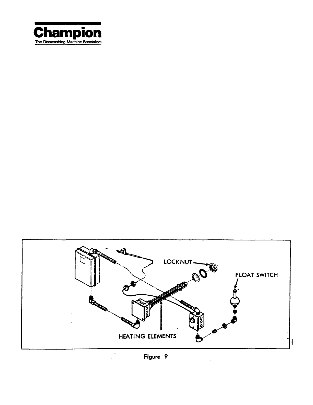
ELECTRIC HEAT
The electric heat with low water cut-off and thermostat
(Shown in Figure 9) was developed for maximum
performance, adherence to the latest in sanitation reQuirements with minimum maintenance and replacement.
1. Every month clean the accumulated scale and coating
off the heating elements. Check for pits.
2. Check and clean the stem of the float switch at least
once a month. Check the spring clip on the float to be
sure it is fastened securely. Be sure the float is installed
correctly—the normally-open side should be up — and
that the ball float moves up and down, freely.
3. Check operation of the thermostat at least once a
month.
NOTE: Should the dishwasher be emptied of
water, and the heater left in operation, the
low water cut-off will cut the heater off
without damaging the heating element.
The heater will come on when the tank is
filled to its proper level and the heat
switch is "ON".
In the event of failure of-a heater, the heater can be
removed without removal of the low water cut-off and
thermostat. Remove the heater from the tank by disconnecting the wiring to the heater — be sure the power
is "OFF" — remove the locknut, and remove the heater
from the tank. Install a new heater in the tank using a
sealant on the face of the heater and on the locknut.
tn the event of failure of the low water cut-off thermostat. it
can be replaced without removing the heater. Remove
only the unit to be replaced. Be sure the power is OFF
before removing.
Page 14

GAS HEAT—VALVE
DESCRIPTION
The valve is a combination gas valve which provides all
manual and automatic control functions required for
operation of gas fired heating equipment. This valve is
suitable for use with all gases.
OPERATION
Electric power (millivoltage) for operation of the valve is
produced by a generator. The 750 millivolt generator is
used when valve is to be controlled by a remote
thermostat.
With proper pilot flame established, main valve operator
is opened and closed by thermostat to maintain constant
temperature. If pilot flame goes out or be-comes low or
unstable, safety valve closes, shutting off both pilot and
main line gas.
INSTALLATION
Use valve within following operating ranges:
Maximum operating pressure: 1/2 psi (14"WC)
Minimum operating pressure: 1 oz. (2"WC)
Maximum ambient temperature: 175°F.
1. Valve is multi-poised and may be mounted in any
position. Inlet and outlet connections are marked on
valve body.
2. Make sure all piping and tubing is free of foreign
matter. Apply thread seal to male threads only.
3. Connect 1/4" pilot tubing between valve and pilot
burner assembly. Pilot burner assembly must be
mounted rigidly in a position where pilot will ignite
main burner when it has been reduced to smallest
flame which will hold thermo magnet safety valve
open.
4. Venting is internal and requires no attention.
5. Make sure all wiring connections are clean and tight.
LIGHTING PROCEDURE
1. Turn to PILOT. Press dial in and
light pilot. Hold for 60 seconds and
release.
2. Turn dial counter-clockwise to ON.
Use this position for thermostat control.
Set -thermostat for desired room
temperature.
3. Press dial in and turn clockwise to
OFF. Use this position when complete
shutdown is necessary. (Use PILOT
position for temporary or seasonal
shutdown.)
NOTE: When valve is turned OFF, dial
on models equipped with Safety-Lock
cannot be turned to PILOT for relighting until after three
minutes. Do not attempt to force dial.
Pilot Gas
Remove pilot adjustment cap screw and turn pilot
adjustment screw to produce non-blowing blue fame
surrounding generator cartridge. Replace cap screw.
Pressure Regulator (Optional)
Regulator has been factory adjusted to value stamped
on valve: i.e., 3 1/2" W.C. To adjust regulator, remove
pipe plug from W NPT pressure tap near valve outlet and
install pressure measuring device. Remove cap screw
and turn adjustment screw clockwise to increase
pressure, counter-clockwise to decrease pressure.
Replace pipe plug and cap screw.
SERVICE
For efficient operation, pilot must burn with non-lowing,
blue flame surrounding generator cartridge. All wiring
connections and splices must be clean and tight.
Sluggishness or failure in valve operation usually
indicates pilot generator is not producing sufficient
millivoltage or that a power loss is occurring somewhere
in the system.
Checking with a millivoltmeter Is the quickest method of
locating trouble in the system.
Page 15

MILUVOLTMETER TEST
Use a 0-500 millivolt scale. Place meter test probes or
clips as indicated below. If meter needle moves to left of
zero or no reading is indicated reverse probes. Take all
readings with pilot burning and thermostat contacts
closed.
Generator Check
Thermostat reading "A" should be 20 millivolts or less
without anticipation or 100 millivolts or less with
anticipation. If higher, check all wiring and terminals.
Replace thermostat and/or limit control. Generator
reading "B" should be 140 millivolts or more closed
circuit. If lower, clean pilot burner orifice and primary air
holes. Replace generator if necessary.
A "Pilot Generator" provides a pilot flame for ignition of
gas burners and generates electricity from the heat of the
pilot flame for reliable operation of millivolt gas valves and
relays.
INSTALLATION
Main burner flame must not hit the generator cartridge or
the snorkel tube. Mount pilot burner securely with respect
to main burner. Perform field test to assure safe ignition.
Readjust pilot gas flow for safe, steady, non-blowing blue
flame.
FIELD TEST FOR SAFE IGNITION (Turn
Down Test)
WARNING
WITH PILOT GAS REDUCED TO LOWEST POINT
WHICH WILL GENERATE THE MILLIVOLTAGE REQUIRED TO OPEN VALVE, THE MAIN BURNER MUST
LIGHT OFF SMOOTHLY. IF IGNITION IS DELAYED
DURING TEST, IMMEDIATELY SHUT OFF GAS. WAIT
5 MIN. BEFORE CONTINUING TEST.
1. Disconnect one pilot generator wire from valve terminal. Jumper thermostat terminals of valve.
2. Open pilot gas valve. Light pilot and adjust for
MAXIMUM pilot flame. Check appearance to be sure
flame is in proper position to ignite burner.
3. Open main burner gas cock. Touch and hold the loose
pilot generator wire to valve terminal. Burner should
light off smoothly within a few seconds.
4. Reduce pilot flame by adjustment valve until flame
around cartridge is about Vs of maximum. Wait two
minutes for generation to stabilize. Touch and hold the
loose pilot generator wire to valve terminal. If valve
opens, burner should light off with no delay. Again
reduce pilot gas flow slightly, wait two minutes, and
test. Repeat until pilot flame is too low to produce
sufficient millivoltage to open valve. Reposition pilot
generator if necessary.
5. Remove jumpers from valve and reconnect all wires in
their original positions. Make all wiring connections
clean and tight. Readjust pilot gas flow for blue, nonblowing flame surrounding the generator cartridge. Be
sure the main burner flame does not hit generator
cartridge or snorkel.
SERVICE
If the top %" of the cartridge is not heated sufficiently by
a well defined blue ring of flame, the complete control
system may operate sluggishly. The pilot orifice may be
removed for cleaning or changing by unscrewing the
orifice base fitting. On old style units, a clip holds orifice
in place. In the event of damage, replace generator
cartridge. Be sure replacement cartridge is fully inserted
when clip is reassembled.
MILLIVOLT METER TEST
The only satisfactory method of testing a pilot generator
is with a millivolt meter. Using 0 to 500 or 0 to 1000
millivolt scale, connect the meter leads to valve or relay
terminals to which the pilot generator wires are attached.
Be sure the pilot is burning and all thermostats and other
switches are ON calling for heat.
MILLIVOLTMETER CHECK
Page 16

HOOD AND BASE ASSEMBLIES
(Model 1-KAB)
Item Port No.
1
2
3
4
5
6
100125
201029
201041
401641
303284 •
304807
Door Roller
A4408-1
Oty. Description Item Port No. Oty. Description
1 THERMOMETER 7 00735
1 LOCKNUT 8 301105
1 SPACER 9 D5673
1 CATCH ASSEMBLY 10 200087 1 INDICATOR, WATER LEVEL (optional)
TRACK 11 100012 1 HANDLE
2
SCREEN 12 107245 3 ROLL PIN 3/32" x 3/8"
4
3 DOOR (includes item 8)
WEAR STRIP
6
1 CONTROL CABINET (see poge 19)
Page 17

HOOD AND BASE ASSEMBLIES
(Model 1-KACB)
Item Part No.
1
2
3
4
100125
201029
201041
D6386-1
5
6
7
8
304785
C4681-1
304787
B3320-1
Qty. Description Item Part No.
1 THERMOMETER
1 LOCKNUT 10 304787 1 ANGLE
1 SPACER 11 301105 6 WEAR STRIP
1 TRACK ASSEMBLY 12 400735 3 DOOR (includes item 11)
(consists of items 5 thru 10) 13 200087 1 INDICATOR, WEAR LEVER
1 TRACK, rear (optional)
1 TRACK, right side 14 1 CONTROL CABINET
1 ANGLE, cross
1 BRACKET
9 100035
15 304807
Oty. Description
1 SPACER
(see page 19)
4 SCREEN
Page 18

INSTALLATION OF DOOR LEVER
(Model 1-KAB)
Item
Part No.
1
2
3
4
5
f
303296
106915
106913
106914
106168
104646
Qty. Description
1 LEVER, door
2 WASHER, pivot block
2 BLOCK, pivot
2 BLOCK, pivot
2 BRACKET
2 LINKAGE, spring
Item
6
7
8
9
TO
Part No.
401120
105299
106169
106565
100145
Qty. Description
1 SPRING ASSEMBLY,
pre-loaded
2 SLEEVE
2 BOLT, shoulder
2 LINK
2 KNOB
Page 19

INSTALLATION OF DOOR LEVER
(Model 1-KACB)
Item
1
2
3
4
5
6
7
8
9
Part No.
401120
104646
105643 1 LEVER,door
401164 1 PIVOT
401165 1 PIVOT
106166 2 LINK
104648 2 SPACER
106168 2 BRACKET
104648
Qty. Description
1 SPRING ASSEMBLY
1 LINKAGE, spring
2 SPACER
Page 20

PART NUMBER
401120
100143 6 HUT GRIP 3/8-16 2
107177
201048 2 TUBING SPRING COVER SST. 1
104647
201049 3 LINK SPRING FORMED NOT PIA 1
ITEM NO
4
1
DESCRIPTION QTY/PER
SPRING ASSY
BOLT 3/8-16 X 2 3/4 HEX HE 2
SPRING EXTENTION 1
Page 21

CONTROL PANEL
Item Part No.
1
2
3
4
5
6
7
8
9
104630
100906
104709
101151
101180
100326
100316
100305
101181
OPT. TIMED TANK FILL -108251
40032501 -30 HRS
40032502 -30 SST
40032503 -10 HRS
40032504 -10 SST
Qty. Description
1 TRANSFORMER 10 102324 1 TIMER (120V)
1 FUSE 10 104513 1 TIMER (220V)
1 RELAY (2 req'd gas heat) 11 100336 1 RELAY (3 phase)
2 LIGHT 12 100327 1 RELAY (single phase)
1 SWITCH, wash/rinse 13 HEATER, overload*
1 SWITCH, heat 14 106876 1 CONTACTOR
1 PUSHBUTTON 15 100293 1 BLOCK, terminal
1 BLOCK 16 104628 1 DECAL
1 SWITCH, auto/manual Specify number and size of heater.
Item
Port No.
Qty. Description
Page 22

UPPER REVOLVING WASH ASSEMBLY
Item
1
2
3
4
C4081-1
Part No.
106252
B236-1
C4905-1
5
6
8236-2
1001054
Qty. Description Item Part No.
1 ADAPTER, upper rotary wash
2 BEARING 8 104794 3 PIN, sproy pipe lock
1 PIPE, spray
1 MANIFOLD, upper rotary 10 100163 1 NOZZLE, vee jet
wash 11 B236-3 1 PIPE,spray
1 PIPE, spray
3 SCREW, thumb
7 201065
9 104793
Qty. Description
3 NOZZLE, drive
1 BOLT, manifold lock
Page 23

LOWER REVOLVING WASH AND RINSE ASSEMBLIES
Item Part No.
1
2
3
106170
106253
B3407-1
4 202801 1 PIPE, rinse 10 C4546-1 1 ADAPTER, lower wash/
5
6
104010
100210
Qty. Description
1 KNOB, knurled
2 BEARING 8 401464 1 MANIFOLD ASSEMBLY,
1 MANIFOLD, revolving
rinse - (includes item 2) 9 106625 2 CAP, pipe 3/4" NPT
12 NOZZLE
2 PLUG 11 202281 1 PIPE, rinse
Item Part No.
7 106251
Qty. Description
1 BEARING
lower wash
rinse
Page 24

WASH SYSTEM INSTALLATION
Item Part No.
1
2
3
4
C4479-1
304816 1 STRAINER
104640
104638
Qty. Description
1 STANDPIPE
1 GASKET, pump suction
2 GASKET, pump discharge
Page 25

PART NUMBER
401464
C4111-1
C4111-2
C4324-1
106503
ITEM NO
1
2
3
4
DESCRIPTION
LOWER WASH ARM - SUB-ASSY
SPRAY PIPE
SPRAY PIPE
MANIFOLD WITH BEARING 1124
SCREW #6 X 1/4 DRIVE
QTY/PER
1
1
1
2
Page 26

PUMP ASSEMBLY
Item Part No.
1
—
2
3
4
5
6
7
14217-1
100038
104619
100153
401692
104916
30—401699/401698-10
Qty. Description
1 MOTOR, 1 HP - specify
voltage and phase)
1 HOUSING, pump suction
1 SEAL 11 100735 16 BOLT
1 WASHER, flat
1 BOLT, impeller
1 IMPELLER
1 KEY
Item Part No.
8 104617
9 C3820-1
10 12672-1
12 100045
13 100153
14 104616
Qty. Description
1 GASKET, fiber
1 HOUSING, pump discharge
1 PLATE, impeller access
1 DRAIN COCK
4 BOLT
4 WASHER, star
Page 27

DRAIN ASSEMBLY
Item
1
2
3
4
5
6
7
Part No. Qty. Description
303317
104639 2 GASKET
202191
100178 1 VALVE
104791
104637 1 STUD
304816
1 PIPE, overflow
2 FLANGE
1 BONNET ASSEM8LY
1 STRAINER
Page 28

RINSE AND FILL PIPING
Item Part No.
1
2
3
4
5
6
7
8
100124
600710
100172
104749
104726
104429
104942
100054
Qty. Description
1 THERMOMETER
1 UPPER RINSE ASSEMBLY 10 104735 1 REPAIR KIT
4 NOZZLE
1 VALVE, ball 12 100135 1 GAUGE
1 HANDLE 13 104681 1 SILENCER
1 VACUUM BREAKER 14 104753 1 STRAINER
1 REPAIR KIT
1 VALVE, solenoid (110V)
Item
9
11
15
Part No.
104669
100123
105474
Qty. Description
1 COIL.110V
1 COCK, gouge
1 VALVE, pressure reducing
Page 29

ELECTRIC HEAT INSTALLATION
Item Part No.
1
2
2
2
2
2
3
4
5
100062
106098
107839
106099
107840
106100
104652
104651
100192
Qty. Description
1 CONTACTOR
1 HEATER, 5 KW 1/60/208 7 100544 1 ELBOW
1 HEATER, 5 KW 3/60/208 8 201029 1 LOCKNUT
1 HEATER, 5 KW 1/60/240 9 201758 1 NIPPLE
1 HEATER, 5 KW 3/60/240
1 HEATER, 5 KW 3/60/480 11 100883 1 CHASE NIPPLE
1 SPACER
1 GASKET 103376 1 THERMOSTAT less box
1 LOCKNUT
Item Part No.
6 100170
10 102514
12 104512
Oty. Description
1 SWITCH, float
1 TEE
1 THERMOSTAT box
Page 30

Item Part No.
1
101302
2
201758
3
201129
4
201030
5
100170
6
102087
7
A-3478-1
8
102258
8
104003
9
C1775
10
11
12
13
14
15
100976
A1539
100960
100954
B2860-1
100117
Qty. Description
1 BOX with cover
1 NIPPLE
2 LOCKNUT
1 ELBOW
1 SWITCH, float
1 TUBE, pilot
1 BRACKET
1 PILOT BURNER (not gas)
1 PILOT BURNER (LP gas)
1 PIPE, burner
1 CAP
1 HEAT CONDUCTOR
1 ELBOW
1 NIPPLE
1 BRACKET
1 VALVE (not gas)
Item Part No.
15
16
17
18
19
20
21
21
22
23
24
25
26
27
28
29
102257
102402
100680
100678
100432
102090
102246
102379
104606
100188
100115
201097
104610
101093
100137
100134
Qty Description
1 VALVE (LP gas)
1 BUSHING
2 FITTING
2 NUT
1 THERMOSTAT
1 TUBE
T VALVE (not gas)
1 VALVE (LP gas)
1 ZIP TUBE
1 NIPPLE
1 BUSHING
1 IOCKNUT
2 CLAMP
1 ELBOW
1 IOJECTOR
1 Ell, street
Page 31

STEAM HEAT w/ INJECTOR and ELECTRIC THERMOSTAT INSTALLATION
PART NUMBER ITEM NO DESCRIPTION QTY/PER
D1834-4
109069
104828 1 VALVE BALL 3/4 INCH 70-104 1
100548 3 LOCKNUT 3/4 1
105738 4 ELBOW 3/4 X 1/2 90 BI 1
3.05783 5 NIPPLE 1/2 X 2 BI 1
100147 6 STREET ELL 1/2 IN BI 1
201110 7 STEAM INJECTOR 1
101677 8 NIPPLE TOE 1 X 9 SST 1
100547 16 LOCKNUT 1/2 INCH NPT SST 1
106937 19 NIPPLE RTOE 3/4X1 3/4 FULL 1
105803 20 NIPPLE 3/4.CLOSE BI 1
108488 21 VALVE 3/4 120V STEAM 1
107922 22 BOX&COVER THERMOSTAT 2X3X4 1
1K 1KC STM INJECT W/THERMO
THERMOSTAT W/CAPILLA ESSEX
1
Page 32

/
/
/
/
/
/
/
/
/
/
CLOSED COIL STEAM HEAT WITH ELECTRIC THERMOSWITCH INSTALLATION
PART NUMBER ITEM NO DESCRIPTION QTY/PER
B1497-1 1-K 1-KC CLOSED COIL W/THM
109069 THERMOSTAT W/CAPILLA ESSEX 1.
104828 1 VALVE BALL 3
201263 2 LOCKNUT 3
D5980- 1 3 STEAM COIL 1.
201029 4 LOCKNUT 1
100113 5 CAP 3
100184 6 NIPPLE 3
108488 7 VALVE 3/4 120V STEAM 1.
107922 8 BOX&COVER THERMOSTAT 2X3X4 1.
100365 9 TRAP STEAM 1
100685 10 NIPPLE RTOE 3
102416 11 COUP REDUCE 3/4 X 1/2 BRAS 1.
102443 12 ELBOW 3
101500 13 NIPPLE 3/4 X 4 1/2 SST 1.
101544 15 NIPPLE 3
102554 15 UNION 3/4 SST 1.
100051 16 NIPPLE 3
104541 17 NIPPLE RTOE 3/4X15 1/2 SST 1.
4 INCH 70-104 1.
4 NI PLATED 3.
2 INCH NP 1.
4 INCH SST 2.
4 CLOSE BRASS 1.
2 25PSI 1.
4X2 1/2 1.
4 90 SST 4.
4 X 0 11/2 SST 1.
4 CLOSE SST 2.
Page 33

STEAM BOOSTER
Item Part No.
1
2
3
4
5
6
7
8
81383-2
100021
100263
100123
100135
100224
104722
104668
Qty. Description
1 BASE
1 BOOSTER 10 100128 1 THERMOSWITCH
1 STRAINER 11 100124 1 THERMOMETER
2 COCK, gauge
2 GAUGE 13 103385 1 VALVE, relief
1 VALVE, solenoid 14 105474 1 VALVE, pressure reducing
1 PISTON ASSEMBLY 15 104790 1 SERVICE KIT
1 COIL
Item Part No.
9 100366
12 104681
Qty. Description
1 TRAP
1 SILENCER
Page 34

DOOR LOCK AND SAFETY SWITCH
Item Part No.
1
2
3
4
5
6
7
8
9
10
100120 1 LOCKNUT
250001 1 BUSHING
105253
A861-3 1 PLUNGER
A3944 1 BRACKET
303311 2 STOP
106027 3 BOLT
100141 5 NUT
106014
107053 1 SWITCH
Qty. Description
1 SPRING
5 NUT, cap
Page 35

700134 ELECTRIC HEAT SCHEMATIC
Page 36

700135 STEAM HEAT SCHEMATIC
Page 37

700136 GAS HEAT SCHEMATIC
Page 38

PART NUMBER
500153
A1143
A3903
A4309-1
B236-1
B236-2
B236-3
B2686
B3407-1
C4081-1
C4479-1
C4546-1
C4905-1
D6078-2
100012
100029
100045
100054
• 100073
100094
100105
100115
100118
100120
100123
100125
100145
100163
100171
100172
100184
100206
100209
100210
100599
100709
102388
102435
102438
102444
102457
102471
102505
102525
102526
102549
102658
102683
102795
104010
104429
104644
ITEM NO
DESCRIPTION QTY/PER
1-KAB PARTS
BRACKET THERMOMETER 1.
FILLER FRONT 1.
STOP DOOR FRONT 1.
SPRAY PIPE 1.
SPRAY PIPE 1.
SPRAY PIPE 1.
SUPPORT SCREEN CENTER 1.
MANIFOLD RINSE 1K 1.
ADAPTER UPPER WASH 1120 1.
STANDPIPE ASSY 1.
ADAPTER LOWER 1K 1.
MANIFOLD PATT 1119 1.
HOOD ASSY 1KAB GAS 1.
HANDLE DOOR 1.
UNION 3/8 SST 1.
COCK DRAIN 1.
VALVE 3/4 INCH 120V 8210D9 1.
SCREW 1/4-20 XL/2 TRUSS HD 2.
WASHER 1/2 X 1 1/16 X 1/32 1.
SCREW 1/4-20 X 3/4 THUMB 3.
BUSH REDUC 1/2 X 1/8 B.I. 1.
UNION ELBOW 3/4 MALE 1.
LOCKNUT 3/8 1.
COCK GAUGE 1/4 41-500-01 1.
THERMOMETER 1.
KNOB DOOR 2.
NOZZLE 3/8 U-SS50120 1.
BUSH FACE RED 3/4X1/2 BRAS 1.
NOZZLE 3/8 HH18SO 4.
NIPPLE 3/4 CLOSE. BRASS 3.
NIPPLE 1/2 X 2 1/2 1.
NIPPLE 1/2 CLOSE BRASS 2.
PLUG 1/8 SST 2.
CROSS 3/4 BRASS 1.
LOCKNUT 1/2 BRASS 1.
BUSH REDUC 1/2 X 1/4 BRASS 1.
ELBOW 1/2 90 BRASS 1.
ELBOW STREET 1/2 90 BRASS 1.
ELBOW STREET 3/4 90 BRASS 1.
NIPPLE 3/8 CLOSE SST 1.
NIPPLE 3/4X3 1/4 BRASS 1.
PLUG 3/4 BRASS 1.
TEE 3/4 X 1/2 X 3/4 BRASS 1.
TEE 3/4 X 3/4 X 1/2 BRASS 1.
UNION 1/2 BRASS 1.
NIPPLE 3/4X5 1/2 BRASS 1.
NIPPLE 3/4 X 13 1/2 BRASS 1.
ELBOW STREET 3/8 1.
NOZZLE 5/16 12.
VACUUM BREAKER 3/4 IN BRASS 1.
SPRING MANIFOLD LOCKPIN 2.
Page 39

Champion
The Dishwashing Machine Specialists
PART NUMBER ITEM NO DESCRIPTION QTY/PER
500153
104646
104682
104686
104749
104753
104793
104794
105299
106168
106169
106170
106565
106625
106913
106914
106915
107342
107680
201029
201065
201097
201758
202280
202281
302394
303262
303278
303296
303530
304784
304796
304807
304816
400735
401120
401168
401464
403167
600511
990000
1-KAB PARTS
LINKAGE SPRING UPPER 1.
THERMOMETER 2 INCH STEM CB 1.
NIPPLE RTOE 3/8 X 11 1.
VALVE BALL 1/2 IN 70-80301 1.
STRAINER LINE 3/4 1.
BOLT MANIFOLD LOCK 1.
LOCKPIN MANIFOLD 3.
SPACER 1/2 INCH 2.
BRACKET DOOR LEVER 4.
BOLT SHOULDER 2.
KNOB KNURLED 1.
LINK DOOR LEVER 2.
CAP 3/4 INCH PLASTIC 2
PIVOT BLOCK 2.
PIVOT BLOCK 2. •
WASHER PIVOT BLOCK 2.
BASKET DRAIN 1818 18223251 1.
SEAT OVERFLOW TUBE RUBBER 1.
LOCKNUT 1/2 INCH NP 2.
NOZZLE DRIVE PATT 990 3.
LOCKNUT 3/8 NP 1.
NIPPLE RTOE 1/2 X 1 3/4 NP 1.
FINAL RINSE PIPE L33 1K 1.
FINAL RINSE PIPE L33 1K 1.
PANEL FRONT 1K 1.
BAFFLE DOOR 1K 1.
CATCH DOOR 1.
LEVER DOOR 1.
BRACKET PIPE 3/4 1.
TRACK REAR L-33 2 .
OVERFLOW TUBE WELDMENT L-3 1.
SCREEN 9 13/32 X 13 3/8 4.
STRAINER 6 INCH DIA 1.
DOOR W/STRIP 23 X 26 1K 2.
SPRING ASSY 1.
PIPING VERTICAL 1K 1.
LOWER WASH ARM - SUB-ASSY 1.
DOOR ASSY CAMPION LOGO 1K 1.
RINSE WELDMENT UPPER 1.
BASE WELDMENT 1-KAB 1.
Page 40

PART NUMBER
500154
A1143
A3903
B236-1
B236-2
B236-3
B2686
B3407-1
C4081-1
C4479-1
C4546-1
C4905-1
D6078-2
100029
100045
100054
100094
100105
100115
100118
100120
100123
100125
100163
100171
100172
100184
100206
100209
100210
100599
100709
102388
102435
102438
102444
102457
102471
102505
102525
102526
102549
102658
102683
102795
104010
104429
104646
104648
104682
104686
104749
ITEM NO DESCRIPTION QTY/PER
1KACB MAIN ASSY
BRACKET THERMOMETER 1.
FILLER FRONT 1.
SPRAY PIPE 1.
SPRAY PIPE 1.
SPRAY PIPE 1.
SUPPORT SCREEN CENTER 1,
MANIFOLD RINSE 1K 1.
ADAPTER UPPER WASH 1120 1.
STANDPIPE ASSY 1.
ADAPTER LOWER 1K 1.
MANIFOLD PATT 1119 1.
HOOD ASSY 1KAB GAS 1.
UNION 3/8 SST 1.
COCK DRAIN 1.
VALVE 3/4 INCH 120V 8210D9 1.
WASHER 1/2 X 1 1/16 X 1/32 1.
SCREW 1/4-20 X 3/4 THUMB 3.
BUSH REDUC 1/2 X 1/8 B.I. 1.
UNION ELBOW 3/4 MALE 1.
LOCKNUT 3/8 1.
COCK GAUGE 1/4 41-500-01 1.
THERMOMETER 1.
NOZZLE 3/8 U-SS50120 1.
BUSH FACE RED 3/4X1/2 BRAS 1.
NOZZLE 3/8 HH18SO 4.
NIPPLE 3/4 CLOSE. BRASS 3.
NIPPLE 1/2 X 2 1/2 1.
NIPPLE 1/2 CLOSE BRASS 2.
PLUG 1/8 SST 2.
CROSS 3/4 BRASS 1.
LOCKNUT 1/2 BRASS 1.
BUSH REDUC 1/2 X 1/4 BRASS 1.
ELBOW 1/2 90 BRASS 1.
ELBOW STREET 1/2 90 BRASS 1.
ELBOW STREET 3/4 90 BRASS 1.
NIPPLE 3/8 CLOSE SST 1.
NIPPLE 3/4X3 1/4 BRASS 1.
PLUG 3/4 BRASS 1.
TEE 3/4 X 1/2 X 3/4 BRASS 1.
TEE 3/4 X 3/4 X 1/2 BRASS 1.
UNION 1/2 BRASS 1
NIPPLE 3/4 X 5 1/2 BRASS 1
NIPPLE 3/4 X 13 1/2 BRASS 1
ELBOW STREET 3/8 1
NOZZLE 5/16 12
VACUUM BREAKER 3/4 IN BRASS 1
LINKAGE SPRING UPPER 1
SPACER 13/16 INCH SST 2
THERMOMETER 2 INCH STEM CB 1
NIPPLE RTOE 3/8 X 11 1
VALVE BALL 1/2 IN 70-80301 1.
Page 41

PART NUMBER ITEM NO DESCRIPTION QTY/PER
500154 1KACB MAIN ASSY
104753 STRAINER LINE 3/4 1
104793 BOLT MANIFOLD LOCK 1
104794 LOCKPIN MANIFOLD 3
105643 LEVER DOOR 1KCB 1
106166 LINK DOOR 2
106168 BRACKET DOOR LEVER 4
106170 KNOB KNURLED 1
106625 CAP 3/4 INCH PLASTIC 2
107342 BASKET DRAIN 1818 18223251 1
107680 SEAT OVERFLOW TUBE RUBBER 1
201029 LOCKNUT 1/2 INCH NP 2
201065 NOZZLE DRIVE PATT 990 3
201097 LOCKNUT 3/8 NP 1
201758 NIPPLE RTOE 1/2 X 1 3/4 NP 1
202280 FINAL RINSE PIPE L33 1K 1
202281 FINAL RINSE PIPE L33 1K 1
202313 STUD PIN 2.
303262 BAFFLE DOOR 1K 1.
303530 BRACKET PIPE 3/4 1
304784 TRACK REAR L-33 1.
304785 TRACK FRONT L-33 1.
304786 TRACK GUIDE RACK 2 X 20 DL 1.
304787 TRACK RACK SUPPORT L-33 2.
304796 OVERFLOW TUBE WELDMENT L-3 1.
304807 SCREEN 9 13/32 X 13 3/8 4.
304816 STRAINER 6 INCH DIA 1.
400735 DOOR W/STRIP 23 X 26 1K 2.
401120 SPRING ASSY 1.
401164 PIVOT BLOCK PATT 1091 1.
401165 PIVOT BLOCK PATT 1091A 1.
401168 PIPING VERTICAL 1K 1.
401464 LOWER WASH ARM - SUB-ASSY 1.
403167 DOOR ASSY CAMPION LOGO 1K 1.
403253 SPRING. ASSY 1KABC 1.
600511 RINSE WELDMENT UPPER 1.
990000 BASE WELDMENT 1-KAB 1.
Page 42

PART NUMBER
401641
303278
100194
100211
100212
104644
ITEM NO
1
2
3
4
5
DESCRIPTION QTY/PER
CATCH ASSEMBLY
CATCH DOOR - 1.
HUT GRIP 10-32
SCREW 10-32 X 1 TRUSS HD
SCREW 10-32 X 3/4 TRUSS HD
SPRING MANIFOLD LOCKPIN
3.
1.
1.
2.
 Loading...